Embed Size (px)
DESCRIPTION
http://www.fmftl.com/pdf/manuals/ferrari/Owners%20Manual%20458%20Spider%203849.11%20EN.pdf
Citation preview
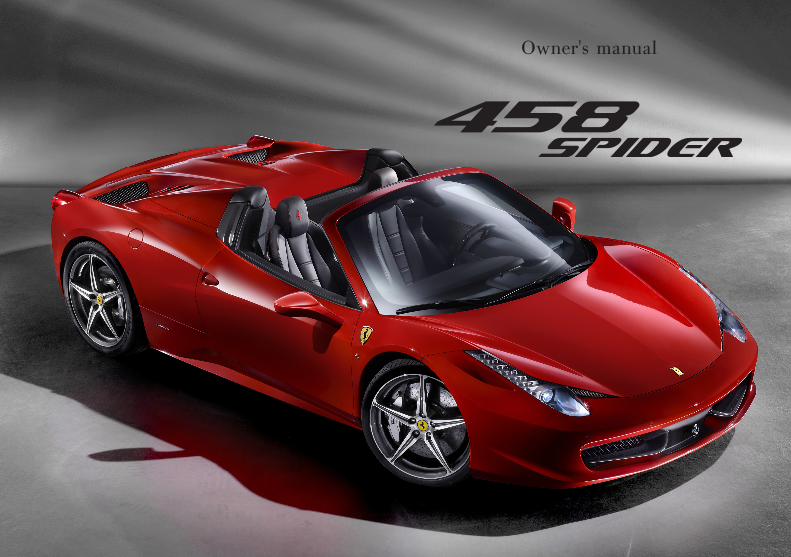
Owner's manual


4 Introduction
General remarks
This vehicle, which complies with EC homologation parameters, uses advanced technology and is capable of achieving high performance levels. It is equipped with sophisticated active and passive safety systems (described below).
These safety features and systems do not authorise the driver to take risks other than those involved in normal driving since their preventive and protective action is guaranteed only in certain conditions. Unless otherwise instructed specifically by Ferrari (see the Safety chapter), the deactivation of any of the vehicle’s safety systems is PROHIBITED.
While certain safety systems (e.g. the airbags) have been tested to ensure that they offer the highest possible levels of protection, they may nonetheless be hazardous in the event of failure by the driver or passenger to observe the instructions given by Ferrari. All vehicle occupants must be attentive at all times and take particular care when transporting passengers who are more subject to injury such as children, disabled and elderly persons.
Safe driving is subject to the following conditions AT ALL TIMES:- the driver must be in perfect psycho-physical condition;- road regulations (Traffic Regulations - Vienna Convention
on Road Traffic that ended on 8 November 1968) must be strictly observed;
- common rules of caution must always be observed in relation to the quality/performance of the vehicle, driving conditions and contingent situations.
- Caution and discipline are the basis of safe driving.- Driving takes place in a naturally dangerous context where a
number of different risk factors interact. For this reason, it is important to drive bearing in mind that others, whether they are pedestrians, motorcyclists or motorists, can make mistakes. Keeping a safe distance allows emergency measures to be taken. Remember that national and international legislation requires that the driver of the vehicle must be capable of performing corrective and/or emergency manoeuvres at all times.
- Correct and careful use of a vehicle derives, above all, from respect for one's own safety and that of others as well as from compliance with road regulations. Only this respect will help you experience all the emotions that driving this car can offer you.
The driver MUST NEVER allow passengers to increase the risks associated with driving (e.g. by not using safety systems such as the seat belts) by failing to observe the mandatory safety rules that apply to both driver and passengers.
The vehicle MUST NOT be modified or tampered with for any reason whatsoever since, by so doing, the manufacturer's homologation and safety parameters will be modified.
5Introduction
The driver must pay the utmost attention to the signals of the vehicle and, in particular, the warning lights on the dashboard and buzzers. Even when the warning lights do not indicate a situation of immediate danger, the driver must be cautious in relation to possible consequences/degeneration of the failure and other information given.During routine operations, such as refuelling, precautions should always been taken and it is important to check that flammable liquid has not been spilled; these precautions must be observed even if the operation is performed by others. Similarly, before setting off make sure that the doors are closed by checking the warning lights and also manually.The driver must be fully acquainted with the vehicle and its controls in order to handle and drive it correctly. Command of the vehicle can be acquired/improved by attending the driving courses held by Ferrari which we strongly recommend. The use of terms from the motor sports world (such as F1, SPORT and RACE) is merely indicative of the vehicle's competition-derived technology and does not endorse inappropriate behaviour on the road which does not comply with Traffic Regulations.
Most accidents are caused by distraction. The driver must use any on-board information, communication and entertainment systems responsibly, especially when the vehicle is in motion. Examples of information, communication and entertainment systems are the following: satellite navigation systems, traffic information systems (e.g. ITT), media players (e.g. iPod), telephones with Bluetooth connectivity, etc. (whether merely audio-based or with display).
It is important to bear in mind that on-board systems may be distracting when driving since they may take a driver's attention away from the road for several seconds.Aftermarket video entertainment systems for the passenger (e.g. TV) must be installed where they cannot distract the driver while the vehicle is in motion. While the vehicle is in motion, the attention required to use on-board systems must never exceed the high level of attention required to drive safely in accordance with the Traffic Regulations. Therefore, these systems may only be used (separately or in combination with others) by the driver:- in complete safety (stopping the vehicle before use if
necessary). Operations that are not involved with driving (e.g. changing dashboard functions), must be performed in maximum safety when the vehicle is stationary;
6 Introduction
- putting road safety first; for example, under conditions of poor or limited visibility, looking at a display with active programmes can be distracting even if you take your eye off the road only for a split second;
- ensuring, if the previous vehicle owner has installed systems on the vehicle that are NOT APPROVED by Ferrari (car tuning), that they are fully compatible with the original vehicle equipment.
If the vehicle owner has installed one or more new systems, either fixed or removable, on the vehicle, make sure that these- have the necessary certification;- are fully compatible with the original vehicle equipment (i.e.
they do not interfere with it);- are fitted by skilled staff.
The Ferrari Technical Service Department and Ferrari Dealers and Authorised Service Centres can provide all the information needed to ensure that they are compatible.
Strict priority criteria must be observed when driving a vehicle: you must not therefore take your attention and eye off the road.In some countries, the use of entertainment/information systems is prohibited on vehicles when driving.The driver is responsible for use of these entertainment/information systems with video screens if they are prohibited in the country where the vehicle will be driven.These considerations are not exhaustive, but only refer to a number of general issues that will be specifically dealt with in this Owner's Manual.
7Introduction
IntroductionThe aim of this Owner’s Manual is to help you get the best value from your vehicle and to provide information on routine maintenance: we advise you to read it carefully before setting out. The Owner’s Manual should be considered an integral part of the vehicle and must therefore always be kept on board.Using the vehicle in a way that does NOT comply with the Owner's Manual not only exonerates Ferrari of any responsibility but also puts the person at great risk.
UpdatingThe high quality level of the vehicle is subject to constant technological improvements. Therefore, there may be differences between this manual and your vehicle.The Ferrari Sales and Service Network will provide you with all the information on any updates.All specifications and illustrations contained in this manual are accurate as of the date of printing.
Spare partsWhen replacing parts or topping up with lubricants and fluids, we recommend that you use original spare parts and lubricants and fluids recommended by Ferrari.
Warranty BookletEach new vehicle comes equipped with a “Warranty Booklet”.This contains the vehicle’s warranty validity conditions.This warranty does not affect the buyer's statutory rights as a consumer, which derive from binding legal norms in his or her favour, in the various states or countries or from European Union regulations, towards the Dealer.The Warranty Booklet also contains the routine maintenance indicated in the “Maintenance Schedule”.
8 Introduction
ServiceThe information in this manual is necessary for the use and proper care of the vehicle. In addition, Customers will get maximum satisfaction and results from the vehicle if they carefully follow the instructions contained in it.We recommend that you have all the checks and services performed at Ferrari Authorised Workshops since they have highly skilled staff and the necessary equipment.Please refer to the “Sales and Service Organisation” manual for information on the location of the Ferrari Dealers and Authorised Service Centres.The Ferrari Technical Service Department is at your complete disposal for any information and advice. If you have any doubts about the information provided in this manual or how to use or operate the vehicle, please contact the Ferrari Service Network.
Consulting the manualTo facilitate reading the manual, the topics have been divided into sections and chapters.
1. General
Provides general information about your vehicle.
2. Quick reference guide
Contains all the information you need when using the vehicle for the first time.
3. Safety
Describes the main safety systems in the vehicle.
4. About your vehicle
Provides all necessary information for use of the vehicle.
5. Advice for Emergency Situations
Provides useful advice for solving problems that may occur.
6. Care of the vehicle
Provides advice for cleaning, care and routine maintenance of your vehicle.
7. Glossary
Explains the main technical concepts.
8. Table of Contents
Allows you to quickly identify and locate the information required.
9Introduction
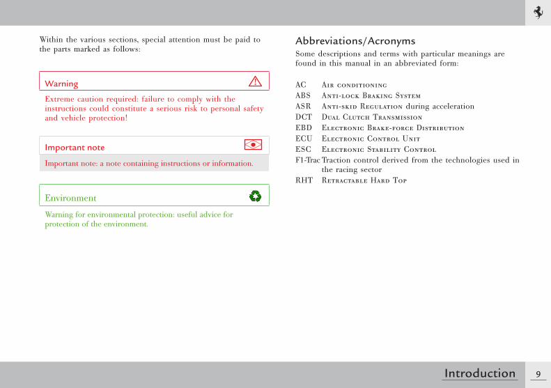
Within the various sections, special attention must be paid to the parts marked as follows:
Warning
Extreme caution required: failure to comply with the instructions could constitute a serious risk to personal safety and vehicle protection!
Important note
Important note: a note containing instructions or information.
Environment
Warning for environmental protection: useful advice for protection of the environment.
Abbreviations/AcronymsSome descriptions and terms with particular meanings are found in this manual in an abbreviated form:
AC Air conditioningABS Anti-lock Braking SystemASR Anti-skid Regulation during accelerationDCT Dual Clutch TransmissionEBD Electronic Brake-force DistributionECU Electronic Control UnitESC Electronic Stability ControlF1-Trac Traction control derived from the technologies used in
the racing sectorRHT Retractable Hard Top
10 Introduction
Environmental protection
Environment
The following chapter contains useful advice for environmental protection.
Ferrari has designed and constructed a vehicle using technologies, materials and devices capable of reducing the harmful impact on the environment to a minimum.If you use your vehicle with respect for the environment, you too will contribute towards environmental protection.Fuel consumption as well as engine, gearbox, brakes and tyres wear mainly depend on two factors:- use of the vehicle;- driving style.Both factors are influenced by the driver.
Use of the vehicle
- Avoid using the vehicle for short trips.- Check that the tyre pressure is correct.- Check the fuel consumption.- Proper periodic maintenance will contribute to preserving your
vehicle in full working order and to protecting the environment. We therefore advise you to respect the service due dates indicated in the “Maintenance Schedule”.
Driving style
- Do not accelerate during the starting procedure.- Do not warm up the engine when the vehicle is stationary.- Drive carefully and keep a safety distance that corresponds to the
driving speed.- Avoid sudden and frequent acceleration or braking.- Turn off the engine if the vehicle is kept stationary for long
periods of time.- Shift gears using only 2/3 of the speed permitted for each gear.- Use the air conditioning in moderation.- A driving style like that described above protects the vehicle
from premature wear and tear, makes driving safer and does not subject the vehicle to undue fatigue.
Important note
The vehicle is equipped with exhaust gas control and monitoring systems which must always be kept in perfect working order and controlled regularly.
11Introduction
Directive for the treatment of end-of-life vehicles (EU only)For many years, Ferrari has been globally committed to respecting and protecting the environment by constantly improving its manufacturing processes and developing increasingly eco-compatible products.Regulations for the treatment of end-of-life vehicles, implemented in response to the terms of EU Directive 2000/53, require that producers (manufacturers and official importers) collect all the vehicles introduced on the market by the producers themselves at the end of their life cycle, and ensure that these vehicles are processed in an environmentally compatible manner.To hand over your Ferrari at the end of its life cycle for treatment at no additional cost (excluding deregistration and transport), take your vehicle to the nearest Ferrari dealer, which will, at its own expense, transport the vehicle to one of the authorised collection and demolition centres, which have been selected to ensure that all processes for the collection, treatment and recovery of recyclable materials are carried out in an environmentally compatible manner.For further information, visit the website www.ferrari.com.When handing over a Ferrari vehicle at the end of its life cycle:- the vehicle must be complete, containing all the essential
elements such as the engine, transmission, bodywork, ECUs and catalytic converters;
- the vehicle must not contain any additional refuse.Ferrari is committed to offering its clients a geographically extensive and, as a result, better service, and thanks you for your cooperation in this environmental challenge.
Bear in mind that specific regulations govern the disposal of vehicle parts including batteries, tyres, used oil, etc.Please contact the Ferrari Service Network for more information.
Vehicle keys ...........................................................14Alarm system .........................................................15Duplicating the keys ..............................................16Replacing remote control batteries .........................17Electronic alarm ....................................................17Identification and homologation plates and labels ..20Dimensions and weights ........................................26Main engine specifications .....................................27Consumption and emissions ..................................27Performance ..........................................................27Wheel rims and tyres .............................................28Refilling .................................................................31
GENERAL
1
14 General
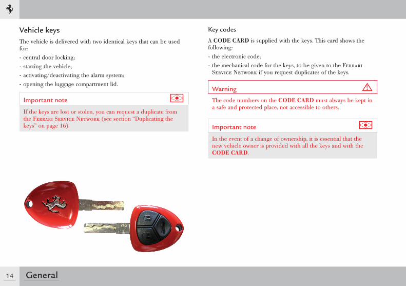
Vehicle keysThe vehicle is delivered with two identical keys that can be used for:- central door locking;- starting the vehicle;- activating/deactivating the alarm system;- opening the luggage compartment lid.
Important note
If the keys are lost or stolen, you can request a duplicate from the Ferrari Service Network (see section “Duplicating the keys” on page 16).
Key codes
A CODE CARD is supplied with the keys. This card shows the following:- the electronic code;- the mechanical code for the keys, to be given to the Ferrari
Service Network if you request duplicates of the keys.
Warning
The code numbers on the CODE CARD must always be kept in a safe and protected place, not accessible to others.
Important note
In the event of a change of ownership, it is essential that the new vehicle owner is provided with all the keys and with the CODE CARD.
15General
1 Alarm system
The FERRARI CODE system
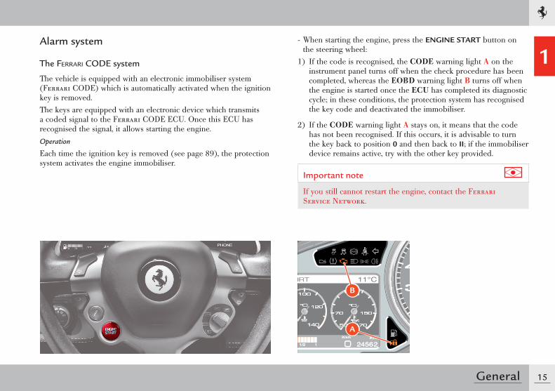
The vehicle is equipped with an electronic immobiliser system (Ferrari CODE) which is automatically activated when the ignition key is removed.The keys are equipped with an electronic device which transmits a coded signal to the Ferrari CODE ECU. Once this ECU has recognised the signal, it allows starting the engine.Operation
Each time the ignition key is removed (see page 89), the protection system activates the engine immobiliser.
- When starting the engine, press the ENGINE START button on the steering wheel:
1) If the code is recognised, the CODE warning light A on the instrument panel turns off when the check procedure has been completed, whereas the EOBD warning light B turns off when the engine is started once the ECU has completed its diagnostic cycle; in these conditions, the protection system has recognised the key code and deactivated the immobiliser.
2) If the CODE warning light A stays on, it means that the code has not been recognised. If this occurs, it is advisable to turn the key back to position 0 and then back to II; if the immobiliser device remains active, try with the other key provided.
Important note
If you still cannot restart the engine, contact the Ferrari Service Network.
B
A
16 General
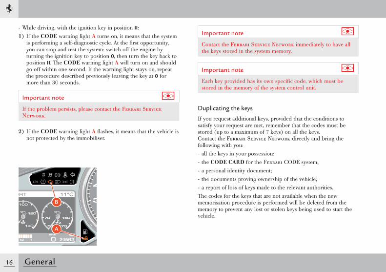
- While driving, with the ignition key in position II:1) If the CODE warning light A turns on, it means that the system
is performing a self-diagnostic cycle. At the fi rst opportunity, you can stop and test the system: switch off the engine by turning the ignition key to position 0, then turn the key back to position II. The CODE warning light A will turn on and should go off within one second. If the warning light stays on, repeat the procedure described previously leaving the key at 0 for more than 30 seconds.
Important note
If the problem persists, please contact the Ferrari Service Network.
2) If the CODE warning light A fl ashes, it means that the vehicle is not protected by the immobiliser.
Important note
Contact the Ferrari Service Network immediately to have all the keys stored in the system memory.
Important note
Each key provided has its own specifi c code, which must be stored in the memory of the system control unit.
Duplicating the keys
If you request additional keys, provided that the conditions to satisfy your request are met, remember that the codes must be stored (up to a maximum of 7 keys) on all the keys. Contact the Ferrari Service Network directly and bring the following with you:- all the keys in your possession;- the CODE CARD for the Ferrari CODE system;- a personal identity document;- the documents proving ownership of the vehicle;- a report of loss of keys made to the relevant authorities.The codes for the keys that are not available when the new memorisation procedure is performed will be deleted from the memory to prevent any lost or stolen keys being used to start the vehicle.
B
A
17General
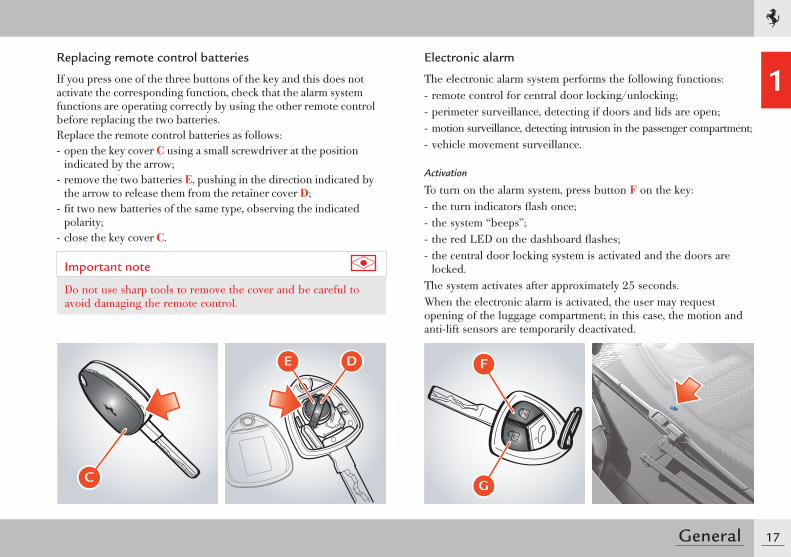
1Replacing remote control batteries
If you press one of the three buttons of the key and this does not activate the corresponding function, check that the alarm system functions are operating correctly by using the other remote control before replacing the two batteries.Replace the remote control batteries as follows:- open the key cover C using a small screwdriver at the position
indicated by the arrow;- remove the two batteries E, pushing in the direction indicated by
the arrow to release them from the retainer cover D;- fit two new batteries of the same type, observing the indicated
polarity;- close the key cover C.
Important note
Do not use sharp tools to remove the cover and be careful to avoid damaging the remote control.
Electronic alarm
The electronic alarm system performs the following functions:- remote control for central door locking/unlocking;- perimeter surveillance, detecting if doors and lids are open;- motion surveillance, detecting intrusion in the passenger compartment;- vehicle movement surveillance.
Activation
To turn on the alarm system, press button F on the key:- the turn indicators flash once;- the system “beeps”;- the red LED on the dashboard flashes;- the central door locking system is activated and the doors are
locked.The system activates after approximately 25 seconds.When the electronic alarm is activated, the user may request opening of the luggage compartment; in this case, the motion and anti-lift sensors are temporarily deactivated.
C
� �
G
F
18 General
If the luggage compartment is then closed, the sensors will be reactivated.If the turn indicators and the red LED on the dashboard flash 9 times when you activate the alarm system, it means that one of the doors or the front/rear lid is open or not closed properly and is therefore not protected by the perimeter surveillance. If this is the case, check that the doors and front/rear lids are closed properly and close any door or lid that is open without deactivating the alarm system: the turn indicators will flash once to indicate that the door or the front/rear lid is now closed properly and is protected by the perimeter surveillance.
Warning
If the turn indicators and the red LEDs on the dashboard flash 9 times when the alarm system is activated with doors, rear and front lids properly closed, it means that the self-diagnostic feature has detected a malfunction in the system. Contact the Ferrari Service Network to have the system checked.
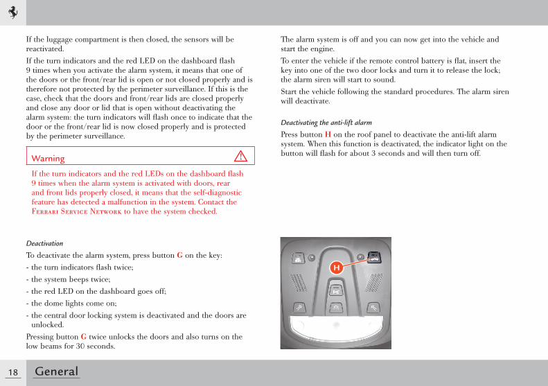
Deactivation
To deactivate the alarm system, press button G on the key:- the turn indicators flash twice;- the system beeps twice;- the red LED on the dashboard goes off;- the dome lights come on;- the central door locking system is deactivated and the doors are
unlocked.Pressing button G twice unlocks the doors and also turns on the low beams for 30 seconds.
The alarm system is off and you can now get into the vehicle and start the engine.To enter the vehicle if the remote control battery is flat, insert the key into one of the two door locks and turn it to release the lock; the alarm siren will start to sound. Start the vehicle following the standard procedures. The alarm siren will deactivate.
Deactivating the anti-lift alarm
Press button H on the roof panel to deactivate the anti-lift alarm system. When this function is deactivated, the indicator light on the button will flash for about 3 seconds and will then turn off.
H
19General
1Alarm memory
If the CODE symbol (see page 116) appears on the left TFT display for 10 seconds when the vehicle is started after system diagnosis together with the message “Break-in attempted”, this means that an intrusion has been attempted and has activated the alarm.In this case, the system will indicate the reason for the alarm activation according to the following priority:- LED off twice: lifting sensor alarm- LED off three times: door alarm- LED off four times: luggage compartment lid alarm- LED off five times: ignition key alarm.The alarm system memory is reset by turning the ignition key.
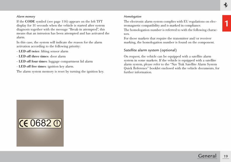
Homologation
The electronic alarm system complies with EU regulations on elec-tromagnetic compatibility and is marked in compliance.The homologation number is referred to with the following charac-ters.For those markets that require the transmitter and/or receiver marking, the homologation number is found on the component.
Satellite alarm system (optional)
On request, the vehicle can be equipped with a satellite alarm system in some markets. If the vehicle is equipped with a satellite alarm system, please refer to the “Nav Trak Satellite Alarm System Quick Reference” booklet enclosed with the vehicle documents, for further information.
20 General
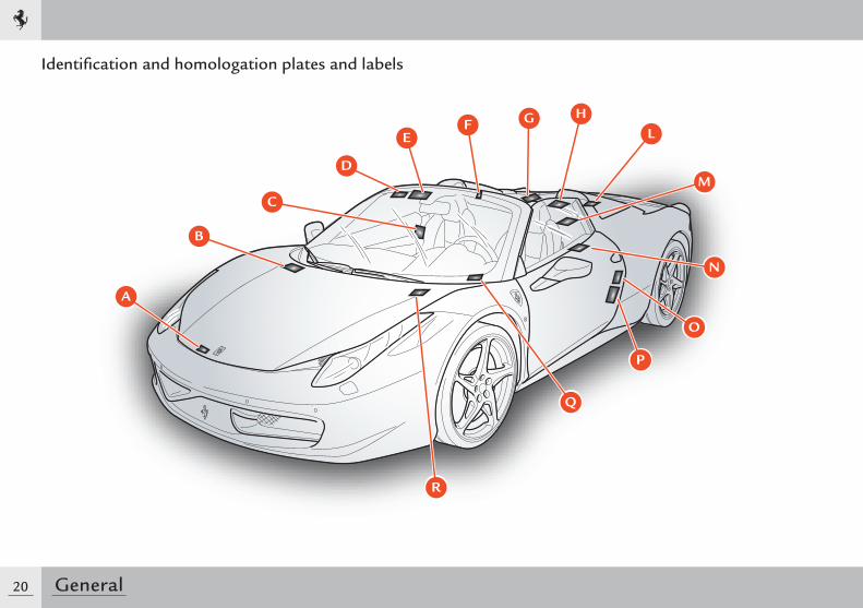
Identifi cation and homologation plates and labels
A
B
D
EF G
L
M
O
P
N
H
C
Q
R
21General
1
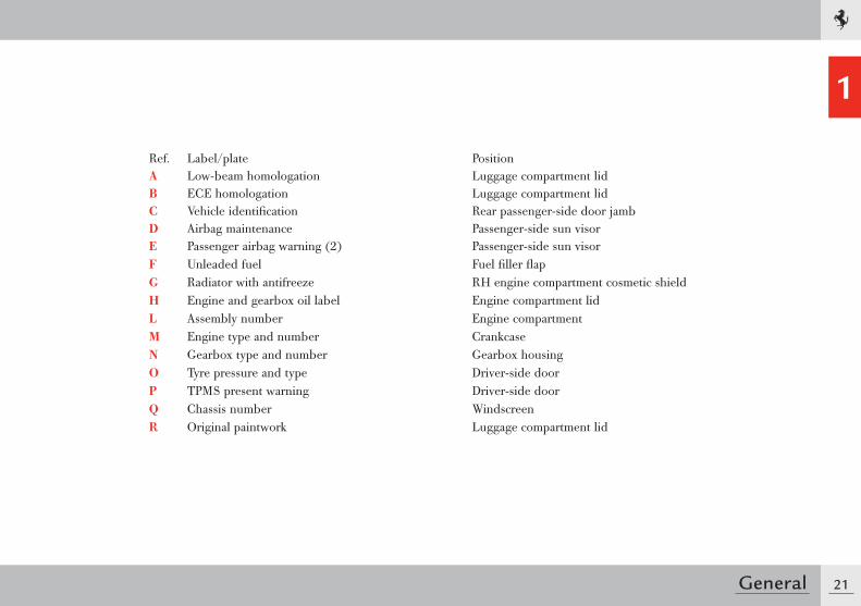
Ref. Label/plate PositionA Low-beam homologation Luggage compartment lidB ECE homologation Luggage compartment lidC Vehicle identification Rear passenger-side door jambD Airbag maintenance Passenger-side sun visorE Passenger airbag warning (2) Passenger-side sun visorF Unleaded fuel Fuel filler flapG Radiator with antifreeze RH engine compartment cosmetic shieldH Engine and gearbox oil label Engine compartment lidL Assembly number Engine compartmentM Engine type and number CrankcaseN Gearbox type and number Gearbox housingO Tyre pressure and type Driver-side doorP TPMS present warning Driver-side doorQ Chassis number WindscreenR Original paintwork Luggage compartment lid
22 General
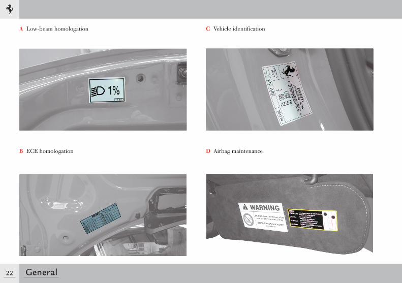
A Low-beam homologation
B ECE homologation
C Vehicle identification
D Airbag maintenance
23General
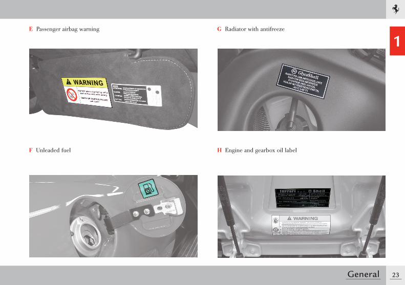
1E Passenger airbag warning
F Unleaded fuel
G Radiator with antifreeze
H Engine and gearbox oil label
24 General
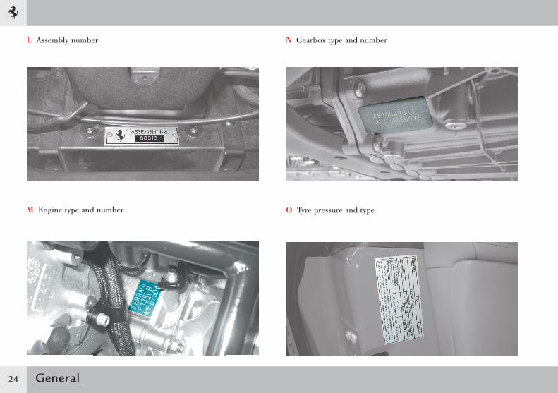
L Assembly number
M Engine type and number
N Gearbox type and number
O Tyre pressure and type
25General
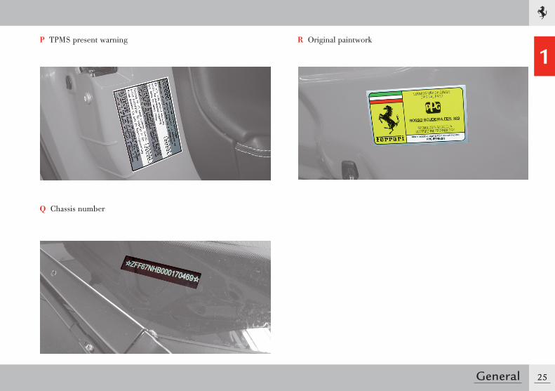
1P TPMS present warning
Q Chassis number
R Original paintwork
26 General
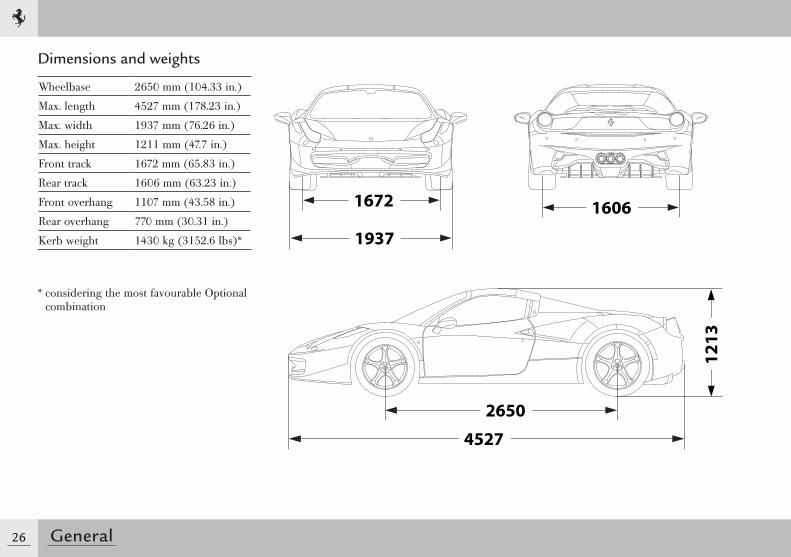
Dimensions and weights
Wheelbase 2650 mm (104.33 in.)
Max. length 4527 mm (178.23 in.)
Max. width 1937 mm (76.26 in.)
Max. height 1211 mm (47.7 in.)
Front track 1672 mm (65.83 in.)
Rear track 1606 mm (63.23 in.)
Front overhang 1107 mm (43.58 in.)
Rear overhang 770 mm (30.31 in.)
Kerb weight 1430 kg (3152.6 lbs)*
* considering the most favourable Optional combination
1672
1937
2650
4527
1606
12
13
27General
1Main engine specifications
Type F 136 FB
Number of cylinders 8
Cylinder sequence V 90°
Cylinder bore 94 mm (3.7 in.)
Piston stroke 81 mm (3.2 in.)
Total displacement 4497 cm3 (274.4 cu. in.)
Compression ratio 12.5:1
Maximum RPM (with limiting device)
9200 RPM
Max. power 416 kW (565 HP)
Corresponding RPM 9000 RPM
Max. torque 540 Nm
Corresponding RPM 6000 RPM
Consumption and CO2 emissions
Standard version HELE version
l/100 km g/km l/100 km g/km
City cycle 19.7 454 15.8 369
Motorway 9.7 223 9.4 221
Combined cycle 13.3 307 11.8 275
Transmission ratios
Gearbox ratios Differential/bevel gear pair ratio
1 = 3.077
2 = 2.185
3 = 1.626 5.143
4 = 1.286
5 = 1.028
6 = 0.839
7 = 0.693
R = 2.791
Performance
0 - 100 km/h 0 - 400 m Max. speed
< 3.5 s 11.3 s > 320 km/h (198.8 mph)
Electrical system
Supply voltage Alternator
12 V Nippondenso 165 A SC3
Battery Starter motor
Fiamm 12V - 70 A/h L3 VRLA 760A EN
Bosch
28 General
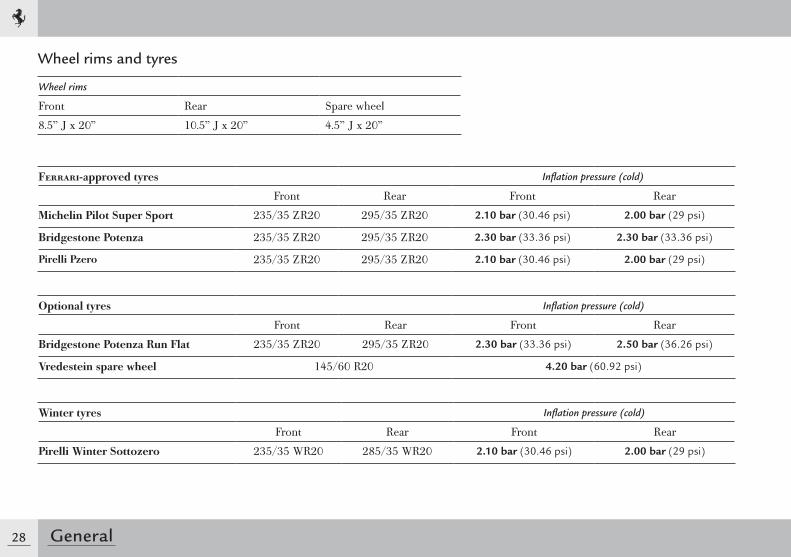
Wheel rims and tyres
Wheel rims
Front Rear Spare wheel
8.5” J x 20” 10.5” J x 20” 4.5” J x 20”
Ferrari-approved tyres Inflation pressure (cold)
Front Rear Front Rear
Michelin Pilot Super Sport 235/35 ZR20 295/35 ZR20 2.10 bar (30.46 psi) 2.00 bar (29 psi)
Bridgestone Potenza 235/35 ZR20 295/35 ZR20 2.30 bar (33.36 psi) 2.30 bar (33.36 psi)
Pirelli Pzero 235/35 ZR20 295/35 ZR20 2.10 bar (30.46 psi) 2.00 bar (29 psi)
Optional tyres Inflation pressure (cold)
Front Rear Front Rear
Bridgestone Potenza Run Flat 235/35 ZR20 295/35 ZR20 2.30 bar (33.36 psi) 2.50 bar (36.26 psi)
Vredestein spare wheel 145/60 R20 4.20 bar (60.92 psi)
Winter tyres Inflation pressure (cold)
Front Rear Front Rear
Pirelli Winter Sottozero 235/35 WR20 285/35 WR20 2.10 bar (30.46 psi) 2.00 bar (29 psi)
29General
1Correct reading of tyre manufactured in the EU
Example: 235/35 ZR20235 = Nominal width (distance in mm from side to side)35 = Height/width ratio as a percentageZ = Tyre to be used for speeds of over 240 km/h (149 mph)R = Radial tyre20 = Rim diameter in inches
W = Tyre that supports a maximum speed of 270 km/h
The tyre manufacture date is included in the description of the tyre:DOT ... 1009 means that the tyre was manufactured in the 10th week of 2009.
Correct rim reading
Example: 8.5” J x 20”8.5 = Rim width in inchesJ = Shape of rim flange
(side projection where tyre bead rests)20 = Rim diameter in inches
(corresponds to the diameter of tyre to be fitted)
For further information on tyres, see page 235.
30 General
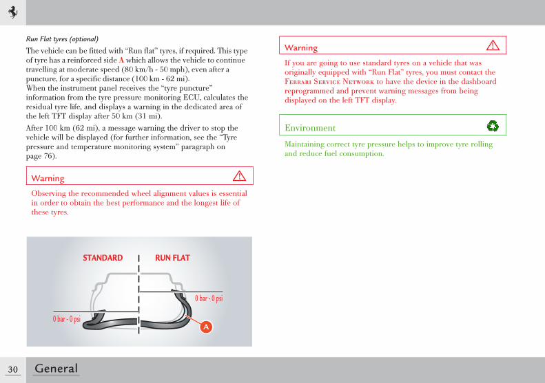
Run Flat tyres (optional)
The vehicle can be fitted with “Run flat” tyres, if required. This type of tyre has a reinforced side A which allows the vehicle to continue travelling at moderate speed (80 km/h - 50 mph), even after a puncture, for a specific distance (100 km - 62 mi).When the instrument panel receives the “tyre puncture” information from the tyre pressure monitoring ECU, calculates the residual tyre life, and displays a warning in the dedicated area of the left TFT display after 50 km (31 mi). After 100 km (62 mi), a message warning the driver to stop the vehicle will be displayed (for further information, see the “Tyre pressure and temperature monitoring system” paragraph on page 76).
Warning
Observing the recommended wheel alignment values is essential in order to obtain the best performance and the longest life of these tyres.
Warning
If you are going to use standard tyres on a vehicle that was originally equipped with “Run Flat” tyres, you must contact the Ferrari Service Network to have the device in the dashboard reprogrammed and prevent warning messages from being displayed on the left TFT display.
Environment
Maintaining correct tyre pressure helps to improve tyre rolling and reduce fuel consumption.
�
31General
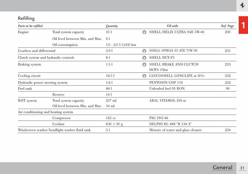
1RefillingParts to be refilled Quantity Fill with: Ref. Page
Engine Total system capacity 10 l SHELL HELIX ULTRA SAE 5W-40 230
Oil level between Min. and Max. 2 l
Oil consumption 1.0 - 2.0 l/1,000 km
Gearbox and differential 3.9 l SHELL SPIRAX S5 ATE 75W-90 231
Clutch system and hydraulic controls 8 l SHELL DCT-F3
Braking system 1.5 l SHELL BRAKE AND CLUTCHDOT4 Ultra
233
Cooling circuit 16.5 l GLYCOSHELL LONGLIFE at 50% 232
Hydraulic power steering system 1.6 l PENTOSIN CHF 11S 232
Fuel tank 86 l Unleaded fuel 95 RON. 90
Reserve 14 l
RHT system Total system capacityOil level between Min. and Max.
257 ml34 ml
ARAL VITAMOL ZH-m
Air conditioning and heating system
Compressor 165 cc PAG ISO 46
Coolant 630 ± 30 g DELPHI RL 488 “R 134 A”
Windscreen washer/headlight washer fluid tank 5 l Mixture of water and glass cleaner 234
32 General
Important note
This vehicle is suitable for use with unleaded fuel with a maximum of 10% ethanol (E10).
Warning
The use of fuel with 10% - 25% ethanol can cause malfunctioning.The use of fuel with over 25% ethanol can cause permanent damage to the engine fuel system parts.

Opening doors ......................................................36Controls overview ..................................................37Seat adjustment ....................................................39Steering wheel adjustment .....................................40Rear-view mirrors ..................................................41Seat belts ..............................................................42Ignition switch .......................................................43External lights and turn indicators ..........................44Starting and driving the vehicle ...............................46
QUICK REFERENCE GUIDE
2
36 Quick reference guide
Opening
Doors
When a door is opened or closed, the window automatically moves down by approximately 2 centimetres / 0.8 inches (to its “target position”) to avoid colliding with the upper weather strip.When the door is closed, the window automatically moves up until it reaches the “upper limit”.
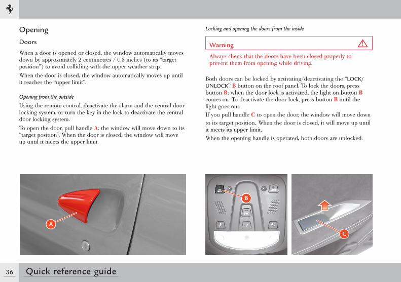
Opening from the outside
Using the remote control, deactivate the alarm and the central door locking system, or turn the key in the lock to deactivate the central door locking system.To open the door, pull handle A: the window will move down to its “target position”. When the door is closed, the window will move up until it meets the upper limit.
Locking and opening the doors from the inside
Warning
Always check that the doors have been closed properly to prevent them from opening while driving.
Both doors can be locked by activating/deactivating the “LOCK/UNLOCK” B button on the roof panel. To lock the doors, press button B; when the door lock is activated, the light on button B comes on. To deactivate the door lock, press button B until the light goes out.If you pull handle C to open the door, the window will move down to its target position. When the door is closed, it will move up until it meets its upper limit.When the opening handle is operated, both doors are unlocked.
B
�
C
37
2
Quick reference guide
456
23
111
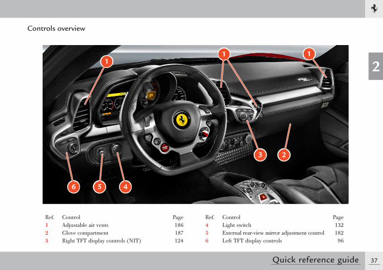
Controls overview
Ref. Control Page1 Adjustable air vents 1862 Glove compartment 1873 Right TFT display controls (NIT) 124
Ref. Control Page4 Light switch 1325 External rear-view mirror adjustment control 1826 Left TFT display controls 96
38 Quick reference guide
10
15
14
13
10
11
12
987
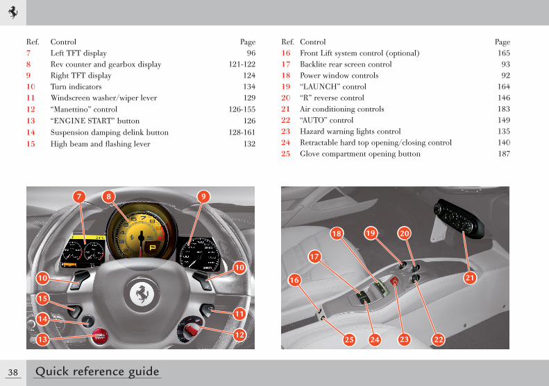
Ref. Control Page7 Left TFT display 968 Rev counter and gearbox display 121-122 9 Right TFT display 12410 Turn indicators 13411 Windscreen washer/wiper lever 12912 “Manettino” control 126-15513 “ENGINE START” button 12614 Suspension damping delink button 128-16115 High beam and flashing lever 132
21
22232425
16
17
18 19 20
Ref. Control Page16 Front Lift system control (optional) 16517 Backlite rear screen control 9318 Power window controls 9219 “LAUNCH” control 16420 “R” reverse control 14621 Air conditioning controls 18322 “AUTO” control 14923 Hazard warning lights control 13524 Retractable hard top opening/closing control 14025 Glove compartment opening button 187
39
2
Quick reference guide
Adjustments
Seats
Warning
As with all adjustment, seat adjustment must be performed when the vehicle is stationary.
Correct adjustment is very important for enhanced driving comfort and maximum efficiency of the passive safety systems.
Basic seat
The seat position can be adjusted using the special controls.
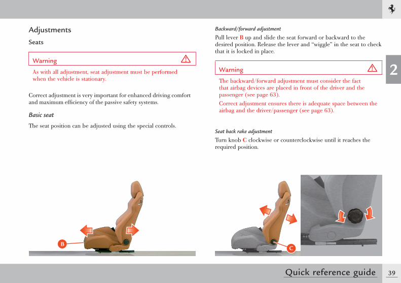
Backward/forward adjustment
Pull lever B up and slide the seat forward or backward to the desired position. Release the lever and “wiggle” in the seat to check that it is locked in place.
Warning
The backward/forward adjustment must consider the fact that airbag devices are placed in front of the driver and the passenger (see page 63).Correct adjustment ensures there is adequate space between the airbag and the driver/passenger (see page 63).
Seat back rake adjustment
Turn knob C clockwise or counterclockwise until it reaches the required position.
BC
40 Quick reference guide
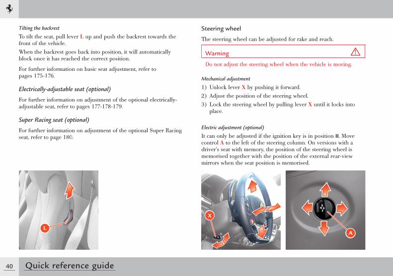
Tilting the backrest
To tilt the seat, pull lever L up and push the backrest towards the front of the vehicle.When the backrest goes back into position, it will automatically block once it has reached the correct position.
For further information on basic seat adjustment, refer to pages 175-176.
Electrically-adjustable seat (optional)
For further information on adjustment of the optional electrically-adjustable seat, refer to pages 177-178-179.
Super Racing seat (optional)
For further information on adjustment of the optional Super Racing seat, refer to page 180.
Steering wheel
The steering wheel can be adjusted for rake and reach.
Warning
Do not adjust the steering wheel when the vehicle is moving.
Mechanical adjustment
1) Unlock lever X by pushing it forward.2) Adjust the position of the steering wheel.3) Lock the steering wheel by pulling lever X until it locks into
place.
Electric adjustment (optional)
It can only be adjusted if the ignition key is in position II. Move control A to the left of the steering column. On versions with a driver's seat with memory, the position of the steering wheel is memorised together with the position of the external rear-view mirrors when the seat position is memorised.
L
X
A
41
2
Quick reference guide
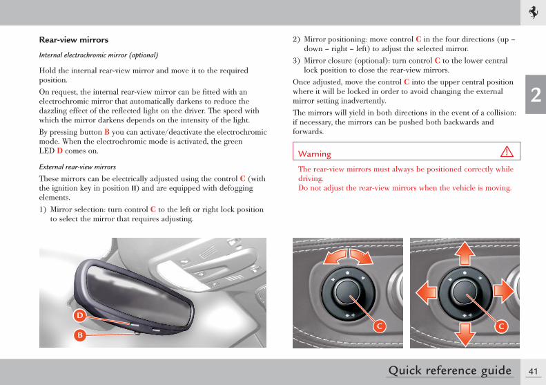
Rear-view mirrors
Internal electrochromic mirror (optional)
Hold the internal rear-view mirror and move it to the required position.On request, the internal rear-view mirror can be fitted with an electrochromic mirror that automatically darkens to reduce the dazzling effect of the reflected light on the driver. The speed with which the mirror darkens depends on the intensity of the light.By pressing button B you can activate/deactivate the electrochromic mode. When the electrochromic mode is activated, the green LED D comes on.
External rear-view mirrors
These mirrors can be electrically adjusted using the control C (with the ignition key in position II) and are equipped with defogging elements.1) Mirror selection: turn control C to the left or right lock position
to select the mirror that requires adjusting.
2) Mirror positioning: move control C in the four directions (up – down – right – left) to adjust the selected mirror.
3) Mirror closure (optional): turn control C to the lower central lock position to close the rear-view mirrors.
Once adjusted, move the control C into the upper central position where it will be locked in order to avoid changing the external mirror setting inadvertently.The mirrors will yield in both directions in the event of a collision: if necessary, the mirrors can be pushed both backwards and forwards.
Warning
The rear-view mirrors must always be positioned correctly while driving. Do not adjust the rear-view mirrors when the vehicle is moving.
C CB
D
42 Quick reference guide
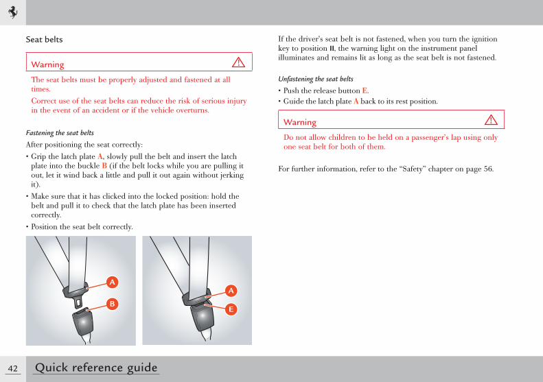
Seat belts
Warning
The seat belts must be properly adjusted and fastened at all times.Correct use of the seat belts can reduce the risk of serious injury in the event of an accident or if the vehicle overturns.
Fastening the seat belts
After positioning the seat correctly:• Grip the latch plate A, slowly pull the belt and insert the latch
plate into the buckle B (if the belt locks while you are pulling it out, let it wind back a little and pull it out again without jerking it).
• Make sure that it has clicked into the locked position: hold the belt and pull it to check that the latch plate has been inserted correctly.
• Position the seat belt correctly.
If the driver’s seat belt is not fastened, when you turn the ignition key to position II, the warning light on the instrument panel illuminates and remains lit as long as the seat belt is not fastened.
Unfastening the seat belts
• Push the release button E.• Guide the latch plate A back to its rest position.
Warning
Do not allow children to be held on a passenger’s lap using only one seat belt for both of them.
For further information, refer to the “Safety” chapter on page 56.
�
�
A
E
43
2
Quick reference guide
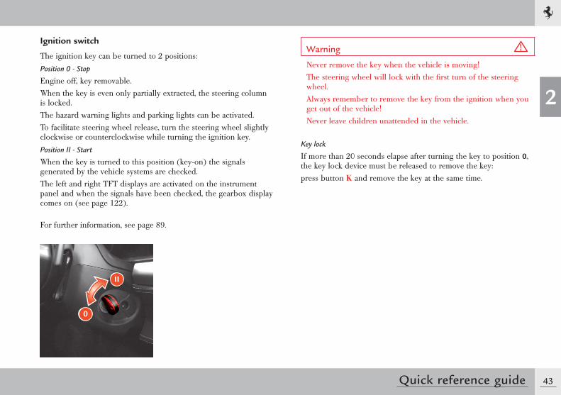
Ignition switch
The ignition key can be turned to 2 positions:Position 0 - Stop
Engine off, key removable.When the key is even only partially extracted, the steering column is locked.The hazard warning lights and parking lights can be activated.To facilitate steering wheel release, turn the steering wheel slightly clockwise or counterclockwise while turning the ignition key.Position II - Start
When the key is turned to this position (key-on) the signals generated by the vehicle systems are checked.The left and right TFT displays are activated on the instrument panel and when the signals have been checked, the gearbox display comes on (see page 122).
For further information, see page 89.
II
0
Warning
Never remove the key when the vehicle is moving!The steering wheel will lock with the first turn of the steering wheel.Always remember to remove the key from the ignition when you get out of the vehicle!Never leave children unattended in the vehicle.
Key lock
If more than 20 seconds elapse after turning the key to position 0, the key lock device must be released to remove the key:press button K and remove the key at the same time.
44 Quick reference guide
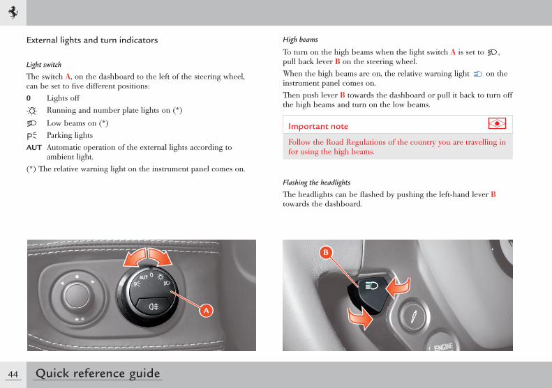
External lights and turn indicators
Light switch
The switch A, on the dashboard to the left of the steering wheel, can be set to five different positions:0 Lights off
Running and number plate lights on (*)
Low beams on (*) Parking lights
AUT Automatic operation of the external lights according to ambient light.
(*) The relative warning light on the instrument panel comes on.
A
High beams
To turn on the high beams when the light switch A is set to , pull back lever B on the steering wheel.When the high beams are on, the relative warning light on the instrument panel comes on.Then push lever B towards the dashboard or pull it back to turn off the high beams and turn on the low beams.
Important note
Follow the Road Regulations of the country you are travelling in for using the high beams.
Flashing the headlights
The headlights can be flashed by pushing the left-hand lever B towards the dashboard.
B
45
2
Quick reference guide
Turn indicators
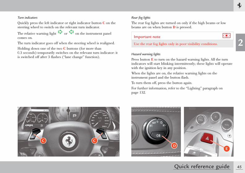
Quickly press the left indicator or right indicator button C on the steering wheel to switch on the relevant turn indicator.
The relative warning light or on the instrument panel comes on.The turn indicator goes off when the steering wheel is realigned.Holding down one of the two C buttons (for more than 0.3 seconds) temporarily switches on the relevant turn indicator: it is switched off after 3 flashes (“lane change” function).
Rear fog lights
The rear fog lights are turned on only if the high beams or low beams are on when button D is pressed.
Important note
Use the rear fog lights only in poor visibility conditions.
Hazard warning lights
Press button E to turn on the hazard warning lights. All the turn indicators will start blinking intermittently; these lights will operate with the ignition key in any position.When the lights are on, the relative warning lights on the instrument panel and the button flash.To turn them off, press the button again.For further information, refer to the “Lighting” paragraph on page 132.
DE
C C
46 Quick reference guide
Starting and driving the vehicle
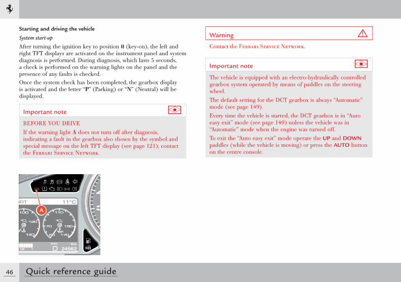
System start-up
After turning the ignition key to position II (key-on), the left and right TFT displays are activated on the instrument panel and system diagnosis is performed. During diagnosis, which lasts 5 seconds, a check is performed on the warning lights on the panel and the presence of any faults is checked.Once the system check has been completed, the gearbox display is activated and the letter “P” (Parking) or “N” (Neutral) will be displayed.
Important note
BEFORE YOU DRIVEIf the warning light A does not turn off after diagnosis, indicating a fault in the gearbox also shown by the symbol and special message on the left TFT display (see page 121), contact the Ferrari Service Network.
Warning
Contact the Ferrari Service Network.
Important note
The vehicle is equipped with an electro-hydraulically controlled gearbox system operated by means of paddles on the steering wheel.The default setting for the DCT gearbox is always “Automatic” mode (see page 149).Every time the vehicle is started, the DCT gearbox is in “Auto easy exit” mode (see page 149) unless the vehicle was in “Automatic” mode when the engine was turned off.To exit the “Auto easy exit” mode operate the UP and DOWN paddles (while the vehicle is moving) or press the AUTO button on the centre console.
A
47
2
Quick reference guide
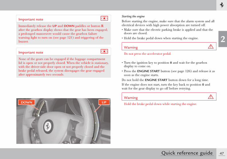
Important note
Immediately release the UP and DOWN paddles or button R after the gearbox display shows that the gear has been engaged; a prolonged manoeuvre would cause the gearbox failure warning light to turn on (see page 121) and triggering of the buzzer.
Important note
None of the gears can be engaged if the luggage compartment lid is open or not properly closed. When the vehicle is stationary, with the driver-side door open or not properly closed and the brake pedal released, the system disengages the gear engaged after approximately two seconds.
Starting the engine
Before starting the engine, make sure that the alarm system and all electrical devices with high power absorption are turned off.• Make sure that the electric parking brake is applied and that the
doors are closed.• Hold the brake pedal down when starting the engine.
Warning
Do not press the accelerator pedal.
• Turn the ignition key to position II and wait for the gearbox display to come on.
• Press the ENGINE START button (see page 126) and release it as soon as the engine starts.
Do not hold the ENGINE START button down for a long time.If the engine does not start, turn the key back to position 0 and wait for the gear display to go off before retrying.
Warning
Hold the brake pedal down while starting the engine.DOWN UP
48 Quick reference guide
If the engine fails to start after several attempts, check for one of the following causes:• insufficient speed of the starter motor (flat battery)• ignition device faulty• electrical contacts faulty• fuel pump fuses blown.
Warming up the engine
Do not run the engine at high speed until the engine oil temperature has reached at least 65-70 °C (149-158 °F), approximately.
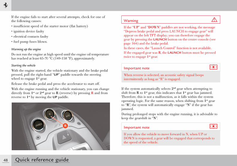
Starting the vehicle
With the engine started, the vehicle stationary and the brake pedal pressed, pull the right-hand “UP” paddle towards the steering wheel to engage 1st gear.Release the brake pedal and press the accelerator to start off.With the engine running and the vehicle stationary, you can change directly from 1st or 2nd gear to R (reverse) by pressing R and from reverse to 1st by moving the UP paddle.
Warning
If the “UP” and “DOWN” paddles are not working, the message “Depress brake pedal and press LAUNCH to engage gear” will appear on the left TFT display; you can therefore engage the gear by pressing the LAUNCH button on the centre console (see page 164) and the brake pedal.In these cases, the “Launch Control” function is not available.If the engaged gear was R, the LAUNCH button must be pressed twice to engage 1st gear.
Important note
When reverse is selected, an acoustic safety signal beeps intermittently as long as “R” is engaged.
If the system automatically selects 2nd gear when attempting to shift from R to 1st gear, this indicates that 1st gear has jammed. Therefore, this is not a malfunction, as it falls within the system operating logic. For the same reason, when shifting from 1st gear to “R”, the system will automatically engage “N” if the gear has jammed.During prolonged stops with the engine running, it is advisable to keep the gearshift in “N”.
Important note
If you allow the vehicle to move forward in N, when UP or DOWN is requested, a gear will be engaged that corresponds to the speed of the vehicle.
R
49
2
Quick reference guide
UP-shifting
Use the right-hand UP paddle without releasing the accelerator pedal.An UP-shift request is not accepted when engagement of the requested gear forces the engine to underrev or if an UP-shift is already in progress because of engine overrevving.For further information, see page 147.
DOWN-shifting
Use the left-hand DOWN paddle without releasing the accelerator pedal.A DOWN-shift request is not accepted if engagement of the requested gear forces the engine beyond a certain RPM, depending on the gear requested, or if a DOWN-shift is already in progress because of engine underrevving.For further information, see page 147.
“N” (Neutral) request
With the engine running, pull both UP and DOWN paddles towards the steering wheel at the same time without pressing the brake pedal to request neutral “N”.If necessary, “N” can be requested at any speed. Subsequently, if an “UP” or “DOWN” shift is requested, the system will engage the gear most suited to the speed of the vehicle.
Stopping the vehicle
When the vehicle stops, the system automatically engages 1st gear unless Neutral has already been requested.When the vehicle is stationary and the engine is running, hold the brake pedal down until ready to move off again.
Switching off the engine
The engine can be switched off with the gearbox either in “N” or with a gear engaged.After turning the ignition key from position II to position 0, the gearbox display will remain on for a few more seconds to display the engaged gear. If the gearbox is in “N” a buzzer will sound. Before switching off, the letter “P” is displayed on the gearbox display to inform the driver that the Park Lock has been activated.
Warning
Never leave the vehicle with the gearbox in “N”. Always make sure that the letter “P” (Parking) appears on the gearbox display.
For further information, see page 163.

Passive safety .........................................................54Active safety ..........................................................55Seat belts ..............................................................56How to fasten seat belts ........................................58Pretensioners .........................................................60Auxiliary Occupant Protection Systems ...................62Driver and passenger airbags ..................................63Side airbags ...........................................................68Fuel inertia switch ..................................................71ABS and EBD ........................................................72Stability and Traction Control ................................73Electric parking brake ............................................75TPMS (optional) ...................................................76
SAFETY
3
52 Safety
Ferrari has designed and built a high performance vehicle.In order to take advantage of the safety systems described below, it is essential to comply with the indicated regulations.
Special recommendations
This vehicle has been built to comply with homologation regulations that also concern safety and environmental protection.These high technological standards must always be accompanied by careful and cautious driving.Particular attention must be paid to:• Overheated components. High temperatures develop in the
engine compartment near the exhaust system. Do not park the vehicle on paper, grass, dry leaves or other flammable materials. They could catch fire if they come into contact with hot parts of the exhaust system. Do not fit other heat shields or remove those fitted on the exhaust system. Do not let flammable substances come into contact with the exhaust system.
• Moving parts of the vehicle such as belts, fans, etc. They must always be adequately protected. Do not remove the guards or operate on the moving parts without taking due precautions.
• Installations under pressure such as braking system, air conditioning system, cooling system and lubrication system may create pressures inside them. Do not perform any operation which may cause gas or liquids to spill out with the risk of injury to persons and damage to things.
Emissions
Warning
• The exhaust gas generated by the running engine may be hazardous, especially when in closed spaces. As well as consuming oxygen, the engine discharges carbon dioxide, carbon oxide and other toxic gases.
• Fuel is highly inflammable and emits vapours which may be noxious if inhaled. Do not use naked flames or create sparks near the open fuel tank or in any other condition where fuel comes into contact with air.
Lubricants
Warning
• The oils used may also be flammable: take the same precautions as those adopted for fuel.
Flammable fluids
Warning
• The fluid in the battery is poisonous and corrosive. Do not let it spill out and come into contact with the skin, eyes or objects. Do not use naked flames or create sparks near the battery.
Fuel inertia switch
• See page 71.
53
3
Safety
Warning
Seat belts must be worn at all times and must be properly fastened and adjusted!Correct use of the seat belts can significantly reduce the risk and severity of injury if an accident occurs or if the vehicle overturns.
Warning
For an effective restraining action, the seat belt must be fastened correctly with the seat backrest in the upright position.The seat belt is fastened correctly when the upper part of the belt crosses the centre of the shoulder (not the neck) and the abdominal section is fitted over the hips (not the abdomen).Make sure that the belt is not twisted and that it passes closely over your body; if not, in the event of a head-on collision, it may move and cause injury to the abdomen.Avoid wearing bulky clothing that may interfere with the proper operation of the seat belts.
Warning
Each seat belt has been designed to protect only one occupant. If more than one person uses the same seat belt, the risk of injury in the event of an accident is increased.Do not sit babies, small children or other persons on your lap.If there is a collision, the weight of an adult may cause the child to be crushed by the seat belt causing severe or even fatal injuries.
54 Safety
Passive safety
The passive safety system has been designed to reduce the risk and severity of injury if an accident occurs.The vehicle is equipped with the following seat belts:- 3-point driver's seat belt with pretensioner and load limiting
device (see page 56)- 3-point passenger seat belt with pretensioner and load limiting
device (see page 56).
Warning
Auxiliary safety systems are not a substitute for seat belts. All occupants must always wear a seat belt. Correct use of the seat belts combined with use of the auxiliary safety systems provides optimal protection to the occupants in various types of collisions.
The vehicle also has the following auxiliary occupant protection system components (see also page 60 “Auxiliary occupant protection systems”):- front driver's airbag (for operating functions see page 63)- front passenger airbag (for operating functions see page 63)- driver's head protection side airbag (head bag) (for operating
functions see page 68)- passenger head protection side airbag (head bag) (for operating
functions see page 68)- seats (see page 175)- deformable body
- occupant protection system ECU- ECU auxiliary sensors- instrument panel warning light (see page 63)- inertia switch.
Warning
The protective action of the airbags is always integrated with the seat belts and the pretensioners. The compulsory use of the seat belt is provided by the national regulations (in Italy, for example, by the Codice della Strada, i.e. Traffic Regulations).
Deformable body
The deformable body absorbs shock and distributes it over the entire structure of the vehicle allowing progressive deceleration.The passenger compartment structure, on the other hand, has been designed to provide maximum resistance without undergoing deformation in order to guarantee a protective survival cell for the occupants.
55
3
Safety
Active safety
The aim of the active safety system is to reduce the risk of accidents and injury severity.The vehicle has been designed to provide a high level of safety for whoever uses it. The following systems are specific active safety components:• braking system• air conditioning and heating system• external lights• buzzer and warning lights (flashing).The braking system includes the mechanical brake system and the electronic stability and traction control system (ABS and EBD): this is designed to prevent the wheels from locking and to provide good handling and stability.In some situations, fast acceleration is important to get out of dangerous situations. However, always use the accelerator with extreme caution. During acceleration of the driving wheels, the anti-skid system may help you in certain dangerous situations.The air conditioning and heating system in the passenger compartment can add to driving comfort and keep you alert so that you can react quickly when necessary.It is very important to be able to see the road clearly and be seen and external lights must be turned on when the conditions so require.
56 Safety
Seat beltsStatistics show that when used correctly, seat belts reduce the risk of injury in various types of crashes including the risk of ejection from the vehicle and impact with the interior of the vehicle.If not unfastened, the seat belts do not provide any type of protection. Before every trip, always make sure that all occupants are wearing their seat belts.
Warning
Seat belts must be worn at all times and must be properly fastened and adjusted!Correct use of the seat belts can reduce the risk of serious injury in the event of an accident or if the vehicle overturns.
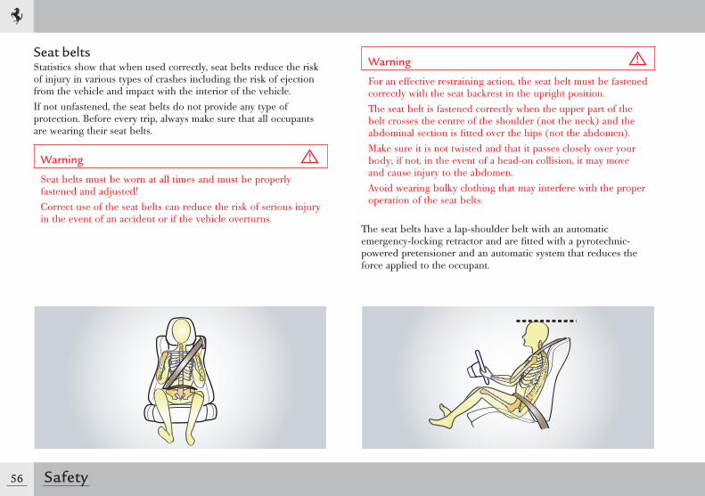
Warning
For an effective restraining action, the seat belt must be fastened correctly with the seat backrest in the upright position.The seat belt is fastened correctly when the upper part of the belt crosses the centre of the shoulder (not the neck) and the abdominal section is fi tted over the hips (not the abdomen).Make sure it is not twisted and that it passes closely over your body; if not, in the event of a head-on collision, it may move and cause injury to the abdomen.Avoid wearing bulky clothing that may interfere with the proper operation of the seat belts.
The seat belts have a lap-shoulder belt with an automatic emergency-locking retractor and are fi tted with a pyrotechnic-powered pretensioner and an automatic system that reduces the force applied to the occupant.
57
3
Safety
Warning
Do not let the seat belts come into contact with cutting edges. They may get damaged and may consequently break in the event of a collision.
Warning
Each seat belt has been designed to protect only one occupant. If more than one person uses the same seat belt, the risk of injury in the event of an accident is increased.The seat belt must never be passed around a baby, child or other person sitting on a passenger's lap.Do not sit babies, small children or other persons on your lap.If there is a collision, the weight of an adult may cause the child to be crushed by the seat belt causing severe or even fatal injuries.
Warning
Do not attach or pin anything onto the seat belts: they may get damaged and may consequently break in the event of a collision.
Warning
If a seat belt has come into contact with cutting edges or was somehow perforated, we recommend that you have it immediately replaced by the Ferrari Service Network.
Warning
Periodically check the condition of the seat belts. If the belt shows signs of wear, it must be checked by a qualified person and replaced if necessary. Contact the Ferrari Service Network immediately.
58 Safety
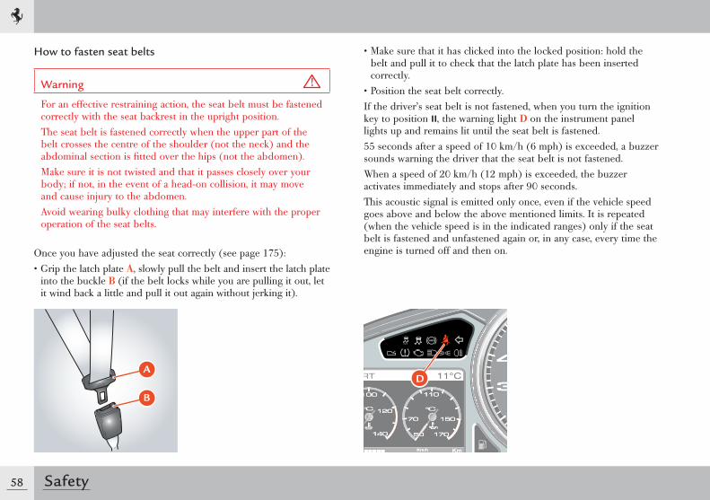
How to fasten seat belts
Warning
For an effective restraining action, the seat belt must be fastened correctly with the seat backrest in the upright position.The seat belt is fastened correctly when the upper part of the belt crosses the centre of the shoulder (not the neck) and the abdominal section is fi tted over the hips (not the abdomen).Make sure it is not twisted and that it passes closely over your body; if not, in the event of a head-on collision, it may move and cause injury to the abdomen.Avoid wearing bulky clothing that may interfere with the proper operation of the seat belts.
Once you have adjusted the seat correctly (see page 175):• Grip the latch plate A, slowly pull the belt and insert the latch plate
into the buckle B (if the belt locks while you are pulling it out, let it wind back a little and pull it out again without jerking it).
• Make sure that it has clicked into the locked position: hold the belt and pull it to check that the latch plate has been inserted correctly.
• Position the seat belt correctly.If the driver’s seat belt is not fastened, when you turn the ignition key to position II, the warning light D on the instrument panel lights up and remains lit until the seat belt is fastened.55 seconds after a speed of 10 km/h (6 mph) is exceeded, a buzzer sounds warning the driver that the seat belt is not fastened.When a speed of 20 km/h (12 mph) is exceeded, the buzzer activates immediately and stops after 90 seconds.This acoustic signal is emitted only once, even if the vehicle speed goes above and below the above mentioned limits. It is repeated (when the vehicle speed is in the indicated ranges) only if the seat belt is fastened and unfastened again or, in any case, every time the engine is turned off and then on.
�
�
D
59
3
Safety
Warning
Each seat belt has been designed to protect only one occupant. If more than one person uses the same seat belt, the risk of injury in the event of an accident is increased.The seat belt must never be passed around a baby, child or other person sitting on a passenger's lap.Do not sit babies, small children or other persons on your lap.If there is a collision, the weight of an adult may cause the child to be crushed by the seat belt causing severe or even fatal injuries.
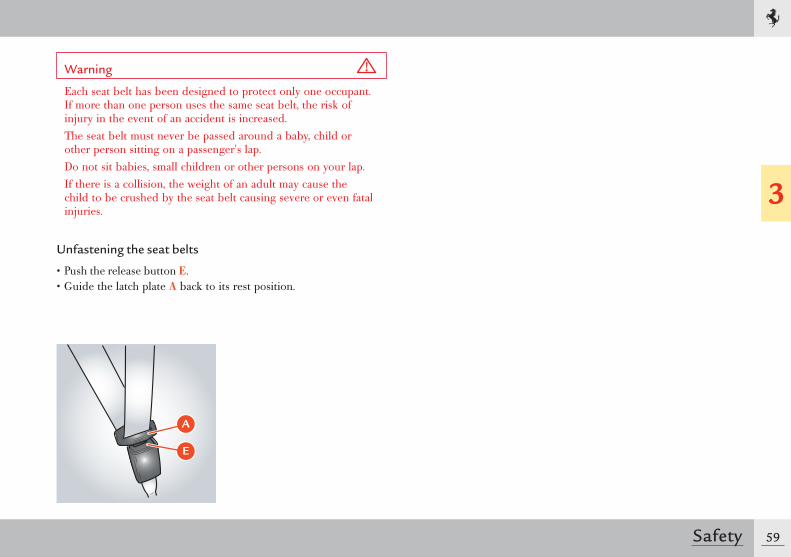
Unfastening the seat belts
• Push the release button E.• Guide the latch plate A back to its rest position.
A
E
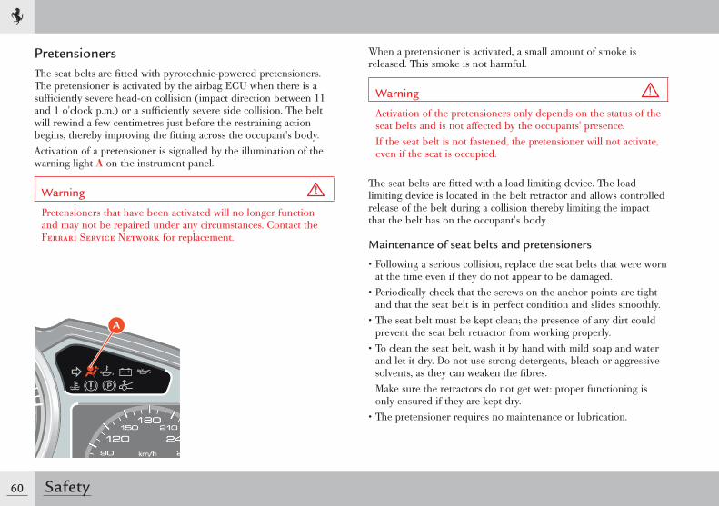
60 Safety
PretensionersThe seat belts are fi tted with pyrotechnic-powered pretensioners. The pretensioner is activated by the airbag ECU when there is a suffi ciently severe head-on collision (impact direction between 11 and 1 o'clock p.m.) or a suffi ciently severe side collision. The belt will rewind a few centimetres just before the restraining action begins, thereby improving the fi tting across the occupant's body.Activation of a pretensioner is signalled by the illumination of the warning light A on the instrument panel.
Warning
Pretensioners that have been activated will no longer function and may not be repaired under any circumstances. Contact the Ferrari Service Network for replacement.
When a pretensioner is activated, a small amount of smoke is released. This smoke is not harmful.
Warning
Activation of the pretensioners only depends on the status of the seat belts and is not affected by the occupants' presence.If the seat belt is not fastened, the pretensioner will not activate, even if the seat is occupied.
The seat belts are fi tted with a load limiting device. The load limiting device is located in the belt retractor and allows controlled release of the belt during a collision thereby limiting the impact that the belt has on the occupant's body.
Maintenance of seat belts and pretensioners
• Following a serious collision, replace the seat belts that were worn at the time even if they do not appear to be damaged.
• Periodically check that the screws on the anchor points are tight and that the seat belt is in perfect condition and slides smoothly.
• The seat belt must be kept clean; the presence of any dirt could prevent the seat belt retractor from working properly.
• To clean the seat belt, wash it by hand with mild soap and water and let it dry. Do not use strong detergents, bleach or aggressive solvents, as they can weaken the fi bres.
Make sure the retractors do not get wet: proper functioning is only ensured if they are kept dry.
• The pretensioner requires no maintenance or lubrication.
A
61
3
Safety
If immersed in water or mud, it must be replaced.• Pretensioners must be replaced at regular intervals as indicated in
the “Warranty Booklet”.
Important note
All work on any part of this safety system must be performed by the Ferrari Service Network.
Warning
Removing or making modifications of any kind to the seat belts, belt retractors and pretensioners is not allowed.Maintenance work involving strong impacts, vibrations or heating of the pretensioner area may activate them; vibrations caused by road bumps will not have this effect.
62 Safety
Auxiliary Occupant Protection Systems
Warning
Auxiliary Occupant Protection Systems are not a substitute for seat belts but increase their efficiency. Correct use of the seat belts, with the supplementary action of the Auxiliary Occupant Protection Systems, offers maximum protection in the event of a head-on collision or vehicle roll-over.
Auxiliary Occupant Protection System components
The Auxiliary Occupant Protection System components are:- Seat with built-in headrest.- Dual-stage front driver's airbag.- Dual-stage front passenger airbag.- Driver's head protection side airbag (head bag).- Passenger head protection side airbag (head bag).- Driver's seat belt (3-point with pretensioner and an automatic
system that reduces the force applied to the occupant).- Passenger seat belt (3-point with pretensioner and an automatic
system that reduces the force applied to the occupant).- Electronic Control Unit (ECU).- Additional sensors.- Instrument panel warning light.- Deformable body.
The front driver's airbag and front passenger airbag have been designed to increase the level of protection given by the seat belts in the event of a head-on collision (see page 61).The driver's head protection side airbag and passenger head protection side airbag have been designed to increase the level of protection given by the seat belts in the event of a side collision and are placed between the occupant’s head and external structures which could penetrate the passenger compartment and cause injury (see page 66).
63
3
Safety
Warning
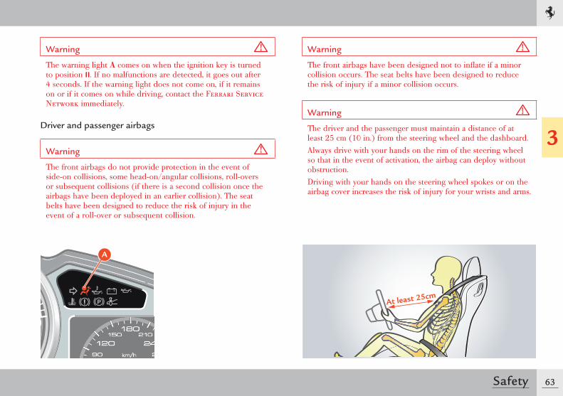
The warning light A comes on when the ignition key is turned to position II. If no malfunctions are detected, it goes out after 4 seconds. If the warning light does not come on, if it remains on or if it comes on while driving, contact the Ferrari Service Network immediately.
Driver and passenger airbags
Warning
The front airbags do not provide protection in the event of side-on collisions, some head-on/angular collisions, roll-overs or subsequent collisions (if there is a second collision once the airbags have been deployed in an earlier collision). The seat belts have been designed to reduce the risk of injury in the event of a roll-over or subsequent collision.
Warning
The front airbags have been designed not to infl ate if a minor collision occurs. The seat belts have been designed to reduce the risk of injury if a minor collision occurs.
Warning
The driver and the passenger must maintain a distance of at least 25 cm (10 in.) from the steering wheel and the dashboard.Always drive with your hands on the rim of the steering wheel so that in the event of activation, the airbag can deploy without obstruction. Driving with your hands on the steering wheel spokes or on the airbag cover increases the risk of injury for your wrists and arms.
A
At least 25cm
64 Safety
Warning
The front passenger must be seated correctly and must avoid putting hands, feet or legs on the dashboard since if the front airbag is activated, it may cause injury to legs and prevent the airbag from working properly.
Operating
The front airbags are controlled by an ECU which activates them when there is a sufficiently severe head-on collision (direction of impact between 11 and 1 o'clock p.m.).In the event of a collision with an impact force that causes deceleration that exceeds the value set for the internal sensor, the ECU will transmit a signal to deploy the airbags. The airbags will begin to inflate, breaking the cover along the breakage line and will deploy completely in a few tenths of milliseconds. Once deployed, they will serve as protection between the driver and/or passenger and structures that could cause injury.The airbags deflate immediately afterwards.
Warning
The driver and passenger should not carry objects (drink cans or bottles, pipes, etc.) that may cause injury if the airbags are activated.Persons, animals or items must not be placed between the airbags and the occupant.
Environment
When the system is activated, gases are released in the form of fumes, together with the gas used for inflating the airbags. These gases are not harmful.
The driver's airbag has been designed to be deployed according to the following strategy:• For low severity crashes, the airbag control unit will not deploy
the airbag.• For crashes of higher severity, the control unit will deploy the
driver airbag in low energy mode.• For crashes of even higher severity, the control unit will deploy
the driver airbag in high energy mode.The passenger airbag has been designed to be deployed according to the following strategy:• For low severity crashes, the airbag control unit will not deploy
the airbag.• For crashes of higher severity, the control unit will deploy the
passenger airbag in low energy mode.• For crashes of even higher severity, the control unit will deploy
the passenger airbag in high energy mode.
Warning
The driver and passenger must always fasten their seat belts and sit in an upright position, as far as possible away from the airbag, in order to have optimal protection in all types of collision.
65
3
Safety
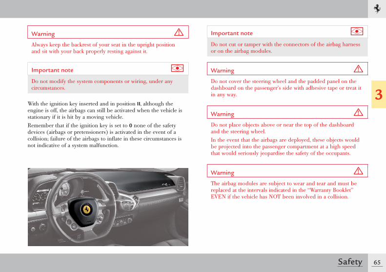
Warning
Always keep the backrest of your seat in the upright position and sit with your back properly resting against it.
Important note
Do not modify the system components or wiring, under any circumstances.
With the ignition key inserted and in position II, although the engine is off, the airbags can still be activated when the vehicle is stationary if it is hit by a moving vehicle. Remember that if the ignition key is set to 0 none of the safety devices (airbags or pretensioners) is activated in the event of a collision; failure of the airbags to inflate in these circumstances is not indicative of a system malfunction.
Important note
Do not cut or tamper with the connectors of the airbag harness or on the airbag modules.
Warning
Do not cover the steering wheel and the padded panel on the dashboard on the passenger’s side with adhesive tape or treat it in any way.
Warning
Do not place objects above or near the top of the dashboard and the steering wheel.In the event that the airbags are deployed, these objects would be projected into the passenger compartment at a high speed that would seriously jeopardise the safety of the occupants.
Warning
The airbag modules are subject to wear and tear and must be replaced at the intervals indicated in the “Warranty Booklet” EVEN if the vehicle has NOT been involved in a collision.
66 Safety
Warning
Do not modify the airbag modules in any way (indicated in the relevant picture). Do not damage the airbag modules (for example pinning something onto them or pressing objects against their covers).If, for any reason, an airbag cover gets damaged, have the airbag module immediately checked by the Ferrari Service Network.Activation of a damaged module could cause serious or fatal injuries.
Important note
Do not remove or dismantle parts of the steering wheel, dashboard or door panels; if necessary, this procedure should only be performed by a Ferrari Service Network Centre.
Important note
All the airbag system components must be replaced after an accident that caused airbag deployment.
Important note
Following an accident not involving airbag deployment, contact the Ferrari Service Network to have the system checked and any system components that may be damaged or malfunctioning replaced.
Important note
The airbag system components have been specially designed only for this specific vehicle model. Do not use them on a different vehicle model, as this may cause serious damage and consequent injury, even fatal, to the occupants in the event of an accident.
Warning
Damaged or defective components of the airbag system cannot be repaired and must be replaced.Incorrect operations performed on the system components may cause failures or accidental deployment or failure of the airbags to inflate with consequent damage and injury, even fatal.
Environment
To scrap the vehicle, please contact the Ferrari Service Network to have the airbag system deactivated.
67
3
Safety
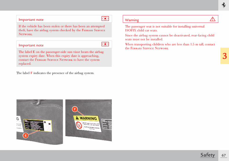
Important note
If the vehicle has been stolen or there has been an attempted theft, have the airbag system checked by the Ferrari Service Network.
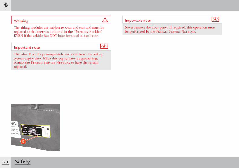
Important note
The label E on the passenger-side sun visor bears the airbag system expiry date. When this expiry date is approaching, contact the Ferrari Service Network to have the system replaced.
The label F indicates the presence of the airbag system.
F
E
Warning
The passenger seat is not suitable for installing universal ISOFIX child car seats.Since the airbag system cannot be deactivated, rear-facing child seats must not be installed.When transporting children who are less than 1.5 m tall, contact the Ferrari Service Network.
68 Safety
Side airbags
Warning
Airbags are not a substitute for seat belts, but they increase their effi ciency. Correct use of seat belts, with the supplementary action of the side airbags, offers maximum protection in the event of a collision or vehicle roll-over.
Side airbag system components
Warning
The side airbags fi tted on the vehicle have not been designed to reduce the risk of being thrown out in the event of vehicle roll-overs.
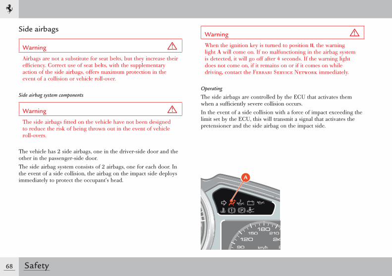
The vehicle has 2 side airbags, one in the driver-side door and the other in the passenger-side door.The side airbag system consists of 2 airbags, one for each door. In the event of a side collision, the airbag on the impact side deploys immediately to protect the occupant’s head.
Warning
When the ignition key is turned to position II, the warning light A will come on. If no malfunctioning in the airbag system is detected, it will go off after 4 seconds. If the warning light does not come on, if it remains on or if it comes on while driving, contact the Ferrari Service Network immediately.
Operating
The side airbags are controlled by the ECU that activates them when a suffi ciently severe collision occurs.In the event of a side collision with a force of impact exceeding the limit set by the ECU, this will transmit a signal that activates the pretensioner and the side airbag on the impact side.
A
69
3
Safety
The airbag will start inflating, opening its cover along the breaking line, until it is fully deployed (in a few hundredths of seconds). After deployment, the side airbag will be positioned as a protection between the driver’s or passenger’s head and the external structures which could penetrate the passenger compartment and cause injury. The airbags deflate immediately afterwards.Side airbag activation is not affected by the passenger's height or weight. The side bag is activated whenever the airbag ECU detects a collision of a sufficient impact force for deployment.
Warning
Never drive with your head out of the window as this places your head and neck in the airbag deployment area. In the event of a side-on collision, this position increases the risk of being thrown out of the vehicle and compromises the protective effect of the side airbags.
Warning
Never place an object over or near the airbag covers.In the event that the airbags are deployed, these objects would be projected into the passenger compartment at such high speed as to seriously jeopardise the safety of the occupants.
Warning
Never modify the airbag modules. Do not damage the airbag modules or the trim panels covering (upper area of door panel), by pinning objects onto them or pressing objects against their respective covers, for example.If, for any reason, an airbag cover gets damaged, have the airbag module immediately checked by the Ferrari Service Network.Activation of a damaged module could cause serious injuries.
Important note
Please consider that the airbag ECU is not capable of automatically detecting damages involving the airbag covers.Do not cover the upper part of the driver-door and passenger-door panels with adhesive tape or material and do not treat them in any way.
Warning
After deployment, the airbag components can no longer offer any protection; therefore, they cannot be repaired and must be replaced. After activation of a side airbag, have it replaced by the Ferrari Service Network.
70 Safety
Warning
The airbag modules are subject to wear and tear and must be replaced at the intervals indicated in the “Warranty Booklet” EVEN if the vehicle has NOT been involved in a collision.
Important note
The label E on the passenger-side sun visor bears the airbag system expiry date. When this expiry date is approaching, contact the Ferrari Service Network to have the system replaced.
E
Important note
Never remove the door panel. If required, this operation must be performed by the Ferrari Service Network.
71
3
Safety
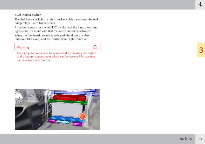
Fuel inertia switchThe fuel inertia switch is a safety device which deactivates the fuel pump relays if a collision occurs.A symbol appears on the left TFT display and the hazard warning lights come on to indicate that the switch has been activated.When the fuel inertia switch is activated, the doors are also unlocked (if locked) and the central dome light comes on.
Warning
The fuel pump relays can be reactivated by pressing the button in the battery compartment which can be accessed by opening the passenger side footrest.
72 Safety
ABS and EBDThe ABS system is a safety device which activates to prevent wheel locking if the driver presses the brake pedal too sharply, especially under low grip conditions.The system is composed of:- electro-hydraulic unit- electronic brake-force distribution EBD- four speed sensors on the wheels, incorporated in the bearings- the entire ESP sensor system (steering angle sensor,
accelerometer, yaw sensor, etc.).These features add to the vehicle’s standard braking system, without changing its characteristics.
Important note
When the ABS system is active, during emergency braking or in poor grip conditions, a “pulsing” sensation will be felt through the brake pedal. Hold the brake pedal down to continue the braking action.
When one of the wheels starts locking, the hydraulic control unit controls the braking circuit by running a 3-phase cycle:- reduction (if necessary)- maintenance- pressure increase in the hydraulic circuit.
In the event of ABS activation under braking, these regulation cycles will be repeated until the car comes to a stop or pressure on the brake pedal is reduced.In addition, the system offers the following advantages:- Driving stability (no skidding): even in the event of sharp braking
approaching wheel locking.- Manoeuvrability (no side-skidding on sharp turns).This means that even when an emergency situation requires sudden braking, the driver can avoid obstacles, or brake on a curve, without affecting the vehicle stability.
Warning
ABS system performance remains unaltered as long as the speed limit for the tyre side grip is not exceeded. If this limit is exceeded, vehicle skidding cannot be avoided.
- Optimal braking distance: depending on the type of road surface, the braking distance may be reduced by as much as 40%.
Warning
The ABS system does NOT exempt the driver from driving carefully and responsibly at all times.
73
3
Safety
Important note
The ABS system cannot compensate for driving too fast for traffic or road conditions, worn tyres, worn braking system components or driving errors.
The ABS system has been designed for the sole purpose of assisting the driver in controlling braking under extreme conditions in which he/she could instinctively cause the wheels to lock.
FBP - Ferrari Brake PrefillBrake design parameters provide a set distance between the brake pads and discs (the “air gap”): as soon as the brake pedal is pressed, the presence of the air gap leads to a slight delay in brake response.The FBP (Ferrari Brake Prefill) system eliminates the air gap by applying slight pressure to the braking system as soon as the accelerator pedal is released just before braking. This results in more immediate brake response and reduces braking distance during emergency braking thereby improving safety.
ESC - Electronic Stability ControlThe ESC system consists of two main systems:VDC Vehicle Dynamics Control, performed through the
braking systemF1-Trac traction control, performed through engine torque
modulation, depending on maximum grip on the roadand secondary systems that are always active such as the ABS and EBD.
To provide optimal control in different driving and grip conditions, four different settings have been developed:
- Level 1: (Manettino set to WET) ensures stability and maximises traction on every type of road surface, both in low and very low grip conditions, by means of engine and brake control (in this condition, the standard ASR system is activated instead of the F1-Trac function).
- Level 2: (Manettino set to SPORT) ensures stability and maximises traction only in medium- to high-grip conditions by optimising engine and brake control.
- Level 3: (Manettino set to RACE) enhances the racing features of the vehicle by reducing engine control to a minimum and maximising brake control. This mode is designed to ensure stability on the race track in high grip conditions only.
- Level 4: (Manettino set to CT OFF) further enhances the racing style performance of the vehicle: F1-Trac traction control is deactivated whereas stability control remains active when a certain level of sideslip is exceeded. F1-Trac traction control is off. Stability is NOT ensured.
- Level 5: (Manettino set to ESC OFF) ESC off. Stability is NOT guaranteed, but all the other auxiliary systems such as the ABS, EBD and the E-Diff 3 electronic differential remain active. During braking, the VDC system remains active.
74 Safety
F1-TracF1-Trac is a traction control system that derives directly from Ferrari's expertise in F1 vehicles.F1-Trac is faster and more accurate than traditional control systems and is capable of delaying and minimising engine torque adjustments as required in order to ensure the desired trajectory.The system estimates the maximum available grip in advance, by continuously monitoring the relative wheel speed and using an auto-adaptive operating logic. Comparing this information with the vehicle dynamics model stored in the control system, F1-Trac optimises the vehicle behaviour by controlling engine torque delivery.
Important note
F1-Trac does not work when the Manettino is set to CT OFF and ESC OFF driving modes.
The main feature that distinguishes the F1-Trac system from a traditional traction control system lies in its ability to estimate grip level accurately which allows the driver to make full use of the vehicle's performance driving potential.The F1-Trac system guarantees:- maximum traction when coming out of bends;- driving stability and ease even under extreme driving conditions;- driving comfort.On this vehicle, integration of the F1-Trac and E-Diff 3 systems ensures maximum performance and stability.
E-Diff 3The vehicle is equipped with an electronic differential, working on the rear axle, which continually performs a variable check on the locking between the two axle shafts.The electronic differential system, integrated with F1-Trac traction control, is capable of improving:- performance;- directional stability of the vehicle;- active safety even when close to grip limit;- driving comfort and handling.The system is based on the analysis and forecast of vehicle performance in all possible conditions. This is done by continually monitoring the pressure of the clutch actuator on the differential.The input signals are the dynamic parameters of the vehicle that the control system translates into a torque difference between the two driving wheels.On bends, the electronic differential can:- stabilise the vehicle when the accelerator pedal is released by
locking the rear axle;- control vehicle dynamics by locking the differential according to
lateral acceleration and vehicle speed;- maximise vehicle stability and, at the same time, acceleration on
bends by locking the differential according to lateral acceleration, speed, engaged gear and torque produced by the engine.
To obtain these results, the electronic differential system interacts with the F1-Trac, ESC and ABS systems, F1 gearbox and suspension damping control.
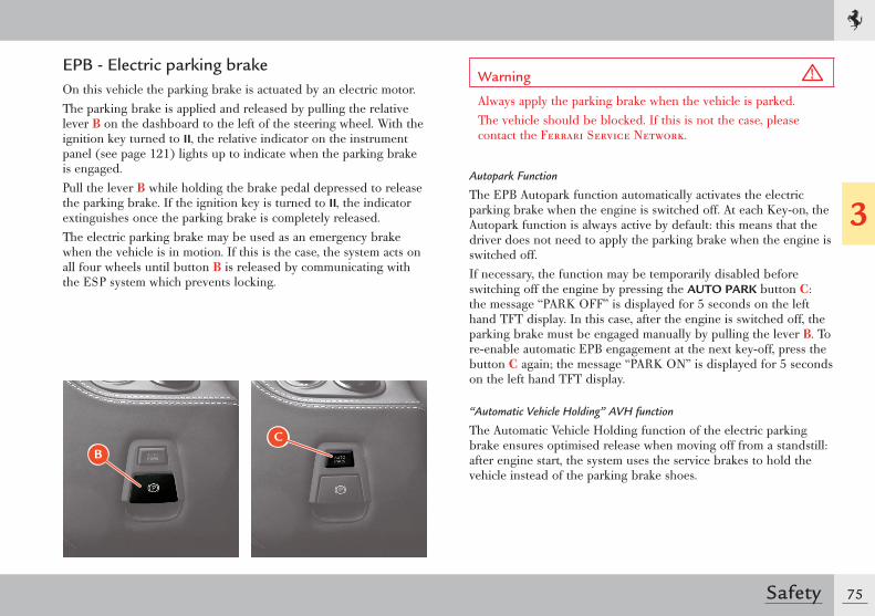
75
3
Safety
EPB - Electric parking brakeOn this vehicle the parking brake is actuated by an electric motor.The parking brake is applied and released by pulling the relative lever B on the dashboard to the left of the steering wheel. With the ignition key turned to II, the relative indicator on the instrument panel (see page 121) lights up to indicate when the parking brake is engaged.Pull the lever B while holding the brake pedal depressed to release the parking brake. If the ignition key is turned to II, the indicator extinguishes once the parking brake is completely released.The electric parking brake may be used as an emergency brake when the vehicle is in motion. If this is the case, the system acts on all four wheels until button B is released by communicating with the ESP system which prevents locking.
Warning
Always apply the parking brake when the vehicle is parked.The vehicle should be blocked. If this is not the case, please contact the Ferrari Service Network.
Autopark Function
The EPB Autopark function automatically activates the electric parking brake when the engine is switched off. At each Key-on, the Autopark function is always active by default: this means that the driver does not need to apply the parking brake when the engine is switched off.If necessary, the function may be temporarily disabled before switching off the engine by pressing the AUTO PARK button C: the message “PARK OFF” is displayed for 5 seconds on the left hand TFT display. In this case, after the engine is switched off, the parking brake must be engaged manually by pulling the lever B. To re-enable automatic EPB engagement at the next key-off, press the button C again; the message “PARK ON” is displayed for 5 seconds on the left hand TFT display.
“Automatic Vehicle Holding” AVH function
The Automatic Vehicle Holding function of the electric parking brake ensures optimised release when moving off from a standstill: after engine start, the system uses the service brakes to hold the vehicle instead of the parking brake shoes.
CB
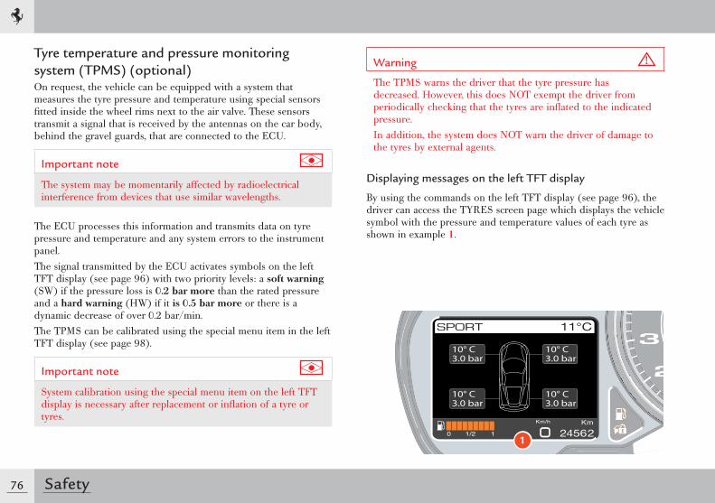
76 Safety
Tyre temperature and pressure monitoring system ( TPMS) (optional)On request, the vehicle can be equipped with a system that measures the tyre pressure and temperature using special sensors fi tted inside the wheel rims next to the air valve. These sensors transmit a signal that is received by the antennas on the car body, behind the gravel guards, that are connected to the ECU.
Important note
The system may be momentarily affected by radioelectrical interference from devices that use similar wavelengths.
The ECU processes this information and transmits data on tyre pressure and temperature and any system errors to the instrument panel.The signal transmitted by the ECU activates symbols on the left TFT display (see page 96) with two priority levels: a soft warning (SW) if the pressure loss is 0.2 bar more than the rated pressure and a hard warning (HW) if it is 0.5 bar more or there is a dynamic decrease of over 0.2 bar/min.The TPMS can be calibrated using the special menu item in the left TFT display (see page 98).
Important note
System calibration using the special menu item on the left TFT display is necessary after replacement or infl ation of a tyre or tyres.
Warning
The TPMS warns the driver that the tyre pressure has decreased. However, this does NOT exempt the driver from periodically checking that the tyres are infl ated to the indicated pressure.In addition, the system does NOT warn the driver of damage to the tyres by external agents.
Displaying messages on the left TFT display
By using the commands on the left TFT display (see page 96), the driver can access the TYRES screen page which displays the vehicle symbol with the pressure and temperature values of each tyre as shown in example 1.
1
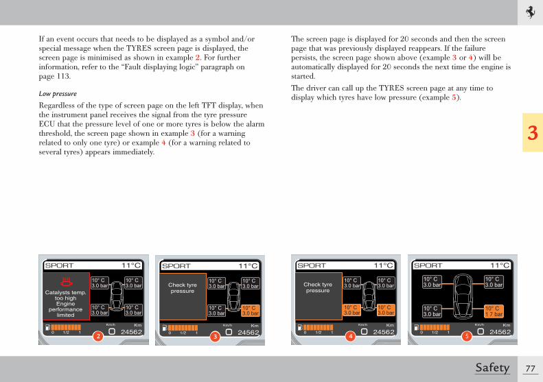
77
3
Safety
If an event occurs that needs to be displayed as a symbol and/or special message when the TYRES screen page is displayed, the screen page is minimised as shown in example 2. For further information, refer to the “Fault displaying logic” paragraph on page 113.
Low pressure
Regardless of the type of screen page on the left TFT display, when the instrument panel receives the signal from the tyre pressure ECU that the pressure level of one or more tyres is below the alarm threshold, the screen page shown in example 3 (for a warning related to only one tyre) or example 4 (for a warning related to several tyres) appears immediately.
The screen page is displayed for 20 seconds and then the screen page that was previously displayed reappears. If the failure persists, the screen page shown above (example 3 or 4) will be automatically displayed for 20 seconds the next time the engine is started.The driver can call up the TYRES screen page at any time to display which tyres have low pressure (example 5).
Catalysts temp.too highEngine
performancelimited
2
Check tyrepressure
3
Check tyrepressure
4 5
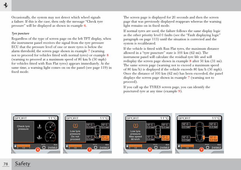
78 Safety
Occasionally, the system may not detect which wheel signals a failure. If this is the case, then only the message “Check tyre pressure” will be displayed as shown in example 6.
Tyre puncture
Regardless of the type of screen page on the left TFT display, when the instrument panel receives the signal from the tyre pressure ECU that the pressure level of one or more tyres is below the alarm threshold, the screen page shown in example 7 (warning not to proceed for vehicles fi tted with normal tyres) or example 8 (warning to proceed at a maximum speed of 80 km/h (50 mph) for vehicles fi tted with Run Flat tyres) appears immediately. At the same time, a warning light comes on on the panel (see page 119) in fi xed mode.
The screen page is displayed for 20 seconds and then the screen page that was previously displayed reappears whereas the warning light remains on in fi xed mode.If normal tyres are used, the failure follows the same display logic as the other priority level 0 faults (see the “Fault displaying logic” paragraph on page 113) until the situation is corrected and the system is recalibrated.If the vehicle is fi tted with Run Flat tyres, the maximum distance allowed in a “tyre puncture” state is 100 km (62 mi). The instrument panel will calculate the residual tyre life and will redisplay the screen page shown in example 8 after 50 km (31 mi). The same screen page (warning not to exceed a maximum speed of 80 km/h) is displayed if the vehicle exceeds 80 km/h (50 mph). Once the distance of 100 km (62 mi) has been exceeded, the panel displays the screen page shown in example 7 (warning not to proceed). If you call up the TYRES screen page, you can identify the punctured tyre at any time (example 9).
Check tyrepressure
6
Low tyrepressureDo not
proceed
7
Low tyrepressure
Max speed80 km/h
8 9
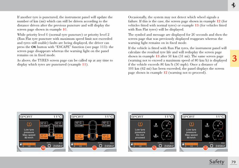
79
3
Safety
If another tyre is punctured, the instrument panel will update the number of km (mi) which can still be driven according to the distance driven after the previous puncture and will display the screen page shown in example 10.While priority level 0 (normal tyre puncture) or priority level 2 (Run Flat tyre puncture with maximum speed limit not exceeded and tyres still usable) faults are being displayed, the driver can press the OK button with “ESCAPE” function (see page 113): the screen page disappears whereas the warning light on the panel remains on in fi xed mode.As above, the TYRES screen page can be called up at any time to display which tyres are punctured (example 11).
Occasionally, the system may not detect which wheel signals a failure. If this is the case, the screen page shown in example 12 (for vehicles fi tted with normal tyres) or example 13 (for vehicles fi tted with Run Flat tyres) will be displayed.The symbol and message are displayed for 20 seconds and then the screen page that was previously displayed reappears whereas the warning light remains on in fi xed mode.If the vehicle is fi tted with Run Flat tyres, the instrument panel will calculate the residual tyre life and will redisplay the screen page shown in example 13 after 50 km (31 mi). The same screen page (warning not to exceed a maximum speed of 80 km/h) is displayed if the vehicle exceeds 80 km/h (50 mph). Once a distance of 100 km (62 mi) has been exceeded, the panel displays the screen page shown in example 12 (warning not to proceed).
Low tyrepressure
Max speed80 km/h
10 11
Low tyrepressureDo not
proceed
12
Low tyrepressure
Max speed80 km/h
13

80 Safety
System not calibrated
If the system has not been calibrated or one or more tyres have been replaced, the symbol and message shown in example 14 will be displayed. At the same time, the warning light on the instrument panel (see page 119) will fl ash for 90 seconds.When the display cycle ends (20 seconds), the symbol and message disappear and the screen page that was previously displayed reappears whereas the warning light remains on until the system has been calibrated.The TPMS can be calibrated using the special menu item in the left TFT display with the ignition key in position II and the engine off.To calibrate the TPMS, call up the MENU screen page on the left TFT display (see page 98) with the ignition key in position II and the engine off. Once the MENU screen page appears, select the items “Car setup”, “Calibr. TPMS”.
When the Menu item is displayed and the subsequent calibration accepted, the screen page shown in example 15 appears for 5 seconds.
Warning
Before calibrating the system, make sure that the tyre pressure corresponds to the indicated pressure values (see page 28). If this is not the case, the TPMS may issue wrong low pressure indications.
TPMSnot calibrated
Executecalibration
14
Calibrationactivated
Display setup
Date/Hour
Car setup
Dimming
Language/M.U.
15
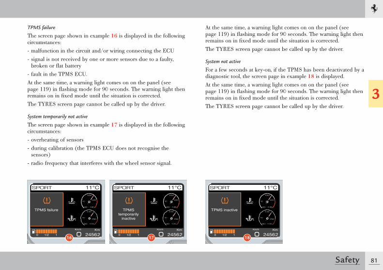
81
3
Safety
TPMS failure
The screen page shown in example 16 is displayed in the following circumstances:- malfunction in the circuit and/or wiring connecting the ECU- signal is not received by one or more sensors due to a faulty,
broken or fl at battery- fault in the TPMS ECU.At the same time, a warning light comes on on the panel (see page 119) in fl ashing mode for 90 seconds. The warning light then remains on in fi xed mode until the situation is corrected.The TYRES screen page cannot be called up by the driver.
System temporarily not active
The screen page shown in example 17 is displayed in the following circumstances:- overheating of sensors- during calibration (the TPMS ECU does not recognise the
sensors)- radio frequency that interferes with the wheel sensor signal.
At the same time, a warning light comes on on the panel (see page 119) in fl ashing mode for 90 seconds. The warning light then remains on in fi xed mode until the situation is corrected.The TYRES screen page cannot be called up by the driver.
System not active
For a few seconds at key-on, if the TPMS has been deactivated by a diagnostic tool, the screen page in example 18 is displayed.At the same time, a warning light comes on on the panel (see page 119) in fl ashing mode for 90 seconds. The warning light then remains on in fi xed mode until the situation is corrected.The TYRES screen page cannot be called up by the driver.
TPMS failure
16
TPMStemporarily
inactive
17
TPMS inactive
18
Doors ...................................................................84Engine compartment lid .........................................86Luggage compartment lid ......................................87Ignition switch .......................................................89Fuel filler flap and neck ..........................................90Power windows .....................................................92Instruments and gauges .........................................94Controls on the steering wheel ............................. 126Lighting ............................................................... 132Retractable hard top ........................................... 138Driving the vehicle ............................................... 143EPB - Electric parking brake ................................. 161Park Lock ............................................................ 163Launch Control ................................................... 164Stop&Start system (optional) ............................... 167Seat adjustment .................................................. 175Air conditioning and heating system ..................... 183Passenger compartment accessories ..................... 187
ABOUT YOUR VEHICLE
4
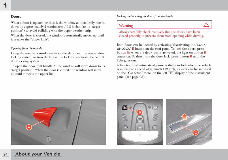
84 About your Vehicle
Doors
When a door is opened or closed, the window automatically moves down by approximately 2 centimetres / 0.8 inches (to its “target position”) to avoid colliding with the upper weather strip.When the door is closed, the window automatically moves up until it reaches the “upper limit”.
Opening from the outside
Using the remote control, deactivate the alarm and the central door locking system, or turn the key in the lock to deactivate the central door locking system.To open the door, pull handle A: the window will move down to its “target position”. When the door is closed, the window will move up until it meets the upper limit.
Locking and opening the doors from the inside
Warning
Always carefully check manually that the doors have been closed properly to prevent them from opening while driving.
Both doors can be locked by activating/deactivating the “LOCK/UNLOCK” B button on the roof panel. To lock the doors, press button B; when the door lock is activated, the light on button B comes on. To deactivate the door lock, press button B until the light goes out.A function that automatically inserts the door lock when the vehicle is moving at a speed of 20 km/h (12 mph) or over can be activated on the “Car setup” menu on the left TFT display of the instrument panel (see page 98).
C
B
�
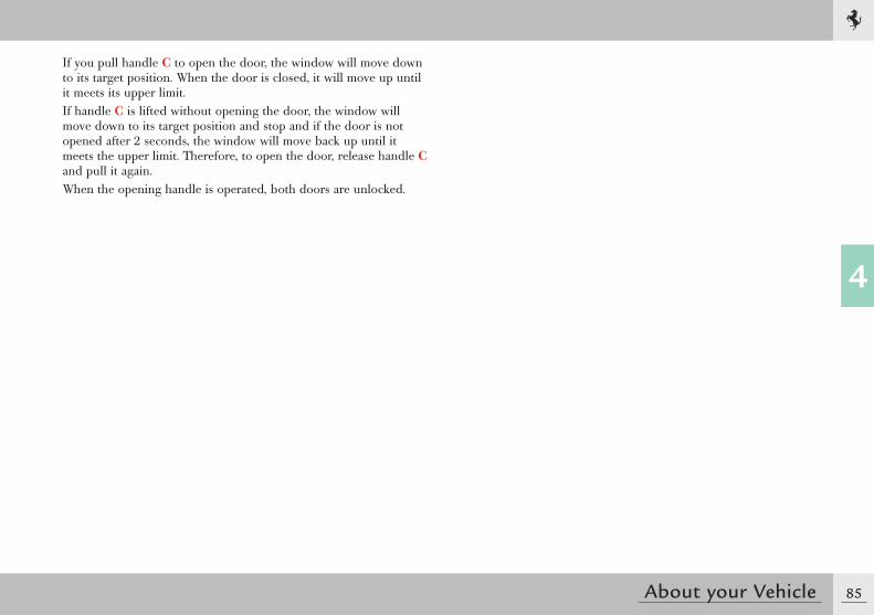
85
4
About your Vehicle
If you pull handle C to open the door, the window will move down to its target position. When the door is closed, it will move up until it meets its upper limit.If handle C is lifted without opening the door, the window will move down to its target position and stop and if the door is not opened after 2 seconds, the window will move back up until it meets the upper limit. Therefore, to open the door, release handle C and pull it again.When the opening handle is operated, both doors are unlocked.
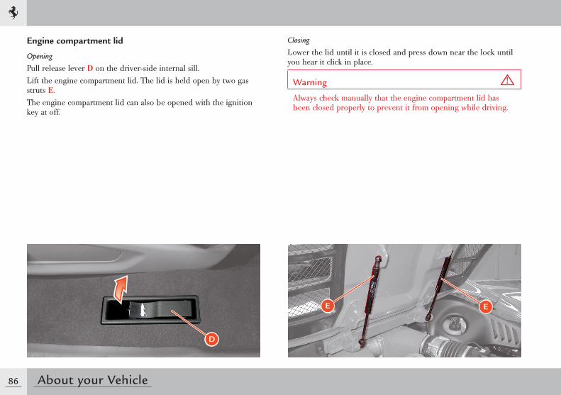
86 About your Vehicle
Engine compartment lid
Opening
Pull release lever D on the driver-side internal sill.Lift the engine compartment lid. The lid is held open by two gas struts E.The engine compartment lid can also be opened with the ignition key at off.
D
E E
Closing
Lower the lid until it is closed and press down near the lock until you hear it click in place.
Warning
Always check manually that the engine compartment lid has been closed properly to prevent it from opening while driving.
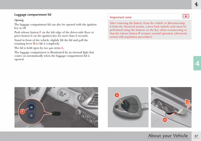
87
4
About your Vehicle
Luggage compartment lid
Opening
The luggage compartment lid can also be opened with the ignition key at off.Push release button F on the left edge of the driver-side floor or press button G on the ignition key for more than 2 seconds.Stand in front of the vehicle, slightly lift the lid and pull the retaining lever H to lift it completely.The lid is held open by two gas struts L.The luggage compartment is illuminated by an internal light that comes on automatically when the luggage compartment lid is opened.
Important note
After removing the battery from the vehicle or disconnecting it from the electrical system, a door lock/unlock cycle must be performed using the buttons on the key when reconnecting so that the release button F resumes normal operation (electronic system self-acquisition procedure).
F
G
H
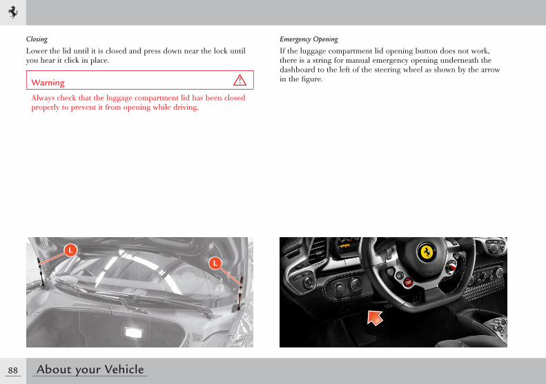
88 About your Vehicle
L
L
Closing
Lower the lid until it is closed and press down near the lock until you hear it click in place.
Warning
Always check that the luggage compartment lid has been closed properly to prevent it from opening while driving.
Emergency Opening
If the luggage compartment lid opening button does not work, there is a string for manual emergency opening underneath the dashboard to the left of the steering wheel as shown by the arrow in the figure.
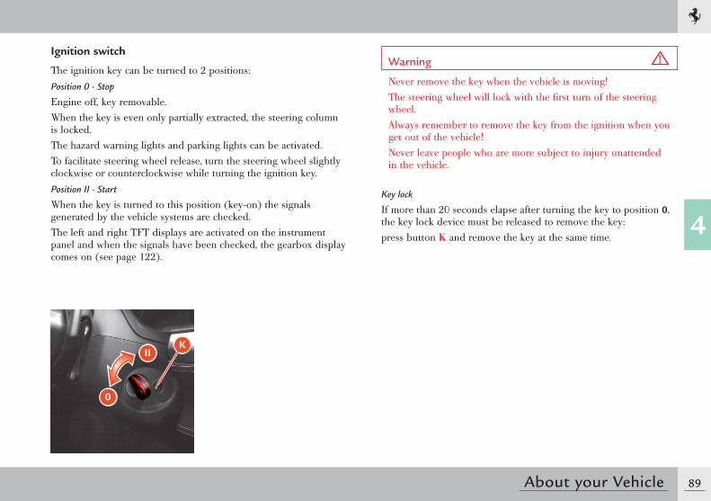
89
4
About your Vehicle
Ignition switch
The ignition key can be turned to 2 positions:Position 0 - Stop
Engine off, key removable.When the key is even only partially extracted, the steering column is locked.The hazard warning lights and parking lights can be activated.To facilitate steering wheel release, turn the steering wheel slightly clockwise or counterclockwise while turning the ignition key.Position II - Start
When the key is turned to this position (key-on) the signals generated by the vehicle systems are checked.The left and right TFT displays are activated on the instrument panel and when the signals have been checked, the gearbox display comes on (see page 122).
Warning
Never remove the key when the vehicle is moving!The steering wheel will lock with the first turn of the steering wheel.Always remember to remove the key from the ignition when you get out of the vehicle!Never leave people who are more subject to injury unattended in the vehicle.
Key lock
If more than 20 seconds elapse after turning the key to position 0, the key lock device must be released to remove the key:press button K and remove the key at the same time.
II
0
K
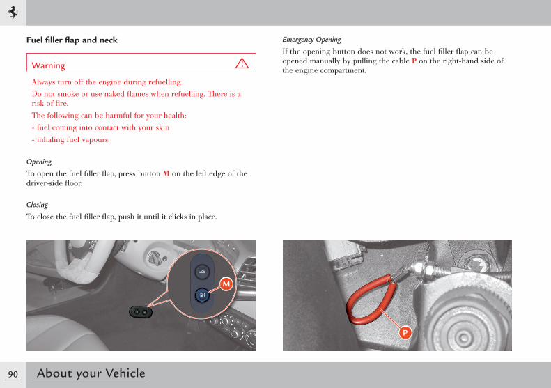
90 About your Vehicle
Fuel filler flap and neck
Warning
Always turn off the engine during refuelling.Do not smoke or use naked flames when refuelling. There is a risk of fire.The following can be harmful for your health:- fuel coming into contact with your skin- inhaling fuel vapours.
Opening
To open the fuel filler flap, press button M on the left edge of the driver-side floor.
Closing
To close the fuel filler flap, push it until it clicks in place.
M
Emergency Opening
If the opening button does not work, the fuel filler flap can be opened manually by pulling the cable P on the right-hand side of the engine compartment.
P
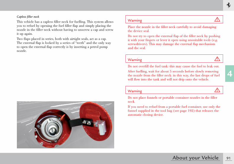
91
4
About your Vehicle
Capless filler neck
This vehicle has a capless filler neck for fuelling. This system allows you to refuel by opening the fuel filler flap and simply placing the nozzle in the filler neck without having to unscrew a cap and screw it up again.Two flaps placed in series, both with airtight seals, act as a cap. The external flap is locked by a series of “teeth” and the only way to open the external flap correctly is by inserting a petrol pump nozzle.
Warning
Place the nozzle in the filler neck carefully to avoid damaging the device seal.Do not try to open the external flap of the filler neck by pushing it with your fingers or lever it open using unsuitable tools (e.g. screwdrivers). This may damage the external flap mechanism and the seal.
Warning
Do not overfill the fuel tank: this may cause the fuel to leak out.After fuelling, wait for about 5 seconds before slowly removing the nozzle from the filler neck: in this way, the last drops of fuel will flow into the tank and will not drip onto the vehicle.
Warning
Do not place funnels or portable container nozzles in the filler neck.If you need to refuel from a portable fuel container, use only the funnel supplied in the tool bag (see page 192) that releases the automatic closing device.
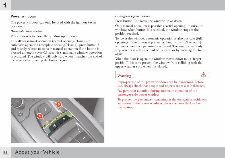
92 About your Vehicle
Power windows
The power windows can only be used with the ignition key in position II.Driver-side power window
Press button A to move the window up or down.This allows manual operation (partial opening/closing) or automatic operation (complete opening/closing): press button A and quickly release to activate manual operation; if the button is pressed at length (over 0.3 seconds), automatic window operation is activated. The window will only stop when it reaches the end of its travel or by pressing the button again.
A
B
Passenger-side power window
Press button B to move the window up or down.Only manual operation is possible (partial opening) to raise the window: when button B is released, the window stops at the position reached.To lower the window, automatic operation is also possible (full opening): if the button is pressed at length (over 0.3 seconds) automatic window operation is activated. The window will only stop when it reaches the end of its travel or by pressing the button again. When the door is open, the window moves down to its “target position”; this is to prevent the window from colliding with the upper weather strip when it is closed.
Warning
Improper use of the power windows can be dangerous. Before use, always check that people and objects are at a safe distance.Pay particular attention during automatic operation of the passenger-side power window.To protect the passengers remaining in the car against accidental activation of the power windows, always remove the key from the ignition.
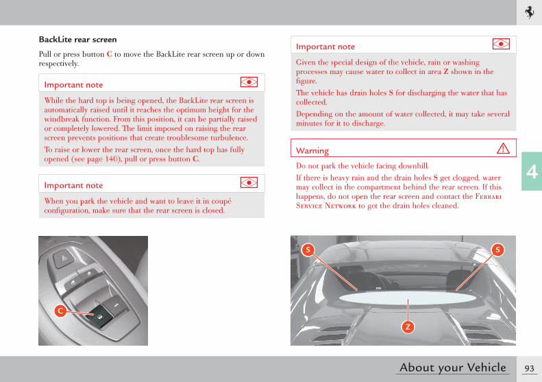
93
4
About your Vehicle
BackLite rear screen
Pull or press button C to move the BackLite rear screen up or down respectively.
Important note
While the hard top is being opened, the BackLite rear screen is automatically raised until it reaches the optimum height for the windbreak function. From this position, it can be partially raised or completely lowered. The limit imposed on raising the rear screen prevents positions that create troublesome turbulence.To raise or lower the rear screen, once the hard top has fully opened (see page 140), pull or press button C.
Important note
When you park the vehicle and want to leave it in coupé configuration, make sure that the rear screen is closed.
C
Important note
Given the special design of the vehicle, rain or washing processes may cause water to collect in area Z shown in the figure. The vehicle has drain holes S for discharging the water that has collected.Depending on the amount of water collected, it may take several minutes for it to discharge.
Warning
Do not park the vehicle facing downhill.If there is heavy rain and the drain holes S get clogged, water may collect in the compartment behind the rear screen. If this happens, do not open the rear screen and contact the Ferrari Service Network to get the drain holes cleaned.
S S
Z
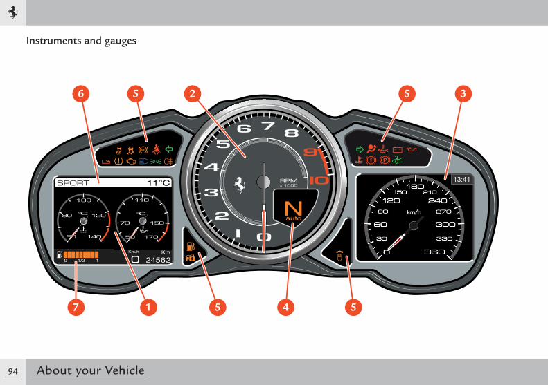
94 About your Vehicle
Instruments and gauges
6 5 2 5 3
7 1 5 4 5
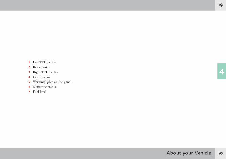
95
4
About your Vehicle
1 Left TFT display2 Rev counter3 Right TFT display4 Gear display5 Warning lights on the panel6 Manettino status7 Fuel level
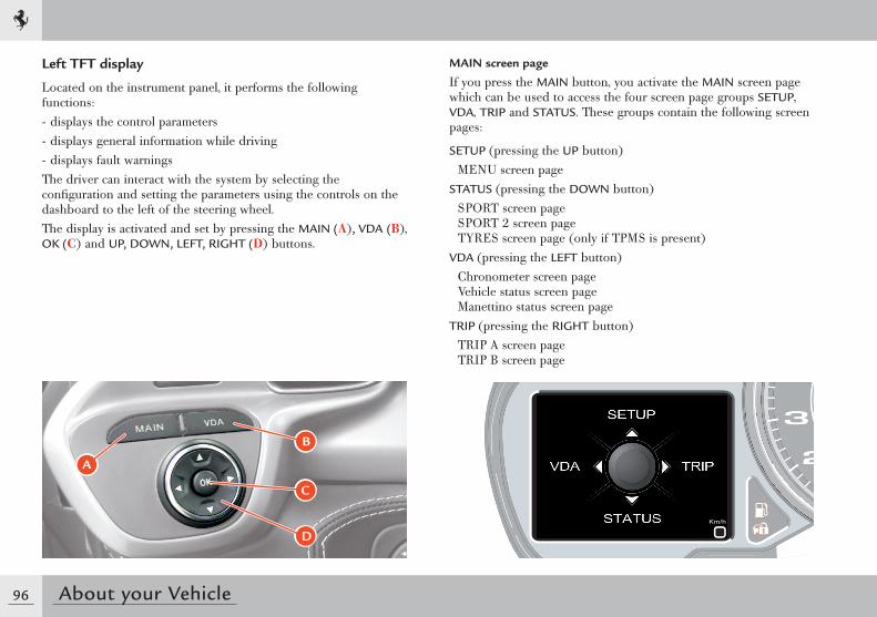
96 About your Vehicle
MAIN screen page
If you press the MAIN button, you activate the MAIN screen page which can be used to access the four screen page groups SETUP, VDA, TRIP and STATUS. These groups contain the following screen pages:
SETUP (pressing the UP button)MENU screen page
STATUS (pressing the DOWN button)SPORT screen page SPORT 2 screen page TYRES screen page (only if TPMS is present)
VDA (pressing the LEFT button)Chronometer screen pageVehicle status screen pageManettino status screen page
TRIP (pressing the RIGHT button)TRIP A screen page TRIP B screen page
Left TFT display
Located on the instrument panel, it performs the following functions:- displays the control parameters- displays general information while driving- displays fault warningsThe driver can interact with the system by selecting the confi guration and setting the parameters using the controls on the dashboard to the left of the steering wheel.The display is activated and set by pressing the MAIN (A), VDA (B), OK (C) and UP, DOWN, LEFT, RIGHT (D) buttons.
A
B
C
D
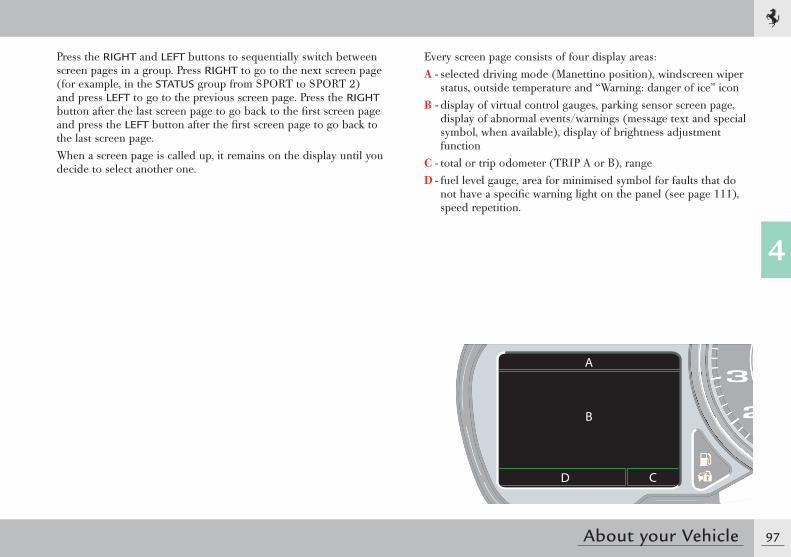
97
4
About your Vehicle
Press the RIGHT and LEFT buttons to sequentially switch between screen pages in a group. Press RIGHT to go to the next screen page (for example, in the STATUS group from SPORT to SPORT 2) and press LEFT to go to the previous screen page. Press the RIGHT button after the last screen page to go back to the fi rst screen page and press the LEFT button after the fi rst screen page to go back to the last screen page.When a screen page is called up, it remains on the display until you decide to select another one.
Every screen page consists of four display areas:A - selected driving mode (Manettino position), windscreen wiper
status, outside temperature and “Warning: danger of ice” iconB - display of virtual control gauges, parking sensor screen page,
display of abnormal events/warnings (message text and special symbol, when available), display of brightness adjustment function
C - total or trip odometer (TRIP A or B), rangeD - fuel level gauge, area for minimised symbol for faults that do
not have a specifi c warning light on the panel (see page 111), speed repetition.
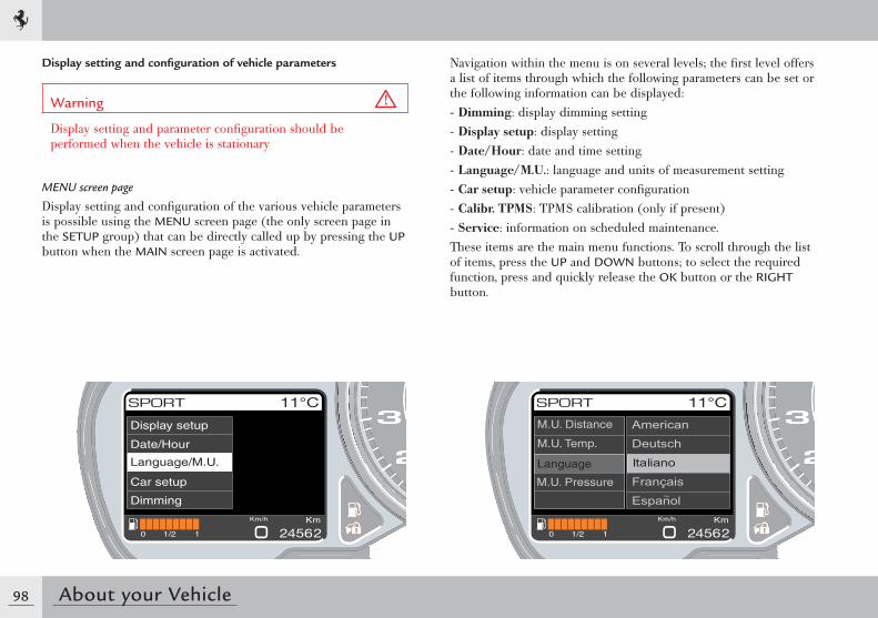
98 About your Vehicle
Navigation within the menu is on several levels; the fi rst level offers a list of items through which the following parameters can be set or the following information can be displayed:- Dimming: display dimming setting- Display setup: display setting- Date/Hour: date and time setting- Language/M.U.: language and units of measurement setting- Car setup: vehicle parameter confi guration- Calibr. TPMS: TPMS calibration (only if present)- Service: information on scheduled maintenance.These items are the main menu functions. To scroll through the list of items, press the UP and DOWN buttons; to select the required function, press and quickly release the OK button or the RIGHT button.
Language
M.U. Distance
M.U. Temp.
M.U. Pressure
Display setting and confi guration of vehicle parameters
Warning
Display setting and parameter confi guration should be performed when the vehicle is stationary
MENU screen page
Display setting and confi guration of the various vehicle parameters is possible using the MENU screen page (the only screen page in the SETUP group) that can be directly called up by pressing the UP button when the MAIN screen page is activated.
Display setup
Date/Hour
Language/M.U.
Car setup
Dimming
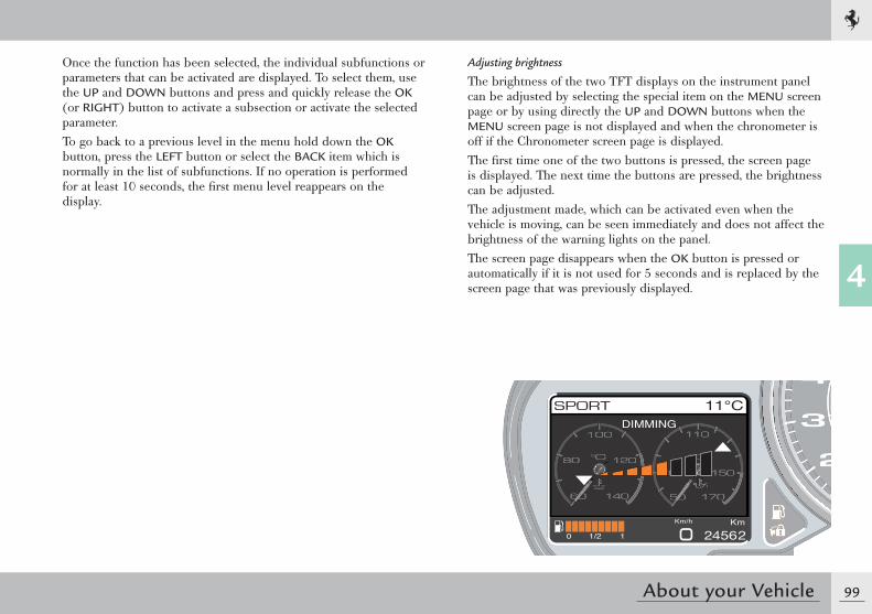
99
4
About your Vehicle
Once the function has been selected, the individual subfunctions or parameters that can be activated are displayed. To select them, use the UP and DOWN buttons and press and quickly release the OK (or RIGHT) button to activate a subsection or activate the selected parameter.To go back to a previous level in the menu hold down the OK button, press the LEFT button or select the BACK item which is normally in the list of subfunctions. If no operation is performed for at least 10 seconds, the fi rst menu level reappears on the display.
DIMMING
Adjusting brightness
The brightness of the two TFT displays on the instrument panel can be adjusted by selecting the special item on the MENU screen page or by using directly the UP and DOWN buttons when the MENU screen page is not displayed and when the chronometer is off if the Chronometer screen page is displayed.The fi rst time one of the two buttons is pressed, the screen page is displayed. The next time the buttons are pressed, the brightness can be adjusted.The adjustment made, which can be activated even when the vehicle is moving, can be seen immediately and does not affect the brightness of the warning lights on the panel.The screen page disappears when the OK button is pressed or automatically if it is not used for 5 seconds and is replaced by the screen page that was previously displayed.
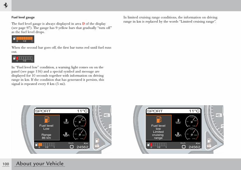
100 About your Vehicle
Fuel level gauge
The fuel level gauge is always displayed in area D of the display (see page 97). The gauge has 9 yellow bars that gradually “turn off” as the fuel level drops.
When the second bar goes off, the fi rst bar turns red until fuel runs out.
In “Fuel level low” condition, a warning light comes on on the panel (see page 116) and a special symbol and message are displayed for 10 seconds together with information on driving range in km. If the condition that has generated it persists, this signal is repeated every 8 km (5 mi).
In limited cruising range conditions, the information on driving range in km is replaced by the words “Limited cruising range”.
Fuel levelLow
Range86 km
Fuel levellow
Limitedcruising
range
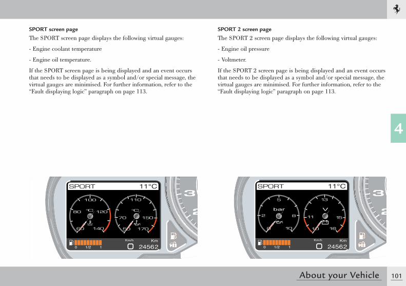
101
4
About your Vehicle
SPORT screen page
The SPORT screen page displays the following virtual gauges:
- Engine coolant temperature
- Engine oil temperature.
If the SPORT screen page is being displayed and an event occurs that needs to be displayed as a symbol and/or special message, the virtual gauges are minimised. For further information, refer to the “Fault displaying logic” paragraph on page 113.
SPORT 2 screen page
The SPORT 2 screen page displays the following virtual gauges:
- Engine oil pressure
- Voltmeter.
If the SPORT 2 screen page is being displayed and an event occurs that needs to be displayed as a symbol and/or special message, the virtual gauges are minimised. For further information, refer to the “Fault displaying logic” paragraph on page 113.
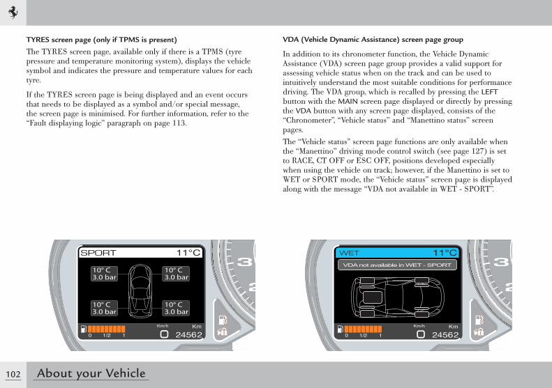
102 About your Vehicle
TYRES screen page (only if TPMS is present)
The TYRES screen page, available only if there is a TPMS (tyre pressure and temperature monitoring system), displays the vehicle symbol and indicates the pressure and temperature values for each tyre.
If the TYRES screen page is being displayed and an event occurs that needs to be displayed as a symbol and/or special message, the screen page is minimised. For further information, refer to the “Fault displaying logic” paragraph on page 113.
VDA ( Vehicle Dynamic Assistance) screen page group
In addition to its chronometer function, the Vehicle Dynamic Assistance (VDA) screen page group provides a valid support for assessing vehicle status when on the track and can be used to intuitively understand the most suitable conditions for performance driving. The VDA group, which is recalled by pressing the LEFT button with the MAIN screen page displayed or directly by pressing the VDA button with any screen page displayed, consists of the “Chronometer”, “Vehicle status” and “Manettino status” screen pages.The “Vehicle status” screen page functions are only available when the “Manettino” driving mode control switch (see page 127) is set to RACE, CT OFF or ESC OFF, positions developed especially when using the vehicle on track; however, if the Manettino is set to WET or SPORT mode, the “Vehicle status” screen page is displayed along with the message “VDA not available in WET - SPORT”.
VDA not available in WET - SPORT
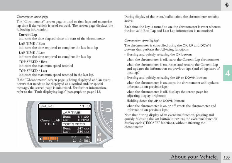
103
4
About your Vehicle
Chronometer screen page
The “Chronometer” screen page is used to time laps and memorise lap time if the vehicle is used on track. The screen page displays the following information:
Current Lapindicates the time elapsed since the start of the chronometerLAP TIME / Bestindicates the time required to complete the last best lapLAP TIME / Lastindicates the time required to complete the last lapTOP SPEED / Bestindicates the maximum speed reachedTOP SPEED / Lastindicates the maximum speed reached in the last lap.
If the “Chronometer” screen page is being displayed and an event occurs that needs to be displayed as a symbol and/or special message, the screen page is minimised. For further information, refer to the “Fault displaying logic” paragraph on page 113.
During display of the event/malfunction, the chronometer remains active.
Each time the key is turned to on, the chronometer is reset whereas the last valid Best Lap and Last Lap information is memorised.
Chronometer operating logic
The chronometer is controlled using the OK, UP and DOWN buttons that perform the following functions:- Pressing and quickly releasing the OK button:
when the chronometer is off, starts the Current Lap chronometerwhen the chronometer is on, resets and restarts the Current Lap and updates the information on previous laps (end of lap/start of next lap)
- Pressing and quickly releasing the UP or DOWN button:when the chronometer is on, stops the chronometer and updates information on previous lapswhen the chronometer is off, displays the screen page for adjusting display brightness
- Holding down the UP or DOWN button:when the chronometer is on or off, resets the chronometer and information on previous laps.
Note that during display of an event/malfunction, pressing and quickly releasing the OK button interrupts the event/malfunction display cycle (“ESCAPE” function), without affecting the chronometer.
Current LAP1:12:10
LAP TIMELAP TIME
TOP SPEEDTOP SPEED
Best: 1:11:00Last: 1:14:40
Best: 247 Km/h
Last: 230 Km/h
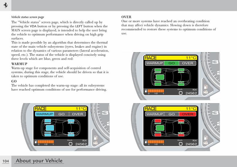
104 About your Vehicle
Vehicle status screen page
The “Vehicle status” screen page, which is directly called up by pressing the VDA button or by pressing the LEFT button when the MAIN screen page is displayed, is intended to help the user bring the vehicle to optimum performance when driving on high grip surfaces.This is made possible by an algorithm that determines the thermal state of the main vehicle subsystems (tyres, brakes and engine) in relation to the dynamics of various parameters (lateral acceleration, speed, etc.). The status of the vehicle is displayed concisely using three levels which are blue, green and red:WARMUPWarm-up stage for components and self-acquisition of control systems; during this stage, the vehicle should be driven so that it is taken to optimum conditions of use.GOThe vehicle has completed the warm-up stage: all its subsystems have reached optimum conditions of use for performance driving.
Function not availableWARMUP GO OVER
Function not availableWARMUP GO OVER
Function not availableWARMUP GO OVER
OVEROne or more systems have reached an overheating condition that may affect vehicle dynamics. Slowing down is therefore recommended to restore these systems to optimum conditions of use.
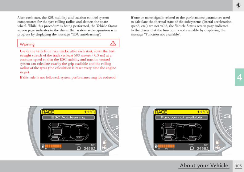
105
4
About your Vehicle
ESC Autolearning Function not available
After each start, the ESC stability and traction control system compensates for the tyre rolling radius and detects the spare wheel. While this procedure is being performed, the Vehicle Status screen page indicates to the driver that system self-acquisition is in progress by displaying the message “ESC autolearning”.
Warning
Use of the vehicle on race tracks: after each start, cover the fi rst straight stretch of the track (at least 500 meters / 0.3 mi) at a constant speed so that the ESC stability and traction control system can calculate exactly the grip available and the rolling radius of the tyres (the calculation is reset every time the engine stops).If this rule is not followed, system performance may be reduced.
If one or more signals related to the performance parameters used to calculate the thermal state of the subsystems (lateral acceleration, speed, etc.) are not valid, the Vehicle Status screen page indicates to the driver that the function is not available by displaying the message “Function not available”.
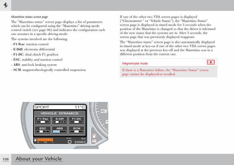
106 About your Vehicle
Manettino status screen page
The “Manettino status” screen page displays a list of parameters which can be confi gured using the “Manettino” driving mode control switch (see page 96) and indicates the confi guration each one assumes in a specifi c driving mode.The systems involved are the following:- F1-Trac: traction control- E-Diff: electronic differential- F1-DC: dual clutch F1 gearbox- ESC: stability and traction control- ABS: anti-lock braking system- SCM: magnetorheologically controlled suspension.
VEHICLE DYNAMICSVEHICLE DYNAMICS
F1-TracF1-Trac F1-DCF1-DCE-DiffE-Diff
ESCESC SCMSCMABSABS
If one of the other two VDA screen pages is displayed (“Chronometer ” or “Vehicle Status”), the “Manettino Status” screen page is displayed in timed mode for 3 seconds when the position of the Manettino is changed so that the driver is informed of the new status that the systems are in. After 3 seconds, the screen page that was previously displayed reappears.The “Manettino status” screen page is also automatically displayed in timed mode at key-on if one of the other two VDA screen pages was displayed at the previous key-off and the Manettino was in a different position from the current one.
Important note
If there is a Manettino failure, the “Manettino Status” screen page cannot be displayed or recalled.
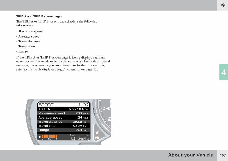
107
4
About your Vehicle
TRIP AMaximum speedAverage speedTravel distanceTravel timeRange
Mon 16 Nov263 Km/h
124 Km/h
292.8 Km
03:36 h:m
204 Km
TRIP A and TRIP B screen pages
The TRIP A or TRIP B screen page displays the following information:
- Maximum speed- Average speed- Travel distance- Travel time- Range.
If the TRIP A or TRIP B screen page is being displayed and an event occurs that needs to be displayed as a symbol and/or special message, the screen page is minimised. For further information, refer to the “Fault displaying logic” paragraph on page 113.
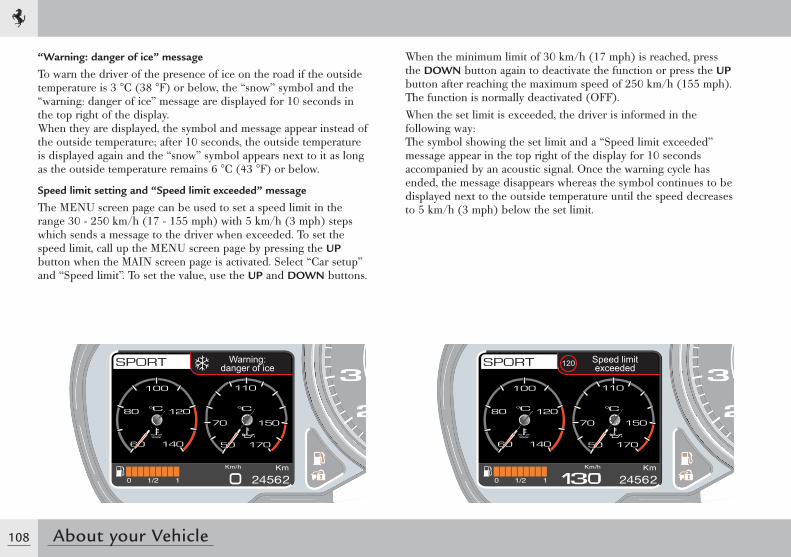
108 About your Vehicle
“Warning: danger of ice” message
To warn the driver of the presence of ice on the road if the outside temperature is 3 °C (38 °F) or below, the “snow” symbol and the “warning: danger of ice” message are displayed for 10 seconds in the top right of the display.When they are displayed, the symbol and message appear instead of the outside temperature; after 10 seconds, the outside temperature is displayed again and the “snow” symbol appears next to it as long as the outside temperature remains 6 °C (43 °F) or below.
Speed limit setting and “Speed limit exceeded” message
The MENU screen page can be used to set a speed limit in the range 30 - 250 km/h (17 - 155 mph) with 5 km/h (3 mph) steps which sends a message to the driver when exceeded. To set the speed limit, call up the MENU screen page by pressing the UP button when the MAIN screen page is activated. Select “Car setup” and “Speed limit”. To set the value, use the UP and DOWN buttons.
When the minimum limit of 30 km/h (17 mph) is reached, press the DOWN button again to deactivate the function or press the UP button after reaching the maximum speed of 250 km/h (155 mph). The function is normally deactivated (OFF).When the set limit is exceeded, the driver is informed in the following way:The symbol showing the set limit and a “Speed limit exceeded” message appear in the top right of the display for 10 seconds accompanied by an acoustic signal. Once the warning cycle has ended, the message disappears whereas the symbol continues to be displayed next to the outside temperature until the speed decreases to 5 km/h (3 mph) below the set limit.
Warning:danger of ice 120 Speed limit
exceeded
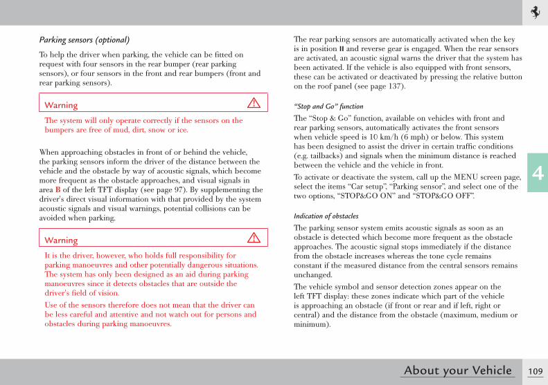
109
4
About your Vehicle
Parking sensors (optional)
To help the driver when parking, the vehicle can be fitted on request with four sensors in the rear bumper (rear parking sensors), or four sensors in the front and rear bumpers (front and rear parking sensors).
Warning
The system will only operate correctly if the sensors on the bumpers are free of mud, dirt, snow or ice.
When approaching obstacles in front of or behind the vehicle, the parking sensors inform the driver of the distance between the vehicle and the obstacle by way of acoustic signals, which become more frequent as the obstacle approaches, and visual signals in area B of the left TFT display (see page 97). By supplementing the driver's direct visual information with that provided by the system acoustic signals and visual warnings, potential collisions can be avoided when parking.
Warning
It is the driver, however, who holds full responsibility for parking manoeuvres and other potentially dangerous situations. The system has only been designed as an aid during parking manoeuvres since it detects obstacles that are outside the driver's field of vision.Use of the sensors therefore does not mean that the driver can be less careful and attentive and not watch out for persons and obstacles during parking manoeuvres.
The rear parking sensors are automatically activated when the key is in position II and reverse gear is engaged. When the rear sensors are activated, an acoustic signal warns the driver that the system has been activated. If the vehicle is also equipped with front sensors, these can be activated or deactivated by pressing the relative button on the roof panel (see page 137).
“Stop and Go” function
The “Stop & Go” function, available on vehicles with front and rear parking sensors, automatically activates the front sensors when vehicle speed is 10 km/h (6 mph) or below. This system has been designed to assist the driver in certain traffic conditions (e.g. tailbacks) and signals when the minimum distance is reached between the vehicle and the vehicle in front.To activate or deactivate the system, call up the MENU screen page, select the items “Car setup”, “Parking sensor”, and select one of the two options, “STOP&GO ON” and “STOP&GO OFF”.
Indication of obstacles
The parking sensor system emits acoustic signals as soon as an obstacle is detected which become more frequent as the obstacle approaches. The acoustic signal stops immediately if the distance from the obstacle increases whereas the tone cycle remains constant if the measured distance from the central sensors remains unchanged.The vehicle symbol and sensor detection zones appear on the left TFT display: these zones indicate which part of the vehicle is approaching an obstacle (if front or rear and if left, right or central) and the distance from the obstacle (maximum, medium or minimum).
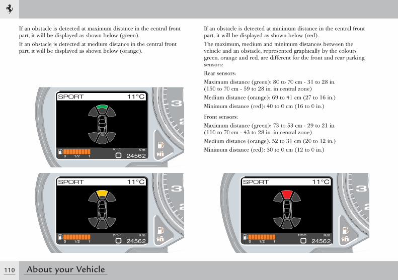
110 About your Vehicle
If an obstacle is detected at maximum distance in the central front part, it will be displayed as shown below (green).If an obstacle is detected at medium distance in the central front part, it will be displayed as shown below (orange).
If an obstacle is detected at minimum distance in the central front part, it will be displayed as shown below (red).The maximum, medium and minimum distances between the vehicle and an obstacle, represented graphically by the colours green, orange and red, are different for the front and rear parking sensors:Rear sensors:Maximum distance (green): 80 to 70 cm - 31 to 28 in. (150 to 70 cm - 59 to 28 in. in central zone)Medium distance (orange): 69 to 41 cm (27 to 16 in.)Minimum distance (red): 40 to 0 cm (16 to 0 in.)
Front sensors:Maximum distance (green): 73 to 53 cm - 29 to 21 in. (110 to 70 cm - 43 to 28 in. in central zone)Medium distance (orange): 52 to 31 cm (20 to 12 in.)Minimum distance (red): 30 to 0 cm (12 to 0 in.)
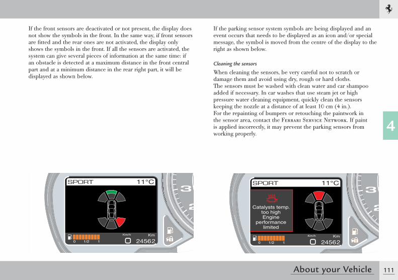
111
4
About your Vehicle
If the front sensors are deactivated or not present, the display does not show the symbols in the front. In the same way, if front sensors are fi tted and the rear ones are not activated, the display only shows the symbols in the front. If all the sensors are activated, the system can give several pieces of information at the same time: if an obstacle is detected at a maximum distance in the front central part and at a minimum distance in the rear right part, it will be displayed as shown below.
If the parking sensor system symbols are being displayed and an event occurs that needs to be displayed as an icon and/or special message, the symbol is moved from the centre of the display to the right as shown below.
Cleaning the sensors
When cleaning the sensors, be very careful not to scratch or damage them and avoid using dry, rough or hard cloths.The sensors must be washed with clean water and car shampoo added if necessary. In car washes that use steam jet or high pressure water cleaning equipment, quickly clean the sensors keeping the nozzle at a distance of at least 10 cm (4 in.).For the repainting of bumpers or retouching the paintwork in the sensor area, contact the Ferrari Service Network. If paint is applied incorrectly, it may prevent the parking sensors from working properly.
Catalysts temp.too highEngine
performancelimited

112 About your Vehicle
Indication of parking sensor failure
The system ECU checks all the components each time the reverse gear is engaged. If at least one parking sensor is faulty, the special symbol (see page 120) is displayed on the left TFT display together with the message “Parking sensor failure. Warning! Possible obstacles” accompanied by an acoustic signal.
Important note
The sensors are able to detect obstacles with reasonably large, even surfaces (e.g.: poles with diameters of over 60 mm (2.4 in.), walls, barriers, trees). Detection is not optimum with obstacles with sharp projections or uneven surfaces.
Important note
During parking manoeuvres, always take the utmost care since obstacles may be located above or below the sensors.
Important note
Objects placed close to the rear part of the vehicle are not always detected by the system and may therefore damage the vehicle or be damaged themselves.
Important note
The signals sent by the sensors may also be affected by damage to the sensors caused by dirt, snow or ice on the sensors or by ultrasound systems (e.g. pneumatic brakes on lorries or pneumatic drills) in the vicinity.
Warning
However, the driver has full responsibility for parking manoeuvres and in other potentially dangerous situations. The system has only been designed as an aid during parking manoeuvres, since it detects obstacles that are outside the driver's range of visibility.The sensors are therefore not a substitute for the driver's care and attention when parking and checking for the presence of persons or objects.
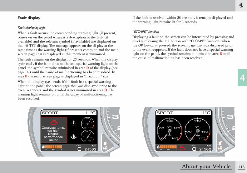
113
4
About your Vehicle
Fault display
Fault displaying logic
When a fault occurs, the corresponding warning light (if present) comes on on the panel whereas a description of the fault (if available) and the relevant symbol (if available) are displayed on the left TFT display. The message appears on the display at the same time as the warning light (if present) comes on and the main screen page that is displayed at that moment is minimised.The fault remains on the display for 20 seconds. When the display cycle ends, if the fault does not have a special warning light on the panel, the symbol remains minimised in area D of the display (see page 97) until the cause of malfunctioning has been resolved. In area B the main screen page is displayed in “maximum” size.When the display cycle ends, if the fault has a special warning light on the panel, the screen page that was displayed prior to the event reappears and the symbol is not minimised in area D. The warning light remains on until the cause of malfunctioning has been resolved.
If the fault is resolved within 20 seconds, it remains displayed and the warning light remains lit for 2 seconds.
“ESCAPE” function
Displaying a fault on the screen can be interrupted by pressing and quickly releasing the OK button with “ESCAPE” function. When the OK button is pressed, the screen page that was displayed prior to the event reappears. If the fault does not have a special warning light on the panel, the symbol remains minimised in area D until the cause of malfunctioning has been resolved.
Catalysts temp.too highEngine
performancelimited
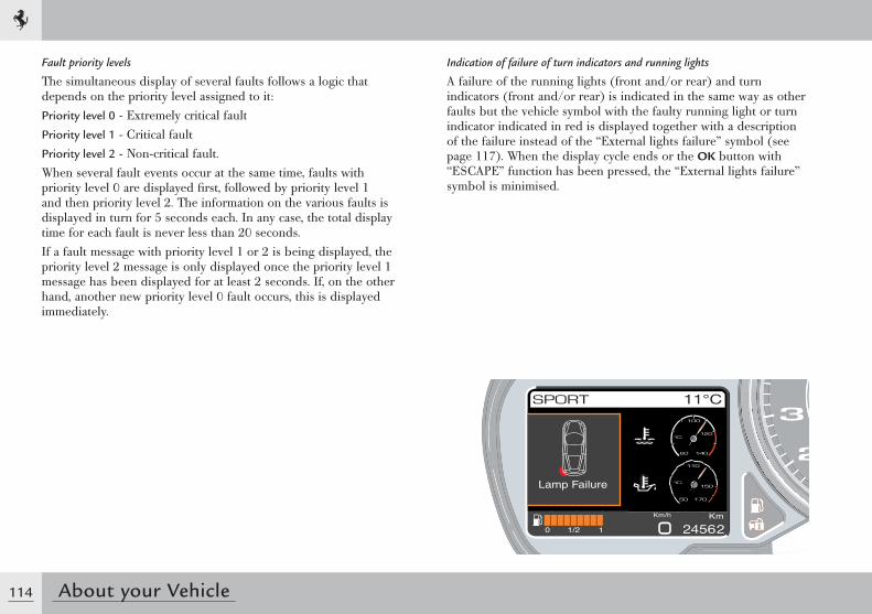
114 About your Vehicle
Fault priority levels
The simultaneous display of several faults follows a logic that depends on the priority level assigned to it:Priority level 0 - Extremely critical faultPriority level 1 - Critical faultPriority level 2 - Non-critical fault.When several fault events occur at the same time, faults with priority level 0 are displayed fi rst, followed by priority level 1 and then priority level 2. The information on the various faults is displayed in turn for 5 seconds each. In any case, the total display time for each fault is never less than 20 seconds.If a fault message with priority level 1 or 2 is being displayed, the priority level 2 message is only displayed once the priority level 1 message has been displayed for at least 2 seconds. If, on the other hand, another new priority level 0 fault occurs, this is displayed immediately.
Lamp Failure
Indication of failure of turn indicators and running lights
A failure of the running lights (front and/or rear) and turn indicators (front and/or rear) is indicated in the same way as other faults but the vehicle symbol with the faulty running light or turn indicator indicated in red is displayed together with a description of the failure instead of the “External lights failure” symbol (see page 117). When the display cycle ends or the OK button with “ESCAPE” function has been pressed, the “External lights failure” symbol is minimised.
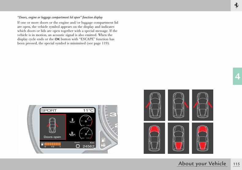
115
4
About your Vehicle
Doors open
“Doors, engine or luggage compartment lid open” function display
If one or more doors or the engine and/or luggage compartment lid are open, the vehicle symbol appears on the display and indicates which doors or lids are open together with a special message. If the vehicle is in motion, an acoustic signal is also emitted. When the display cycle ends or the OK button with “ESCAPE” function has been pressed, the special symbol is minimised (see page 119).
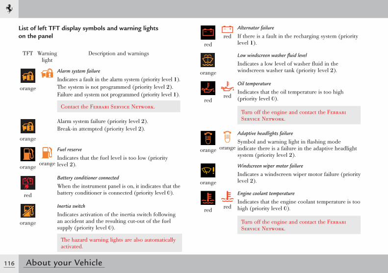
116 About your Vehicle
redred
Alternator failure
If there is a fault in the recharging system (priority level 1).
orange
Low windscreen washer fluid level
Indicates a low level of washer fluid in the windscreen washer tank (priority level 2).
redred
Oil temperature
Indicates that the oil temperature is too high (priority level 0).
Turn off the engine and contact the Ferrari Service Network.
orange orange
Adaptive headlights failure
Symbol and warning light in flashing mode indicate there is a failure in the adaptive headlight system (priority level 2).
orange
Windscreen wiper motor failure
Indicates a windscreen wiper motor failure (priority level 2).
red red
Engine coolant temperature
Indicates that the engine coolant temperature is too high (priority level 0).
Turn off the engine and contact the Ferrari Service Network.
List of left TFT display symbols and warning lights on the panel
TFT Warning light
Description and warnings
orange
Alarm system failure
Indicates a fault in the alarm system (priority level 1).The system is not programmed (priority level 2).Failure and system not programmed (priority level 1).
Contact the Ferrari Service Network.
orange
Alarm system failure (priority level 2).Break-in attempted (priority level 2).
orange orange
Fuel reserve
Indicates that the fuel level is too low (priority level 2).
red
Battery conditioner connected
When the instrument panel is on, it indicates that the battery conditioner is connected (priority level 0).
orange
Inertia switch
Indicates activation of the inertia switch following an accident and the resulting cut-out of the fuel supply (priority level 0).
The hazard warning lights are also automatically activated.
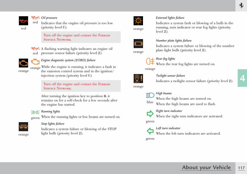
117
4
About your Vehicle
red
redOil pressure
Indicates that the engine oil pressure is too low (priority level 0).
Turn off the engine and contact the Ferrari Service Network.
redA flashing warning light indicates an engine oil pressure sensor failure (priority level 2).
orangeorange
Engine diagnostic system (EOBD) failure
While the engine is running, it indicates a fault in the emission control system and in the ignition/injection system (priority level 0).
Turn off the engine and contact the Ferrari Service Network.
After turning the ignition key to position II, it remains on for a self-check for a few seconds after the engine has started.
green
Running lights
When the running lights or low beams are turned on.
orange
Stop lights failure
Indicates a system failure or blowing of the STOP light bulb (priority level 2).
orange
External lights failure
Indicates a system fault or blowing of a bulb in the running, turn indicator or rear fog lights (priority level 2).
orange
Number plate lights failure
Indicates a system failure or blowing of the number plate light bulb (priority level 2).
orange
Rear fog lights
When the rear fog lights are turned on.
orange
Twilight sensor failure
Indicates a twilight sensor failure (priority level 2).
blue
High beams
When the high beams are turned on.When the high beams are used to flash.
green
Right turn indicator
When the right turn indicators are activated.
green
Left turn indicator
When the left turn indicators are activated.
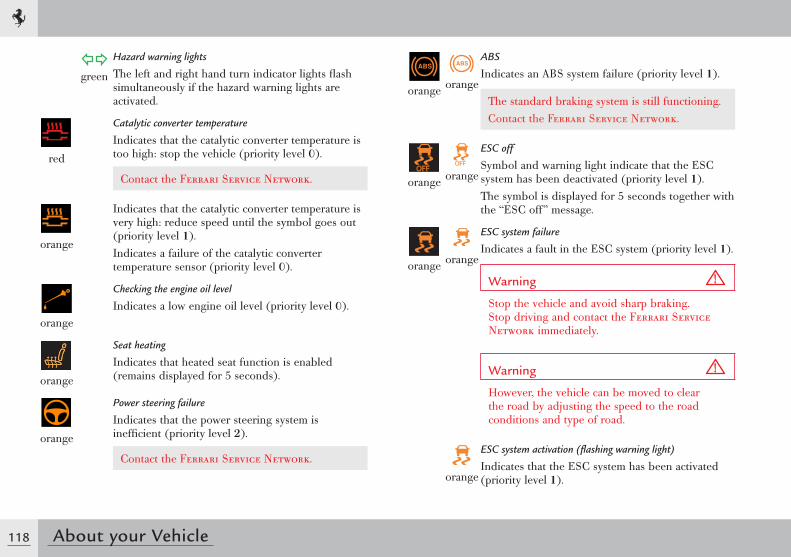
118 About your Vehicle
orange orange
ABS
Indicates an ABS system failure (priority level 1).
The standard braking system is still functioning. Contact the Ferrari Service Network.
orange orange
ESC off
Symbol and warning light indicate that the ESC system has been deactivated (priority level 1).The symbol is displayed for 5 seconds together with the “ESC off” message.
orange orange
ESC system failure
Indicates a fault in the ESC system (priority level 1).
Warning
Stop the vehicle and avoid sharp braking. Stop driving and contact the Ferrari Service Network immediately.
Warning
However, the vehicle can be moved to clear the road by adjusting the speed to the road conditions and type of road.
orange
ESC system activation (flashing warning light)
Indicates that the ESC system has been activated (priority level 1).
green
Hazard warning lights
The left and right hand turn indicator lights flash simultaneously if the hazard warning lights are activated.
red
Catalytic converter temperature
Indicates that the catalytic converter temperature is too high: stop the vehicle (priority level 0).
Contact the Ferrari Service Network.
orange
Indicates that the catalytic converter temperature is very high: reduce speed until the symbol goes out (priority level 1).Indicates a failure of the catalytic converter temperature sensor (priority level 0).
orange
Checking the engine oil level
Indicates a low engine oil level (priority level 0).
orange
Seat heating
Indicates that heated seat function is enabled (remains displayed for 5 seconds).
orange
Power steering failure
Indicates that the power steering system is inefficient (priority level 2).
Contact the Ferrari Service Network.
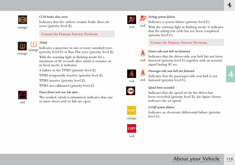
119
4
About your Vehicle
orange
CCM brake discs worn
Indicates that the carbon ceramic brake discs are worn (priority level 2).
Contact the Ferrari Service Network.
orangeorange
TPMS
Indicates a puncture in one or more standard tyres (priority level 0) or Run Flat tyres (priority level 2).With the warning light in flashing mode for a maximum of 90 seconds after which it remains on in fixed mode, it indicates:A failure in the TPMS (priority level 2).TPMS temporarily inactive (priority level 2).TPMS inactive (priority level 2).TPMS not calibrated (priority level 2).
red
Doors/front and rear lids open
The symbol, which is minimised, indicates that one or more doors and/or lids are open.
red red
Airbag system failure
Indicates a system failure (priority level 0).With the warning light in flashing mode, it indicates that the airbag test cycle has not been completed (priority level 0).
Contact the Ferrari Service Network.
red
Driver-side seat belt not fastened
Indicates that the driver-side seat belt has not been fastened (priority level 0) together with an acoustic signal lasting 90 sec.
red red
Passenger-side seat belt not fastened
Indicates that the passenger-side seat belt is not fastened (priority level 0).
Speed limit exceeded
Indicates that the speed set by the driver has been exceeded (priority level 2), the figure shown indicates the set speed.
E-DIFF
orange
E-DIFF
red
E-Diff system failure
Indicates an electronic differential failure (priority level 1).
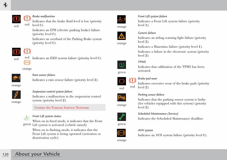
120 About your Vehicle
orange
Front Lift system failure
Indicates a Front Lift system failure (priority level 1).
orange
Generic failure
Indicates an airbag warning light failure (priority level 2).Indicates a Manettino failure (priority level 1).Indicates a failure in the electronic system (priority level 2).
green
TPMS
Indicates that calibration of the TPMS has been activated.
red red
Brake pad wear
Indicates excessive wear of the brake pads (priority level 2).
orange
Parking sensor failure
Indicates that the parking sensor system is faulty (for vehicles equipped with this system) (priority level 2).
green
Scheduled Maintenance (Service)
Indicates the Scheduled Maintenance deadline.
orange
AVH system
Indicates an AVH system failure (priority level 0).
red red
Brake malfunction
Indicates that the brake fluid level is low (priority level 0).Indicates an EPB (electric parking brake) failure (priority level 0).Indicates an overhaul of the Parking Brake system (priority level 0).
red red
orange
Indicates an EBD system failure (priority level 0).
orange
Rain sensor failure
Indicates a rain sensor failure (priority level 2).
orange
Suspension control system failure
Indicates a malfunction in the suspension control system (priority level 2).
Contact the Ferrari Service Network.
green
Front Lift system status
When on in fixed mode, it indicates that the Front Lift system is activated (vehicle raised).When on in flashing mode, it indicates that the Front Lift system is being operated (activation or deactivation cycle).
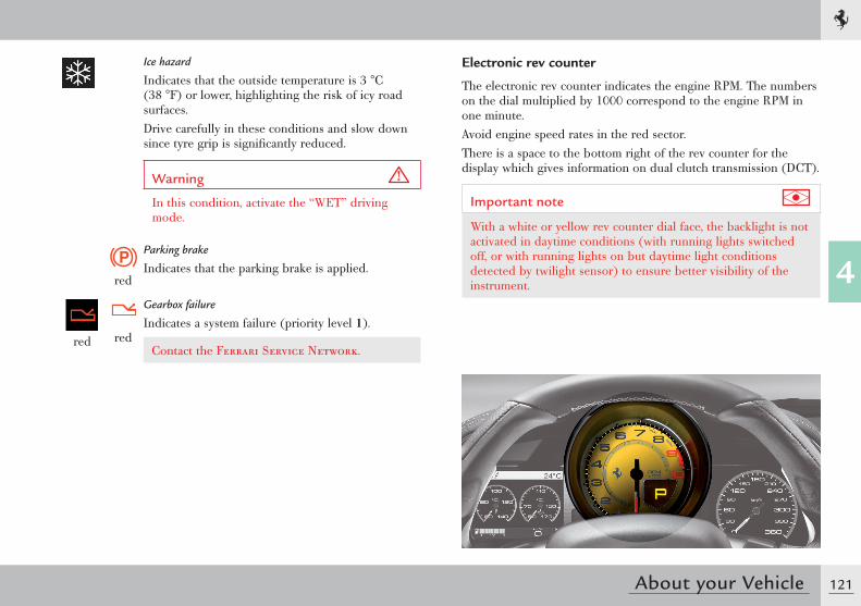
121
4
About your Vehicle
Ice hazard
Indicates that the outside temperature is 3 °C (38 °F) or lower, highlighting the risk of icy road surfaces.Drive carefully in these conditions and slow down since tyre grip is significantly reduced.
Warning
In this condition, activate the “WET” driving mode.
red
Parking brake
Indicates that the parking brake is applied.
red red
Gearbox failure
Indicates a system failure (priority level 1).
Contact the Ferrari Service Network.
Electronic rev counter
The electronic rev counter indicates the engine RPM. The numbers on the dial multiplied by 1000 correspond to the engine RPM in one minute.Avoid engine speed rates in the red sector.There is a space to the bottom right of the rev counter for the display which gives information on dual clutch transmission (DCT).
Important note
With a white or yellow rev counter dial face, the backlight is not activated in daytime conditions (with running lights switched off, or with running lights on but daytime light conditions detected by twilight sensor) to ensure better visibility of the instrument.
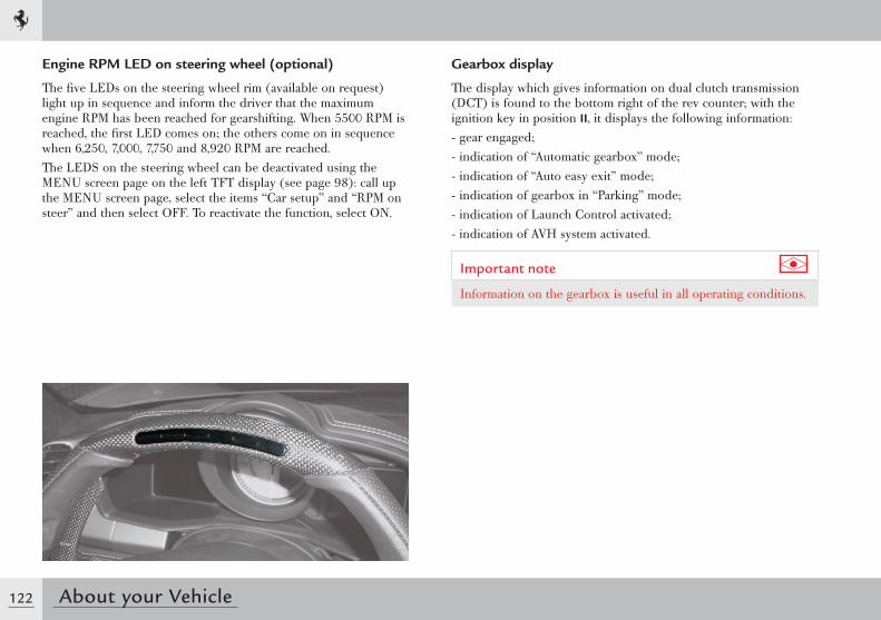
122 About your Vehicle
Gearbox display
The display which gives information on dual clutch transmission (DCT) is found to the bottom right of the rev counter; with the ignition key in position II, it displays the following information:- gear engaged;- indication of “Automatic gearbox” mode;- indication of “Auto easy exit” mode;- indication of gearbox in “Parking” mode;- indication of Launch Control activated;- indication of AVH system activated.
Important note
Information on the gearbox is useful in all operating conditions.
Engine RPM LED on steering wheel (optional)
The five LEDs on the steering wheel rim (available on request) light up in sequence and inform the driver that the maximum engine RPM has been reached for gearshifting. When 5500 RPM is reached, the first LED comes on; the others come on in sequence when 6,250, 7,000, 7,750 and 8,920 RPM are reached.The LEDS on the steering wheel can be deactivated using the MENU screen page on the left TFT display (see page 98): call up the MENU screen page, select the items “Car setup” and “RPM on steer” and then select OFF. To reactivate the function, select ON.
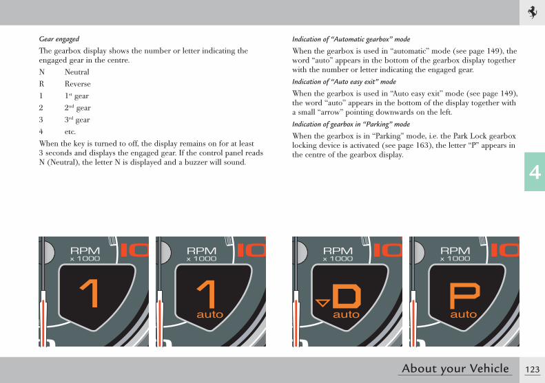
123
4
About your Vehicle
Gear engaged
The gearbox display shows the number or letter indicating the engaged gear in the centre.N NeutralR Reverse1 1st gear2 2nd gear3 3rd gear4 etc.When the key is turned to off, the display remains on for at least 3 seconds and displays the engaged gear. If the control panel reads N (Neutral), the letter N is displayed and a buzzer will sound.
Indication of “Automatic gearbox” mode
When the gearbox is used in “automatic” mode (see page 149), the word “auto” appears in the bottom of the gearbox display together with the number or letter indicating the engaged gear.Indication of “Auto easy exit” mode
When the gearbox is used in “Auto easy exit” mode (see page 149), the word “auto” appears in the bottom of the display together with a small “arrow” pointing downwards on the left.Indication of gearbox in “Parking” mode
When the gearbox is in “Parking” mode, i.e. the Park Lock gearbox locking device is activated (see page 163), the letter “P” appears in the centre of the gearbox display.
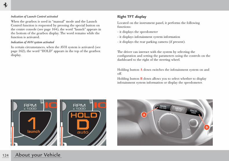
124 About your Vehicle
Indication of Launch Control activated
When the gearbox is used in “manual” mode and the Launch Control function is requested by pressing the special button on the centre console (see page 164), the word “launch” appears in the bottom of the gearbox display. The word remains while the function is activated.Indication of AVH system activated
In certain circumstances, when the AVH system is activated (see page 162), the word “HOLD” appears in the top of the gearbox display.
Right TFT display
Located on the instrument panel, it performs the following functions:- it displays the speedometer- it displays infotainment system information- it displays the rear parking camera (if present).
The driver can interact with the system by selecting the configuration and setting the parameters using the controls on the dashboard to the right of the steering wheel.
Holding button A down switches the infotainment system on and off.Holding button B down allows you to select whether to display infotainment system information or display the speedometer.
B
A
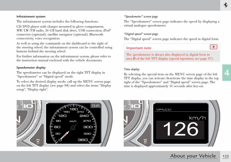
125
4
About your Vehicle
126
Infotainment system
The infotainment system includes the following functions:CD/DVD player with charger mounted in glove compartment, MW/LW/FM radio, 30 GB hard disk drive, USB connection, iPod® connector (optional), satellite navigator (optional), Bluetooth connectivity, voice recognition.As well as using the commands on the dashboard to the right of the steering wheel, the infotainment system can be controlled using buttons behind the steering wheel.For further information on the infotainment system, please refer to the instruction manual enclosed with the vehicle documents.
Speedometer display
The speedometer can be displayed on the right TFT display in “Speedometer” or “Digital speed” mode.To select the desired display mode, call up the MENU screen page on the left TFT display (see page 98) and select the items “Display setup”, “Display right”.
“Speedometer” screen page
The “Speedometer” screen page indicates the speed by displaying a virtual analogue speedometer.
“Digital speed” screen page
The “Digital speed” screen page indicates the speed in digital form.
Important note
The speedometer is always also displayed in digital form in area D of the left TFT display (speed repetition, see page 97).
Time display
By selecting the special item on the MENU screen page of the left TFT display, you can activate/deactivate the time display in the top right of the “Speedometer” and “Digital speed” screen page. The time is displayed approximately 10 seconds after key-on.
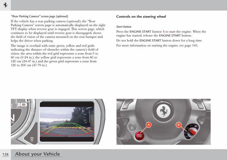
126 About your Vehicle
Controls on the steering wheel
Start button
Press the ENGINE START button A to start the engine. When the engine has started, release the ENGINE START button.Do not hold the ENGINE START button down for a long time.For more information on starting the engine, see page 145.
A B
“ Rear Parking Camera” screen page (optional)
If the vehicle has a rear parking camera (optional), the “Rear Parking Camera” screen page is automatically displayed on the right TFT display when reverse gear is engaged. This screen page, which continues to be displayed until reverse gear is disengaged, shows the fi eld of vision of the camera mounted on the rear bumper and helps the driver when parking.The image is overlaid with static green, yellow and red grids indicating the distance of obstacles within the camera's fi eld of vision. the area within the red grid represents a zone from 0 to 60 cm (0-24 in.), the yellow grid represents a zone from 60 to 120 cm (24-47 in.) and the green grid represents a zone from 120 to 200 cm (47-79 in.).
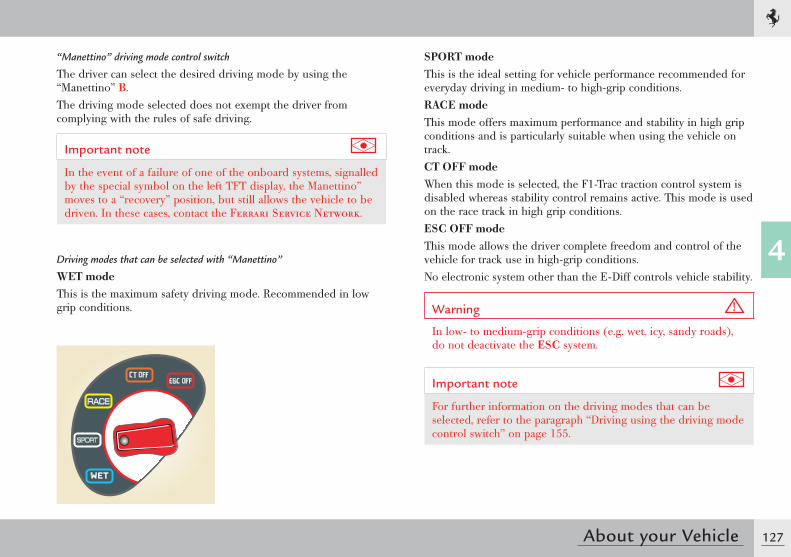
127
4
About your Vehicle
SPORT modeThis is the ideal setting for vehicle performance recommended for everyday driving in medium- to high-grip conditions.RACE modeThis mode offers maximum performance and stability in high grip conditions and is particularly suitable when using the vehicle on track.CT OFF modeWhen this mode is selected, the F1-Trac traction control system is disabled whereas stability control remains active. This mode is used on the race track in high grip conditions.ESC OFF modeThis mode allows the driver complete freedom and control of the vehicle for track use in high-grip conditions.No electronic system other than the E-Diff controls vehicle stability.
Warning
In low- to medium-grip conditions (e.g. wet, icy, sandy roads), do not deactivate the ESC system.
Important note
For further information on the driving modes that can be selected, refer to the paragraph “Driving using the driving mode control switch” on page 155.
“Manettino” driving mode control switch
The driver can select the desired driving mode by using the “Manettino” B.The driving mode selected does not exempt the driver from complying with the rules of safe driving.
Important note
In the event of a failure of one of the onboard systems, signalled by the special symbol on the left TFT display, the Manettino” moves to a “recovery” position, but still allows the vehicle to be driven. In these cases, contact the Ferrari Service Network.
Driving modes that can be selected with “Manettino”
WET modeThis is the maximum safety driving mode. Recommended in low grip conditions.
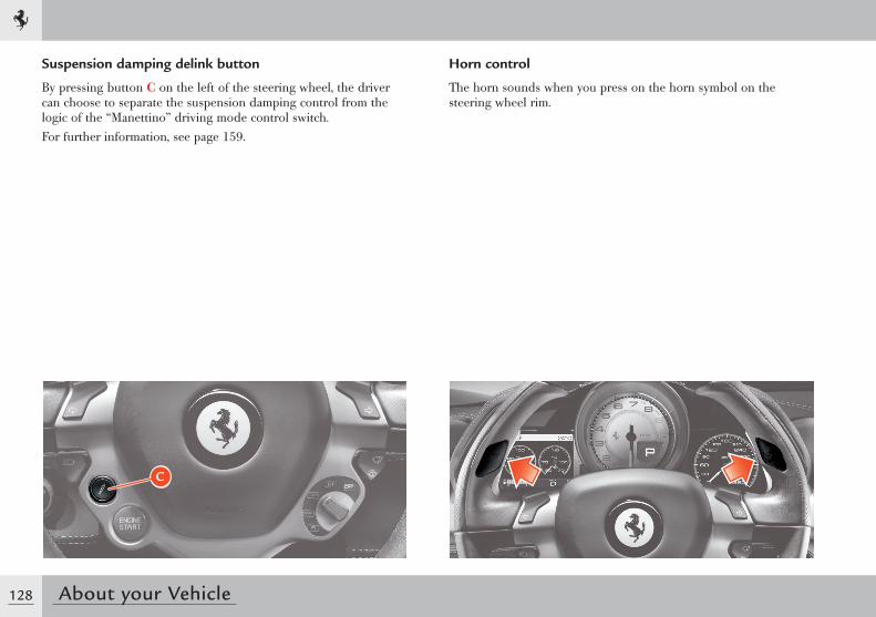
128 About your Vehicle
Horn control
The horn sounds when you press on the horn symbol on the steering wheel rim.
Suspension damping delink button
By pressing button C on the left of the steering wheel, the driver can choose to separate the suspension damping control from the logic of the “Manettino” driving mode control switch.For further information, see page 159.
C
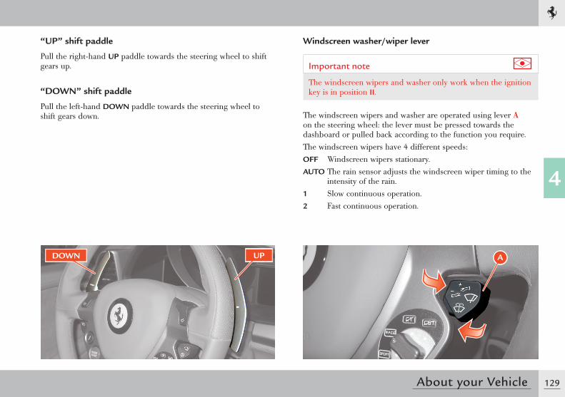
129
4
About your Vehicle
DOWN UP
“UP” shift paddle
Pull the right-hand UP paddle towards the steering wheel to shift gears up.
“DOWN” shift paddle
Pull the left-hand DOWN paddle towards the steering wheel to shift gears down.
Windscreen washer/wiper lever
Important note
The windscreen wipers and washer only work when the ignition key is in position II.
The windscreen wipers and washer are operated using lever A on the steering wheel: the lever must be pressed towards the dashboard or pulled back according to the function you require.The windscreen wipers have 4 different speeds:OFF Windscreen wipers stationary.AUTO The rain sensor adjusts the windscreen wiper timing to the
intensity of the rain.1 Slow continuous operation.2 Fast continuous operation.
A
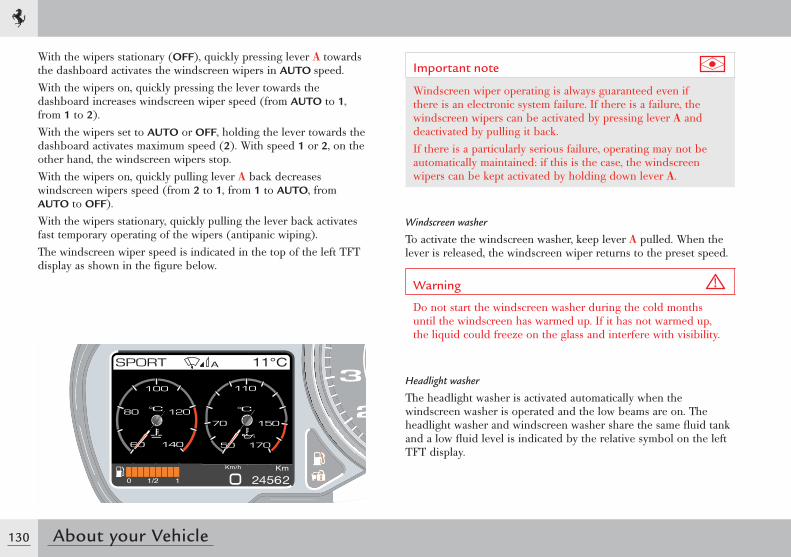
130 About your Vehicle
With the wipers stationary (OFF), quickly pressing lever A towards the dashboard activates the windscreen wipers in AUTO speed.With the wipers on, quickly pressing the lever towards the dashboard increases windscreen wiper speed (from AUTO to 1, from 1 to 2).With the wipers set to AUTO or OFF, holding the lever towards the dashboard activates maximum speed (2). With speed 1 or 2, on the other hand, the windscreen wipers stop.With the wipers on, quickly pulling lever A back decreases windscreen wipers speed (from 2 to 1, from 1 to AUTO, from AUTO to OFF).With the wipers stationary, quickly pulling the lever back activates fast temporary operating of the wipers (antipanic wiping).The windscreen wiper speed is indicated in the top of the left TFT display as shown in the fi gure below.
Important note
Windscreen wiper operating is always guaranteed even if there is an electronic system failure. If there is a failure, the windscreen wipers can be activated by pressing lever A and deactivated by pulling it back.If there is a particularly serious failure, operating may not be automatically maintained: if this is the case, the windscreen wipers can be kept activated by holding down lever A.
Windscreen washer
To activate the windscreen washer, keep lever A pulled. When the lever is released, the windscreen wiper returns to the preset speed.
Warning
Do not start the windscreen washer during the cold months until the windscreen has warmed up. If it has not warmed up, the liquid could freeze on the glass and interfere with visibility.
Headlight washer
The headlight washer is activated automatically when the windscreen washer is operated and the low beams are on. The headlight washer and windscreen washer share the same fl uid tank and a low fl uid level is indicated by the relative symbol on the left TFT display.
A
131
4
About your Vehicle
Rain sensor
The rain sensor automatically adjusts the windscreen wiper timing to the intensity of the rain. The system is activated by moving the windscreen wiper to AUTO.When operating automatically, the wiper speed ranges from a minimum intermittent setting (one wipe every 5 seconds approx.) when the windscreen is damp to fast continuous operation in heavy rain.
Important note
The rain sensor function is deactivated by turning the ignition key to position 0 and leaving the windscreen wiper in position AUTO. To reactivate the system at the next key-on, set the wipers to AUTO by quickly pressing the lever A towards the dashboard.
Warning
Before cleaning the front windscreen (for example in service stations) make sure the rain sensor is deactivated or that the key is in position 0. The rain sensor must be deactivated also when washing the vehicle by hand or in automatic car washes.In case of ice or snow on the front windscreen, do not activate the rain sensor to avoid damaging the wiper motor and/or blades.
Rain sensor failure
If there is a rain sensor failure, indicated by a special symbol on the left TFT display (see page 118) while the windscreen wiper is set to AUTO, the wipers will be set to intermittent operation with one wipe every 1 second approximately. If this is the case, we recommend that you deactivate the rain sensor and turn on the wipers, if necessary, in continuous mode.
Important note
If this occurs, contact the Ferrari Service Network as soon as possible.
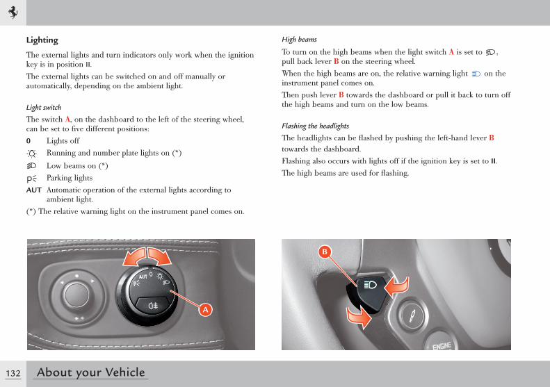
132 About your Vehicle
Lighting
The external lights and turn indicators only work when the ignition key is in position II.The external lights can be switched on and off manually or automatically, depending on the ambient light.
Light switch
The switch A, on the dashboard to the left of the steering wheel, can be set to five different positions:0 Lights off
Running and number plate lights on (*)
Low beams on (*) Parking lights
AUT Automatic operation of the external lights according to ambient light.
(*) The relative warning light on the instrument panel comes on.
A
High beams
To turn on the high beams when the light switch A is set to , pull back lever B on the steering wheel.When the high beams are on, the relative warning light on the instrument panel comes on.Then push lever B towards the dashboard or pull it back to turn off the high beams and turn on the low beams.
Flashing the headlights
The headlights can be flashed by pushing the left-hand lever B towards the dashboard.Flashing also occurs with lights off if the ignition key is set to II.The high beams are used for flashing.
B
133
4
About your Vehicle
Important note
Follow the Road Regulations of the country you are travelling in for using the high beams.
Parking lights
The parking lights work only with the ignition key in position 0 or with the key removed.
They are activated by turning the light switch A to position .When the parking lights are on, the warning light illuminates on the instrument panel .When the parking lights are on, hold down one of the two turn indicators C buttons on the steering wheel (see page 134) for more than 0.5 seconds to turn on the partial parking lights on the corresponding side; press the same turn indicator again for more than 0.5 seconds to go back to full parking lights.When the partial parking lights are on (on only one side of the vehicle), the running light warning light turns off whereas the vehicle symbol indicating which parking light is on (left or right) is displayed on the left TFT display for 10 seconds.When the light switch A is turned to AUT and the ignition key is in position II, the running lights, low beams and number plate lights turn on and off automatically according to the ambient light.
Important note
The high beams can only be activated manually by pulling back the left-hand lever B.
Important note
If the high beam control is activated, the high beams will turn on every time the lights are activated automatically. We recommend therefore that you turn them off every time the twilight sensor deactivates the external lights.
Warning
If there is fog during the day, the running lights and low beams will not be turned on automatically. The driver must always be ready to turn on the lights manually and also the rear fog lights, if necessary.
Important note
After automatic activation of the external lights, it will always be possible to turn on the rear fog lights manually. When the external lights are deactivated automatically, the rear fog lights are also turned off (if active) automatically. Therefore, if necessary, the driver will have to turn on the rear fog lights manually upon the next automatic activation.
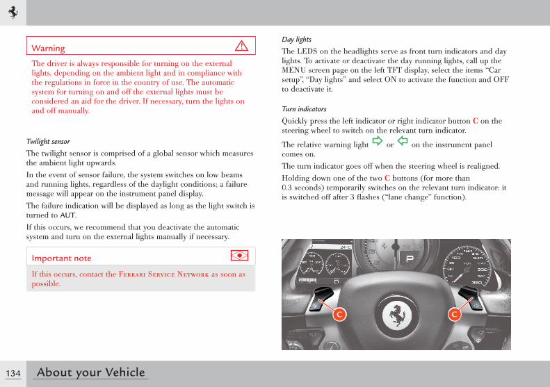
134 About your Vehicle
Warning
The driver is always responsible for turning on the external lights, depending on the ambient light and in compliance with the regulations in force in the country of use. The automatic system for turning on and off the external lights must be considered an aid for the driver. If necessary, turn the lights on and off manually.
Twilight sensor
The twilight sensor is comprised of a global sensor which measures the ambient light upwards.In the event of sensor failure, the system switches on low beams and running lights, regardless of the daylight conditions; a failure message will appear on the instrument panel display.The failure indication will be displayed as long as the light switch is turned to AUT.If this occurs, we recommend that you deactivate the automatic system and turn on the external lights manually if necessary.
Important note
If this occurs, contact the Ferrari Service Network as soon as possible.
Day lights
The LEDS on the headlights serve as front turn indicators and day lights. To activate or deactivate the day running lights, call up the MENU screen page on the left TFT display, select the items “Car setup”, “Day lights” and select ON to activate the function and OFF to deactivate it.
Turn indicators
Quickly press the left indicator or right indicator button C on the steering wheel to switch on the relevant turn indicator.
The relative warning light or on the instrument panel comes on.The turn indicator goes off when the steering wheel is realigned.Holding down one of the two C buttons (for more than 0.3 seconds) temporarily switches on the relevant turn indicator: it is switched off after 3 flashes (“lane change” function).
C C
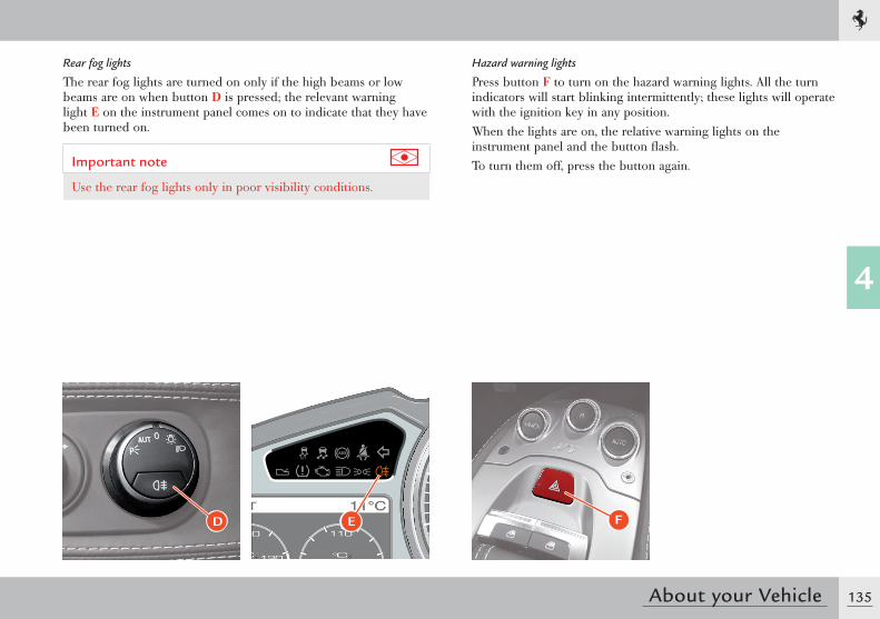
135
4
About your Vehicle
Rear fog lights
The rear fog lights are turned on only if the high beams or low beams are on when button D is pressed; the relevant warning light E on the instrument panel comes on to indicate that they have been turned on.
Important note
Use the rear fog lights only in poor visibility conditions.
Hazard warning lights
Press button F to turn on the hazard warning lights. All the turn indicators will start blinking intermittently; these lights will operate with the ignition key in any position.When the lights are on, the relative warning lights on the instrument panel and the button fl ash.To turn them off, press the button again.
D E F
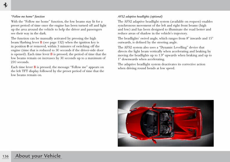
136 About your Vehicle
AFS2 adaptive headlights (optional)
The AFS2 adaptive headlight system (available on request) enables synchronous movement of the left and right front beams (high and low) and has been designed to illuminate the road better and reduce areas of shadow in the vehicle's trajectory.The headlights' swivel angle, which ranges from 8° inwards and 15° outwards, is defined by the steering angle.The AFS2 system also uses a “Dynamic Levelling” device that directs the light beam vertically when accelerating and braking by moving the headlights up to 1.9° upwards when braking and up to 1° downwards when accelerating.The adaptive headlight system deactivates its corrective action when driving round bends at low speed.
“Follow me home” function
With the “Follow me home” function, the low beams stay lit for a preset period of time once the engine has been turned off and light up the area around the vehicle to help the driver and passengers see their way in the dark.The function can be manually activated by pressing the high beam/flashing lever B (see page 132) when the ignition key is in position 0 or removed, within 3 minutes of switching off the engine (time that is reduced to 30 seconds if the driver-side door is opened). Each time lever B is pressed, the period of time that the low beams remain on increases by 30 seconds up to a maximum of 210 seconds.Each time lever B is pressed, the message “Follow me” appears on the left TFT display followed by the preset period of time that the low beams remain on.
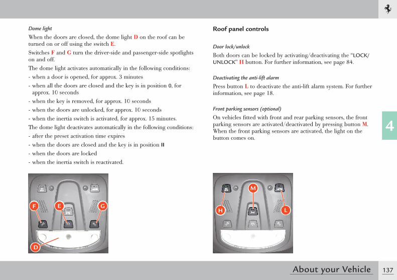
137
4
About your Vehicle
Dome light
When the doors are closed, the dome light D on the roof can be turned on or off using the switch E.Switches F and G turn the driver-side and passenger-side spotlights on and off.The dome light activates automatically in the following conditions:- when a door is opened, for approx. 3 minutes- when all the doors are closed and the key is in position 0, for
approx. 10 seconds- when the key is removed, for approx. 10 seconds- when the doors are unlocked, for approx. 10 seconds- when the inertia switch is activated, for approx. 15 minutes.The dome light deactivates automatically in the following conditions:- after the preset activation time expires- when the doors are closed and the key is in position II- when the doors are locked- when the inertia switch is reactivated.
D
F E G
Roof panel controls
Door lock/unlock
Both doors can be locked by activating/deactivating the “LOCK/UNLOCK” H button. For further information, see page 84.
Deactivating the anti-lift alarm
Press button L to deactivate the anti-lift alarm system. For further information, see page 18.
Front parking sensors (optional)
On vehicles fitted with front and rear parking sensors, the front parking sensors are activated/deactivated by pressing button M. When the front parking sensors are activated, the light on the button comes on.
M
H L
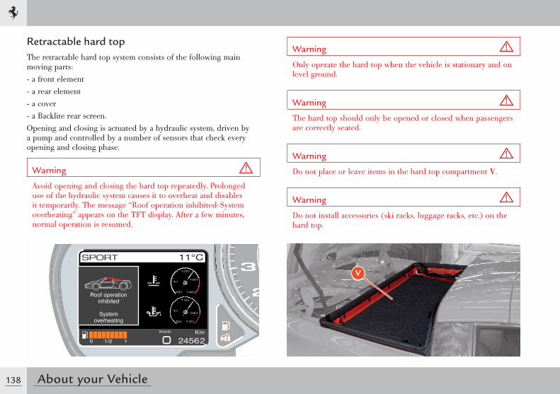
138 About your Vehicle
Retractable hard topThe retractable hard top system consists of the following main moving parts:- a front element- a rear element- a cover- a Backlite rear screen.Opening and closing is actuated by a hydraulic system, driven by a pump and controlled by a number of sensors that check every opening and closing phase.
Warning
Avoid opening and closing the hard top repeatedly. Prolonged use of the hydraulic system causes it to overheat and disables it temporarily. The message “Roof operation inhibited-System overheating” appears on the TFT display. After a few minutes, normal operation is resumed.
Warning
Only operate the hard top when the vehicle is stationary and on level ground.
Warning
The hard top should only be opened or closed when passengers are correctly seated.
Warning
Do not place or leave items in the hard top compartment V.
Warning
Do not install accessories (ski racks, luggage racks, etc.) on the hard top.
Roof operationinhibited
Systemoverheating
V
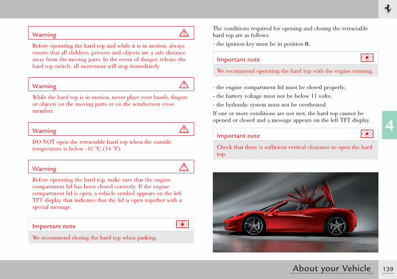
139
4
About your Vehicle
Warning
Before operating the hard top and while it is in motion, always ensure that all children, persons and objects are a safe distance away from the moving parts. In the event of danger, release the hard top switch: all movement will stop immediately.
Warning
While the hard top is in motion, never place your hands, fingers or objects on the moving parts or on the windscreen cross member.
Warning
DO NOT open the retractable hard top when the outside temperature is below -10 °C (14 °F).
Warning
Before operating the hard top, make sure that the engine compartment lid has been closed correctly. If the engine compartment lid is open, a vehicle symbol appears on the left TFT display that indicates that the lid is open together with a special message.
Important note
We recommend closing the hard top when parking.
The conditions required for opening and closing the retractable hard top are as follows:- the ignition key must be in position II;
Important note
We recommend operating the hard top with the engine running.
- the engine compartment lid must be closed properly;- the battery voltage must not be below 11 volts;- the hydraulic system must not be overheated.If one or more conditions are not met, the hard top cannot be opened or closed and a message appears on the left TFT display.
Important note
Check that there is sufficient vertical clearance to open the hard top.
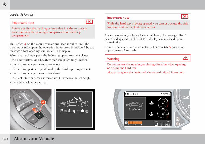
140 About your Vehicle
Opening the hard top
Important note
Before opening the hard top, ensure that it is dry to prevent water entering the passenger compartment or hard top compartment.
Pull switch A on the centre console and keep it pulled until the hard top is fully open: the operation in progress is indicated by the message “Roof opening” on the left TFT display.When the hard top opens, the following operations take place:- the side windows and BackLite rear screen are fully lowered- the hard top compartment cover opens- the hard top parts are positioned in the hard top compartment- the hard top compartment cover closes- the BackLite rear screen is raised until it reaches the set height- the side windows are raised.
Important note
While the hard top is being opened, you cannot operate the side windows and the BackLite rear screen.
Once the opening cycle has been completed, the message “Roof open” is displayed on the left TFT display accompanied by an acoustic signal.To raise the side windows completely, keep switch A pulled for approximately 2 seconds.
Warning
Do not reverse the opening or closing direction when opening or closing the hard top.Always complete the cycle until the acoustic signal is emitted.
A
Roof openRoof opening
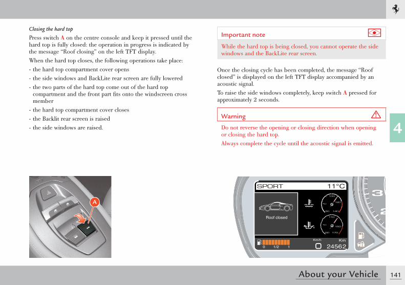
141
4
About your Vehicle
Closing the hard top
Press switch A on the centre console and keep it pressed until the hard top is fully closed: the operation in progress is indicated by the message “Roof closing” on the left TFT display.When the hard top closes, the following operations take place:- the hard top compartment cover opens- the side windows and BackLite rear screen are fully lowered- the two parts of the hard top come out of the hard top
compartment and the front part fi ts onto the windscreen cross member
- the hard top compartment cover closes- the Backlit rear screen is raised- the side windows are raised.
Roof closed
A
Important note
While the hard top is being closed, you cannot operate the side windows and the BackLite rear screen.
Once the closing cycle has been completed, the message “Roof closed” is displayed on the left TFT display accompanied by an acoustic signal.To raise the side windows completely, keep switch A pressed for approximately 2 seconds.
Warning
Do not reverse the opening or closing direction when opening or closing the hard top.Always complete the cycle until the acoustic signal is emitted.
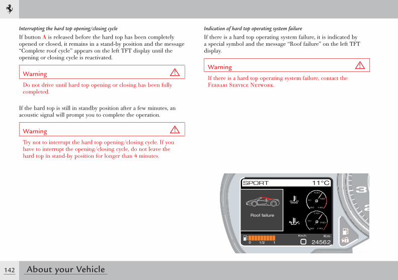
142 About your Vehicle
Interrupting the hard top opening/closing cycle
If button A is released before the hard top has been completely opened or closed, it remains in a stand-by position and the message “Complete roof cycle” appears on the left TFT display until the opening or closing cycle is reactivated.
Warning
Do not drive until hard top opening or closing has been fully completed.
If the hard top is still in standby position after a few minutes, an acoustic signal will prompt you to complete the operation.
Warning
Try not to interrupt the hard top opening/closing cycle. If you have to interrupt the opening/closing cycle, do not leave the hard top in stand-by position for longer than 4 minutes.
Indication of hard top operating system failure
If there is a hard top operating system failure, it is indicated by a special symbol and the message “Roof failure” on the left TFT display.
Warning
If there is a hard top operating system failure, contact the Ferrari Service Network.
Roof failure
143
4
About your Vehicle
Driving the vehicle
Running-in
The latest manufacturing techniques have allowed us to achieve high precision and accuracy levels in the construction and assembly of components. Nonetheless, the vehicle movable parts undergo a settling process, basically during the first hours of operation.
Engine and transmission
Avoid exceeding 5,000 RPM for the first 1,000 km (620 mi).After starting, do not exceed 4,000 RPM until the engine has warmed up (oil temperature: 65-70 °C / 149-158 °F).Do not let the engine run at a constantly high speed for a prolonged time.
Warning
BEFORE YOU DRIVECheck that the seat belts are fastenedCheck that the doors are closedCheck that the seat is properly adjustedCheck the rear-view mirror adjustment (central and sides).
Before a trip
Preliminary checks
Check the following at regular intervals and always before long trips:- tyre pressure and condition- levels of fluids and lubricants- condition of the windscreen wiper blades- proper functioning of the warning lights and external lights.
Important note
In any case, it is advisable to perform these checks at least every 1000 km (620 mi) and always comply with the maintenance schedule.
It is also advisable to:
- clean the glass covers of the external lights and all the glass surfaces
- properly adjust the mirrors, steering wheel, seats and seat belts.
Refilling
Warning
Use unleaded fuel only!Using leaded fuel would permanently damage the catalytic converters.
For specifications and quantities of lubricants and fluids, refer to the “Refilling” table on page 31.
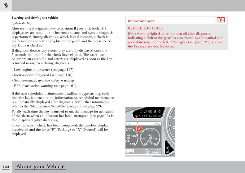
144 About your Vehicle
Starting and driving the vehicle
System start-up
After turning the ignition key to position II (key-on), both TFT displays are activated on the instrument panel and system diagnosis is performed. During diagnosis, which lasts 5 seconds, a check is performed on the warning lights on the panel and the presence of any faults is checked.If diagnosis detects any errors, they are only displayed once the 5 seconds required for the check have elapsed. The cases listed below are an exception and errors are displayed as soon as the key is turned to on, even during diagnosis:
- Low engine oil pressure (see page 117)- Inertia switch triggered (see page 116)- Semi-automatic gearbox safety warnings- EPB deactivation warning (see page 161).
If the next scheduled maintenance deadline is approaching, each time the key is turned to on, information on scheduled maintenance is automatically displayed after diagnosis. For further information, refer to the “Maintenance Schedule” paragraph on page 226.Finally, each time the key is turned to on, the message for activation of the alarm when an intrusion has been attempted (see page 19) is also displayed (after diagnosis).Once the system check has been completed, the gearbox display is activated and the letter “P” (Parking) or “N” (Neutral) will be displayed.
Important note
BEFORE YOU DRIVEIf the warning light A does not turn off after diagnosis, indicating a fault in the gearbox also shown by the symbol and special message on the left TFT display (see page 121), contact the Ferrari Service Network.
A
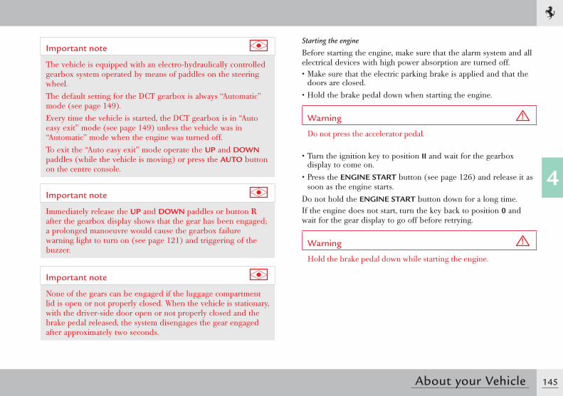
145
4
About your Vehicle
Important note
The vehicle is equipped with an electro-hydraulically controlled gearbox system operated by means of paddles on the steering wheel.The default setting for the DCT gearbox is always “Automatic” mode (see page 149).Every time the vehicle is started, the DCT gearbox is in “Auto easy exit” mode (see page 149) unless the vehicle was in “Automatic” mode when the engine was turned off.To exit the “Auto easy exit” mode operate the UP and DOWN paddles (while the vehicle is moving) or press the AUTO button on the centre console.
Important note
Immediately release the UP and DOWN paddles or button R after the gearbox display shows that the gear has been engaged; a prolonged manoeuvre would cause the gearbox failure warning light to turn on (see page 121) and triggering of the buzzer.
Important note
None of the gears can be engaged if the luggage compartment lid is open or not properly closed. When the vehicle is stationary, with the driver-side door open or not properly closed and the brake pedal released, the system disengages the gear engaged after approximately two seconds.
Starting the engine
Before starting the engine, make sure that the alarm system and all electrical devices with high power absorption are turned off.• Make sure that the electric parking brake is applied and that the
doors are closed.• Hold the brake pedal down when starting the engine.
Warning
Do not press the accelerator pedal.
• Turn the ignition key to position II and wait for the gearbox display to come on.
• Press the ENGINE START button (see page 126) and release it as soon as the engine starts.
Do not hold the ENGINE START button down for a long time.If the engine does not start, turn the key back to position 0 and wait for the gear display to go off before retrying.
Warning
Hold the brake pedal down while starting the engine.
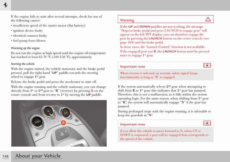
146 About your Vehicle
If the engine fails to start after several attempts, check for one of the following causes:• insufficient speed of the starter motor (flat battery)• ignition device faulty• electrical contacts faulty• fuel pump fuses blown.
Warming up the engine
Do not run the engine at high speed until the engine oil temperature has reached at least 65-70 °C (149-158 °F), approximately.
Starting the vehicle
With the engine started, the vehicle stationary and the brake pedal pressed, pull the right-hand “UP” paddle towards the steering wheel to engage 1st gear.Release the brake pedal and press the accelerator to start off.With the engine running and the vehicle stationary, you can change directly from 1st or 2nd gear to “R” (reverse) by pressing R on the centre console and from reverse to 1st by moving the UP paddle.
Warning
If the UP and DOWN paddles are not working, the message “Depress brake pedal and press LAUNCH to engage gear” will appear on the left TFT display; you can therefore engage the gear by pressing the LAUNCH button on the centre console (see page 164) and the brake pedal.In these cases, the “Launch Control” function is not available.If the engaged gear was R, the LAUNCH button must be pressed twice to engage 1st gear.
Important note
When reverse is selected, an acoustic safety signal beeps intermittently as long as “R” is engaged.
If the system automatically selects 2nd gear when attempting to shift from R to 1st gear, this indicates that 1st gear has jammed. Therefore, this is not a malfunction, as it falls within the system operating logic. For the same reason, when shifting from 1st gear to “R”, the system will automatically engage “N” if the gear has jammed.During prolonged stops with the engine running, it is advisable to keep the gearshift in “N”.
Important note
If you allow the vehicle to move forward in N, when UP or DOWN is requested, a gear will be engaged that corresponds to the speed of the vehicle.
R
147
4
About your Vehicle
UP-shifting
Use the right-hand UP paddle without releasing the accelerator pedal.An UP-shift request is not accepted when engagement of the requested gear forces the engine to underrev or if an UP-shift is already in progress because of engine overrevving.In any event, it is advisable to: • Shift gears without releasing the accelerator pedal if pressed. • Wait until gearshifting has been completed before requesting the
next shift, avoiding a rapid sequence of multiple requests.
UP-shifting due to overrevving
The system “automatically” engages a higher gear if the accelerator pedal is pressed and the engine approaches the “runaway speed rate” (overrevving).
Important note
This will not occur when the system is in “RACE”, “CT OFF” and “ESC OFF” driving modes.
DOWN-shifting
Use the left-hand DOWN paddle without releasing the accelerator pedal.A DOWN-shift request is not accepted if engagement of the requested gear forces the engine beyond a certain RPM, depending on the gear requested, or if a DOWN-shift is already in progress because of engine underrevving.In any event, it is advisable to:• Shift gears without releasing the accelerator pedal if pressed. • If DOWN-shifting is requested to start overtaking which requires
quick acceleration, press the accelerator pedal just before using the paddle.
• Wait until gearshifting has been completed before requesting the next shift, avoiding a rapid sequence of multiple requests.
DOWN-shifting due to underrevving
• The system shifts down “automatically” if the engine goes below a minimum number of revs (1250 RPM).
• The DOWN-shift request from the paddle is ignored if gearshifting is already in progress due to engine underrevving.
Sequential downshifting
During deceleration, with the brake pedal pressed and the ABS system disabled, sequential downshifting can be performed by holding the left-hand “DOWN” paddle down.The sequential gearshifting request is accepted until the second gear is engaged.This system is only activated when the “Manettino” is set to SPORT, RACE, CT OFF or ESC OFF.
148 About your Vehicle
“N” (Neutral) request
With the engine running, pull both UP and DOWN paddles towards the steering wheel at the same time without pressing the brake pedal to request neutral “N”.If necessary, “N” can be requested at any speed. Subsequently, if an “UP” or “DOWN” shift is requested, the system will engage the gear most suited to the speed of the vehicle.
Stopping the vehicle
When the vehicle stops, the system automatically engages 1st gear unless Neutral has already been requested.When the vehicle is stationary and the engine is running, hold the brake pedal down until ready to move off again.
Switching off the engine
The engine can be switched off with the gearbox either in “N” or with a gear engaged.After turning the ignition key from position II to position 0, the gearbox display will remain on for a few more seconds to display the engaged gear. If the gearbox is in “N” a buzzer will sound. Before switching off, the letter “P” is displayed on the gearbox display to inform the driver that the Park Lock has been activated.
Warning
Never leave the vehicle with the gearbox in “N”. Always make sure that the letter “P” (Parking) appears on the gearbox display.
Warning
Never leave the vehicle with the engine running.
Important note
If the vehicle is not in Parking mode (the letter “P” must be displayed on the gearbox display), the key cannot be removed.
For information on the Park Lock, see page 163.
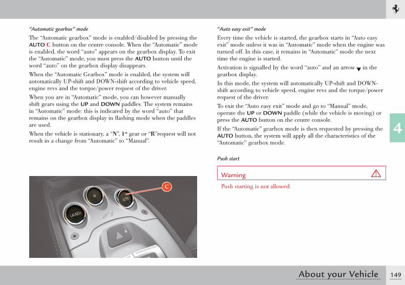
149
4
About your Vehicle
“Automatic gearbox” mode
The “Automatic gearbox” mode is enabled/disabled by pressing the AUTO C button on the centre console. When the “Automatic” mode is enabled, the word “auto” appears on the gearbox display. To exit the “Automatic” mode, you must press the AUTO button until the word “auto” on the gearbox display disappears.When the “Automatic Gearbox” mode is enabled, the system will automatically UP-shift and DOWN-shift according to vehicle speed, engine revs and the torque/power request of the driver.When you are in “Automatic” mode, you can however manually shift gears using the UP and DOWN paddles. The system remains in “Automatic” mode: this is indicated by the word “auto” that remains on the gearbox display in flashing mode when the paddles are used.When the vehicle is stationary, a “N”, 1st gear or “R”request will not result in a change from “Automatic” to “Manual”.
“Auto easy exit” mode
Every time the vehicle is started, the gearbox starts in “Auto easy exit” mode unless it was in “Automatic” mode when the engine was turned off. In this case, it remains in “Automatic” mode the next time the engine is started.Activation is signalled by the word “auto” and an arrow in the gearbox display.In this mode, the system will automatically UP-shift and DOWN-shift according to vehicle speed, engine revs and the torque/power request of the driver.To exit the “Auto easy exit” mode and go to “Manual” mode, operate the UP or DOWN paddle (while the vehicle is moving) or press the AUTO button on the centre console.If the “Automatic” gearbox mode is then requested by pressing the AUTO button, the system will apply all the characteristics of the “Automatic” gearbox mode.
Push start
Warning
Push starting is not allowed.C
150 About your Vehicle
Safe driving
For safe driving, it is essential that the driver be aware of the best driving techniques suited to various circumstances. Always try to prevent dangerous situations by driving with caution.Before you drive
- Adjust the position of the seat, steering wheel and rear-view mirrors, in order to obtain the best driving position.
- Adjust the backrest so that your chest is upright and your head is as close to the headrest as possible.
- Ensure that nothing (e.g. mat covers, etc.) is blocking the pedals.- Check that the lights and headlights are working properly.- Ensure that any child restraint systems (e.g. child seats, cradles
etc.) are properly fixed on the passenger seat.- Your reflexes are quicker if you eat lightly before driving: avoid
heavy meals before a trip.- Do not drink alcoholic drinks before and during the journey.At regular intervals, check the following:- Tyre pressure and condition.- Engine oil level.- Engine coolant level and system condition.- Brake fluid level.- Steering fluid level.- Windscreen washer fluid level.
While travelling
- Caution is the number one rule for safe driving, which also means you should take other people’s behaviour into consideration.
- Follow the Road Regulations in force in the country you are driving in and always respect the speed limit.
- Always make sure that the driver and passengers have their seat belts fastened and that all children are travelling in suitable child seats.
- Good personal physical conditions ensure you can drive long distances safely.
Warning
Driving under the influence of drugs, some medicines and alcohol is dangerous to yourself and others as well as contravening road regulations and legal norms.Travelling without your seat belt fastened increases the risk of serious injury and death in the event of a collision. Always fasten seat belts and use child seats, if present.Do not travel with objects lying on the floor, especially in front of the driver’s seat: in the event of braking, these could slide under the pedals, making it impossible to brake or accelerate.Additionally, ensure that any loose floor mats sit correctly.Water, ice and salt spread on icy roads may deposit on the brake discs and reduce the efficiency of the initial braking.
151
4
About your Vehicle
- Make regular stops to loosen up your limbs and refresh yourself, and avoid driving for hours on end.
- Keep a constant air circulation in the passenger compartment.- Never coast downhill with the engine off: in these conditions
the engine brake, servo brake and power steering are inefficient, braking requires greater pressure on the pedal and steering will be harder.
Driving at night
When you are travelling at night, follow these fundamental rules:- Reduce speed, particularly on dark roads.- Driving conditions are more demanding at night, so take
particular care.- If you start feeling tired or sleepy, stop immediately: to continue
driving would be a risk for yourself and for others. Continue only after you have had a rest.
- At night, it is difficult to judge the speed of vehicles in front of you as you can only see their taillights: keep at a greater safety distance than you would during the day.
- Use the high beams only outside of urban areas and when you are sure that they will not disturb other drivers.
- Turn off the high beams when you see oncoming vehicles and use the low beams.
- Keep the lights and headlights clean.- Watch out for animals crossing the road when travelling outside
urban areas.
Driving in the rain
Rain and wet roads can cause hazardous situations.All manoeuvres are more difficult on a wet road since tyres have significantly less grip on the road. This means that the braking distances increase considerably and road-holding decreases.Below is some advice for driving in the rain:- Keep a greater safety distance between yourself and the other
vehicles and reduce your speed.- When it is raining very hard, visibility is also reduced. In these
cases, to make yourself more visible to others, turn on the low beams even during the day.
- Drive through puddles at low speed to avoid losing control of the vehicle (“aquaplaning”): if this occurs, grip the steering wheel firmly.
Warning
If the road is wet, reduce your speed to avoid “aquaplaning” (when the tyre no longer touches the road surface because the side channels of the tyre tread are not capable of removing all the channelled water due to their particular shape or insufficient depth and a layer of water is placed between the road surface and the tyre. The fluid pressure generated is so high that it supports the vehicle's weight making it virtually impossible for the driver to control the vehicle).
152 About your Vehicle
- Use the ventilation system to demist the windscreen (see page 184) and avoid visibility problems.
- Periodically check the condition of the windscreen wiper blades.
Driving in fog
Whenever possible, avoid travelling if there is thick fog. If you have to drive in misty conditions, or if there is thick fog or fog banks, follow these rules:- Keep a moderate speed.- Turn on the low beams, also during the day, and use the rear fog
light. Avoid using the high beams.
Warning
On stretches where visibility is good, turn off the rear fog light, it may be annoying for the occupants of the vehicles behind you.
- Remember that fog makes the road damp and therefore all manoeuvres are more difficult and braking distances are longer.
- Keep a safe distance from the vehicle in front of you.- As far as possible, avoid suddenly changing speed and direction.- As far as possible, avoid overtaking.- In the event of an emergency stop, (e.g. failures, inability to
proceed due to poor visibility conditions, etc.) try to free the main driving lane. Then turn on the hazard warning lights and, if possible, the low beams. On approaching another vehicle, sound the horn rhythmically.
Driving on mountain roads
Below is some advice for driving on steep mountain roads:- To prevent the brakes from overheating when driving downhill,
use the engine to brake by engaging a lower gear.- Never coast downhill or drive downhill with the engine off or
in neutral, nor with the ignition key removed from the steering column.
- Drive at a moderate speeds and do not “cut” corners.- Remember that overtaking uphill is slower and requires a longer
free stretch of road. If you are overtaken when driving uphill, ensure that the other vehicle can pass easily.
Driving on snowy or icy roads
Below is some advice for driving in these conditions:- Keep a very moderate speed.- Keep a safe distance from the vehicles in front of you.- Fit snow tyres approved for the vehicle.- Given the poor grip, use the engine brake as much as possible
and avoid sudden braking.- Avoid sudden acceleration and sharp changes in direction.- During the winter season, even apparently dry roads can have icy
sections.Therefore, be careful when driving along stretches of road in the shade as there may be icy patches.
153
4
About your Vehicle
Driving with the “ABS” braking system
The ABS system assists the driver as follows:- It prevents the wheels from locking and skidding during
emergency braking, particularly in low-grip conditions.- It allows braking and changing direction at the same time. This
feature is affected by the physical limits and lateral grip of the tyres.
- When the ABS is activated, you will feel a slight pulsing of the brake pedal during emergency braking or in low-grip conditions. DO NOT release the pedal but continue to push it to give continuity to the braking action.
- The ABS prevents the wheels from locking, but it does not increase the physical limits of grip between the tyres and the road: keep a safe distance from the vehicles ahead and reduce speed before curves.
Power steering system
The power steering system uses the power produced by the engine to help the driver steer more precisely while exerting less force on the steering wheel.
Important note
Remember that power steering does not work when the engine is switched off and more force is therefore needed when steering.
Warning
Do not keep the steering wheel fully turned (locked position) to the right or the left for more than 15 seconds when the engine is running. This may damage the power steering system.
Important note
If the power steering system is not working properly, as indicated by a symbol which appears on the left TFT display (see page 118), contact the Ferrari Service Network.
154 About your Vehicle
Suspension damping control
This vehicle uses latest generation MagneRide™ magnetorheological suspension, a system developed by Delphi and perfected by Ferrari for continuous automatic damping control.By processing data received from the vehicle dynamics sensors and sensors that detect bodyshell movements, the ECU interprets the driving conditions and the road surface and immediately adjusts suspension response by varying the control current of each shock absorber.These sensors allow the ECU to calculate the vehicle speed, vertical and lateral acceleration, steering angle and instantaneous pressure in the braking system, and hence to control suspension damping.This system not only ensures an optimal compromise between racing-style performance (handling) and comfort, but is capable of emphasising either aspect by using the different adjustments available controlled by the “Manettino” driving mode control switch. Three different setting levels are available on this vehicle.
Level 1 (COMFORT)
Slightly more flexible setting, optimised to better absorb road unevenness and provide a better grip on wet road surfaces (Manettino set to WET).
Level 2 (SPORT)
Slightly more rigid adjustment optimised for sports-style driving and for high speed (with medium-high grip), without significantly affecting comfort (Manettino set to SPORT).
Level 3 (RACE)
Even more rigid setting optimised for use on the race track (Manettino set to RACE, CT OFF, ESC OFF).
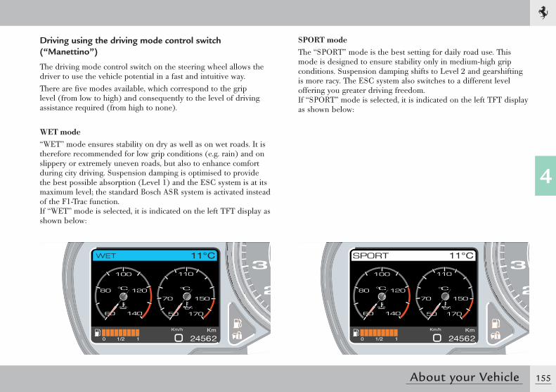
155
4
About your Vehicle
Driving using the driving mode control switch (“ Manettino”)
The driving mode control switch on the steering wheel allows the driver to use the vehicle potential in a fast and intuitive way.There are fi ve modes available, which correspond to the grip level (from low to high) and consequently to the level of driving assistance required (from high to none).
WET mode“WET” mode ensures stability on dry as well as on wet roads. It is therefore recommended for low grip conditions (e.g. rain) and on slippery or extremely uneven roads, but also to enhance comfort during city driving. Suspension damping is optimised to provide the best possible absorption (Level 1) and the ESC system is at its maximum level; the standard Bosch ASR system is activated instead of the F1-Trac function.If “WET” mode is selected, it is indicated on the left TFT display as shown below:
SPORT modeThe “SPORT” mode is the best setting for daily road use. This mode is designed to ensure stability only in medium-high grip conditions. Suspension damping shifts to Level 2 and gearshifting is more racy. The ESC system also switches to a different level offering you greater driving freedom.If “SPORT” mode is selected, it is indicated on the left TFT display as shown below:
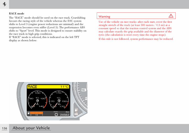
156 About your Vehicle
RACE modeThe “RACE” mode should be used on the race track. Gearshifting favours the racing style of the vehicle whereas the ESC system shifts to Level 3 (engine power reductions are minimal) and the suspension becomes even stiffer (Level 3). The performance ABS shifts to “Sport” level. This mode is designed to ensure stability on the race track in high grip conditions.If “RACE” mode is selected, this is indicated on the left TFT display as shown below:
Warning
Use of the vehicle on race tracks: after each start, cover the fi rst straight stretch of the track (at least 500 meters / 0.3 mi) at a constant speed so that the traction control system and the ABS may calculate exactly the grip available and the diameter of the tyres (the calculation is reset every time the engine stops).If this rule is not followed, system performance may be reduced.
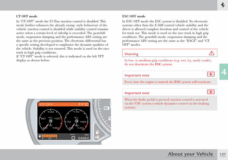
157
4
About your Vehicle
ESC OFF modeIn ESC OFF mode the ESC system is disabled. No electronic systems other than the E-Diff control vehicle stability and the driver is allowed complete freedom and control of the vehicle for track use. This mode is used on the race track in high grip conditions. The gearshift mode, suspension damping and the performance ABS setting are the same as the “RACE” and “CT OFF” modes.
Warning
In low- to medium-grip conditions (e.g. wet, icy, sandy roads), do not deactivate the ESC system.
Important note
Every time the engine is started, the ESC system will reactivate.
Important note
When the brake pedal is pressed, traction control is activated via the VDC system (vehicle dynamics control via the braking system).
CT OFF modeIn “CT OFF” mode the F1-Trac traction control is disabled. This mode further enhances the already racing -style behaviour of the vehicle: traction control is disabled while stability control remains active when a certain level of sideslip is exceeded. The gearshift mode, suspension damping and the performance ABS setting are the same as the previous position. The electronic differential has a specifi c setting developed to emphasise the dynamic qualities of the vehicle. Stability is not ensured. This mode is used on the race track in high grip conditions.If “CT OFF” mode is selected, this is indicated on the left TFT display as shown below:
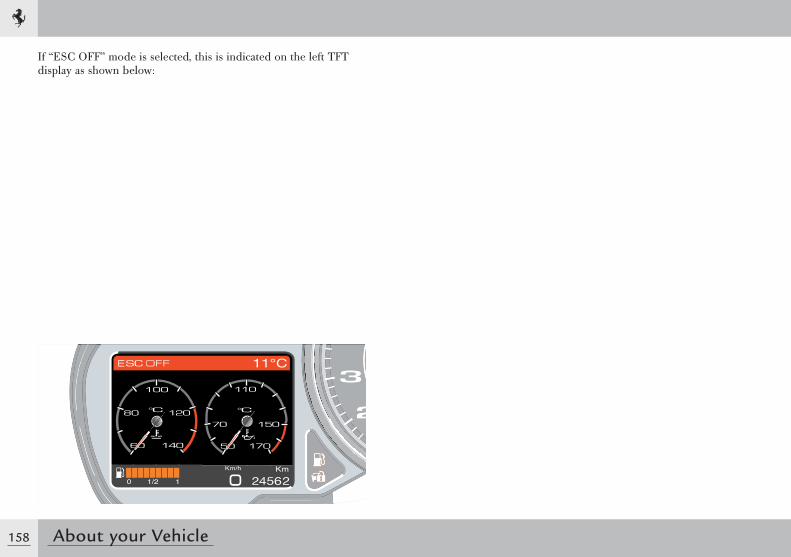
158 About your Vehicle
If “ESC OFF” mode is selected, this is indicated on the left TFT display as shown below:
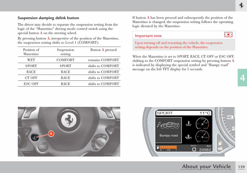
159
4
About your Vehicle
Suspension damping delink button
The driver may decide to separate the suspension setting from the logic of the “Manettino” driving mode control switch using the special button A on the steering wheel.By pressing button A, irrespective of the position of the Manettino, the suspension setting shifts to Level 1 (COMFORT).
Position of Manettino
Suspension setting
Button A pressed
WET COMFORT remains COMFORT
SPORT SPORT shifts to COMFORT
RACE RACE shifts to COMFORT
CT OFF RACE shifts to COMFORT
ESC OFF RACE shifts to COMFORT
A
If button A has been pressed and subsequently the position of the Manettino is changed, the suspension setting follows the operating logic dictated by the Manettino.
Important note
Upon turning off and restarting the vehicle, the suspension setting depends on the position of the Manettino.
When the Manettino is set to SPORT, RACE, CT OFF or ESC OFF, shifting to the COMFORT suspension setting by pressing button A is indicated by displaying the special symbol and “Bumpy road” message on the left TFT display for 5 seconds.
Bumpy road
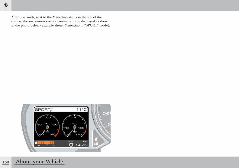
160 About your Vehicle
After 5 seconds, next to the Manettino status in the top of the display, the suspension symbol continues to be displayed as shown in the photo below (example shows Manettino in “SPORT” mode).
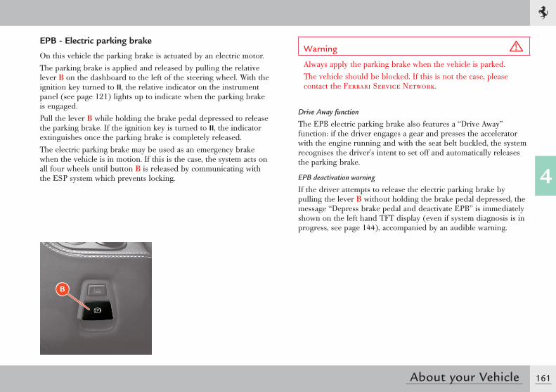
161
4
About your Vehicle
EPB - Electric parking brake
On this vehicle the parking brake is actuated by an electric motor.The parking brake is applied and released by pulling the relative lever B on the dashboard to the left of the steering wheel. With the ignition key turned to II, the relative indicator on the instrument panel (see page 121) lights up to indicate when the parking brake is engaged.Pull the lever B while holding the brake pedal depressed to release the parking brake. If the ignition key is turned to II, the indicator extinguishes once the parking brake is completely released.The electric parking brake may be used as an emergency brake when the vehicle is in motion. If this is the case, the system acts on all four wheels until button B is released by communicating with the ESP system which prevents locking.
B
Warning
Always apply the parking brake when the vehicle is parked.The vehicle should be blocked. If this is not the case, please contact the Ferrari Service Network.
Drive Away function
The EPB electric parking brake also features a “Drive Away” function: if the driver engages a gear and presses the accelerator with the engine running and with the seat belt buckled, the system recognises the driver's intent to set off and automatically releases the parking brake.
EPB deactivation warning
If the driver attempts to release the electric parking brake by pulling the lever B without holding the brake pedal depressed, the message “Depress brake pedal and deactivate EPB” is immediately shown on the left hand TFT display (even if system diagnosis is in progress, see page 144), accompanied by an audible warning.
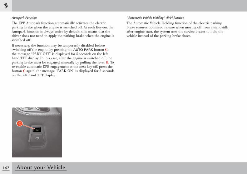
162 About your Vehicle
C
Autopark Function
The EPB Autopark function automatically activates the electric parking brake when the engine is switched off. At each Key-on, the Autopark function is always active by default: this means that the driver does not need to apply the parking brake when the engine is switched off.If necessary, the function may be temporarily disabled before switching off the engine by pressing the AUTO PARK button C: the message “PARK OFF” is displayed for 5 seconds on the left hand TFT display. In this case, after the engine is switched off, the parking brake must be engaged manually by pulling the lever B. To re-enable automatic EPB engagement at the next key-off, press the button C again; the message “PARK ON” is displayed for 5 seconds on the left hand TFT display.
“Automatic Vehicle Holding” AVH function
The Automatic Vehicle Holding function of the electric parking brake ensures optimised release when moving off from a standstill: after engine start, the system uses the service brakes to hold the vehicle instead of the parking brake shoes.
163
4
About your Vehicle
Park Lock
The Park Lock is a locking device built into the gearbox.This device is used to prevent the vehicle from moving when the multi-disc clutches are open, i.e., with the engine off and/or without the hydraulic pressure required for gearbox operating.The device operates automatically every time the key is turned to off: if a gear is engaged when the key is turned to off, the Park Lock is immediately activated. If the gearbox is in “N” (neutral), the Park Lock starts operating after a minimum preset time (needed for the Carwash procedure, see next paragraph). To inform the driver that the Park Lock has been engaged, the letter “P” is displayed on the gearbox display.The Park Lock is deactivated when the engine is running, the first gear or “R” is requested (with the brake pedal pressed) and the luggage compartment lid has been closed correctly.
Carwash procedure
The Park lock device can be electrically disabled on a temporary basis when the engine is switched off by performing the Carwash procedure.This procedure is necessary when the vehicle has to be moved with the engine off and when washing the vehicle.
Warning
When the Park Lock device is electronically deactivated (Carwash procedure), the vehicle may move. The vehicle is only kept stationary by the parking brake which must be applied.
To perform the Carwash procedure, do the following:- with the engine running, select the first gear;- select neutral “N”;- switch off the engine;- turn the key to position II (key-on) within 3 seconds of switching
off.
The message “Carwash mode activation” will appear on the left TFT display.
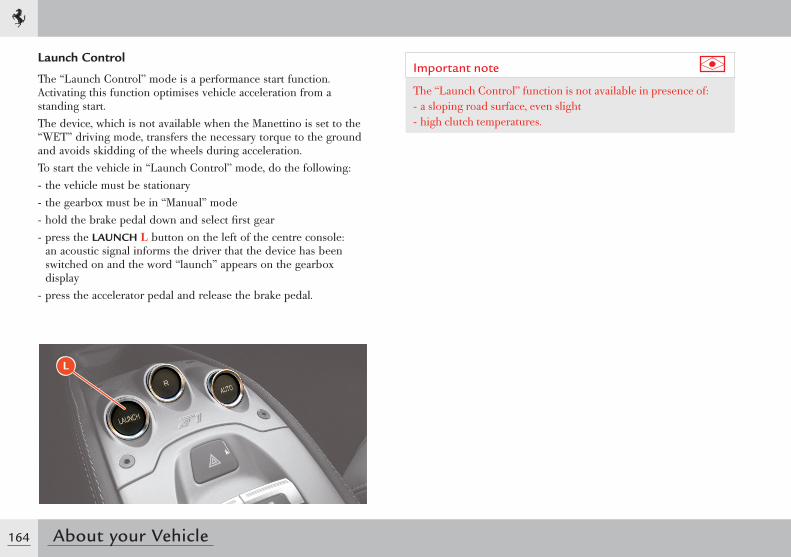
164 About your Vehicle
Launch Control
The “Launch Control” mode is a performance start function. Activating this function optimises vehicle acceleration from a standing start.The device, which is not available when the Manettino is set to the “WET” driving mode, transfers the necessary torque to the ground and avoids skidding of the wheels during acceleration.To start the vehicle in “Launch Control” mode, do the following:- the vehicle must be stationary- the gearbox must be in “Manual” mode- hold the brake pedal down and select first gear- press the LAUNCH L button on the left of the centre console:
an acoustic signal informs the driver that the device has been switched on and the word “launch” appears on the gearbox display
- press the accelerator pedal and release the brake pedal.
L
Important note
The “Launch Control” function is not available in presence of:- a sloping road surface, even slight- high clutch temperatures.
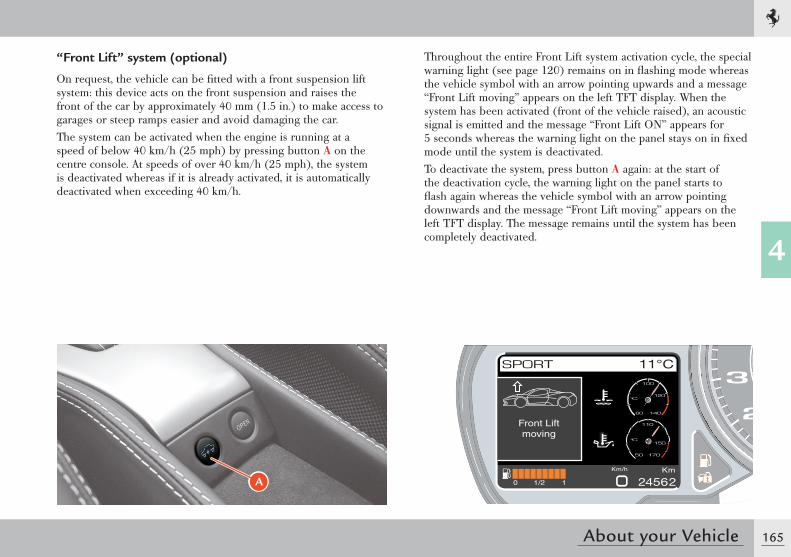
165
4
About your Vehicle
“ Front Lift” system (optional)
On request, the vehicle can be fi tted with a front suspension lift system: this device acts on the front suspension and raises the front of the car by approximately 40 mm (1.5 in.) to make access to garages or steep ramps easier and avoid damaging the car.The system can be activated when the engine is running at a speed of below 40 km/h (25 mph) by pressing button A on the centre console. At speeds of over 40 km/h (25 mph), the system is deactivated whereas if it is already activated, it is automatically deactivated when exceeding 40 km/h.
Front Liftmoving
A
Throughout the entire Front Lift system activation cycle, the special warning light (see page 120) remains on in fl ashing mode whereas the vehicle symbol with an arrow pointing upwards and a message “Front Lift moving” appears on the left TFT display. When the system has been activated (front of the vehicle raised), an acoustic signal is emitted and the message “Front Lift ON” appears for 5 seconds whereas the warning light on the panel stays on in fi xed mode until the system is deactivated.To deactivate the system, press button A again: at the start of the deactivation cycle, the warning light on the panel starts to fl ash again whereas the vehicle symbol with an arrow pointing downwards and the message “Front Lift moving” appears on the left TFT display. The message remains until the system has been completely deactivated.
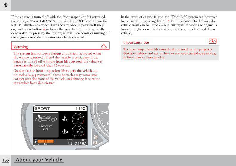
166 About your Vehicle
Front LiftON
If the engine is turned off with the front suspension lift activated, the message “Front Lift ON. Set Front Lift to OFF” appears on the left TFT display at key-off. Turn the key back to position II (key-on) and press button A to lower the vehicle. If it is not manually deactivated by pressing the button, within 15 seconds of turning off the engine, the system is automatically deactivated.
Warning
The system has not been designed to remain activated when the engine is turned off and the vehicle is stationary. If the engine is turned off with the front lift activated, the vehicle is automatically lowered after 15 seconds.Do not use the front suspension lift to park the vehicle on obstacles (e.g. pavements); these obstacles may come into contact with the front of the vehicle and damage it once the system has been deactivated.
In the event of engine failure, the “Front Lift” system can however be activated by pressing button A for 10 seconds. In this way, the vehicle front can be lifted even in emergencies when the engine is turned off (for example, to load it onto the ramp of a breakdown vehicle).
Important note
The front suspension lift should only be used for the purposes described above and not to drive over speed control systems (e.g. traffic calmers) more quickly.
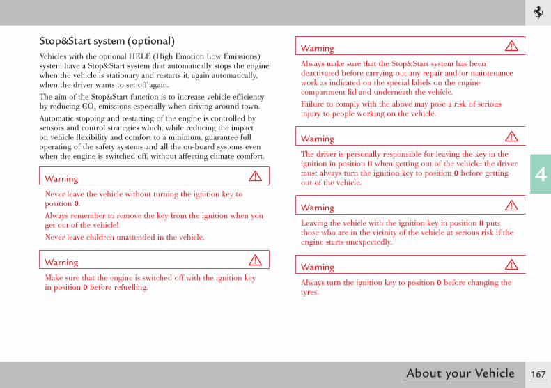
167
4
About your Vehicle
Stop&Start system (optional)Vehicles with the optional HELE (High Emotion Low Emissions) system have a Stop&Start system that automatically stops the engine when the vehicle is stationary and restarts it, again automatically, when the driver wants to set off again.The aim of the Stop&Start function is to increase vehicle efficiency by reducing CO2 emissions especially when driving around town.Automatic stopping and restarting of the engine is controlled by sensors and control strategies which, while reducing the impact on vehicle flexibility and comfort to a minimum, guarantee full operating of the safety systems and all the on-board systems even when the engine is switched off, without affecting climate comfort.
Warning
Never leave the vehicle without turning the ignition key to position 0.Always remember to remove the key from the ignition when you get out of the vehicle!Never leave children unattended in the vehicle.
Warning
Make sure that the engine is switched off with the ignition key in position 0 before refuelling.
Warning
Always make sure that the Stop&Start system has been deactivated before carrying out any repair and/or maintenance work as indicated on the special labels on the engine compartment lid and underneath the vehicle.Failure to comply with the above may pose a risk of serious injury to people working on the vehicle.
Warning
The driver is personally responsible for leaving the key in the ignition in position II when getting out of the vehicle: the driver must always turn the ignition key to position 0 before getting out of the vehicle.
Warning
Leaving the vehicle with the ignition key in position II puts those who are in the vicinity of the vehicle at serious risk if the engine starts unexpectedly.
Warning
Always turn the ignition key to position 0 before changing the tyres.
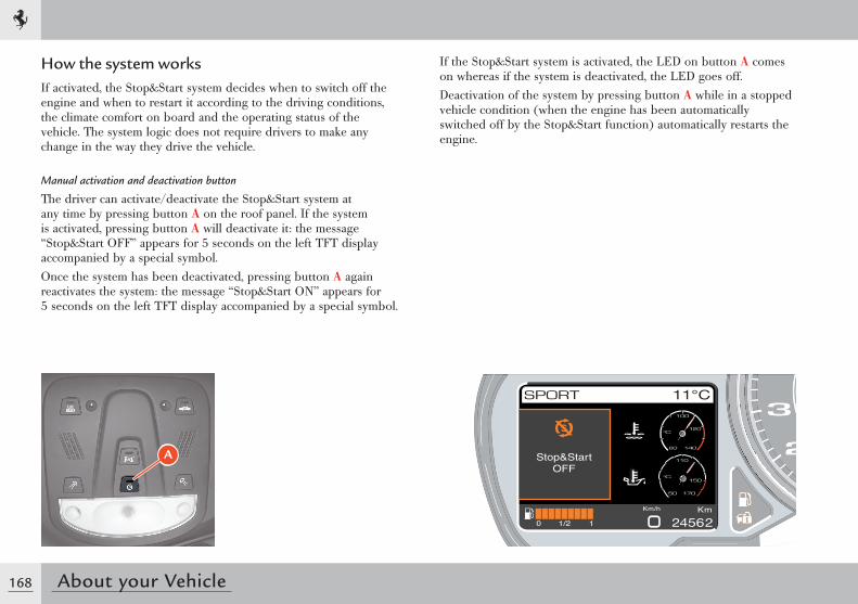
168 About your Vehicle
How the system worksIf activated, the Stop&Start system decides when to switch off the engine and when to restart it according to the driving conditions, the climate comfort on board and the operating status of the vehicle. The system logic does not require drivers to make any change in the way they drive the vehicle.
Manual activation and deactivation button
The driver can activate/deactivate the Stop&Start system at any time by pressing button A on the roof panel. If the system is activated, pressing button A will deactivate it: the message “Stop&Start OFF” appears for 5 seconds on the left TFT display accompanied by a special symbol.Once the system has been deactivated, pressing button A again reactivates the system: the message “Stop&Start ON” appears for 5 seconds on the left TFT display accompanied by a special symbol.
If the Stop&Start system is activated, the LED on button A comes on whereas if the system is deactivated, the LED goes off.Deactivation of the system by pressing button A while in a stopped vehicle condition (when the engine has been automatically switched off by the Stop&Start function) automatically restarts the engine.
Stop&StartOFF
A
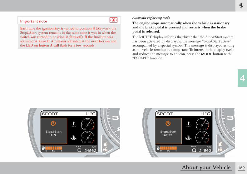
169
4
About your Vehicle
Stop&StartON
Stop&Startactive
Important note
Each time the ignition key is turned to position II (Key-on), the Stop&Start system remains in the same state it was in when the switch was turned to position 0 (Key-off). If the function was activated at Key-off, it remains activated at the next Key-on and the LED on button A will fl ash for a few seconds.
Automatic engine stop mode
The engine stops automatically when the vehicle is stationary and the brake pedal is pressed and restarts when the brake pedal is released.The left TFT display informs the driver that the Stop&Start system has been activated by displaying the message “Stop&Start active” accompanied by a special symbol. The message is displayed as long as the vehicle remains in a stop state. To interrupt the display cycle and reduce the message to an icon, press the MODE button with “ESCAPE” function.
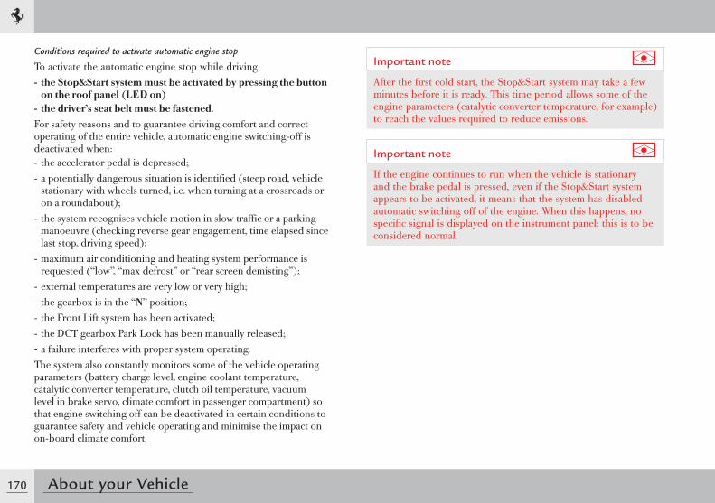
170 About your Vehicle
Conditions required to activate automatic engine stop
To activate the automatic engine stop while driving:- the Stop&Start system must be activated by pressing the button
on the roof panel (LED on)- the driver’s seat belt must be fastened.For safety reasons and to guarantee driving comfort and correct operating of the entire vehicle, automatic engine switching-off is deactivated when:- the accelerator pedal is depressed;- a potentially dangerous situation is identified (steep road, vehicle
stationary with wheels turned, i.e. when turning at a crossroads or on a roundabout);
- the system recognises vehicle motion in slow traffic or a parking manoeuvre (checking reverse gear engagement, time elapsed since last stop, driving speed);
- maximum air conditioning and heating system performance is requested (“low”, “max defrost” or “rear screen demisting”);
- external temperatures are very low or very high;- the gearbox is in the “N” position;- the Front Lift system has been activated;- the DCT gearbox Park Lock has been manually released;- a failure interferes with proper system operating.The system also constantly monitors some of the vehicle operating parameters (battery charge level, engine coolant temperature, catalytic converter temperature, clutch oil temperature, vacuum level in brake servo, climate comfort in passenger compartment) so that engine switching off can be deactivated in certain conditions to guarantee safety and vehicle operating and minimise the impact on on-board climate comfort.
Important note
After the first cold start, the Stop&Start system may take a few minutes before it is ready. This time period allows some of the engine parameters (catalytic converter temperature, for example) to reach the values required to reduce emissions.
Important note
If the engine continues to run when the vehicle is stationary and the brake pedal is pressed, even if the Stop&Start system appears to be activated, it means that the system has disabled automatic switching off of the engine. When this happens, no specific signal is displayed on the instrument panel: this is to be considered normal.
171
4
About your Vehicle
Information on automatic restarting of engine
With the Stop&Start system activated in a stopped vehicle condition, the driver can restart the engine by:- releasing the brake pedal- UP-shifting- engaging reverse gear- pressing the accelerator pedal
Warning
If the engine is switched off accidentally and not by the Stop&Start system, it must be restarted manually by the driver by pressing the ENGINE START button and reengaging the gear using the shift paddles located behind the steering wheel. This condition is indicated on the left TFT display by the message “Press ENGINE START button to restart”, accompanied by an acoustic signal.
For safety reasons and to guarantee comfort when the vehicle is stationary and correct operating of the entire vehicle, the Stop&Start system also automatically restarts the engine when:- the ENGINE START button on the steering wheel has been pressed- the function has been deactivated by pressing the button located
on the roof panel- the driver’s seat belt has been unfastened- the driver-side door has been opened- the hard top is being opened or closed- the Front Lift system has been activated- rear screen demisting has been requested or the air conditioning
and heating system set to “low” or “max defrost”.
The system also constantly monitors some of the vehicle operating parameters (battery charge level, engine coolant temperature, catalytic converter temperature, clutch oil temperature, vacuum level in brake servo, climate comfort in passenger compartment, vehicle speed) so that the engine can be automatically started in certain conditions to guarantee safety and vehicle operating and minimise the impact on on-board climate comfort.
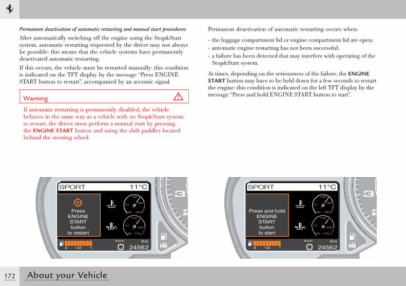
172 About your Vehicle
Permanent deactivation of automatic restarting and manual start procedures
After automatically switching off the engine using the Stop&Start system, automatic restarting requested by the driver may not always be possible: this means that the vehicle systems have permanently deactivated automatic restarting.If this occurs, the vehicle must be restarted manually: this condition is indicated on the TFT display by the message “Press ENGINE START button to restart”, accompanied by an acoustic signal.
Warning
If automatic restarting is permanently disabled, the vehicle behaves in the same way as a vehicle with no Stop&Start system: to restart, the driver must perform a manual start by pressing the ENGINE START button and using the shift paddles located behind the steering wheel.
Permanent deactivation of automatic restarting occurs when:
- the luggage compartment lid or engine compartment lid are open;- automatic engine restarting has not been successful;- a failure has been detected that may interfere with operating of the
Stop&Start system.
At times, depending on the seriousness of the failure, the ENGINE START button may have to be held down for a few seconds to restart the engine: this condition is indicated on the left TFT display by the message “Press and hold ENGINE START button to start”.
PressENGINESTARTbutton
to restart
Press and holdENGINESTARTbuttonto start
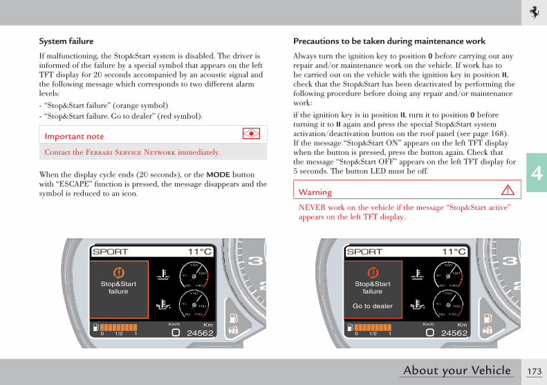
173
4
About your Vehicle
System failure
If malfunctioning, the Stop&Start system is disabled. The driver is informed of the failure by a special symbol that appears on the left TFT display for 20 seconds accompanied by an acoustic signal and the following message which corresponds to two different alarm levels:- “Stop&Start failure” (orange symbol)- “Stop&Start failure. Go to dealer” (red symbol).
Important note
Contact the Ferrari Service Network immediately.
When the display cycle ends (20 seconds), or the MODE button with “ESCAPE” function is pressed, the message disappears and the symbol is reduced to an icon.
Stop&Startfailure
Stop&Startfailure
Go to dealer
Precautions to be taken during maintenance work
Always turn the ignition key to position 0 before carrying out any repair and/or maintenance work on the vehicle. If work has to be carried out on the vehicle with the ignition key in position II, check that the Stop&Start has been deactivated by performing the following procedure before doing any repair and/or maintenance work:if the ignition key is in position II, turn it to position 0 before turning it to II again and press the special Stop&Start system activation/deactivation button on the roof panel (see page 168). If the message “Stop&Start ON” appears on the left TFT display when the button is pressed, press the button again. Check that the message “Stop&Start OFF” appears on the left TFT display for 5 seconds. The button LED must be off.
Warning
NEVER work on the vehicle if the message “Stop&Start active” appears on the left TFT display.
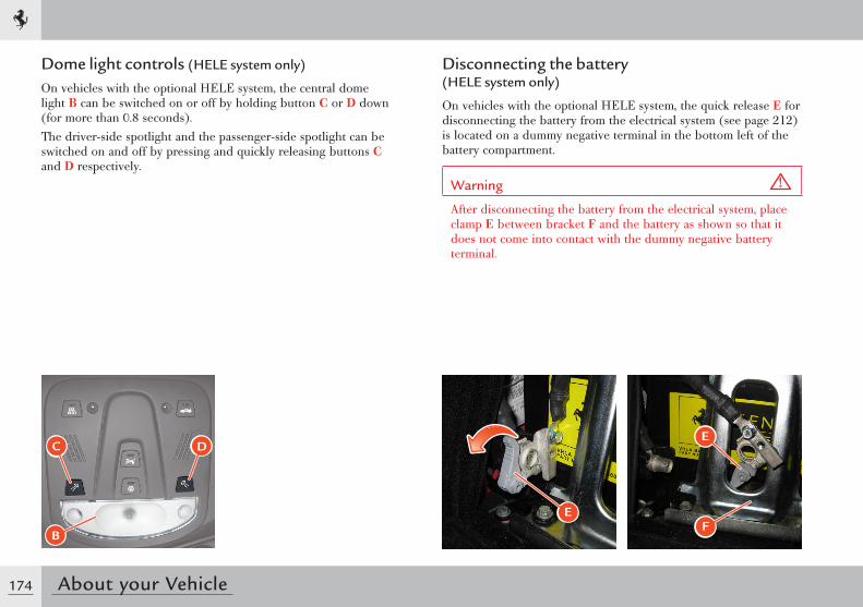
174 About your Vehicle
B
C D
Dome light controls (HELE system only)
On vehicles with the optional HELE system, the central dome light B can be switched on or off by holding button C or D down (for more than 0.8 seconds).The driver-side spotlight and the passenger-side spotlight can be switched on and off by pressing and quickly releasing buttons C and D respectively.
Disconnecting the battery (HELE system only)
On vehicles with the optional HELE system, the quick release E for disconnecting the battery from the electrical system (see page 212) is located on a dummy negative terminal in the bottom left of the battery compartment.
Warning
After disconnecting the battery from the electrical system, place clamp E between bracket F and the battery as shown so that it does not come into contact with the dummy negative battery terminal.
EF
E
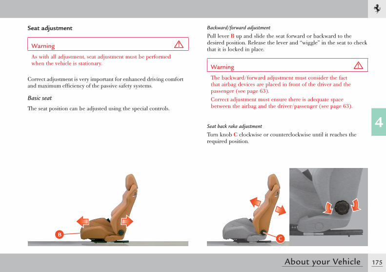
175
4
About your Vehicle
Seat adjustment
Warning
As with all adjustment, seat adjustment must be performed when the vehicle is stationary.
Correct adjustment is very important for enhanced driving comfort and maximum efficiency of the passive safety systems.
Basic seat
The seat position can be adjusted using the special controls.
Backward/forward adjustment
Pull lever B up and slide the seat forward or backward to the desired position. Release the lever and “wiggle” in the seat to check that it is locked in place.
Warning
The backward/forward adjustment must consider the fact that airbag devices are placed in front of the driver and the passenger (see page 63).Correct adjustment must ensure there is adequate space between the airbag and the driver/passenger (see page 63).
Seat back rake adjustment
Turn knob C clockwise or counterclockwise until it reaches the required position.
BC
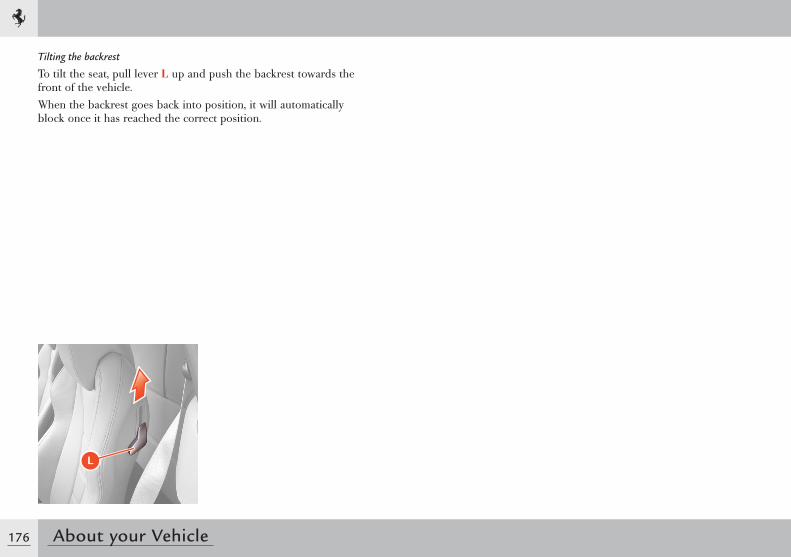
176 About your Vehicle
Tilting the backrest
To tilt the seat, pull lever L up and push the backrest towards the front of the vehicle.When the backrest goes back into position, it will automatically block once it has reached the correct position.
L
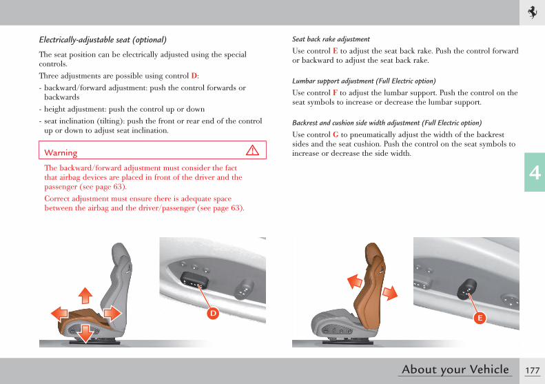
177
4
About your Vehicle
E
Seat back rake adjustment
Use control E to adjust the seat back rake. Push the control forward or backward to adjust the seat back rake.
Lumbar support adjustment (Full Electric option)
Use control F to adjust the lumbar support. Push the control on the seat symbols to increase or decrease the lumbar support.
Backrest and cushion side width adjustment (Full Electric option)
Use control G to pneumatically adjust the width of the backrest sides and the seat cushion. Push the control on the seat symbols to increase or decrease the side width.
D
Electrically-adjustable seat (optional)
The seat position can be electrically adjusted using the special controls.Three adjustments are possible using control D:- backward/forward adjustment: push the control forwards or
backwards- height adjustment: push the control up or down- seat inclination (tilting): push the front or rear end of the control
up or down to adjust seat inclination.
Warning
The backward/forward adjustment must consider the fact that airbag devices are placed in front of the driver and the passenger (see page 63).Correct adjustment must ensure there is adequate space between the airbag and the driver/passenger (see page 63).
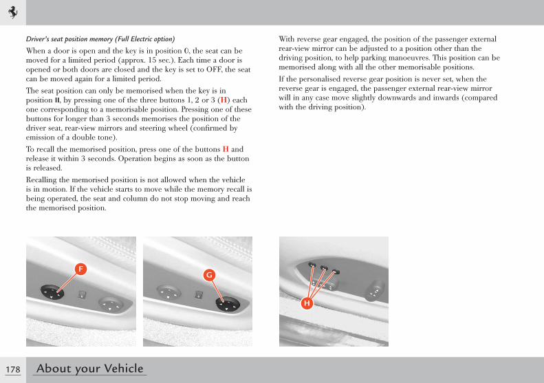
178 About your Vehicle
��
�
Driver’s seat position memory (Full Electric option)
When a door is open and the key is in position 0, the seat can be moved for a limited period (approx. 15 sec.). Each time a door is opened or both doors are closed and the key is set to OFF, the seat can be moved again for a limited period. The seat position can only be memorised when the key is in position II, by pressing one of the three buttons 1, 2 or 3 (H) each one corresponding to a memorisable position. Pressing one of these buttons for longer than 3 seconds memorises the position of the driver seat, rear-view mirrors and steering wheel (confirmed by emission of a double tone).To recall the memorised position, press one of the buttons H and release it within 3 seconds. Operation begins as soon as the button is released.Recalling the memorised position is not allowed when the vehicle is in motion. If the vehicle starts to move while the memory recall is being operated, the seat and column do not stop moving and reach the memorised position.
With reverse gear engaged, the position of the passenger external rear-view mirror can be adjusted to a position other than the driving position, to help parking manoeuvres. This position can be memorised along with all the other memorisable positions. If the personalised reverse gear position is never set, when the reverse gear is engaged, the passenger external rear-view mirror will in any case move slightly downwards and inwards (compared with the driving position).
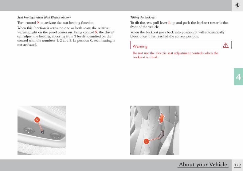
179
4
About your Vehicle
Tilting the backrest
To tilt the seat, pull lever L up and push the backrest towards the front of the vehicle.When the backrest goes back into position, it will automatically block once it has reached the correct position.
Warning
Do not use the electric seat adjustment controls when the backrest is tilted.
L
�
Seat heating system (Full Electric option)
Turn control N to activate the seat heating function.When this function is active on one or both seats, the relative warning light on the panel comes on. Using control N, the driver can adjust the heating, choosing from 3 levels identified on the control with the numbers 1, 2 and 3. In position 0, seat heating is not activated.
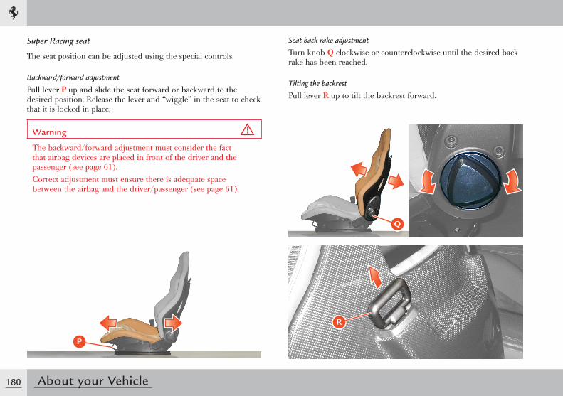
180 About your Vehicle
R
P
Q
Super Racing seat
The seat position can be adjusted using the special controls.
Backward/forward adjustment
Pull lever P up and slide the seat forward or backward to the desired position. Release the lever and “wiggle” in the seat to check that it is locked in place.
Warning
The backward/forward adjustment must consider the fact that airbag devices are placed in front of the driver and the passenger (see page 61).Correct adjustment must ensure there is adequate space between the airbag and the driver/passenger (see page 61).
Seat back rake adjustment
Turn knob Q clockwise or counterclockwise until the desired back rake has been reached.
Tilting the backrest
Pull lever R up to tilt the backrest forward.
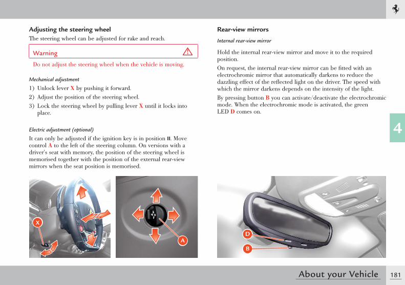
181
4
About your Vehicle
Rear-view mirrors
Internal rear-view mirror
Hold the internal rear-view mirror and move it to the required position.On request, the internal rear-view mirror can be fitted with an electrochromic mirror that automatically darkens to reduce the dazzling effect of the reflected light on the driver. The speed with which the mirror darkens depends on the intensity of the light.By pressing button B you can activate/deactivate the electrochromic mode. When the electrochromic mode is activated, the green LED D comes on.
B
D
Adjusting the steering wheelThe steering wheel can be adjusted for rake and reach.
Warning
Do not adjust the steering wheel when the vehicle is moving.
Mechanical adjustment
1) Unlock lever X by pushing it forward.2) Adjust the position of the steering wheel.3) Lock the steering wheel by pulling lever X until it locks into
place.
Electric adjustment (optional)
It can only be adjusted if the ignition key is in position II. Move control A to the left of the steering column. On versions with a driver's seat with memory, the position of the steering wheel is memorised together with the position of the external rear-view mirrors when the seat position is memorised.
X
A
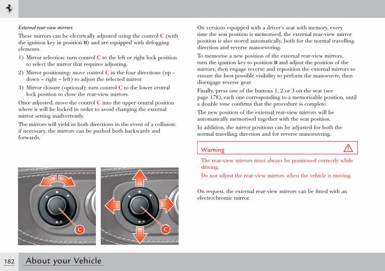
182 About your Vehicle
External rear-view mirrors
These mirrors can be electrically adjusted using the control C (with the ignition key in position II) and are equipped with defogging elements.1) Mirror selection: turn control C to the left or right lock position
to select the mirror that requires adjusting.2) Mirror positioning: move control C in the four directions (up –
down – right – left) to adjust the selected mirror.3) Mirror closure (optional): turn control C to the lower central
lock position to close the rear-view mirrors.Once adjusted, move the control C into the upper central position where it will be locked in order to avoid changing the external mirror setting inadvertently.The mirrors will yield in both directions in the event of a collision: if necessary, the mirrors can be pushed both backwards and forwards.
On versions equipped with a driver's seat with memory, every time the seat position is memorised, the external rear-view mirror position is also stored automatically, both for the normal travelling direction and reverse manoeuvring.To memorise a new position of the external rear-view mirrors, turn the ignition key to position II and adjust the position of the mirrors; then engage reverse and reposition the external mirrors to ensure the best possible visibility to perform the manoeuvre, then disengage reverse gear.Finally, press one of the buttons 1, 2 or 3 on the seat (see page 178), each one corresponding to a memorisable position, until a double tone confirms that the procedure is complete. The new position of the external rear-view mirrors will be automatically memorised together with the seat position.In addition, the mirror positions can be adjusted for both the normal travelling direction and for reverse manoeuvring.
Warning
The rear-view mirrors must always be positioned correctly while driving.Do not adjust the rear-view mirrors when the vehicle is moving.
On request, the external rear-view mirrors can be fitted with an electrochromic mirror.
C C
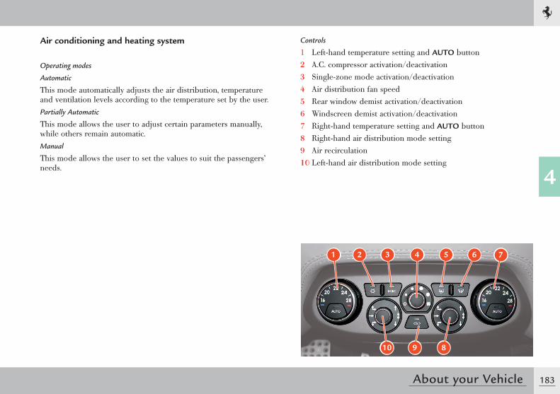
183
4
About your Vehicle
Air conditioning and heating system
Operating modes
Automatic
This mode automatically adjusts the air distribution, temperature and ventilation levels according to the temperature set by the user.Partially Automatic
This mode allows the user to adjust certain parameters manually, while others remain automatic.Manual
This mode allows the user to set the values to suit the passengers’ needs.
Controls
1 Left-hand temperature setting and AUTO button2 A.C. compressor activation/deactivation3 Single-zone mode activation/deactivation4 Air distribution fan speed5 Rear window demist activation/deactivation6 Windscreen demist activation/deactivation7 Right-hand temperature setting and AUTO button8 Right-hand air distribution mode setting9 Air recirculation10 Left-hand air distribution mode setting
1 2 3 5 64
10 9 8
7
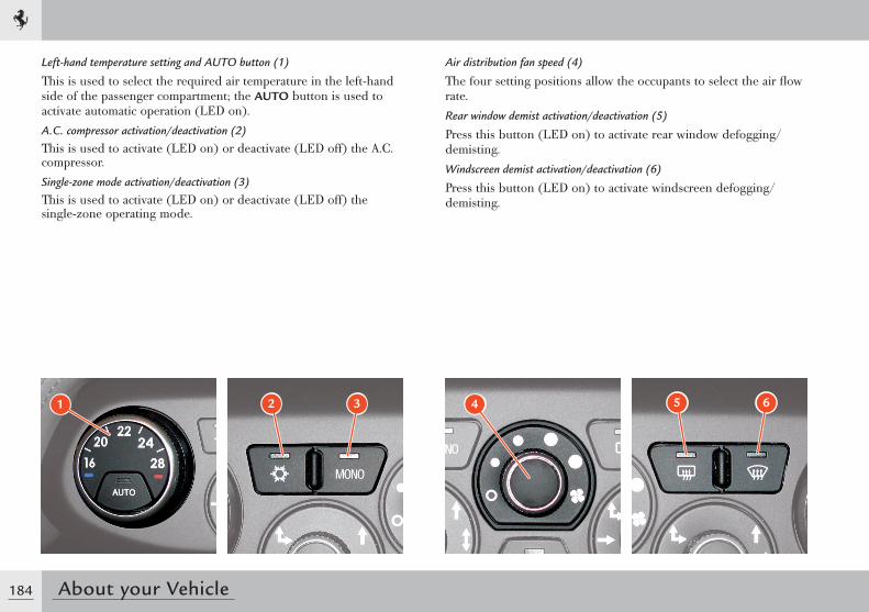
184 About your Vehicle
Left-hand temperature setting and AUTO button (1)
This is used to select the required air temperature in the left-hand side of the passenger compartment; the AUTO button is used to activate automatic operation (LED on).A.C. compressor activation/deactivation (2)
This is used to activate (LED on) or deactivate (LED off) the A.C. compressor.Single-zone mode activation/deactivation (3)
This is used to activate (LED on) or deactivate (LED off) the single-zone operating mode.
Air distribution fan speed (4)
The four setting positions allow the occupants to select the air flow rate.Rear window demist activation/deactivation (5)
Press this button (LED on) to activate rear window defogging/demisting.Windscreen demist activation/deactivation (6)
Press this button (LED on) to activate windscreen defogging/demisting.
2 31 4 5 6
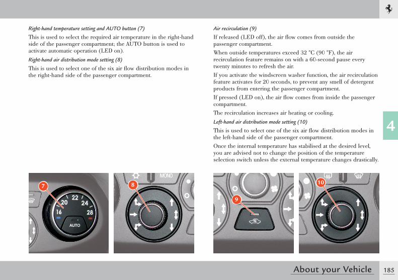
185
4
About your Vehicle
Right-hand temperature setting and AUTO button (7)
This is used to select the required air temperature in the right-hand side of the passenger compartment; the AUTO button is used to activate automatic operation (LED on).Right-hand air distribution mode setting (8)
This is used to select one of the six air flow distribution modes in the right-hand side of the passenger compartment.
Air recirculation (9)
If released (LED off), the air flow comes from outside the passenger compartment.When outside temperatures exceed 32 °C (90 °F), the air recirculation feature remains on with a 60-second pause every twenty minutes to refresh the air. If you activate the windscreen washer function, the air recirculation feature activates for 20 seconds, to prevent any smell of detergent products from entering the passenger compartment.If pressed (LED on), the air flow comes from inside the passenger compartment.The recirculation increases air heating or cooling.Left-hand air distribution mode setting (10)
This is used to select one of the six air flow distribution modes in the left-hand side of the passenger compartment.Once the internal temperature has stabilised at the desired level, you are advised not to change the position of the temperature selection switch unless the external temperature changes drastically.
7 8
9
10
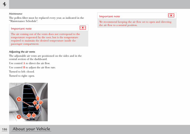
186 About your Vehicle
Maintenance
The pollen filter must be replaced every year, as indicated in the “Maintenance Schedule”.
Important note
The air coming out of the vents does not correspond to the temperature requested by the user, but is the temperature required to maintain the desired temperature inside the passenger compartment.
Adjusting the air vents
The adjustable air vents are positioned on the sides and in the central section of the dashboard.Use control A to direct the air flow.Use control B to adjust the air flow rate.Turned to left: closed.Turned to right: open.
Important note
We recommend keeping the air flow set to open and directing the air flow to a neutral position.
A
B
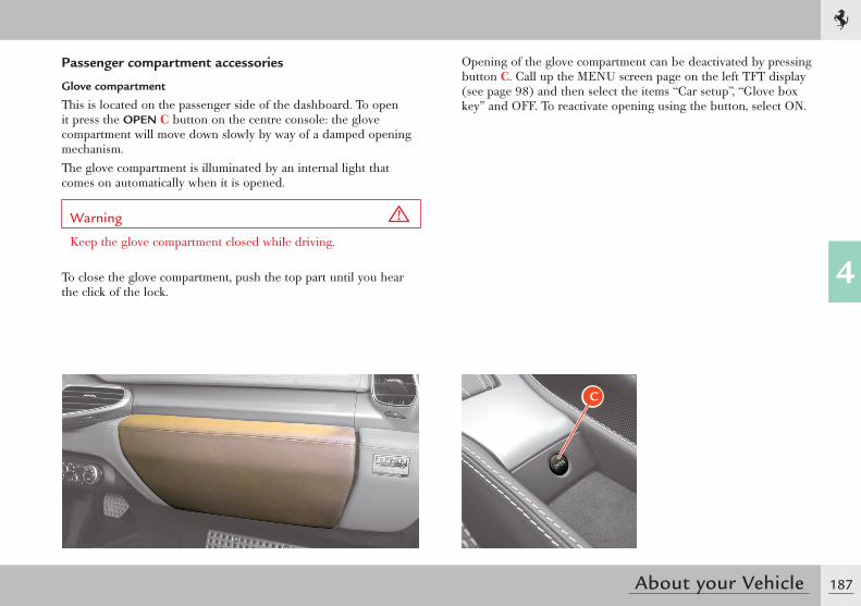
187
4
About your Vehicle
Passenger compartment accessories
Glove compartment
This is located on the passenger side of the dashboard. To open it press the OPEN C button on the centre console: the glove compartment will move down slowly by way of a damped opening mechanism.The glove compartment is illuminated by an internal light that comes on automatically when it is opened.
Warning
Keep the glove compartment closed while driving.
To close the glove compartment, push the top part until you hear the click of the lock.
Opening of the glove compartment can be deactivated by pressing button C. Call up the MENU screen page on the left TFT display (see page 98) and then select the items “Car setup”, “Glove box key” and OFF. To reactivate opening using the button, select ON.
C
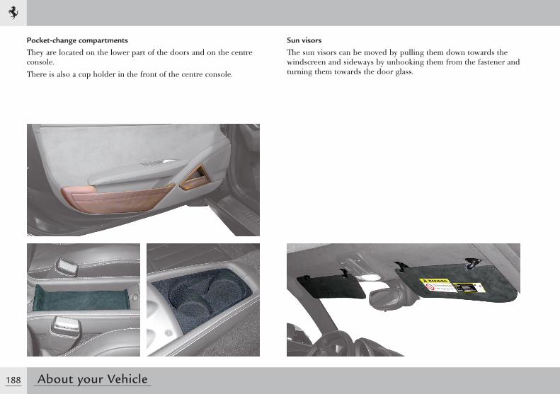
188 About your Vehicle
Pocket-change compartments
They are located on the lower part of the doors and on the centre console.There is also a cup holder in the front of the centre console.
Sun visors
The sun visors can be moved by pulling them down towards the windscreen and sideways by unhooking them from the fastener and turning them towards the door glass.
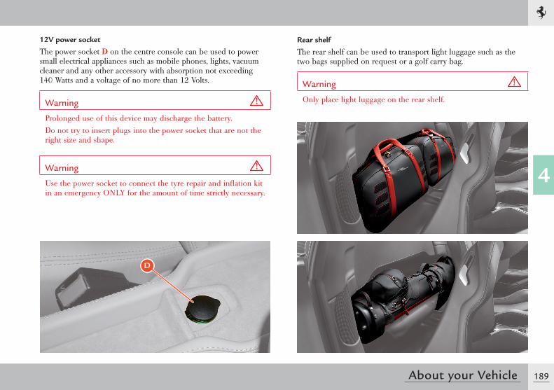
189
4
About your Vehicle
12V power socket
The power socket D on the centre console can be used to power small electrical appliances such as mobile phones, lights, vacuum cleaner and any other accessory with absorption not exceeding 140 Watts and a voltage of no more than 12 Volts.
Warning
Prolonged use of this device may discharge the battery.Do not try to insert plugs into the power socket that are not the right size and shape.
Warning
Use the power socket to connect the tyre repair and inflation kit in an emergency ONLY for the amount of time strictly necessary.
D
Rear shelf
The rear shelf can be used to transport light luggage such as the two bags supplied on request or a golf carry bag.
Warning
Only place light luggage on the rear shelf.
Toolkit ................................................................ 192Replacing light bulbs ........................................... 197Replacing a fuse .................................................. 200Replacing a wheel ................................................ 208Towing ................................................................ 210Battery ................................................................ 212Battery conditioner .............................................. 216EPB emergency release ......................................... 220Park Lock emergency release ................................ 222
ADVICE FOR EMERGENCY SITUATIONS
5
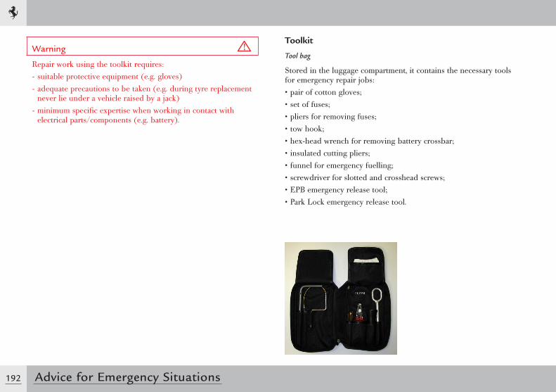
192 Advice for Emergency Situations
Warning
Repair work using the toolkit requires:- suitable protective equipment (e.g. gloves)- adequate precautions to be taken (e.g. during tyre replacement
never lie under a vehicle raised by a jack)- minimum specific expertise when working in contact with
electrical parts/components (e.g. battery).
Toolkit
Tool bag
Stored in the luggage compartment, it contains the necessary tools for emergency repair jobs:• pair of cotton gloves;• set of fuses;• pliers for removing fuses;• tow hook;• hex-head wrench for removing battery crossbar;• insulated cutting pliers;• funnel for emergency fuelling;• screwdriver for slotted and crosshead screws;• EPB emergency release tool;• Park Lock emergency release tool.
193
5
Advice for Emergency Situations
Warning
The Electric Parking Brake (EPB) emergency release tool and the Park Lock emergency release tool may only be used by specialised workshop personnel, as indicated on the label in the tool bag.
Warning
The Electric Parking Brake (EPB) emergency release tool is flexible and is kept folded up in the tool bag: remove the tool from its housing very carefully to prevent the end flying out.
194 Advice for Emergency Situations
Emergency tyre repair and inflation kit
Stored in the luggage compartment, it can be used in the event of a puncture or low tyre pressure to repair and/or inflate a tyre enough to continue the journey safely.
Important note
To use the tyre repair and inflation kit correctly, refer to the instruction booklet supplied with the kit.
Warning
Give the instruction manual supplied with the kit to the personnel that will handle the tyre repaired with the tyre repair kit.
Warning
In the event of a puncture caused by foreign objects, tyres can be repaired with cuts of up to 4 mm in diameter on the tyre tread and shoulder.
Warning
Punctures cannot be repaired on the sides of the tyre. Do not use the tyre repair kit if the tyre has been damaged after driving with a flat tyre.
Warning
Damage to the wheel rim that causes air leaks cannot be repaired. Do not remove foreign objects (screws or nails) that have penetrated the tyre.
Warning
After using the repair kit, the vehicle must be considered in an emergency situation: drive with the greatest care (maximum permissible speed 80 km/h - 50 mph).
Warning
Apply the sticker supplied with the kit where it can easily be seen by the driver to indicate that the tyre has been treated with the tyre repair kit.Drive carefully especially on bends.Avoid sudden accelerations or braking.
Warning
The kit is to be used to temporarily repair only one tyre punctured by small objects: the kit may not be useful in the case of large punctures or tearing.
195
5
Advice for Emergency Situations
Important note
After driving for approximately 10 minutes, stop and recheck the tyre pressure. Remember to apply the parking brake.
Warning
If the pressure has decreased below 1.8 bar (26.11 psi), do not continue driving: the kit cannot guarantee the correct hold because the tyre is too damaged. Contact the Ferrari Service Network. If the tyre pressure is at least 1.8 bar (26.11 psi), restore the correct pressure and continue driving.Drive very carefully to the nearest Ferrari Service Network.
Warning
The repaired tyre must be replaced as soon as possible and the workshop personnel must be informed that the tyre was treated with tyre repair fluid.
Warning
Keep the kit in its box and out of children’s reach. Do not inhale or swallow the fluid contained in the cartridge and avoid contact with the skin and eyes.
Warning
The spray contains ethylene glycol and latex.The latex may cause an allergic reaction, is harmful if swallowed and is irritating to eyes. May cause sensitisation by inhalation and skin contact. Avoid contact with eyes, skin and clothing. In case of contact, rinse immediately with plenty of water. If swallowed, do not induce vomiting, rinse mouth, drink plenty of water and seek immediate medical advice. Keep out of reach of children. The product should not be used by asthma sufferers. Do not inhale vapours during use. In the event of an allergic reaction, seek immediate medical advice. Store the spray can in its special case away from sources of heat. The liquid sealant has an expiry date: the expiry date is indicated on the kit.
196 Advice for Emergency Situations
Environment
Replace the spray can containing the expired liquid sealant. Do not dispose of the spray can and sealant in normal domestic waste. Dispose of in accordance with national and local regulations or ask the Ferrari Service Network to take care of disposal.
Warning
The sealant in the kit cartridge can damage the sensor inside the wheel rim on vehicles fitted with a tyre temperature and pressure monitoring system (TPMS).If this occurs, the sensor must be replaced. Contact the Ferrari Service Network.
Warning
Wear the protective gloves supplied with the tyre inflation and repair kit.
Useful accessories
In addition to the tools supplied with the vehicle, the hazard warning triangle and fluorescent safety jacket should always be kept on board in order to signal hazardous situations in compliance with regulations.
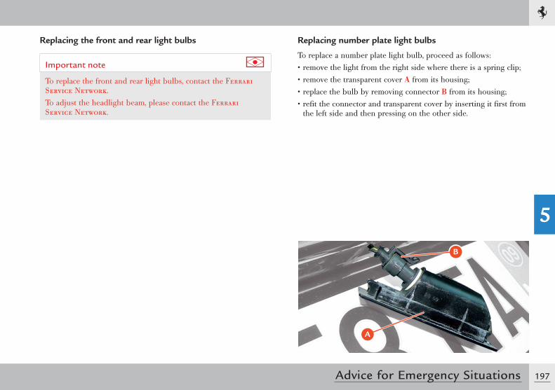
197
5
Advice for Emergency Situations
Replacing the front and rear light bulbs
Important note
To replace the front and rear light bulbs, contact the Ferrari Service Network.To adjust the headlight beam, please contact the Ferrari Service Network.
Replacing number plate light bulbs
To replace a number plate light bulb, proceed as follows:• remove the light from the right side where there is a spring clip;• remove the transparent cover A from its housing;• replace the bulb by removing connector B from its housing;• refit the connector and transparent cover by inserting it first from
the left side and then pressing on the other side.
A
B
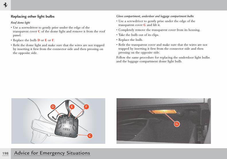
198 Advice for Emergency Situations
Replacing other light bulbs
Roof dome light
• Use a screwdriver to gently prise under the edge of the transparent cover C of the dome light and remove it from the roof panel.
• Replace the bulb D or E or F.• Refit the dome light and make sure that the wires are not trapped
by inserting it first from the connector side and then pressing on the opposite side.
Glove compartment, underdoor and luggage compartment bulbs
• Use a screwdriver to gently prise under the edge of the transparent cover G and lift it.
• Completely remove the transparent cover from its housing.• Take the bulb out of its clips.• Replace the bulb.• Refit the transparent cover and make sure that the wires are not
trapped by inserting it first from the connector side and then pressing on the opposite side.
Follow the same procedure for replacing the underdoor light bulbs and the luggage compartment dome light bulb.
� � �
�
G
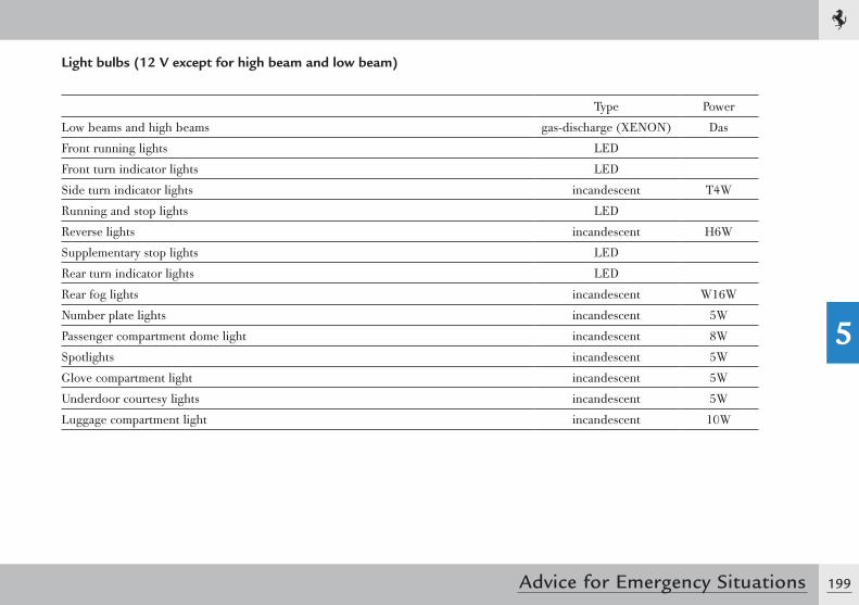
199
5
Advice for Emergency Situations
Light bulbs (12 V except for high beam and low beam)
Type Power
Low beams and high beams gas-discharge (XENON) Das
Front running lights LED
Front turn indicator lights LED
Side turn indicator lights incandescent T4W
Running and stop lights LED
Reverse lights incandescent H6W
Supplementary stop lights LED
Rear turn indicator lights LED
Rear fog lights incandescent W16W
Number plate lights incandescent 5W
Passenger compartment dome light incandescent 8W
Spotlights incandescent 5W
Glove compartment light incandescent 5W
Underdoor courtesy lights incandescent 5W
Luggage compartment light incandescent 10W
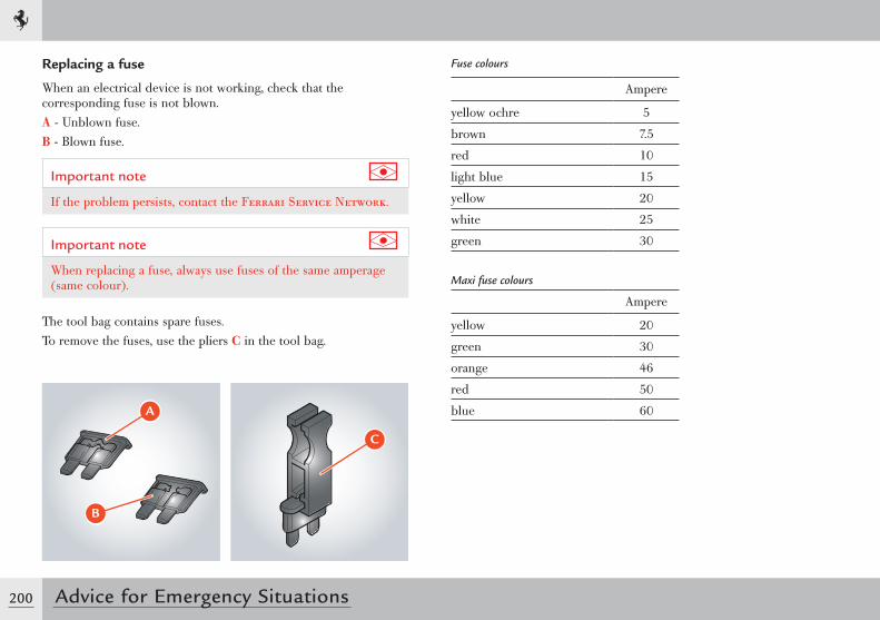
200 Advice for Emergency Situations
Replacing a fuse
When an electrical device is not working, check that the corresponding fuse is not blown.A - Unblown fuse.B - Blown fuse.
Important note
If the problem persists, contact the Ferrari Service Network.
Important note
When replacing a fuse, always use fuses of the same amperage (same colour).
The tool bag contains spare fuses.To remove the fuses, use the pliers C in the tool bag.
�
�
�
Fuse colours
Ampere
yellow ochre 5
brown 7.5
red 10
light blue 15
yellow 20
white 25
green 30
Maxi fuse colours
Ampere
yellow 20
green 30
orange 46
red 50
blue 60
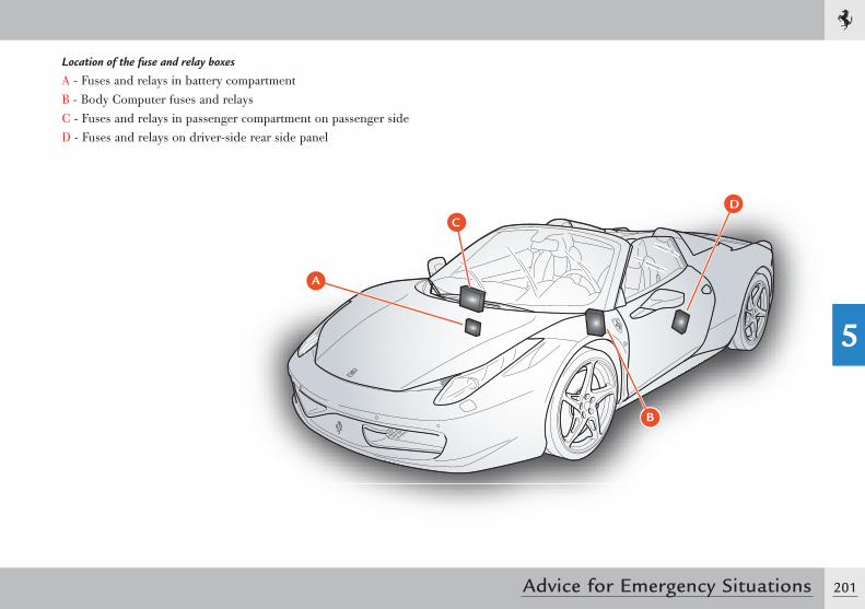
201
5
Advice for Emergency Situations
Location of the fuse and relay boxes
A - Fuses and relays in battery compartmentB - Body Computer fuses and relaysC - Fuses and relays in passenger compartment on passenger sideD - Fuses and relays on driver-side rear side panel
A
CD
B
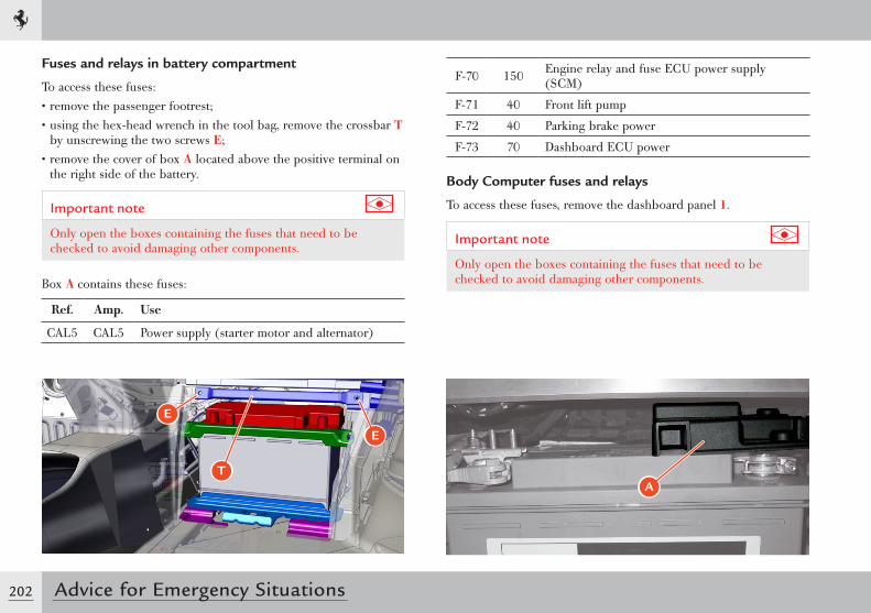
202 Advice for Emergency Situations
Fuses and relays in battery compartment
To access these fuses:• remove the passenger footrest;• using the hex-head wrench in the tool bag, remove the crossbar T
by unscrewing the two screws E;• remove the cover of box A located above the positive terminal on
the right side of the battery.
Important note
Only open the boxes containing the fuses that need to be checked to avoid damaging other components.
Box A contains these fuses:
Ref. Amp. Use
CAL5 CAL5 Power supply (starter motor and alternator)
F-70 150 Engine relay and fuse ECU power supply (SCM)
F-71 40 Front lift pump
F-72 40 Parking brake power
F-73 70 Dashboard ECU power
Body Computer fuses and relays
To access these fuses, remove the dashboard panel 1.
Important note
Only open the boxes containing the fuses that need to be checked to avoid damaging other components.
A
E
E
T
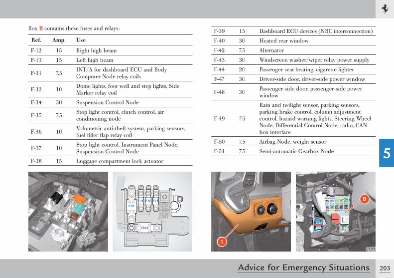
203
5
Advice for Emergency Situations
Box B contains these fuses and relays:
Ref. Amp. Use
F-12 15 Right high beam
F-13 15 Left high beam
F-31 7.5 INT/A for dashboard ECU and Body Computer Node relay coils
F-32 10 Dome lights, foot well and step lights, Side Marker relay coil
F-34 30 Suspension Control Node
F-35 7.5 Stop light control, clutch control, air conditioning node
F-36 10 Volumetric anti-theft system, parking sensors, fuel filler flap relay coil
F-37 10 Stop light control, Instrument Panel Node, Suspension Control Node
F-38 15 Luggage compartment lock actuator
F-39 15 Dashboard ECU devices (NBC interconnection)
F-40 30 Heated rear window
F-42 7.5 Alternator
F-43 30 Windscreen washer/wiper relay power supply
F-44 20 Passenger seat heating, cigarette lighter
F-47 30 Driver-side door, driver-side power window
F-48 30 Passenger-side door, passenger-side power window
F-49 7.5
Rain and twilight sensor, parking sensors, parking brake control, column adjustment control, hazard warning lights, Steering Wheel Node, Differential Control Node, radio, CAN box interface
F-50 7.5 Airbag Node, weight sensor
F-51 7.5 Semi-automatic Gearbox Node
1
B
F-70
F-73
F-72
F71
F-70
CAL2CAL5
F-73F-72F-71
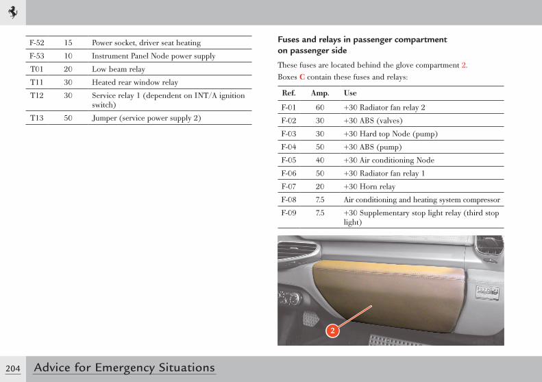
204 Advice for Emergency Situations
Fuses and relays in passenger compartment on passenger side
These fuses are located behind the glove compartment 2.Boxes C contain these fuses and relays:
Ref. Amp. Use
F-01 60 +30 Radiator fan relay 2
F-02 30 +30 ABS (valves)
F-03 30 +30 Hard top Node (pump)
F-04 50 +30 ABS (pump)
F-05 40 +30 Air conditioning Node
F-06 50 +30 Radiator fan relay 1
F-07 20 +30 Horn relay
F-08 7.5 Air conditioning and heating system compressor
F-09 7.5 +30 Supplementary stop light relay (third stop light)
2
F-52 15 Power socket, driver seat heating
F-53 10 Instrument Panel Node power supply
T01 20 Low beam relay
T11 30 Heated rear window relay
T12 30 Service relay 1 (dependent on INT/A ignition switch)
T13 50 Jumper (service power supply 2)
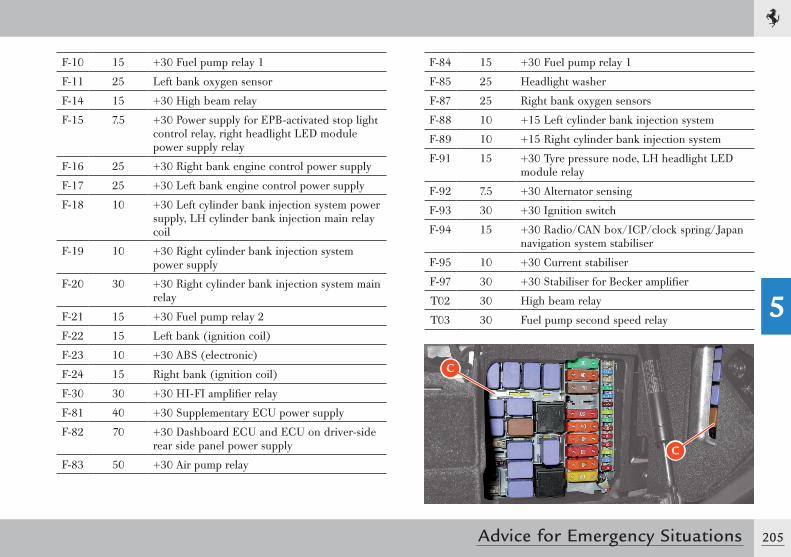
205
5
Advice for Emergency Situations
F-84 15 +30 Fuel pump relay 1
F-85 25 Headlight washer
F-87 25 Right bank oxygen sensors
F-88 10 +15 Left cylinder bank injection system
F-89 10 +15 Right cylinder bank injection system
F-91 15 +30 Tyre pressure node, LH headlight LED module relay
F-92 7.5 +30 Alternator sensing
F-93 30 +30 Ignition switch
F-94 15 +30 Radio/CAN box/ICP/clock spring/Japan navigation system stabiliser
F-95 10 +30 Current stabiliser
F-97 30 +30 Stabiliser for Becker amplifier
T02 30 High beam relay
T03 30 Fuel pump second speed relay
C
C
F-10 15 +30 Fuel pump relay 1
F-11 25 Left bank oxygen sensor
F-14 15 +30 High beam relay
F-15 7.5 +30 Power supply for EPB-activated stop light control relay, right headlight LED module power supply relay
F-16 25 +30 Right bank engine control power supply
F-17 25 +30 Left bank engine control power supply
F-18 10 +30 Left cylinder bank injection system power supply, LH cylinder bank injection main relay coil
F-19 10 +30 Right cylinder bank injection system power supply
F-20 30 +30 Right cylinder bank injection system main relay
F-21 15 +30 Fuel pump relay 2
F-22 15 Left bank (ignition coil)
F-23 10 +30 ABS (electronic)
F-24 15 Right bank (ignition coil)
F-30 30 +30 HI-FI amplifier relay
F-81 40 +30 Supplementary ECU power supply
F-82 70 +30 Dashboard ECU and ECU on driver-side rear side panel power supply
F-83 50 +30 Air pump relay
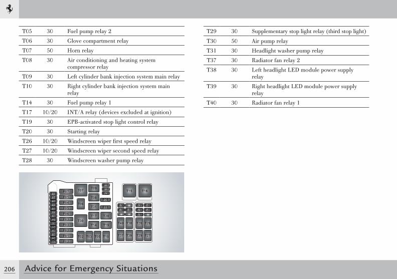
206 Advice for Emergency Situations
T29 30 Supplementary stop light relay (third stop light)
T30 50 Air pump relay
T31 30 Headlight washer pump relay
T37 30 Radiator fan relay 2
T38 30 Left headlight LED module power supply relay
T39 30 Right headlight LED module power supply relay
T40 30 Radiator fan relay 1
T05 30 Fuel pump relay 2
T06 30 Glove compartment relay
T07 50 Horn relay
T08 30 Air conditioning and heating system compressor relay
T09 30 Left cylinder bank injection system main relay
T10 30 Right cylinder bank injection system main relay
T14 30 Fuel pump relay 1
T17 10/20 INT/A relay (devices excluded at ignition)
T19 30 EPB-activated stop light control relay
T20 30 Starting relay
T26 10/20 Windscreen wiper first speed relay
T27 10/20 Windscreen wiper second speed relay
T28 30 Windscreen washer pump relay
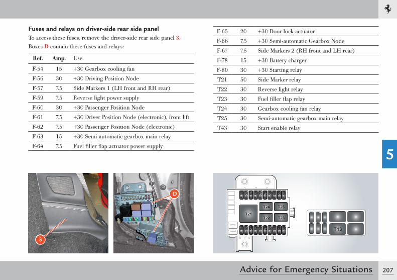
207
5
Advice for Emergency Situations
F-65 20 +30 Door lock actuator
F-66 7.5 +30 Semi-automatic Gearbox Node
F-67 7.5 Side Markers 2 (RH front and LH rear)
F-78 15 +30 Battery charger
F-80 30 +30 Starting relay
T21 50 Side Marker relay
T22 30 Reverse light relay
T23 30 Fuel filler flap relay
T24 30 Gearbox cooling fan relay
T25 30 Semi-automatic gearbox main relay
T43 30 Start enable relay
Fuses and relays on driver-side rear side panelTo access these fuses, remove the driver-side rear side panel 3.Boxes D contain these fuses and relays:
Ref. Amp. Use
F-54 15 +30 Gearbox cooling fan
F-56 30 +30 Driving Position Node
F-57 7.5 Side Markers 1 (LH front and RH rear)
F-59 7.5 Reverse light power supply
F-60 30 +30 Passenger Position Node
F-61 7.5 +30 Driver Position Node (electronic), front lift
F-62 7.5 +30 Passenger Position Node (electronic)
F-63 15 +30 Semi-automatic gearbox main relay
F-64 7.5 Fuel filler flap actuator power supply
3
D
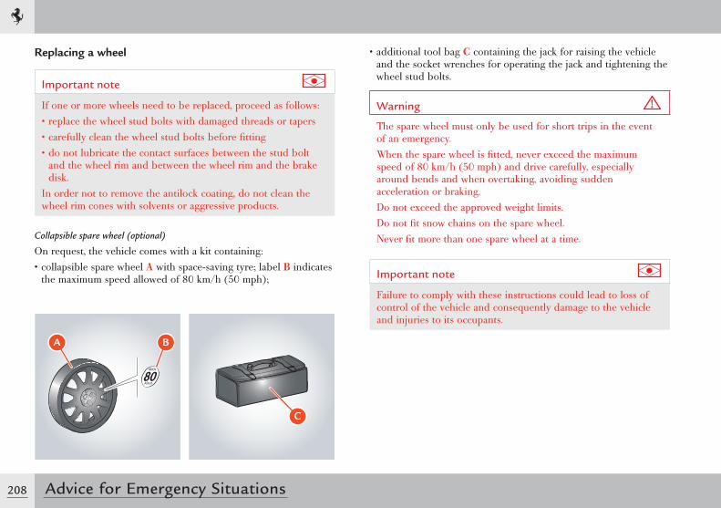
208 Advice for Emergency Situations
Replacing a wheel
Important note
If one or more wheels need to be replaced, proceed as follows:• replace the wheel stud bolts with damaged threads or tapers• carefully clean the wheel stud bolts before fitting• do not lubricate the contact surfaces between the stud bolt
and the wheel rim and between the wheel rim and the brake disk.
In order not to remove the antilock coating, do not clean the wheel rim cones with solvents or aggressive products.
Collapsible spare wheel (optional)
On request, the vehicle comes with a kit containing:• collapsible spare wheel A with space-saving tyre; label B indicates
the maximum speed allowed of 80 km/h (50 mph);
• additional tool bag C containing the jack for raising the vehicle and the socket wrenches for operating the jack and tightening the wheel stud bolts.
Warning
The spare wheel must only be used for short trips in the event of an emergency.When the spare wheel is fitted, never exceed the maximum speed of 80 km/h (50 mph) and drive carefully, especially around bends and when overtaking, avoiding sudden acceleration or braking.Do not exceed the approved weight limits.Do not fit snow chains on the spare wheel.Never fit more than one spare wheel at a time.
Important note
Failure to comply with these instructions could lead to loss of control of the vehicle and consequently damage to the vehicle and injuries to its occupants.
� �
�
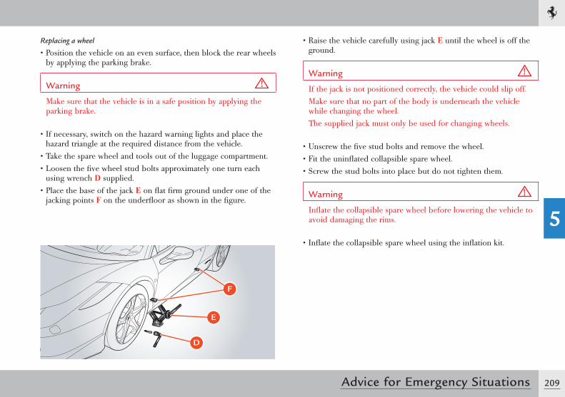
209
5
Advice for Emergency Situations
Replacing a wheel
• Position the vehicle on an even surface, then block the rear wheels by applying the parking brake.
Warning
Make sure that the vehicle is in a safe position by applying the parking brake.
• If necessary, switch on the hazard warning lights and place the hazard triangle at the required distance from the vehicle.
• Take the spare wheel and tools out of the luggage compartment.• Loosen the five wheel stud bolts approximately one turn each
using wrench D supplied.• Place the base of the jack E on flat firm ground under one of the
jacking points F on the underfloor as shown in the figure.
• Raise the vehicle carefully using jack E until the wheel is off the ground.
Warning
If the jack is not positioned correctly, the vehicle could slip off.Make sure that no part of the body is underneath the vehicle while changing the wheel.The supplied jack must only be used for changing wheels.
• Unscrew the five stud bolts and remove the wheel.• Fit the uninflated collapsible spare wheel.• Screw the stud bolts into place but do not tighten them.
Warning
Inflate the collapsible spare wheel before lowering the vehicle to avoid damaging the rims.
• Inflate the collapsible spare wheel using the inflation kit.
D
E
F
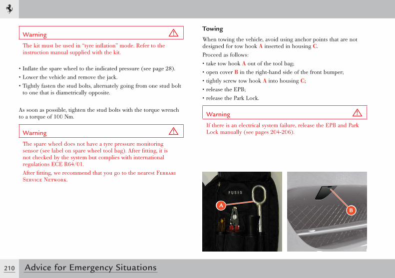
210 Advice for Emergency Situations
Towing
When towing the vehicle, avoid using anchor points that are not designed for tow hook A inserted in housing C.Proceed as follows:• take tow hook A out of the tool bag;• open cover B in the right-hand side of the front bumper;• tightly screw tow hook A into housing C;• release the EPB;• release the Park Lock.
Warning
If there is an electrical system failure, release the EPB and Park Lock manually (see pages 204-206).
Warning
The kit must be used in “tyre inflation” mode. Refer to the instruction manual supplied with the kit.
• Inflate the spare wheel to the indicated pressure (see page 28).• Lower the vehicle and remove the jack.• Tightly fasten the stud bolts, alternately going from one stud bolt
to one that is diametrically opposite.
As soon as possible, tighten the stud bolts with the torque wrench to a torque of 100 Nm.
Warning
The spare wheel does not have a tyre pressure monitoring sensor (see label on spare wheel tool bag). After fitting, it is not checked by the system but complies with international regulations ECE R64/01.After fitting, we recommend that you go to the nearest Ferrari Service Network.
AB
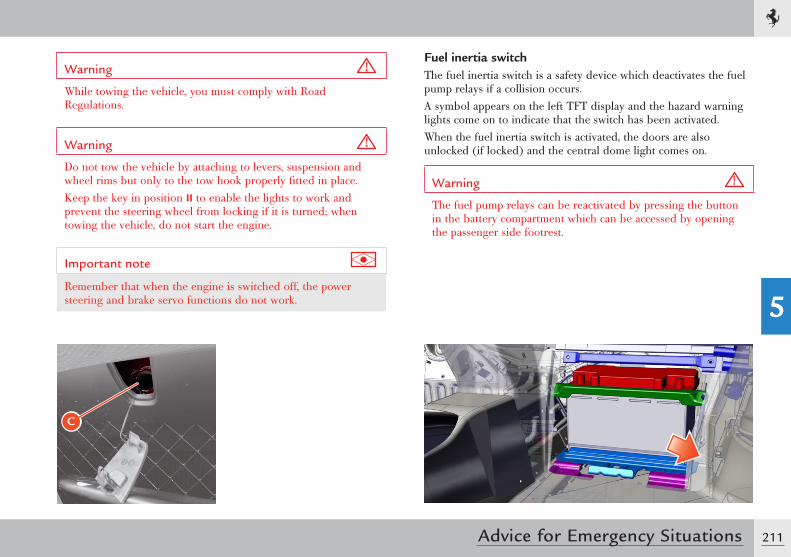
211
5
Advice for Emergency Situations
Warning
While towing the vehicle, you must comply with Road Regulations.
Warning
Do not tow the vehicle by attaching to levers, suspension and wheel rims but only to the tow hook properly fitted in place.Keep the key in position II to enable the lights to work and prevent the steering wheel from locking if it is turned; when towing the vehicle, do not start the engine.
Important note
Remember that when the engine is switched off, the power steering and brake servo functions do not work.
C
Fuel inertia switchThe fuel inertia switch is a safety device which deactivates the fuel pump relays if a collision occurs.A symbol appears on the left TFT display and the hazard warning lights come on to indicate that the switch has been activated.When the fuel inertia switch is activated, the doors are also unlocked (if locked) and the central dome light comes on.
Warning
The fuel pump relays can be reactivated by pressing the button in the battery compartment which can be accessed by opening the passenger side footrest.
212 Advice for Emergency Situations
Disconnecting the battery
Before disconnecting the battery, deactivate the electronic alarm using the remote control.
Warning
Never disconnect the battery from the electrical system when the engine is running.Before disconnecting the battery, lower the side windows by at least 2-3 centimetres (0.8-1.2. in.) to avoid damaging the strips when opening and closing the doors.
Warning
When the battery is connected and charged, this operation is automatically performed when the doors are opened and closed. The windows must remain lowered until the charged battery is reconnected. If the battery is discharged and the windows are fully up, only open the doors when strictly necessary and take great care; do not close them again until the windows can be lowered.
Important note
We recommend using the battery conditioner if the vehicle is going to left unused for a long period.
To cut off the power supply from the battery to the electrical system, use the quick release C on the left side of the battery. Use the locking lever to loosen the terminal.
Battery
The battery is located in the passenger compartment behind the passenger side footrest.
Checking the battery
Warning
The battery does not need topping up with distilled water or sulphuric acid.
Warning
The battery must only be removed from the vehicle by the Ferrari Service Network.
Warning
Do not place the battery near sources of heat, sparks or naked flames.
The vehicle is equipped with a sealed lead acid battery that does not require maintenance.• Periodically check that the terminals and pins are clean and firmly
secured.• Visually inspect the outer casing for any cracks.• If the battery overcharges, it will wear out quickly. Have the
vehicle electrical system checked if the battery tends to discharge easily.
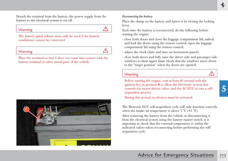
213
5
Advice for Emergency Situations
Detach the terminal from the battery: the power supply from the battery to the electrical system is cut off.
Warning
The battery quick release must only be used if the battery conditioner cannot be connected.
Warning
Place the terminal so that it does not come into contact with the battery terminal or other metal parts of the vehicle.
C
Reconnecting the battery
Place the clamp on the battery and fasten it by closing the locking lever.Each time the battery is reconnected, do the following before starting the engine:- close both doors and close the luggage compartment lid; unlock
and lock the doors using the remote control; open the luggage compartment lid using the remote control;
- adjust the clock (date and time on instrument panel);- close both doors and fully raise the driver side and passenger side
windows to their upper limit; check that the windows move down to the “target position” when the doors are opened.
Warning
Before starting the engine, wait at least 60 second with the ignition key in position II to allow the electronic system that controls the motor-driven valves and the AC ECU to run a self-acquisition process.During this period, no devices must be activated.
The Motronic ECU self-acquisition cycle will only function correctly when the intake air temperature is above 5 °C (41 °F).After removing the battery from the vehicle or disconnecting it from the electrical system using the battery master switch, it is important to check that the external temperature is within the indicated values when reconnecting before performing the self-acquisition cycle.
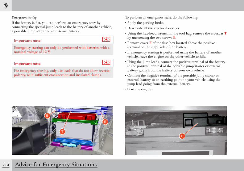
214 Advice for Emergency Situations
Emergency starting
If the battery is flat, you can perform an emergency start by connecting the special jump leads to the battery of another vehicle, a portable jump starter or an external battery.
Important note
Emergency starting can only be performed with batteries with a nominal voltage of 12 V.
Important note
For emergency starting, only use leads that do not allow reverse polarity, with sufficient cross-section and insulated clamps.
E
E
T
To perform an emergency start, do the following:• Apply the parking brake.• Deactivate all the electrical devices.• Using the hex-head wrench in the tool bag, remove the crossbar T
by unscrewing the two screws E.• Remove cover F of the fuse box located above the positive
terminal on the right side of the battery.• If emergency starting is performed using the battery of another
vehicle, leave the engine on the other vehicle to idle.• Using the jump leads, connect the positive terminal of the battery
to the positive terminal of the portable jump starter or external battery going from the battery on your own vehicle.
• Connect the negative terminal of the portable jump starter or external battery to an earthing point on your vehicle using the jump lead going from the external battery.
• Start the engine.
F
215
5
Advice for Emergency Situations
• Disconnect the jump lead from the earthing point and then from the positive terminal of the battery on your vehicle.
Warning
After emergency starting, go to the nearest Ferrari Service Network immediately to get the battery checked.
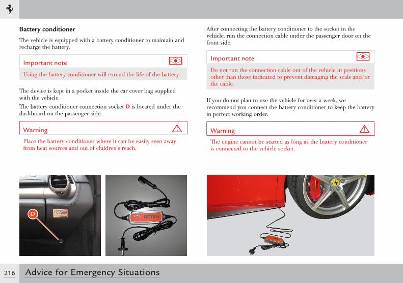
216 Advice for Emergency Situations
After connecting the battery conditioner to the socket in the vehicle, run the connection cable under the passenger door on the front side.
Important note
Do not run the connection cable out of the vehicle in positions other than those indicated to prevent damaging the seals and/or the cable.
If you do not plan to use the vehicle for over a week, we recommend you connect the battery conditioner to keep the battery in perfect working order.
Warning
The engine cannot be started as long as the battery conditioner is connected to the vehicle socket.
Battery conditioner
The vehicle is equipped with a battery conditioner to maintain and recharge the battery.
Important note
Using the battery conditioner will extend the life of the battery.
The device is kept in a pocket inside the car cover bag supplied with the vehicle.The battery conditioner connection socket D is located under the dashboard on the passenger side.
Warning
Place the battery conditioner where it can be easily seen away from heat sources and out of children's reach.
D
217
5
Advice for Emergency Situations
Important note
Additional technical information on the use of the device can be found in the manual provided inside the pocket of the car cover bag.
Exhaust system overheating alarm devices (“Slow Down” function)
If the engine is running unevenly resulting in exhaust system overheating, the “Slow Down” function is activated: a special symbol (see page 118) appears on the left TFT display accompanied by a message.The message varies according to three alarm levels:• Temperature high: “Catalysts temp. high. Slow down”.• Temperature too high: “Catalysts temp. too high. Engine
performance limited”.• Catalytic converter temperature system failure: “Catalysts temp.
not plausible. Go to dealer slowly”.
Displaying of the message is controlled by the thermistor via the engine control ECU.
Warning
Incorrect use of the vehicle may cause the “Slow Down” function to be activated.
Warning
If the temperature is high:slow down immediately so that the exhaust system temperature decreases.
218 Advice for Emergency Situations
Clutch overheat alarm devices
Extremely high performance use of the vehicle at high engine speeds for prolonged periods and at high ambient temperatures may cause the DCT gearbox clutches to overheat. In this case, the following safety warnings will be displayed on the left TFT display, corresponding to two different alarm levels:• The message “Clutch overheated”• The message “Clutch overheated” accompanied by an acoustic
signal.When the message “Clutch overheated” is displayed, the driver may notice a difference in the behaviour of the system during gearshifts and/or during standing starts.
Warning
If the temperature is too high: the temperature in the catalytic converters has reached a dangerous level and could damage them; if you continue to drive, the engine control ECU intervenes and reduces the torque produced by the engine.The torque limit remains active until the catalytic converter temperature goes down to normal operating values.
Warning
If catalytic converter temperature system failure information is displayed:- the engine control ECU intervenes and reduces the torque
produced by the engine- the driver must slow down and slowly drive to the nearest
Ferrari Service Network to have the engine parameters checked.
Warning
If the EOBD warning light (see page 117) comes on at the same time as the “Slow Down” message, go to the nearest Ferrari Service Network to have the ECU error memory checked. Do not proceed in any other way.
Clutchoverheated
219
5
Advice for Emergency Situations
Important note
Certain high-performance actions (including but not limited to: “LAUNCH” control start, standing start with wheelspin with Manettino set to ESC OFF, etc.) may be inhibited to prevent excessive overheating of the clutches: the system warns the driver that the action is not permitted by displaying the message “Operation not admissible” on the left TFT display.
Warning
As soon as any of the warnings described above appear on the left TFT display, the driver must slow down, continue driving at an engine speed between 2000 and 3000 rpm and minimise gearshift frequency to allow the clutches to cool down as quickly as possible. These driving conditions must be maintained until the message “Clutch overheated” is no longer displayed.
Engine malfunction alarm devices
If the “engine control system failure ” (EOBD, see page 117) warning light flashes or comes on permanently while the engine is running, it indicates that the engine or the emission control system may be malfunctioning.The electronic system detects and isolates the error preventing damage to the engine or the production of harmful emissions.
Warning
When the “engine diagnostic system failure” warning light comes on, engine performance may be considerably reduced.Drive carefully, avoiding sudden acceleration and high speeds.Contact the Ferrari Service Network immediately.
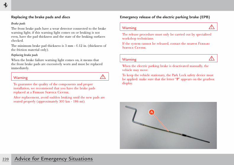
220 Advice for Emergency Situations
Emergency release of the electric parking brake (EPB)
Warning
The release procedure must only be carried out by specialised workshop technicians. If the system cannot be released, contact the nearest Ferrari Service Centre.
Warning
When the electric parking brake is deactivated manually, the vehicle may move.To keep the vehicle stationary, the Park Lock safety device must be applied: make sure that the letter “P” appears on the gearbox display.
A
Replacing the brake pads and discs
Brake pads
The front brake pads have a wear detector connected to the brake warning light; if this warning light comes on or braking is not even, have the pad thickness and the state of the braking surfaces checked.The minimum brake pad thickness is 3 mm - 0.12 in. (thickness of the friction material only).Replacing brake pads
When the brake failure warning light comes on, it means that the front brake pads are excessively worn and must be replaced immediately.
Warning
To guarantee the quality of the components and proper installation, we recommend that you have the brake pads replaced at a Ferrari Service Centre.After replacement, avoid sudden braking until the new pads are seated properly (approximately 300 km - 186 mi).
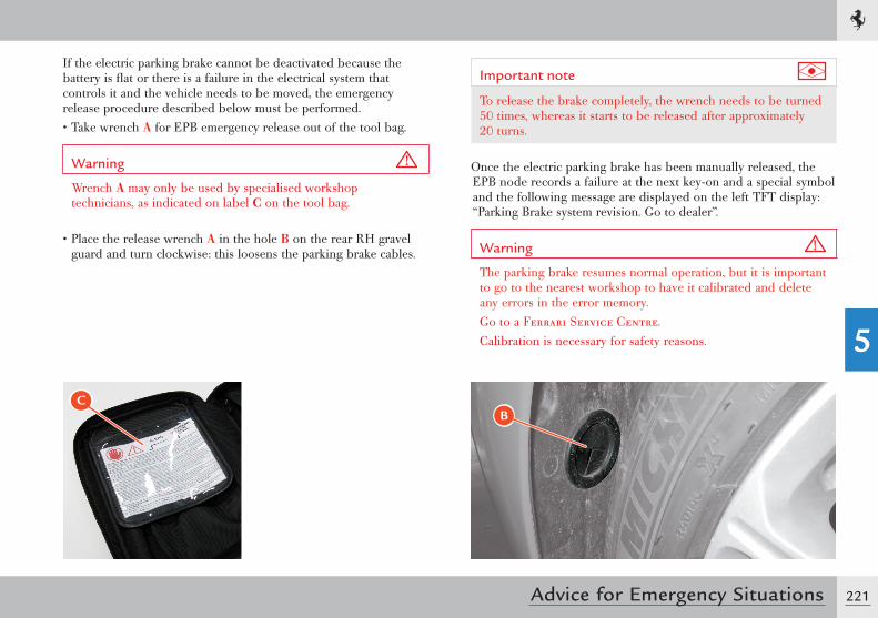
221
5
Advice for Emergency Situations
Important note
To release the brake completely, the wrench needs to be turned 50 times, whereas it starts to be released after approximately 20 turns.
Once the electric parking brake has been manually released, the EPB node records a failure at the next key-on and a special symbol and the following message are displayed on the left TFT display: “Parking Brake system revision. Go to dealer”.
Warning
The parking brake resumes normal operation, but it is important to go to the nearest workshop to have it calibrated and delete any errors in the error memory.Go to a Ferrari Service Centre.Calibration is necessary for safety reasons.
B
If the electric parking brake cannot be deactivated because the battery is flat or there is a failure in the electrical system that controls it and the vehicle needs to be moved, the emergency release procedure described below must be performed.• Take wrench A for EPB emergency release out of the tool bag.
Warning
Wrench A may only be used by specialised workshop technicians, as indicated on label C on the tool bag.
• Place the release wrench A in the hole B on the rear RH gravel guard and turn clockwise: this loosens the parking brake cables.
C
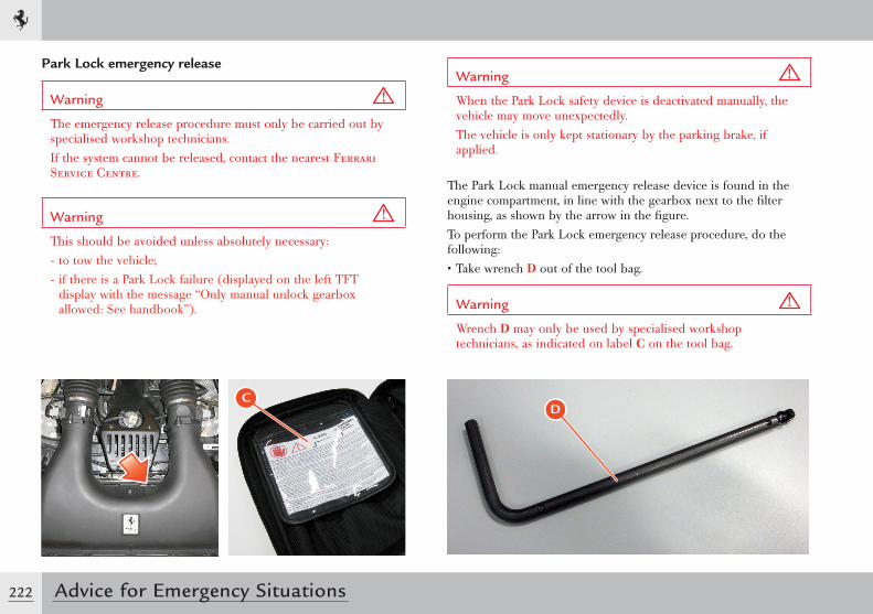
222 Advice for Emergency Situations
Park Lock emergency release
Warning
The emergency release procedure must only be carried out by specialised workshop technicians. If the system cannot be released, contact the nearest Ferrari Service Centre.
Warning
This should be avoided unless absolutely necessary:- to tow the vehicle;- if there is a Park Lock failure (displayed on the left TFT
display with the message “Only manual unlock gearbox allowed: See handbook”).
Warning
When the Park Lock safety device is deactivated manually, the vehicle may move unexpectedly.The vehicle is only kept stationary by the parking brake, if applied.
The Park Lock manual emergency release device is found in the engine compartment, in line with the gearbox next to the filter housing, as shown by the arrow in the figure.To perform the Park Lock emergency release procedure, do the following:• Take wrench D out of the tool bag.
Warning
Wrench D may only be used by specialised workshop technicians, as indicated on label C on the tool bag.
DC
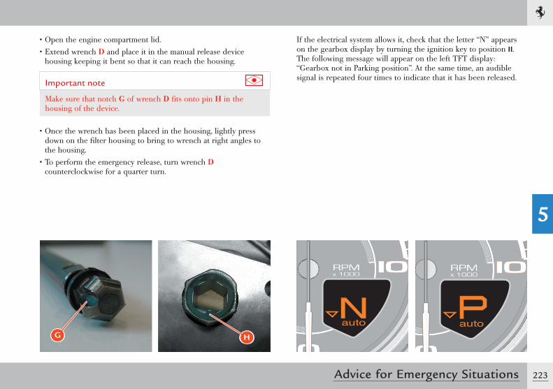
223
5
Advice for Emergency Situations
• Open the engine compartment lid.• Extend wrench D and place it in the manual release device
housing keeping it bent so that it can reach the housing.
Important note
Make sure that notch G of wrench D fi ts onto pin H in the housing of the device.
• Once the wrench has been placed in the housing, lightly press down on the fi lter housing to bring to wrench at right angles to the housing.
• To perform the emergency release, turn wrench D counterclockwise for a quarter turn.
G
If the electrical system allows it, check that the letter “N” appears on the gearbox display by turning the ignition key to position II. The following message will appear on the left TFT display: “Gearbox not in Parking position”. At the same time, an audible signal is repeated four times to indicate that it has been released.
H
Warranty Booklet ................................................ 226Maintenance ....................................................... 226Level checks ......................................................... 228Wheels and tyres ................................................. 235Maintenance of the seat belts and pretensioners ... 237Cleaning the vehicle ............................................. 237If the vehicle is stored for long periods .................. 241
CARE OF THE VEHICLE
6
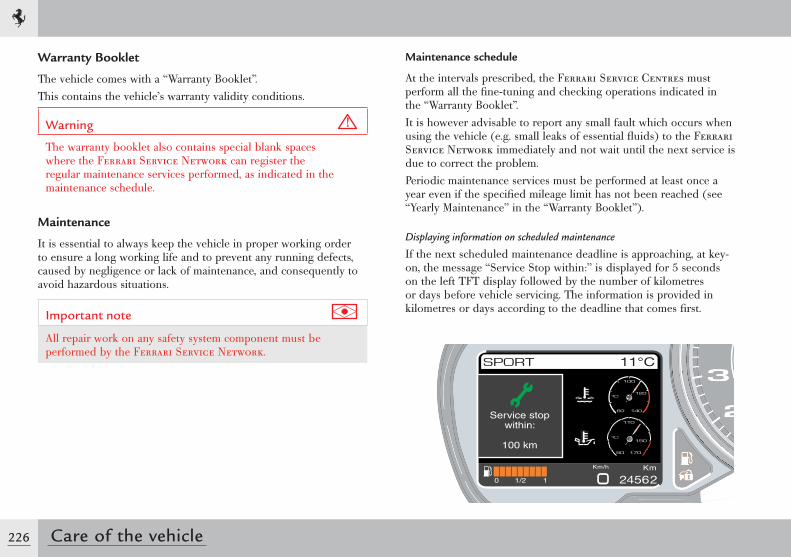
226 Care of the vehicle
Warranty Booklet
The vehicle comes with a “Warranty Booklet”.This contains the vehicle’s warranty validity conditions.
Warning
The warranty booklet also contains special blank spaces where the Ferrari Service Network can register the regular maintenance services performed, as indicated in the maintenance schedule.
Maintenance
It is essential to always keep the vehicle in proper working order to ensure a long working life and to prevent any running defects, caused by negligence or lack of maintenance, and consequently to avoid hazardous situations.
Important note
All repair work on any safety system component must be performed by the Ferrari Service Network.
Maintenance schedule
At the intervals prescribed, the Ferrari Service Centres must perform all the fi ne-tuning and checking operations indicated in the “Warranty Booklet”.It is however advisable to report any small fault which occurs when using the vehicle (e.g. small leaks of essential fl uids) to the Ferrari Service Network immediately and not wait until the next service is due to correct the problem.Periodic maintenance services must be performed at least once a year even if the specifi ed mileage limit has not been reached (see “Yearly Maintenance” in the “Warranty Booklet”).
Displaying information on scheduled maintenance
If the next scheduled maintenance deadline is approaching, at key-on, the message “Service Stop within:” is displayed for 5 seconds on the left TFT display followed by the number of kilometres or days before vehicle servicing. The information is provided in kilometres or days according to the deadline that comes fi rst.
Service stopwithin:
100 km
227
6
Care of the vehicle
Information on scheduled maintenance can also be displayed on the left TFT display if requested by the driver irrespective of the scheduled deadlines. To do this, call up the MENU screen page (see page 98) and select “Service”.Chassis and bodywork maintenanceThe chassis has technological and manufacturing specifications that require that any operation be performed by staff specially trained to work with this innovative technology.It is of crucial importance to use equipment tested by Ferrari if the repair work is to be performed in accordance with rules of good workmanship. Proper execution of repair work ensures that the commercial value of the vehicle is preserved and the safety standards are complied with.
Important note
If the chassis is damaged in an accident, Ferrari advises customers to contact the Ferrari Service Network who will perform the necessary safety checks.
The chassis, under standard conditions of use, requires no maintenance; it is however advisable to contact the Ferrari Service Network at the intervals indicated in the “Warranty Booklet“ in order to have it checked.
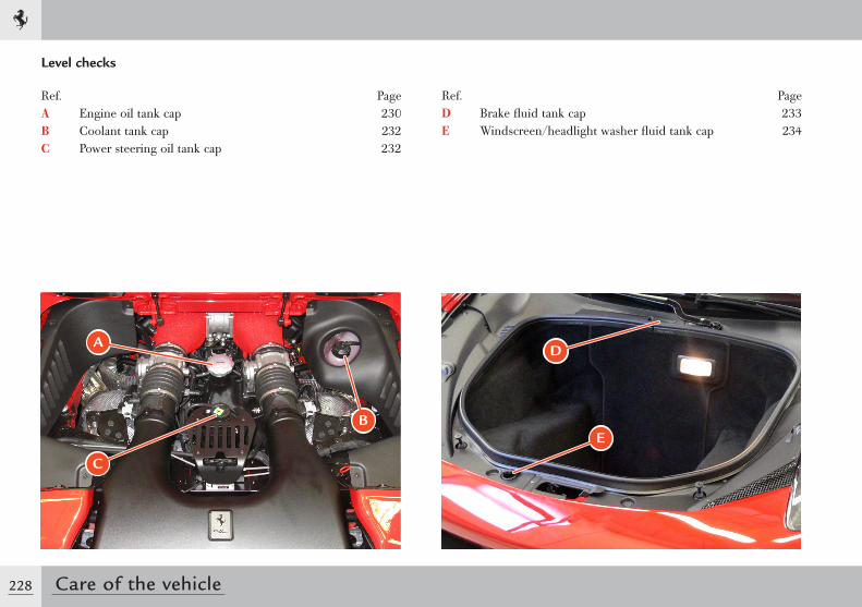
228 Care of the vehicle
Level checks
A
C
B
D
E
Ref. PageA Engine oil tank cap 230B Coolant tank cap 232C Power steering oil tank cap 232
Ref. PageD Brake fluid tank cap 233E Windscreen/headlight washer fluid tank cap 234
229
6
Care of the vehicle
Important note
The level checks must be performed at the intervals indicated in the “Warranty Booklet” or, in any case, before starting a long journey.
Environment
All the materials used for the following operations (e.g. cloths soaked with oil or grease, pans, etc.) must be disposed of in compliance with the environmental protection regulations.
Important note
Only use lubricants and/or fluids recommended by Ferrari (see the “Refilling” table on page 31).
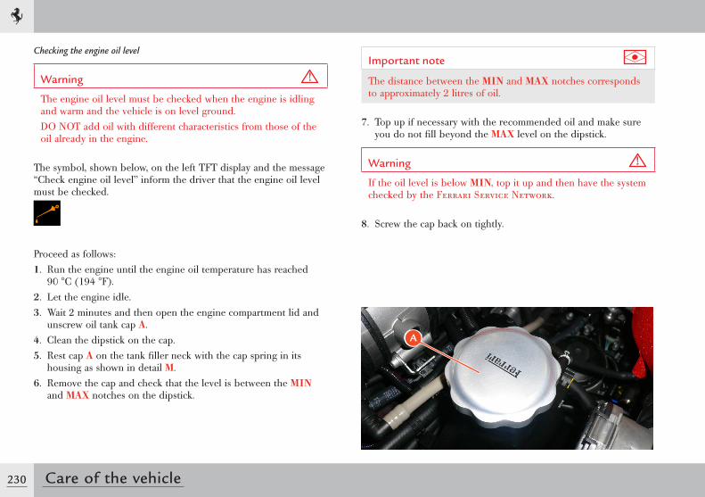
230 Care of the vehicle
Important note
The distance between the MIN and MAX notches corresponds to approximately 2 litres of oil.
7. Top up if necessary with the recommended oil and make sure you do not fill beyond the MAX level on the dipstick.
Warning
If the oil level is below MIN, top it up and then have the system checked by the Ferrari Service Network.
8. Screw the cap back on tightly.
A
Checking the engine oil level
Warning
The engine oil level must be checked when the engine is idling and warm and the vehicle is on level ground.DO NOT add oil with different characteristics from those of the oil already in the engine.
The symbol, shown below, on the left TFT display and the message “Check engine oil level” inform the driver that the engine oil level must be checked.
Proceed as follows:1. Run the engine until the engine oil temperature has reached
90 °C (194 °F).2. Let the engine idle.3. Wait 2 minutes and then open the engine compartment lid and
unscrew oil tank cap A.4. Clean the dipstick on the cap.5. Rest cap A on the tank filler neck with the cap spring in its
housing as shown in detail M.6. Remove the cap and check that the level is between the MIN
and MAX notches on the dipstick.
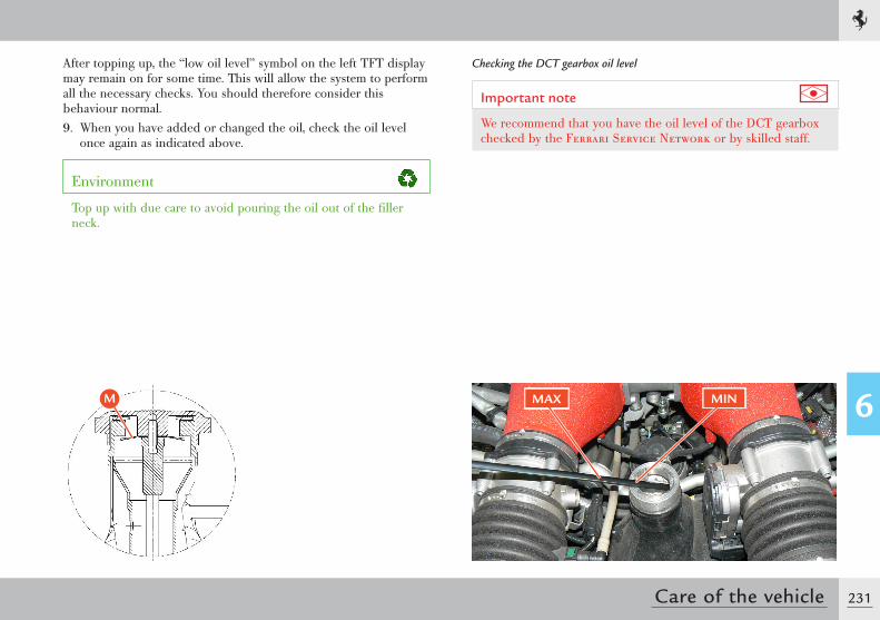
231
6
Care of the vehicle
After topping up, the “low oil level” symbol on the left TFT display may remain on for some time. This will allow the system to perform all the necessary checks. You should therefore consider this behaviour normal.9. When you have added or changed the oil, check the oil level
once again as indicated above.
Environment
Top up with due care to avoid pouring the oil out of the filler neck.
Checking the DCT gearbox oil level
Important note
We recommend that you have the oil level of the DCT gearbox checked by the Ferrari Service Network or by skilled staff.
MAX MINM
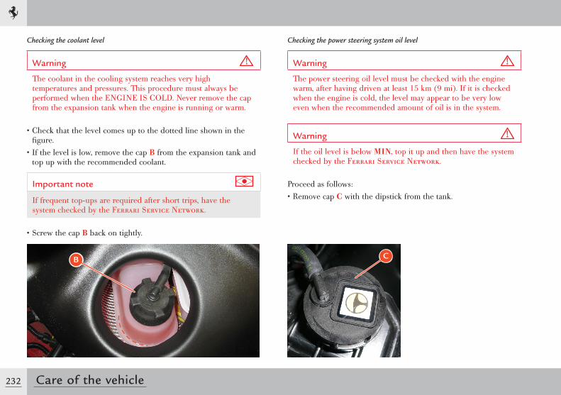
232 Care of the vehicle
Checking the coolant level
Warning
The coolant in the cooling system reaches very high temperatures and pressures. This procedure must always be performed when the ENGINE IS COLD. Never remove the cap from the expansion tank when the engine is running or warm.
• Check that the level comes up to the dotted line shown in the figure.
• If the level is low, remove the cap B from the expansion tank and top up with the recommended coolant.
Important note
If frequent top-ups are required after short trips, have the system checked by the Ferrari Service Network.
• Screw the cap B back on tightly.
B
Checking the power steering system oil level
Warning
The power steering oil level must be checked with the engine warm, after having driven at least 15 km (9 mi). If it is checked when the engine is cold, the level may appear to be very low even when the recommended amount of oil is in the system.
Warning
If the oil level is below MIN, top it up and then have the system checked by the Ferrari Service Network.
Proceed as follows:• Remove cap C with the dipstick from the tank.
C
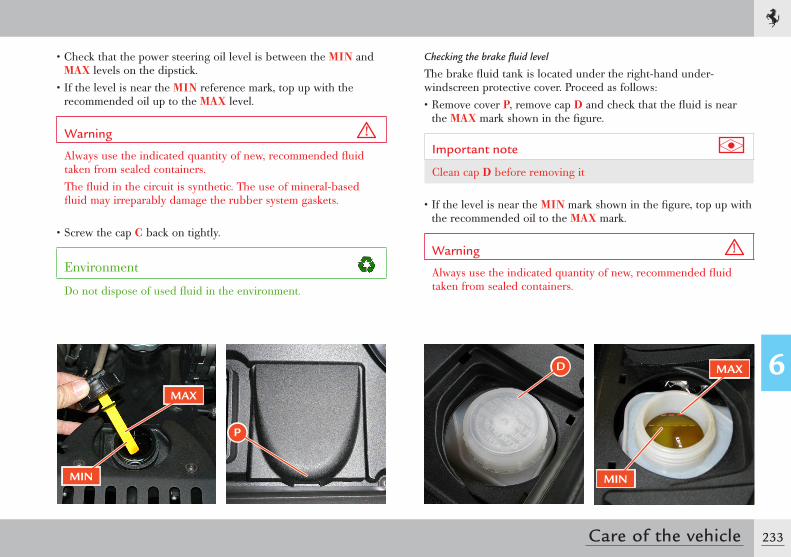
233
6
Care of the vehicle
• Check that the power steering oil level is between the MIN and MAX levels on the dipstick.
• If the level is near the MIN reference mark, top up with the recommended oil up to the MAX level.
Warning
Always use the indicated quantity of new, recommended fluid taken from sealed containers.The fluid in the circuit is synthetic. The use of mineral-based fluid may irreparably damage the rubber system gaskets.
• Screw the cap C back on tightly.
Environment
Do not dispose of used fluid in the environment.
MAX
MIN
Checking the brake fluid level
The brake fluid tank is located under the right-hand under-windscreen protective cover. Proceed as follows:• Remove cover P, remove cap D and check that the fluid is near
the MAX mark shown in the figure.
Important note
Clean cap D before removing it
• If the level is near the MIN mark shown in the figure, top up with the recommended oil to the MAX mark.
Warning
Always use the indicated quantity of new, recommended fluid taken from sealed containers.
P
D
MIN
MAX
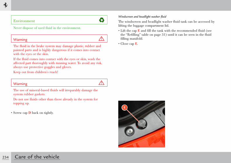
234 Care of the vehicle
Environment
Never dispose of used fluid in the environment.
Warning
The fluid in the brake system may damage plastic, rubber and painted parts and is highly dangerous if it comes into contact with the eyes or the skin.If the fluid comes into contact with the eyes or skin, wash the affected part thoroughly with running water. To avoid any risk, always use protective goggles and gloves.Keep out from children's reach!
Warning
The use of mineral-based fluids will irreparably damage the system rubber gaskets.Do not use fluids other than those already in the system for topping up.
• Screw cap D back on tightly.
Windscreen and headlight washer fluid
The windscreen and headlight washer fluid tank can be accessed by lifting the luggage compartment lid.• Lift the cap E and fill the tank with the recommended fluid (see
the “Refilling” table on page 31) until it can be seen in the fluid filling manifold.
• Close cap E.
E
235
6
Care of the vehicle
Wheels and tyres
To ensure maximum performance and tyre life and to permit the best tyre adjustment on the wheel rim, it is important to comply with the following instructions for the first 200/300 km (125 - 185 mi) with new tyres:• avoid sudden acceleration• avoid sharp braking and steering• drive at moderate speed on straight roads and on curves.
How to use the tyres
Important note
To ensure safe driving, the tyres must be kept in good condition.
The inflation pressure must correspond to the specified values and must be checked only when the tyres are cold since tyre pressure increases as tyre temperature increases.Never reduce the pressure if the tyres are hot.
Environment
Periodically check the tyre pressure. Driving with the tyres inflated to the correct pressure helps to reduce fuel consumption.
Low tyre pressure can lead to overheating, internal damage and even destruction of the tyres.
Warning
Inflating the tyres to a pressure other than that prescribed will render the TPMS monitoring system (if present) inaccurate.
Sudden impact with pavements, potholes and other obstacles of various types as well as long trips on rough roads can cause damage to the tyres that is not always visible to the naked eye.Check the tyres regularly for any signs of damage (e.g. scratches, cuts, cracks, bulges, etc.).If sharp objects penetrate the tyres, they can cause damage which is only visible when the tyre is removed.Have any damage inspected by an expert as it may considerably reduce tyre life.Remember that tyres deteriorate over time even if they are rarely used or not used at all.Cracks in the tread and side walls, possibly accompanied by bulging, are sure signs of ageing.
236 Care of the vehicle
Warning
The Ferrari Service Network has the necessary equipment for tyre replacement.Have the tyres replaced by the Ferrari Service Network that has the necessary equipment available to avoid causing damage through carelessness to the sensor located inside the wheel rim (on vehicles with the tyre temperature and pressure monitoring system - TPMS).Ensure that tyres are not kept in stock for more than 4 years. The maximum limit for keeping tyres in stock is 4 years provided they are kept away from sunlight, bad weather and damp and where there is a low oxygen content.
Important note
The Ferrari Service Network can certify whether aged tyres are suitable for use. In any case, tyres that have been on a vehicle for more than 3 years must be checked by a Ferrari Service Centre.
Warning
We recommend replacing tyres every 4 years under normal use. Frequent use in maximum load conditions and at high temperatures may accelerate ageing.
Never fit tyres of uncertain origin.
Warning
The tyres are of the “directional” type and there is an arrow marked on their side wall to indicate the direction in which they must rotate or which side is the outer side. When replaced, maximum performance levels can only be ensured if the rotation direction corresponds with the direction indicated by the arrow.Tyres on the same axle must always be replaced in pairs.
Regularly check the tyre tread (minimum acceptable depth 1.7 mm). As the tread wear increases, there is a greater risk of skidding.
Warning
Drive carefully on wet roads to reduce the risk of “aquaplaning”.
Wheel alignment check and adjustment
When you notice unusual wear of the tyres and in any case, at the intervals prescribed in the “Warranty Booklet”, have the Ferrari Service Network check the wheel toe-in and camber.
237
6
Care of the vehicle
Maintenance of seat belts and pretensioners
• Periodically check that the screws on the anchor points are tight and that the seat belt is in perfect condition and slides smoothly.
• The seat belt must be kept clean; the presence of any dirt could prevent the seat belt retractor from working properly.
• To clean the seat belt, wash it by hand with mild soap and water, rinse it and let it dry. Do not use strong detergents, bleach or aggressive solvents, as they can weaken the fibres.
• Do not let the seat belt retractors get wet: proper functioning is only ensured if they are kept dry.
• The pretensioner requires no maintenance or lubrication. If immersed in water or mud, the pretensioner must necessarily be replaced.
• The pretensioner must be replaced at the intervals indicated in the “Warranty Booklet”.
Cleaning the vehicle
Cleaning the exterior
Environment
All the materials used for the following operations (e.g. cloths soaked with oil or grease, pans, etc.) must be disposed of in compliance with the environmental protection regulations.
Proper care of the vehicle on the part of the owner is essential for the vehicle long life.Here is a list of the main precautions to be taken.• Certain parts of the vehicle should not be left wet or dirty for
long periods of time: in particular, the passenger compartment floor and the luggage compartment must always be kept clean and dry. The drain holes under the doors should be kept unclogged to allow any water to drain.
• The underbody and the lower surfaces of the vehicle should be cleaned regularly, and more frequently (at least once a week) if the vehicle is used on salty or rough roads. The vehicle should be cleaned thoroughly and carefully: cleaning that merely wets encrusted mud without removing it completely can prove damaging.
• The vehicle must be washed regularly with suitable equipment. Do not use very hot water or steam to clean the paintwork and the lower surfaces. It is advisable to soften any dirt first, then remove it with a jet of water at room temperature.
238 Care of the vehicle
Important note
Do not use aggressive products for cleaning the windows.The use of aggressive products could seriously damage the bodywork.
• Do not wash the vehicle in direct sunlight or when the bodywork is still warm: make sure that the jet of water does not blast the paintwork; wash the vehicle with a sponge and a mild soap and water solution; rinse the vehicle again with a jet of water and dry it with a chamois leather.
Important note
When the vehicle has been washed, apply slight pressure to the brake pedal at moderate speed before driving at a normal speed, until the brake discs and pads have cleaned off.
In order to maintain the shine on the paintwork, polish it once or twice a year with products recommended by Ferrari.• Any areas that are cracked or chipped by stones, scratches or
parking manoeuvres, etc., must be immediately repaired by the Ferrari Service Network.
• Do not park the vehicle in damp and/or unventilated areas for long periods of time.
Cleaning and care of matt paintwork (optional)
Warning
The paintwork MUST NOT be polished using any type of product.
Owners must take great care of vehicles with matt paintwork (optional).Here is a list of the main precautions to be taken.• Wash the vehicle using a steam cleaner and rinse with
demineralised water only.• It must be dried using an automatic dryer or compressed air.
Manual drying can ONLY be performed using a clean 3M microfibre yellow cloth that has been soaked in demineralised water in the areas where limescale deposits are present. The cloth must be kept in a special clean container.
• To clean any grease or oil marks, a clean 3M microfibre yellow cloth soaked in R107/S solvent (heptane) can be used. A new cloth must be used and it must not have been previously soaked in demineralised water.
• Do not wash the car in direct sunlight.• Wash the vehicle only when the bodywork and engine are cold.• Do not apply stickers to the bodywork.
239
6
Care of the vehicle
• Any areas that are cracked or chipped by stones, scratches or parking manoeuvres, etc., must be immediately repaired by the Ferrari Service Network.
Important note
DO NOT lean against the vehicle especially if you are wearing clothes with buttons, buckles or are wearing rings, necklaces, etc. This may cause irreparable damage to the bodywork.
Important note
To use suitable products, contact the Ferrari Service Network.
Cleaning of protective antistone-chipping film (optional)
The film has been designed to protect the bodywork: anything that damages the paint will also damage the film.
Warning
Do not pour denatured ethyl alcohol, acetone, isopropyl alcohol, heptane or substances that contain these compounds on the film.
• Do not apply adhesive elements on the film.• When cleaning, do not use metal or abrasive substances in general
and acid chemical compounds.
Important note
Avoid the film coming into contact with the brake fluid: the film will become opaque.
• Do not use solvents along the edges of the film to them from penetrating inside the adhesive layer.
Important note
Nürburgring Silver, Avus White, Alloy Grey, Met Avio, Ivory, Met Light Blue, Met Sky-Blue and Fuji White vehicles must be washed every month and waxed at least twice a year so that dirt, acid rain, pollutants, etc. do not penetrate the pores of the film and cause it to tarnish.
Important note
We recommend that the film be replaced every 24 months for Nürburgring Silver, Avus White, Alloy Grey, Met Avio, Ivory, Met Light Blue, Met Sky-Blue and Fuji White vehicles, which may show a light visible tarnish due to dirt inside the pores of the film.
It should be noted that timely and accurate cleaning (monthly washing and waxing twice a year at least) will prevent deterioration of the film.
240 Care of the vehicle
Cleaning the interior
Cleaning and care of the leather upholstery
As indicated in the “Maintenance Schedule” (see the “Warranty Booklet”), proper and regular treatment, at least once a year, will help preserve the quality, natural characteristics and softness of the leather upholstery in your Ferrari.With this in mind, specific leather care products are also available (“Cleaner” and “Cream”) both tested by Ferrari.These products can be ordered through the Ferrari Spare Parts Service Department, both individually and as part of the “Care Kit” which includes the complete range of products for cleaning the vehicle.
Important note
For use of the “Care Kit” products, contact the Ferrari Service Network.
The following products must be avoided when cleaning the leather: harsh detergents, turpentine, liquid stain removers, petrol, solvents and domestic cleaning products. All of these products damage the natural material.
Cleaning and care of the Alcantara® upholstery
Warning
Do not use steam cleaners.
• Carefully dust the parts to be cleaned• Use a soft cloth or sponge moistened with clean water• Thoroughly wring out the cloth and wipe it over the entire
Alcantara® area making sure you do not overwet it• Repeat the procedure• Let it dry completely• To recondition the material, gently use a brush with soft bristles.
241
6
Care of the vehicle
If the vehicle is stored for long periodsIf the vehicle is not used for long periods of time, certain precautions should be taken:• if possible, park the vehicle on a level surface in a covered and
well-ventilated area• prevent the vehicle from moving by engaging a gear• bring the tyre pressure to 3.0 bar (43.51 psi) and periodically
change the point where the tyres rest on the ground• connect the battery conditioner
Important note
If you do not want to connect the battery to the battery conditioner in order to keep certain devices functioning such as radio station memory, alarm system, etc., the battery must be recharged at least once a month. If the vehicle is not used for long periods of time without connecting the battery conditioner, the battery must be recharged at least every three months.
• protect the vehicle with a breathable fabric cover and avoid materials that prevent any dampness on the bodywork from evaporating.
Before using the vehicle again after long periods of inactivity, adjust the tyre pressure to the indicated pressure and check the fluid levels of all the systems.

Glossary .............................................................. 245
GLOSSARY
7

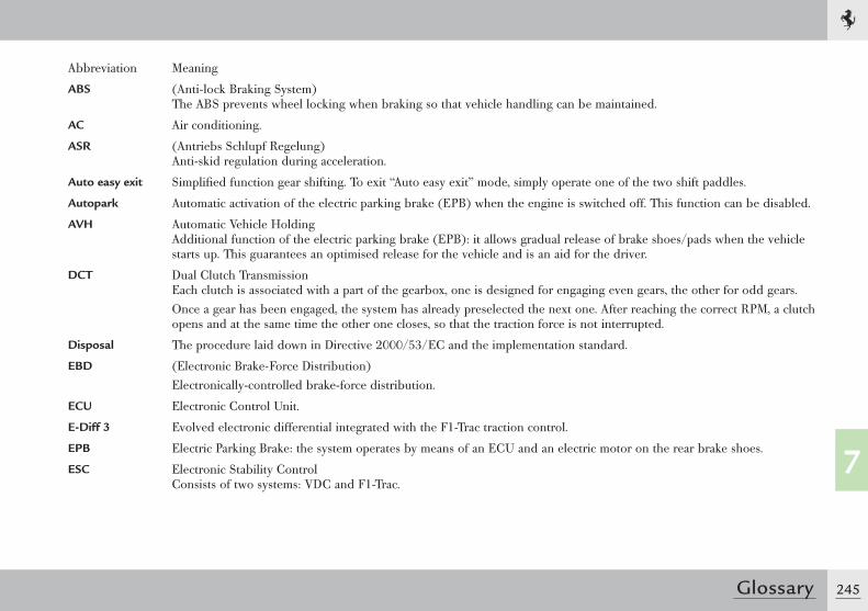
245
7
Glossary
Abbreviation Meaning
ABS (Anti-lock Braking System) The ABS prevents wheel locking when braking so that vehicle handling can be maintained.
AC Air conditioning.
ASR (Antriebs Schlupf Regelung) Anti-skid regulation during acceleration.
Auto easy exit Simplified function gear shifting. To exit “Auto easy exit” mode, simply operate one of the two shift paddles.
Autopark Automatic activation of the electric parking brake (EPB) when the engine is switched off. This function can be disabled.
AVH Automatic Vehicle Holding Additional function of the electric parking brake (EPB): it allows gradual release of brake shoes/pads when the vehicle starts up. This guarantees an optimised release for the vehicle and is an aid for the driver.
DCT Dual Clutch Transmission Each clutch is associated with a part of the gearbox, one is designed for engaging even gears, the other for odd gears.Once a gear has been engaged, the system has already preselected the next one. After reaching the correct RPM, a clutch opens and at the same time the other one closes, so that the traction force is not interrupted.
Disposal The procedure laid down in Directive 2000/53/EC and the implementation standard.
EBD (Electronic Brake-Force Distribution)Electronically-controlled brake-force distribution.
ECU Electronic Control Unit.
E-Diff 3 Evolved electronic differential integrated with the F1-Trac traction control.
EPB Electric Parking Brake: the system operates by means of an ECU and an electric motor on the rear brake shoes.
ESC Electronic Stability Control Consists of two systems: VDC and F1-Trac.
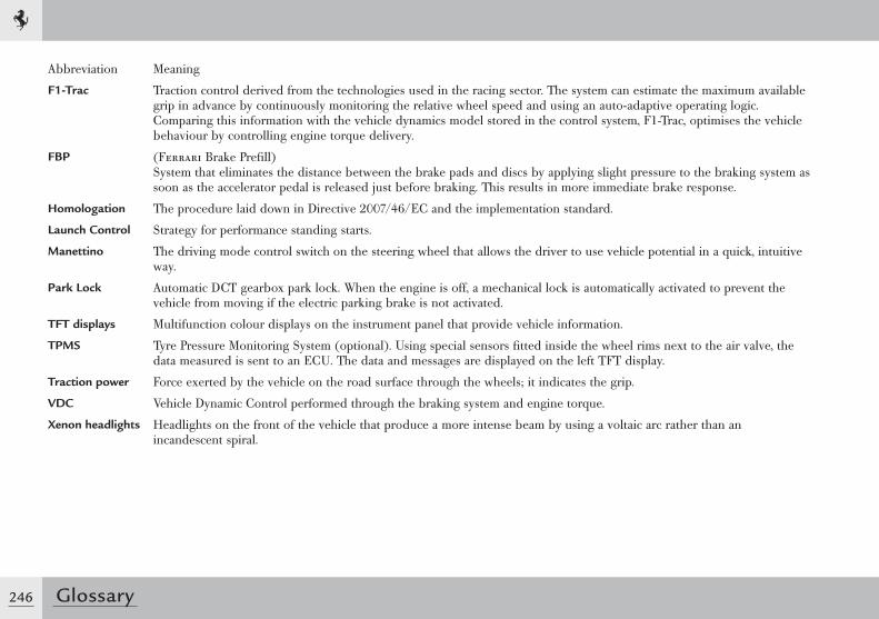
246 Glossary
Abbreviation Meaning
F1-Trac Traction control derived from the technologies used in the racing sector. The system can estimate the maximum available grip in advance by continuously monitoring the relative wheel speed and using an auto-adaptive operating logic. Comparing this information with the vehicle dynamics model stored in the control system, F1-Trac, optimises the vehicle behaviour by controlling engine torque delivery.
FBP (Ferrari Brake Prefill) System that eliminates the distance between the brake pads and discs by applying slight pressure to the braking system as soon as the accelerator pedal is released just before braking. This results in more immediate brake response.
Homologation The procedure laid down in Directive 2007/46/EC and the implementation standard.
Launch Control Strategy for performance standing starts.
Manettino The driving mode control switch on the steering wheel that allows the driver to use vehicle potential in a quick, intuitive way.
Park Lock Automatic DCT gearbox park lock. When the engine is off, a mechanical lock is automatically activated to prevent the vehicle from moving if the electric parking brake is not activated.
TFT displays Multifunction colour displays on the instrument panel that provide vehicle information.
TPMS Tyre Pressure Monitoring System (optional). Using special sensors fitted inside the wheel rims next to the air valve, the data measured is sent to an ECU. The data and messages are displayed on the left TFT display.
Traction power Force exerted by the vehicle on the road surface through the wheels; it indicates the grip.
VDC Vehicle Dynamic Control performed through the braking system and engine torque.
Xenon headlights Headlights on the front of the vehicle that produce a more intense beam by using a voltaic arc rather than an incandescent spiral.

247
7
Glossary

Table of Contents ................................................ 250
TABLE OF CONTENTS
8
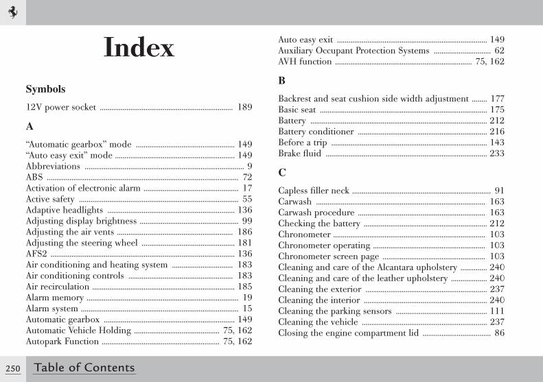
250 Table of Contents
IndexSymbols
12V power socket ...................................................................... 189
A
“Automatic gearbox” mode .................................................... 149“Auto easy exit” mode ............................................................... 149Abbreviations .................................................................................... 9ABS ..................................................................................................... 72Activation of electronic alarm .................................................. 17Active safety .................................................................................... 55Adaptive headlights ................................................................... 136Adjusting display brightness .................................................... 99Adjusting the air vents ............................................................. 186Adjusting the steering wheel ................................................. 181AFS2 ................................................................................................. 136Air conditioning and heating system ................................ 183Air conditioning controls ....................................................... 183Air recirculation ........................................................................... 185Alarm memory ................................................................................ 19Alarm system ................................................................................... 15Automatic gearbox ..................................................................... 149Automatic Vehicle Holding ............................................. 75, 162Autopark Function .............................................................. 75, 162
Auto easy exit ............................................................................... 149Auxiliary Occupant Protection Systems .............................. 62AVH function ........................................................................ 75, 162
B
Backrest and seat cushion side width adjustment ........ 177Basic seat ........................................................................................ 175Battery ............................................................................................. 212Battery conditioner .................................................................... 216Before a trip .................................................................................. 143Brake fluid ..................................................................................... 233
C
Capless filler neck ......................................................................... 91Carwash ......................................................................................... 163Carwash procedure ................................................................... 163Checking the battery ................................................................. 212Chronometer ................................................................................ 103Chronometer operating ........................................................... 103Chronometer screen page ...................................................... 103Cleaning and care of the Alcantara upholstery .............. 240Cleaning and care of the leather upholstery ................... 240Cleaning the exterior ................................................................ 237Cleaning the interior ................................................................. 240Cleaning the parking sensors ................................................ 111Cleaning the vehicle .................................................................. 237Closing the engine compartment lid .................................... 86
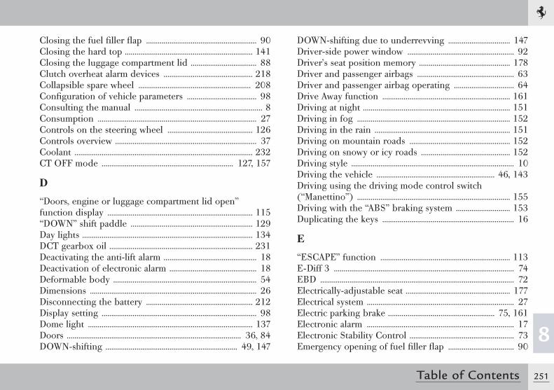
251
8
Table of Contents
Closing the fuel filler flap ......................................................... 90Closing the hard top .................................................................. 141Closing the luggage compartment lid .................................. 88Clutch overheat alarm devices .............................................. 218Collapsible spare wheel .......................................................... 208Configuration of vehicle parameters .................................... 98Consulting the manual .................................................................. 8Consumption .................................................................................. 27Controls on the steering wheel ............................................ 126Controls overview ......................................................................... 37Coolant ............................................................................................ 232CT OFF mode .................................................................... 127, 157
D
“Doors, engine or luggage compartment lid open” function display ........................................................................... 115“DOWN” shift paddle ............................................................... 129Day lights ........................................................................................ 134DCT gearbox oil .......................................................................... 231Deactivating the anti-lift alarm ................................................ 18Deactivation of electronic alarm ............................................. 18Deformable body .......................................................................... 54Dimensions ...................................................................................... 26Disconnecting the battery ....................................................... 212Display setting ................................................................................ 98Dome light ..................................................................................... 137Doors .......................................................................................... 36, 84DOWN-shifting .................................................................... 49, 147
DOWN-shifting due to underrevving ................................ 147Driver-side power window ....................................................... 92Driver’s seat position memory ............................................... 178Driver and passenger airbags .................................................. 63Driver and passenger airbag operating ............................... 64Drive Away function .................................................................. 161Driving at night ............................................................................ 151Driving in fog ............................................................................... 152Driving in the rain ...................................................................... 151Driving on mountain roads .................................................... 152Driving on snowy or icy roads .............................................. 152Driving style .................................................................................... 10Driving the vehicle ............................................................. 46, 143Driving using the driving mode control switch (“Manettino”) ............................................................................... 155Driving with the “ABS” braking system ............................ 153Duplicating the keys .................................................................... 16
E
“ESCAPE” function ................................................................... 113E-Diff 3 ............................................................................................. 74EBD .................................................................................................... 72Electrically-adjustable seat ...................................................... 177Electrical system ............................................................................ 27Electric parking brake ....................................................... 75, 161Electronic alarm ............................................................................ 17Electronic Stability Control ...................................................... 73Emergency opening of fuel filler flap .................................. 90
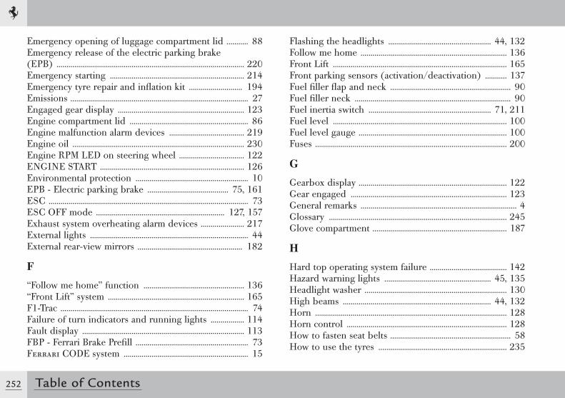
252 Table of Contents
Emergency opening of luggage compartment lid ........... 88Emergency release of the electric parking brake (EPB) ............................................................................................... 220Emergency starting .................................................................... 214Emergency tyre repair and inflation kit ........................... 194Emissions .......................................................................................... 27Engaged gear display ................................................................ 123Engine compartment lid ............................................................ 86Engine malfunction alarm devices ...................................... 219Engine oil ....................................................................................... 230Engine RPM LED on steering wheel ................................. 122ENGINE START ......................................................................... 126Environmental protection ......................................................... 10EPB - Electric parking brake ......................................... 75, 161ESC ..................................................................................................... 73ESC OFF mode ................................................................. 127, 157Exhaust system overheating alarm devices ...................... 217External lights ................................................................................ 44External rear-view mirrors ..................................................... 182
F
“Follow me home” function ................................................... 136“Front Lift” system ..................................................................... 165F1-Trac ............................................................................................... 74Failure of turn indicators and running lights ................. 114Fault display .................................................................................. 113FBP - Ferrari Brake Prefill ......................................................... 73Ferrari CODE system ............................................................... 15
Flashing the headlights .................................................... 44, 132Follow me home .......................................................................... 136Front Lift ........................................................................................ 165Front parking sensors (activation/deactivation) ........... 137Fuel filler flap and neck ............................................................. 90Fuel filler neck ............................................................................... 90Fuel inertia switch .............................................................. 71, 211Fuel level ........................................................................................ 100Fuel level gauge ........................................................................... 100Fuses ................................................................................................. 200
G
Gearbox display ........................................................................... 122Gear engaged ............................................................................... 123General remarks ............................................................................... 4Glossary .......................................................................................... 245Glove compartment .................................................................... 187
H
Hard top operating system failure ....................................... 142Hazard warning lights ...................................................... 45, 135Headlight washer ........................................................................ 130High beams ........................................................................... 44, 132Horn ................................................................................................. 128Horn control ................................................................................. 128How to fasten seat belts ............................................................. 58How to use the tyres ................................................................. 235
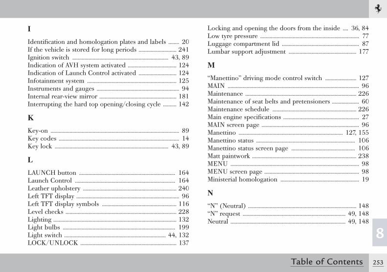
253
8
Table of Contents
I
Identification and homologation plates and labels ........ 20If the vehicle is stored for long periods ............................ 241Ignition switch ....................................................................... 43, 89Indication of AVH system activated .................................... 124Indication of Launch Control activated ............................ 124Infotainment system .................................................................. 125Instruments and gauges ............................................................. 94Internal rear-view mirror ......................................................... 181Interrupting the hard top opening/closing cycle .......... 142
K
Key-on ............................................................................................... 89Key codes ......................................................................................... 14Key lock .................................................................................... 43, 89
L
LAUNCH button ....................................................................... 164Launch Control .......................................................................... 164Leather upholstery ..................................................................... 240Left TFT display ............................................................................ 96Left TFT display symbols ....................................................... 116Level checks .................................................................................. 228Lighting ........................................................................................... 132Light bulbs ................................................................................... 199Light switch ........................................................................... 44, 132LOCK/UNLOCK ....................................................................... 137
Locking and opening the doors from the inside .... 36, 84Low tyre pressure ......................................................................... 77Luggage compartment lid ......................................................... 87Lumbar support adjustment .................................................. 177
M
“Manettino” driving mode control switch ....................... 127MAIN ................................................................................................. 96Maintenance .................................................................................. 226Maintenance of seat belts and pretensioners .................... 60Maintenance schedule .............................................................. 226Main engine specifications ........................................................ 27MAIN screen page ........................................................................ 96Manettino ............................................................................. 127, 155Manettino status ......................................................................... 106Manettino status screen page ............................................... 106Matt paintwork ............................................................................. 238MENU ............................................................................................... 98MENU screen page ...................................................................... 98Ministerial homologation .......................................................... 19
N
“N” (Neutral) ................................................................................ 148“N” request ............................................................................ 49, 148Neutral ..................................................................................... 49, 148
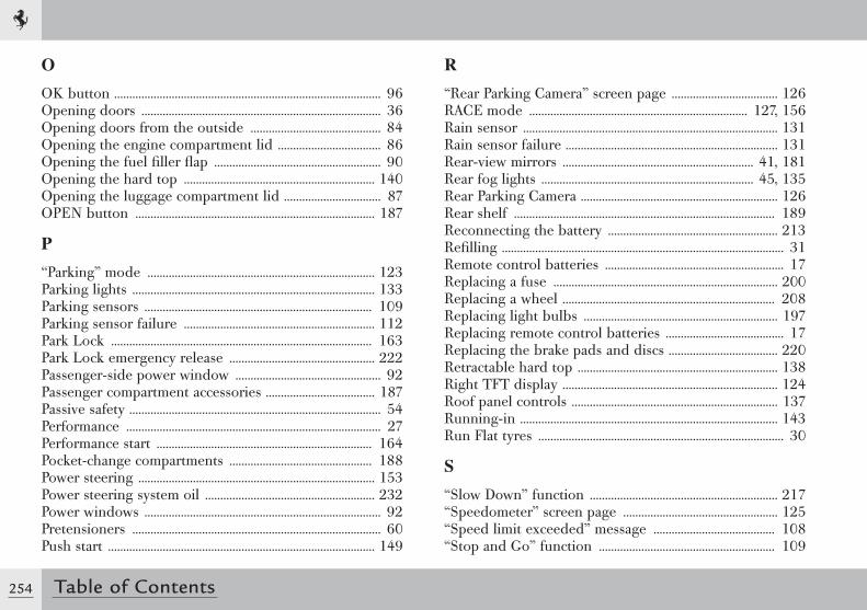
254 Table of Contents
O
OK button ........................................................................................ 96Opening doors ............................................................................... 36Opening doors from the outside ........................................... 84Opening the engine compartment lid .................................. 86Opening the fuel filler flap ....................................................... 90Opening the hard top ............................................................... 140Opening the luggage compartment lid ................................ 87OPEN button ............................................................................... 187
P
“Parking” mode ........................................................................... 123Parking lights ................................................................................ 133Parking sensors ........................................................................... 109Parking sensor failure ............................................................... 112Park Lock ...................................................................................... 163Park Lock emergency release ................................................ 222Passenger-side power window ................................................ 92Passenger compartment accessories .................................... 187Passive safety ................................................................................... 54Performance .................................................................................... 27Performance start ....................................................................... 164Pocket-change compartments ............................................... 188Power steering .............................................................................. 153Power steering system oil ........................................................ 232Power windows .............................................................................. 92Pretensioners .................................................................................. 60Push start ........................................................................................ 149
R
“Rear Parking Camera” screen page ................................... 126RACE mode ........................................................................ 127, 156Rain sensor .................................................................................... 131Rain sensor failure ...................................................................... 131Rear-view mirrors ............................................................... 41, 181Rear fog lights ...................................................................... 45, 135Rear Parking Camera ................................................................. 126Rear shelf ...................................................................................... 189Reconnecting the battery ........................................................ 213Refilling ............................................................................................. 31Remote control batteries ........................................................... 17Replacing a fuse .......................................................................... 200Replacing a wheel ...................................................................... 208Replacing light bulbs ................................................................ 197Replacing remote control batteries ....................................... 17Replacing the brake pads and discs .................................... 220Retractable hard top .................................................................. 138Right TFT display ....................................................................... 124Roof panel controls .................................................................... 137Running-in ..................................................................................... 143Run Flat tyres ................................................................................. 30
S
“Slow Down” function .............................................................. 217“Speedometer” screen page ................................................... 125“Speed limit exceeded” message ........................................ 108“Stop and Go” function .......................................................... 109
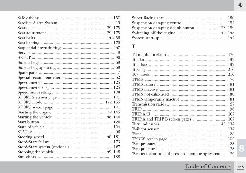
255
8
Table of Contents
Safe driving ................................................................................... 150Satellite Alarm System ................................................................ 19Seats ......................................................................................... 39, 175Seat adjustment ................................................................... 39, 175Seat belts ................................................................................... 42, 56Seat heating ................................................................................... 179Sequential downshifting .......................................................... 147Service .................................................................................................. 8SETUP ............................................................................................... 96Side airbags ..................................................................................... 68Side airbag operating .................................................................. 68Spare parts .......................................................................................... 7Special recommendations ......................................................... 52Speedometer ................................................................................. 125Speedometer display ................................................................. 125Speed limit setting ..................................................................... 108SPORT 2 screen page ............................................................... 101SPORT mode ..................................................................... 127, 155SPORT screen page ................................................................... 101Starting the engine .............................................................. 47, 145Starting the vehicle ............................................................ 48, 146Start button ................................................................................... 126State of vehicle ............................................................................ 104STATUS ............................................................................................. 96Steering wheel ..................................................................... 40, 181Stop&Start failure ....................................................................... 173Stop&Start system (optional) ................................................ 167Stopping the vehicle .......................................................... 49, 148Sun visors ...................................................................................... 188
Super Racing seat ...................................................................... 180Suspension damping control ................................................. 154Suspension damping delink button ......................... 128, 159Switching off the engine .................................................. 49, 148System start-up ............................................................................ 144
T
Tilting the backrest .................................................................... 176Toolkit ............................................................................................. 192Tool bag ......................................................................................... 192Towing ............................................................................................. 210Tow hook ........................................................................................ 210TPMS ................................................................................................. 76TPMS failure ................................................................................... 81TPMS inactive ................................................................................ 81TPMS not calibrated ................................................................... 80TPMS temporarily inactive ....................................................... 81Transmission ratios ....................................................................... 27TRIP ................................................................................................... 96TRIP A/B ....................................................................................... 107TRIP A and TRIP B screen pages ....................................... 107Turn indicators ..................................................................... 45, 134Twilight sensor ............................................................................. 134Tyres ................................................................................................... 28TYRES screen page .................................................................. 102Tyre pressure .................................................................................. 28Tyre puncture ................................................................................. 78Tyre temperature and pressure monitoring system ....... 76
256 Table of Contents
U
“UP” shift paddle ........................................................................ 129Unfastening the seat belts ......................................................... 59UP, DOWN, LEFT, RIGHT buttons ..................................... 96UP-shifting ............................................................................. 49, 147UP-shifting due to overrevving ............................................ 147Use of the vehicle ......................................................................... 10
V
VDA .......................................................................................... 96, 102Vehicle Dynamic Assistance ................................................... 102Vehicle keys ..................................................................................... 14Vehicle status screen page ...................................................... 104
W
“Warning: danger of ice” message ...................................... 108Warming up the engine .................................................... 48, 146Warning lights on the panel ................................................... 116Warranty Booklet ................................................................... 7, 226Weights .............................................................................................. 26WET mode .......................................................................... 127, 155Wheel alignment check and adjustment ........................... 236Wheel rims ....................................................................................... 28While travelling ............................................................................ 150Windscreen and headlight washer fluid ........................... 234Windscreen washer .................................................................... 130Windscreen washer/wiper ...................................................... 129
Windscreen washer/wiper lever ........................................... 129Winter tyres ..................................................................................... 28
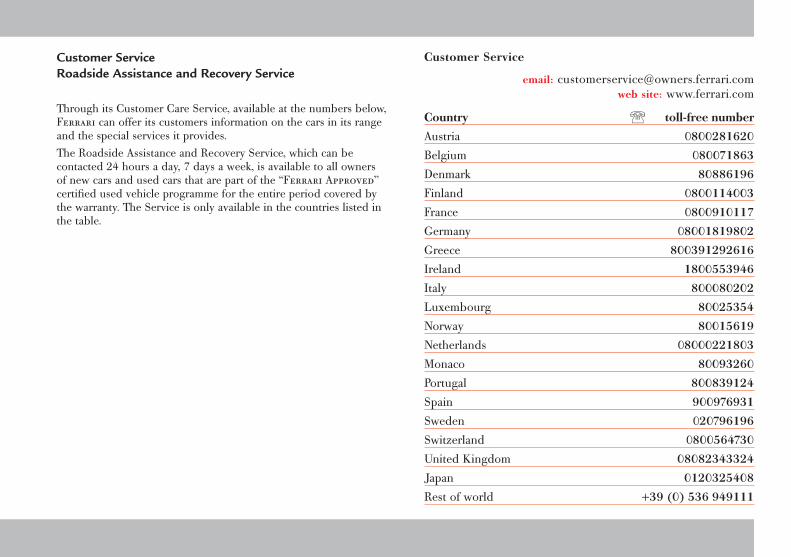
Customer Service Roadside Assistance and Recovery Service
Through its Customer Care Service, available at the numbers below, Ferrari can offer its customers information on the cars in its range and the special services it provides.The Roadside Assistance and Recovery Service, which can be contacted 24 hours a day, 7 days a week, is available to all owners of new cars and used cars that are part of the “Ferrari Approved” certified used vehicle programme for the entire period covered by the warranty. The Service is only available in the countries listed in the table.
Customer Service
email: [email protected] site: www.ferrari.com
Country toll-free number
Austria 0800281620
Belgium 080071863
Denmark 80886196
Finland 0800114003
France 0800910117
Germany 08001819802
Greece 800391292616
Ireland 1800553946
Italy 800080202
Luxembourg 80025354
Norway 80015619
Netherlands 08000221803
Monaco 80093260
Portugal 800839124
Spain 900976931
Sweden 020796196
Switzerland 0800564730
United Kingdom 08082343324
Japan 0120325408
Rest of world +39 (0) 536 949111
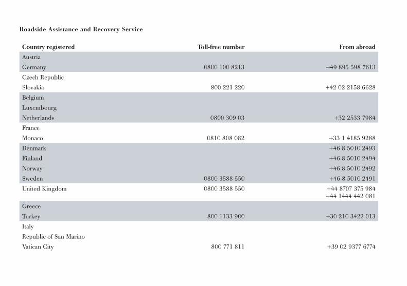
Roadside Assistance and Recovery Service
Country registered Toll-free number From abroad
Austria
Germany 0800 100 8213 +49 895 598 7613
Czech Republic
Slovakia 800 221 220 +42 02 2158 6628
Belgium
Luxembourg
Netherlands 0800 309 03 +32 2533 7984
France
Monaco 0810 808 082 +33 1 4185 9288
Denmark +46 8 5010 2493
Finland +46 8 5010 2494
Norway +46 8 5010 2492
Sweden 0800 3588 550 +46 8 5010 2491
United Kingdom 0800 3588 550 +44 8707 375 984 +44 1444 442 081
Greece
Turkey 800 1133 900 +30 210 3422 013
Italy
Republic of San Marino
Vatican City 800 771 811 +39 02 9377 6774
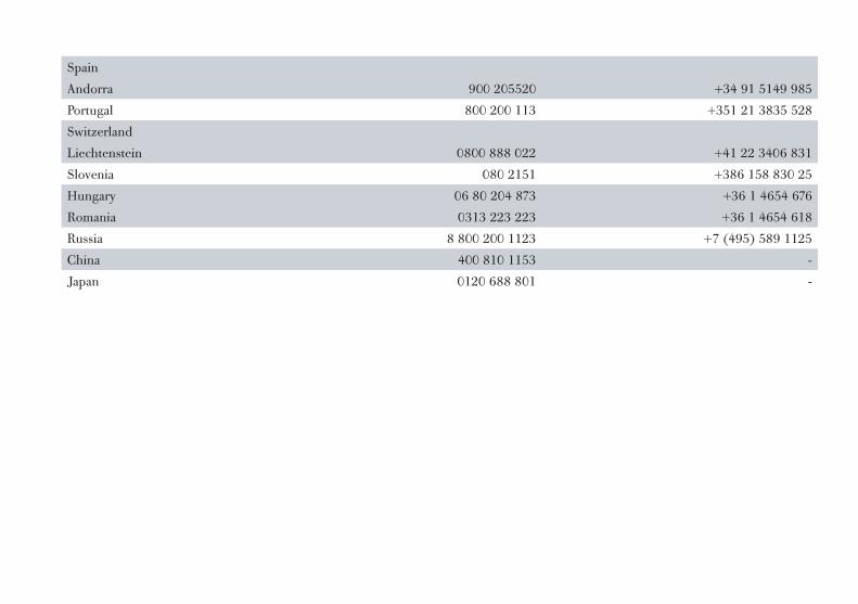
Spain
Andorra 900 205520 +34 91 5149 985
Portugal 800 200 113 +351 21 3835 528
Switzerland
Liechtenstein 0800 888 022 +41 22 3406 831
Slovenia 080 2151 +386 158 830 25
Hungary 06 80 204 873 +36 1 4654 676
Romania 0313 223 223 +36 1 4654 618
Russia 8 800 200 1123 +7 (495) 589 1125
China 400 810 1153 -
Japan 0120 688 801 -
Code no. 84063400Catalogue no. 3849/11
EDITION
1st edition October 2011
EDITING
STAR s.r.l.Alessandria - Italia
PRINTING
STAR s.r.l.Alessandria - Italia
Technical Service DepartmentVia Abetone Inferiore, 4
41053 MaranelloModena - Italia
Equipment and options in Ferrari vehicle models may vary because of specific legal and market requirements. The information contained in this publication is therefore not binding in any way. Ferrari reserves the right to make any modification to the vehicle models described in this manual, at any time, for either technical or commercial reasons.Contact the nearest Ferrari Dealer for any further information you may require.In the interests of efficiency and safety, as well as to preserve the value of the vehicle, we do not recommend modifying the equipment using non-approved parts.