Embed Size (px)
Citation preview

Banks Derringer®
Tuner 2014-2017 3.0L EcoDiesel Ram 15002014-2017 3.0L EcoDiesel Jeep Grand Cherokee
THIS MANUAL IS FOR USE WITH SYSTEM 66541, 66571, & 66572
Gale Banks Engineering 546 Duggan Avenue • Azusa, CA 91702 (626) 969-9600 • Fax (626) 334-1743
Product Information & Sales: (888) 635-4565Customer Support: (888) 839-5600 Installation Support: (888) 839-2700
bankspower.com
1/16/2018 PN 97282 v.3.0©2018 Gale Banks Engineering
Owner’sManualwith Installation Instructions
2 97282 v.3.0
Dear Customer,
If you have any questions concerning the installation of your Banks Techni-Cooler, please call our Technical Ser-vice Hotline at (888) 839-2700 between 7:00 am and 4:00 pm (PT). If you have any questions relating to shipping or billing, please contact our Customer Service Department at (888) 839-5600.
Thank you.
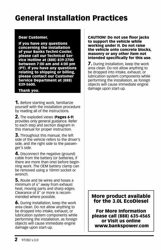
1. Before starting work, familiarize yourself with the installation procedure by reading all of the instructions.
2. The exploded views (Pages 6-9) provides only general guidance. Refer to each step and section diagram in this manual for proper instruction.
3. Throughout this manual, the left side of the vehicle refers to the driver’s side, and the right side to the passen-ger’s side.
4. Disconnect the negative (ground) cable from the battery (or batteries, if there are more than one) before begin-ning work. The OEM battery clamp can be removed using a 10mm socket or wrench.
5. Route and tie wires and hoses a minimum of 6" away from exhaust heat, moving parts and sharp edges. Clearance of 8" or more is recom-mended where possible.
6. During installation, keep the work area clean. Do not allow anything to be dropped into intake, exhaust, or lubrication system components while performing the installation, as foreign objects will cause immediate engine damage upon start-up.
CAUTION! Do not use floor jacks to support the vehicle while working under it. Do not raise the vehicle onto concrete blocks, masonry or any other item not intended specifically for this use.
7. During installation, keep the work area clean. Do not allow anything to be dropped into intake, exhaust, or lubrication system components while performing the installation, as foreign objects will cause immediate engine damage upon start-up.
General Installation Practices
More product available for the 3.0L EcoDiesel
For More Information please call (888) 635-4565
or Visit us online www.bankspower.com

97282 v.3.0 3
TOOLS REQUIRED: • Metric sockets and wrenches• Hooked Pick• Diagonal (side cutter) Pliers • Exacto knife or other small bladed knife• Drill motor*• #31 (.1200 dia.) Drill bit*• #1 or 7/32 (.228 dia.) Drill bit**Required only if mounting switch in dash
Highly recommended tools and supplies:• Standard and Phillips screwdrivers• Silicon sealer (black or clear recommended)• Metal coat hanger
Table of Contents
Section 1 ...................................... 10
Installation of wiring Harness,
Connections and Derringer Tuner
Section 2 ...................................... 22
Operation of the Derringer
Section 3 ...................................... 24
Troubleshooting
Section 4 ...................................... 27
Placement of the Banks Power Decals

4 97282 v.3.0
Disclaimer of Liability
Gale Banks Engineering Inc., and itsdistributors, employees, and dealers(hereafter “SELLER”) shall in no way beresponsible for the product’s proper useand service. The BUYER hereby waivesall liability claims.
The BUYER acknowledges that he/she is not relying on the SELLER’s skillor judgment to select or furnish goodssuitable for any particular purposeand that there are no liabilities whichextended beyond the descriptionon the face hereof and the BUYERhereby waives all remedies or liabilities,expressed or implied, arising by lawor otherwise, (including withoutany obligations of the SELLER withrespect to fitness, merchantability, andconsequential damages) whether or notoccasioned by the SELLER’s negligence.The BUYER is responsible to fullyunderstand the capability and limitationsof his/her vehicle according tomanufacturer specifications and agreesto hold the SELLER harmless from anydamage resulting from the failure toadhere to such specifications.
The SELLER disclaims any warrantyand expressly disclaims any liability
for personal injury or damages. TheBUYER acknowledges and agreesthat the disclaimer of any liability forpersonal injury is a material term for thisagreement and the BUYER agrees toindemnify the SELLER and to hold theSELLER harmless from any claim relatedto the item of the equipment purchased.Under no circumstances will the SELLERbe liable for any damages or expensesby reason of the use or sale of any suchequipment.
The BUYER is responsible to obey allapplicable federal, state, and local laws,statutes, and ordinances when operatinghis/her vehicle, and the BUYER agreesto hold SELLER harmless from anyviolation thereof.
The SELLER assumes no liabilityregarding the improper installationor misapplication of its products. It isthe installer’s responsibility to checkfor proper installation and if in doubt,contact the manufacturer.
The BUYER is solely responsible for allwarranty issues from the automotivemanufacturer.
Disclaimers
THIS IS A HIGH PERFORMANCE PRODUCT. USE AT YOUR OWN RISK. Do not use this product until you have carefully read the following agreement.
This sets forth the terms and conditions for the use of this product. The installation of this product indicates that the BUYER has read and un-derstands this agreement and accepts its terms and condi-tions.

97282 v.3.0 5
Limitation of Warranty
Gale Banks Engineering Inc. (hereafter“SELLER”), gives Limited Warranty asto description, quality, merchantability,fitness for any particular purpose,productiveness, or any other matter ofSELLER’s product sold herewith. TheSELLER shall be in no way responsiblefor the product’s open use and serviceand the BUYER hereby waives all rightsexcept those expressly written herein.This Warranty shall not be extendedor varied except by written instrumentsigned by SELLER and BUYER.Please see enclosed warrantyinformation card, or go towww.bankspower.com/warranty,for warranty information regardingyour product. All products that are inquestion of Warranty must be returnedshipping prepaid to the SELLER andmust be accompanied by a dated proofof purchase receipt. All Warranty claimsare subject to approval by Gale BanksEngineering Inc.
Under no circumstance shall the SELLERbe liable for any labor charged or traveltime incurred in diagnosis for defects,removal, or reinstallation of this product,or any other contingent expense.
Under no circumstances will the SELLERbe liable for any damage or expensesincurred by reason of the use or sale ofany such equipment.
IN THE EVENT THAT THE BUYER DOES NOT AGREE WITH THIS AGREEMENT:
The BUYER may promptly return this product, in a new and unused condition, with a dated proof-of-purchase, to the placeof-purchase within thirty (30) days from date-of-purchase for a full refund, less shipping and/or restocking fee.
The installation of this product indicates that the BUYER has read and understands this agreement and accepts its terms and conditions.

6 97282 v.3.0
Wiring Diagram: Stand Alone Tuner Configuration
FRP
EGT
MAP
Terminator Cap
(Black Color)PN: 61300-22
OR
NOTICE:Ram 1500 only
NOTICE:Jeep Grand
Cherokee only
NOTICE:EGT install is
optional

97282 v.3.0 7

8 97282 v.3.0
Wiring Diagram: iDash 1.8" Configuration
FRP
EGT
MAP
NOTICE:Black colored
cap is required
NOTICE:EGT install is
optional

97282 v.3.0 9
NOTICE:Up to four iDash
1.8’s can be used. Additional gauges requres
a Y-cable.

10 97282 v.3.0
1. Disconnect the battery ground cables from each battery (if so equipped). Secure the cables so that they do not come in contact with the battery posts during the installation.
2. Remove the engine cover for:
a. The Ram 1500, by first removing the oil filler cap. Then, lift up at the front to release the rubber socket mounts and pull forward to release from rear mounts.
Reinstall oil filler cap. See Figure 1.
b. The Jeep Grand Cherokee, by lifting up at each corner to release the rubber socket mounts. See Figure 2.
If installing in a Jeep Grand Cherokee, skip steps 3 and 4 and proceed to step 5.
Section 1INSTALLATION OF WIRING HARNESS, CONNECTIONS & DERRINGER TUNER
Figure 2
Figure 1Ram 1500
Grand Cherokee

97282 v.3.0 11
3. Disconnect the Mass Air Flow (MAF) sensor connector by first lifting up on the red lock slider until it releases, then depress the connector latch and lift the connector away from the sensor.
4. Remove the airbox and intake duct by first loosening the compressor inlet duct hose clamp at the compressor (see Figure 3) - 5/16 socket, extensions, ratchet. Unhook each of the latches securing the airbox lid to the airbox, lift up on the outer edge of the airbox cover to release the finger catches, then lift up on the intermediate plastic tube / silencer to disengage it from the rubber mount and remove the assembly from the vehicle. See Figure 4.
Cover the compressor inlet & air filter with clean rags to prevent foreign objects from accidentally entering the induction system while installing the Derringer tuner.
5. Remove the black acoustic foam covering the passenger side camshaftcover and EGR cooler outlet pipe. See Figure 4.
6. Locate the Fuel Rail Pressure (FRP) sensor and Temperature / Manifold Absolute Pressure (TMAP) Sensor. See Figure 5.
Figure 5
Figure 3
Figure 4
12 97282 v.3.0
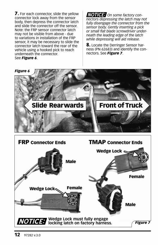
7. For each connector, slide the yellow connector lock away from the sensor body, then depress the connector latch and slide the connector off the sensor. Note: the FRP sensor connector latch may not be visible from above - due to variations in installation of the FRP sensor, it may be necessary to slide the connector latch toward the rear of the vehicle using a hooked pick to reach underneath the connector. See Figure 6.
On some factory con-nectors depressing the latch may not fully disengage the connector from the sensor body. Gently inserting a pick or small flat blade screwdriver under-neath the leading edge of the latch while depressing will aid release.
8. Locate the Derringer Sensor har-ness (PN 62683) and identify the con-nectors. See Figure 7.
Figure 6
Wedge Lock must fully engage locking latch on factory harness. Figure 7

97282 v.3.0 13
9. Connect the male ends of both the FRP and TMAP Derringer harness to the sensors on-engine. Pay specific attention to the connector latch orientation and engagement, making sure that the connector fully engages the sensor and latches in place. Check each connection by pulling firmly on the connector body after latching - note that the male Derringer harness connectors do not use a sliding connector lock, only a latch.
Pay specific attention to the orientation of Female TMAP connector in the following step. Damage can result with improper connection. Wedge lock on female TMAP connector (Derringer Harness) must be oriented on same side as connector locking latch and yellow lock (OEM Engine Harness).
10. Connect the female ends of both the FRP and TMAP Derringer harness to the factory harness, again making sure that the connector bodies are oriented properly and latch securely when connected. Slide the factory harness connector locks into place, and confirm that the connections are secure by tugging firmly on either side of the junction. Secure the harness connectors to the engine with supplied zipties.
11. EGT Harness Install
– This enables “Full Power Extension” mode in Derringer. This is optional and not required to achieve increased power levels. Connecting this harness extends the duration of maximum power by 10 seconds. If EGT intercept is not used, connect the male and female connectors of the Derringer harness, and zip tie the branch in a safe location. See Figure 9
Figure 9
Figure 8
OPTIONAL
Passenger side underneath
Front of truck
If not used
Ram 1500
Transmission
Due to the difficulty of accessing the EGT connector, the installation of the EGT intercept channel (steps 11-13) is optional. It is recommended that only advanced installers perform these steps.
ADVANCED USER ONLY

14 97282 v.3.0
Ram 1500 – EGT intercept
From underneath the vehicle, locate the Exhaust Gas Temperature (EGT) connector located on the passenger’s side of the transmission. See Figure 8. Route the EGT branch of the Derringer harness down behind the engine on the passenger’s side to this connector location. Disconnect the factory EGT connection. Note: It may be easier to disconnect this connection if the connector is removed from its mounting tab.
Grand Cherokee – EGT Intercept
Remove underbody tray beneath the transmission. Locate the harness
that runs along the driver side of the transmission. See Figure 10.
Trace the EGT sensor connector branch of the harness. (Thinner branch at the harness split) See Figure 11.
Unsecure the EGT harness branch from a tie down located above the transmission. Unlock the EGT connector by sliding the yellow connector lock, and disconnect the factory EGT Connection.
Route the EGT branch of the Derringer harness along the driver side firewall. Ensure the harness is away from the exhaust manifold and secure the harness.
Figure 10
Figure 11
Grand Cherokee
Grand Cherokee

97282 v.3.0 15
12. Connect the female factory EGT
connector to the male connector
on the Derringer harness and the
male factory connector to the
female connector on the Derringer
harness. Ensure that the connector
locks are fully engaged. Confirm the
connections are secure by tugging
firmly on both sides of the connection.
Do not pull on the wires but only the
plastic connectors. If the connector
was removed from its mounting tab,
reinstall the connector on the mounting
tab.
13. Secure the Derringer harness to
the factory drip tray at the top of the
firewall. Run the harness towards the
driver’s side fender and secure using
the supplied zip ties. See Figure 12.
Secure the EGT branch of the harness
away from hot exhaust components.
14. Connect the Derringer module to the sensor harness and then connect it to the Derringer Starter Cable. If using the 3-position switch, on a Ram 1500 install the gray Dust Cap on the Derringer. If using the 3 position switch on a Jeep Grand Cherokee or when using a iDash 1.8, install the black Terminator Cap. Once the correct cap is in place rotate the locking ring clockwise to secure the cap. Then locate a place to secure the Derringer module, along the driver’s side fender, and tie-wrap it in place.
If installing in a Jeep Grand Cherokee, skip steps 15-17 and proceed to step 18.
Jeep Grand Cherokee requires the use of black Terminator Cap at all times. Once the correct cap is in place rotate the locking ring clockwise to secure the cap. Then locate a place to secure the Derringer module, along the driver’s side fender, and tie-wrap it in place. If installing in a Jeep Grand Cherokee, skip steps 15-17 and proceed to step 18.
Figure 12

16 97282 v.3.0
The starter cable and cap contain alignment marks at the 12 o’clock position and a locking ring with a tab. First rotate the locking ring towards the 12o-clock position then connect the mating ends together ensuring proper alignment using the 12 o’clock marks Figure 13.
Then rotate the locking ring towards the lock icon until you feel a click to secure the cable or cap. Figure 14.
Figure 13
Figure 14

97282 v.3.0 17
15. To route the Derringer starter cable through the firewall, we recommend taking advantage of the removable factory clutch master cylinder block-off plate. From inside the cab of the vehicle, locate the two studs / nuts protruding into the cab, above and to the right of the steering shaft firewall pass-through. See Figure 15. Remove the nuts, then push the blockoff plate free of the firewall (pressing on the backside of the plate \ through the center opening in the firewall) to release the factory adhesive backing.
16. From the engine bay side of the firewall, locate and remove the block-off plate. Secure it in a vice, and drill a 3/16” pilot hole in the center of the plate. See Figure 16. Enlarge the hole to 9/16”, to allow the smaller connector of the Derringer Starter Cable to pass through the block-off plate from the engine compartment side, so it comes out in the same direction the mounting bolts face. See Figure 17. Then reinstall the blockoff plate, taking care to not pinch or trap any wires.
Figure 16
Figure 17
Figure 15
Ram 1500
Ram 1500
Ram 1500

18 97282 v.3.0
17. Re-install the block off plate mounting nuts onto the studs from the inside of the cab. Then carefully pull the remaining free length of the Derringer Starter Cable through the firewall. Be sure to leave a little slack on the engine bay side of the firewall.
18. For the jeep Grand Cherokee, route the smaller connector fo the Derringer Starter Cable through the EOM grommet (behind the brake pedal) from the engine-side of the firewall. See Figure 18 Feed a straightened metal coat hanger through the firewall from the inside of
the vehicle and then attach the wire to it. Then gently pull them back through the firewall. The EOM grommet may need to be cut to create extra room for the additional wires. Take care to not pinch or trap any wires.
19. Plug the OBDII cable into the OBDII port under the dash Figure 19.
Figure 18
Figure 19
Grand Cherokee

97282 v.3.0 19
NOTE: If using the Switch configuration, perform steps 20-22. If using iDash 1.8" Gauge configuration, skip to step 23.
20. Plug the 4-pin connector from the OBDII cable, the 6-pin connector from the starter cable, and the 2-pin connector from the switch cable into the Y-harness Figure 20.
21. Install the power level plate to the switch. Make sure to align the slot of the switch with the red line on the plate towards Sport Figure 21.
22. OPTIONAL: Mount switch in dashboard by drilling two holes using the supplied template (see page 20). Be careful to not damage factory wiring behind the dashboard. To keep the switch from rotating, it is necessary to install the locking tab washer behind the dash, with the locking tab facing the backside of the dash face. Alternatively, Zip tie the switch in any easy to access location for power level adjustment.
NOTE: Only perform steps 23-25 if using iDash gauge configuration. If using the switch configuration skip to step 26.
Figure 20
Figure 21

20 97282 v.3.0
23. Plug the 6 pin in-cab terminator cable into the 6 pin plug on the iDash 1.8. Then plug the 6 pin starter cable into the in-cab terminator plug. Plug the 4 pin OBD2 Cable into the 4 pin plug on the iDash 1.8. Figure 22
If using multiple iDash 1.8s, you can “daisy chain” them and add each additional gauge into bus using a y-cable Figure 23.
24. Install iDash gauge in an A-pillar, steering column, or suction cup windshield mount gauge pod.
25. Insure the black terminator cap is installed onto the Derringer when using the Derringer in iDash 1.8” gauge configuration Figure 24.
Figure 24
Figure 22 Figure 23
In Cab Terminator
6 pin starter cable
4 pin OBD2 cable
Y- cable
6 pin starter cable
4 pin OBD2 cable
In Cab Terminator

97282 v.3.0 21
26. Secure the harness connectors under the dash, avoiding any moving parts, with supplied Zip ties.
27. Double-check all wire harness routing under the hood and the dash for proper clearance around moving parts and sharp objects as well as heat sources, then use the supplied nylon tie straps to secure the wire harnesses safely away from any control linkages and the operator’s feet underneath the dashboard. Be sure to step on the brake and E-brake pedals and move the tilt column and adjustable peddles, if equipped, when checking for proper harness clearance. Also turn the steering wheel lock to lock to ensure that the harness does not hit, pull or otherwise interfere with any moving or hot parts of the truck.
28. Re-attach any previously removed interior trim panels, reinstall the acoustic foam engine intake cover and oil fill cap and lower the vehicle. Re-connect the negative battery cable.
29. Start the vehicle, checking for normal engine operation.
30. Check for proper device operation as follows:
While engine is running, check the LED indicator on the derringer. Under proper operation the LED will be blinking green. If LED is always off or blinking Red refer to troubleshooting section.
If connected to the iDash Gauge:
Load the “Derringer” layout and use the “up” and “down” arrows buttons to adjust the Power Level settings. If Power Level cannot be adjusted, refer to troubleshooting section.
NOTICE: Go over the entire installation as a precautionary check to ensure that all clamps are tight, wiring and hoses are properly routed, and connections are correct and tight. Make sure that the Derringer wire harness is not lying in the way of the brake and gas pedals, or any moving parts.
If vehicle is equipped with adjustable pedals and/or column, ensure that the harness is clear through the full range of adjustments.

22 97282 v.3.0
Setting Desired Power Level:The Derringer is equipped with multiple power levels. You can set the desired power level while the engine is running but it is recommended that you do not switch power level under high load applications.
Switch configuration:
There are 3 power levels when configured with a switch. These are Sport, Plus and Stock mode:
iDash 1.8 configuration:
When the Derringer is connected to an iDash 1.8, there are a total of 6 power levels. These Level 6, 5, 4, 3, 2 and stock. The power level can be changed by pressing the “up” and “down” buttons at any time. If you have the derringer layout loaded, you will see the power level change at the bottom left corner. See figure (Figure 25 ) If you have any other layout loaded, a message box will pop up to notify you of the power level change.
NOTICE: Max power in level 6 is identical to Sport using the switch configuration. The iDash adds more intermediate power levels between stock and sport calibrations.
Level 6/SPORT MODE (switch up)
Level 6/SPORT MODE (switch up) This mode is to be used when peak engine performance is required. This mode has been optimized for maximum power output and is tuned to increase fuel deliver and boost to provide maximum power output of the engine along with improved turbo response. This mode includes the Banks Full Power Extension feature that increases the allowable exhaust gas temperature (EGT) for a limited duration. This allows the engine to continue to operate at peak performance for an extended period of time. This has a significant impact on the extended performance of the engine and has a significant impact on the ¼ mile times. This functionality is only enabled if the optional EGT intercept harness is installed.
LEVEL 3/PLUS MODE (switch down)
The plus calibration is designed for use in everyday driving. This power level adds a noticeable punch under high load acceleration by improving turbo response and power. Power in this mode can be sustained for a prolonged duration.
STOCK MODE (switch middle)
Stock mode turns OFF your Derringer tuner and bypasses all signals. Throttle response and power return to stock levels.
Section 2 OPERATION OF THE DERRINGER MODULE
Figure 25
97282 v.3.0 23
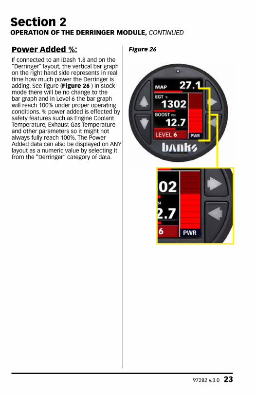
Power Added %:If connected to an iDash 1.8 and on the “Derringer” layout, the vertical bar graph on the right hand side represents in real time how much power the Derringer is adding. See figure (Figure 26 ) In stock mode there will be no change to the bar graph and in Level 6 the bar graph will reach 100% under proper operating conditions. % power added is effected by safety features such as Engine Coolant Temperature, Exhaust Gas Temperature and other parameters so it might not always fully reach 100%. The Power Added data can also be displayed on ANY layout as a numeric value by selecting it from the “Derringer” category of data.
Section 2 OPERATION OF THE DERRINGER MODULE, CONTINUED
Figure 26

24 97282 v.3.0
Section 3 TROUBLESHOOTING
Normal Operation
Your Derringer Tuner has a built-in, self-diagnostic system. The status of the diagnostic system is communicated via the LED on the module. When the Derringer module is functioning properly the LED will flash green.
Derringer Not Powered
When the LED is not illuminated, the Derringer module is not powered on. If the ignition is on and the LED is not illuminated, check the connections at the vehicle sensors and ensure they are fully engaged.
No Communication with iDash 1.8
Check that your wiring matches the “Wiring Diagram – iDash 1.8”. A common error is that the wrong cap is attached to the Derringer. A BLACK termination cap must be connected to the Derringer and one an in-cab termination cable should be attached to one of the iDash 1.8s.
LED Error Code
When faults are detected, the Derringer module will flash a diagnostic code. These diagnostic codes are comprised of 2 digits. Each digit is expressed by the flashing red LED.
A code can be determined by counting the number of red flashes displayed before the LED flashes green. This is the first digit. The number of red flashes after the LED flashes green is the second digit. After the diagnostic code is displayed, additional codes will be displayed in sequence.
Once all codes are displayed the system we begin sending the codes again. The display of the codes is separated by a longer period of the LED not being illuminated. Once you have written down all diagnostic codes being displayed, consult the following tables for a description of the code along with the action to be taken.

97282 v.3.0 25
Section 3 TROUBLESHOOTING, CONTINUED
Code Event Course of Action
1,1
Fuel Rail Pres-sure (FRP) Input Voltage Out of Range.
Turn ignition OFF & check the male and female FRP sensor con-nectors. Turn ignition back ON & re-check for presence of code. If code does not re-appear at key ON, start engine & check for presence of code both at engine idle & under varying driving conditions.
1,2
Manifold Abso-lute Pressure (MAP) Input Voltage Out of Range.
Turn ignition OFF & check the male & female MAP sensor con-nectors. Turn ignition back ON & re-check for presence of code. If code does not re-appear at key ON, start engine & check for presence of code both at engine idle & under varying driving conditions.
1,4
Exhaust Gas Temperature (EGT) Input Volt-age Out of Range.
Turn ignition OFF & check the male & female RTD sensor con-nectors. Turn ignition back ON & re-check for presence of code. If code does not re-appear at key ON, start engine & check for presence of code both at engine idle and & varying driving condi-tions.
61312-30 Derringer Tuner (Chrysler EcoDiesel applications)
LED

26 97282 v.3.0
Code Event Course of Action
2,1
Fuel Rail Pres-sure (FRP) Output Voltage Out of Range.
Turn ignition OFF & check the male & female FRP sensor con-nectors. Turn ignition back ON & re-check for presence of code. If code does not re-appear at key ON, start engine & check for presence of code both at engine idle & under varying driving conditions.
2,2
Manifold Abso-lute Pressure (MAP) Output Voltage Out of Range.
Turn ignition OFF & check the male & female MAP sensor con-nectors. Turn ignition back ON & re-check for presence of code. If code does not re-appear at key ON, start engine & check for presence of code both at engine idle & under varying driving conditions.
2,4
Exhaust Gas Temperature (EGT) Output Voltage Out of Range.
Turn ignition OFF & check the male & female RTD sensor con-nectors. Turn ignition back ON & re-check for presence of code. If code does not re-appear at key ON, start engine & check for presence of code both at engine idle & under varying driving conditions.
3,2
Internal Module Malfunction or Intermittent Power.
Turn ignition OFF & check the male & female MAP sensor con-nectors. Turn ignition back ON & re-check for presence of code. If code does not re-appear at key ON, start engine & check for presence of code both at engine idle & under varying driving conditions.
3,4
OBDII / BanksBus CAN Communication error
Turn ignition OFF & check the following connections (as appli-cable):
1) 61300-35 OBD-II Interface Cable - at 16-pin vehicle OBD-II & 4-pin inter-cable connectors.
2) 61301-21 Y-Adapter Cable - at 4-pin inter-cable & 6-pin inter-cable connectors.
3) 61301-20 B-Bus Starter Cable - at 6-pin inter-cable & 6-pin B-Bus Circular connectors.
4) 61300-22 B-Bus Terminator Plug - at 6-pin B-Bus Circular con-nector.
Turn ignition back ON & re-check for presence of code. If code does not re-appear at key ON, start engine & check for presence of code both at engine idle & under varying driving conditions.
61312-30 Derringer Tuner (Chrysler EcoDiesel applications) cont'd

97282 v.3.0 27
Mount switch template (step 22 on page 19)
Section 4 PLACEMENT OF THE BANKS POWER DECALS

Gale Banks Engineering 546 Duggan Avenue • Azusa, ca 91702 (626) 969-9600 • Fax (626) 334-1743
Product Information & Sales: (888) 635-4565Customer Support: (888) 839-5600 Installation Support: (888) 839-2700
bankspower.com