Embed Size (px)
Citation preview
Pro-OX 5700-E Iron Filter Installation
& Start- Up Guide
Thank you for purchasing a Clean Water System! With proper installation and a little
routine maintenance your system will be providing iron free water for many years.
Please review this start‐up guide entirely before beginning to install your system, and
follow the steps outlined for best results.
PRO-OX MEDIA CONTAINS DUST.
USE PAPER MASK AND VENTILATE AREA TO AVOID BREATHING DUST DURING
INSTALLATION
Questions?
Call us toll‐free: 1‐888‐600‐5426 or 1‐831‐462‐8500
Email us: [email protected]
See more information on our website: www.cleanwaterstore.com/resources
Clean Water Made Easy
http://www.cleanwaterstore.com
Pro-OX 5700-E Iron Filter Installation & Startup Guide
Page 2 www.cleanwaterstore.com Rev 120215
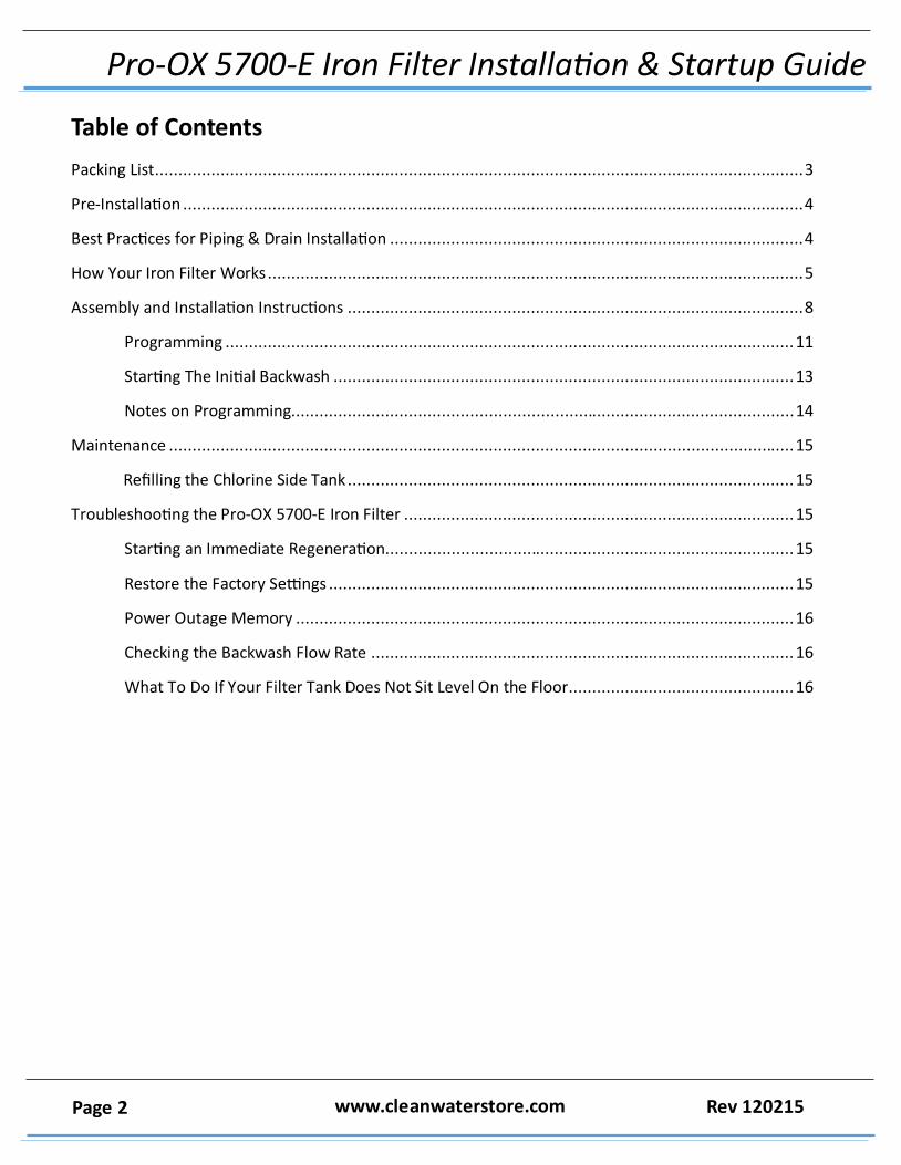
Table of Contents
Packing List .......................................................................................................................................... 3
Pre-Installation .................................................................................................................................... 4
Best Practices for Piping & Drain Installation ........................................................................................ 4
How Your Iron Filter Works .................................................................................................................. 5
Assembly and Installation Instructions ................................................................................................. 8
Programming ......................................................................................................................... 11
Starting The Initial Backwash .................................................................................................. 13
Notes on Programming........................................................................................................... 14
Maintenance ..................................................................................................................................... 15
Refilling the Chlorine Side Tank ............................................................................................... 15
Troubleshooting the Pro-OX 5700-E Iron Filter ................................................................................... 15
Starting an Immediate Regeneration....................................................................................... 15
Restore the Factory Settings ................................................................................................... 15
Power Outage Memory .......................................................................................................... 16
Checking the Backwash Flow Rate .......................................................................................... 16
What To Do If Your Filter Tank Does Not Sit Level On the Floor................................................ 16
Pro-OX 5700-E Iron Filter Installation & Startup Guide
Page 3 www.cleanwaterstore.com Rev 120215
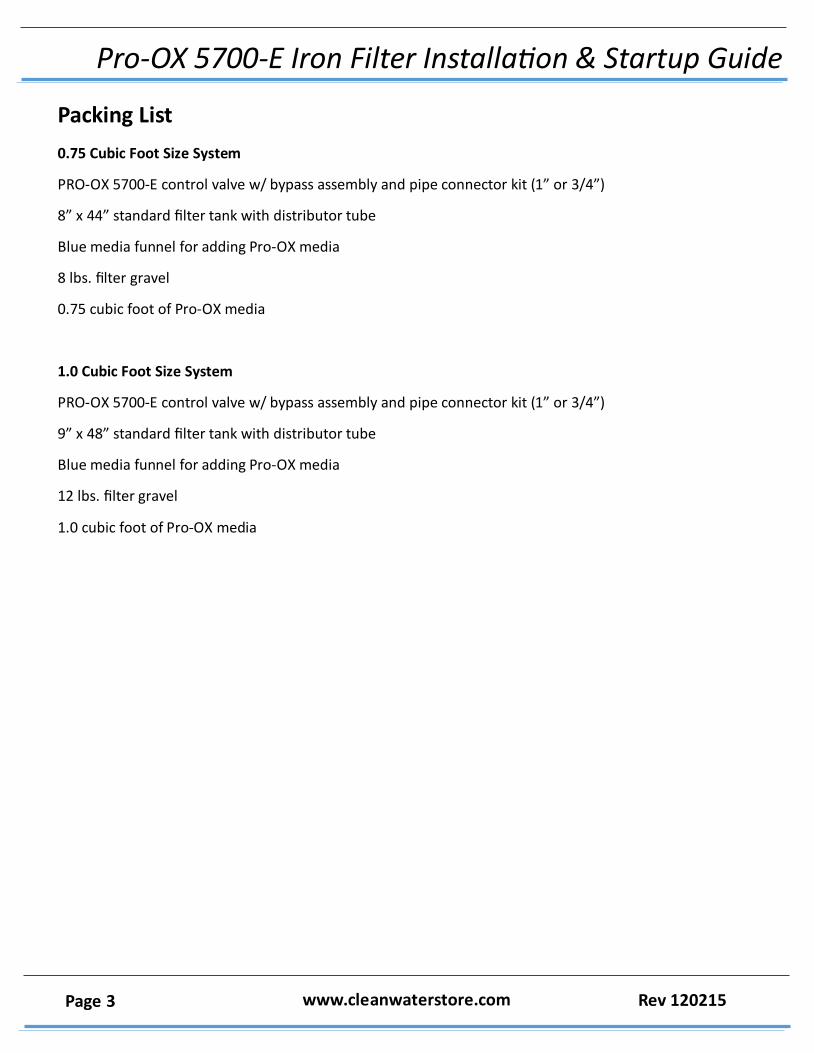
Packing List
0.75 Cubic Foot Size System
PRO-OX 5700-E control valve w/ bypass assembly and pipe connector kit (1” or 3/4”)
8” x 44” standard filter tank with distributor tube
Blue media funnel for adding Pro-OX media
8 lbs. filter gravel
0.75 cubic foot of Pro-OX media
1.0 Cubic Foot Size System
PRO-OX 5700-E control valve w/ bypass assembly and pipe connector kit (1” or 3/4”)
9” x 48” standard filter tank with distributor tube
Blue media funnel for adding Pro-OX media
12 lbs. filter gravel
1.0 cubic foot of Pro-OX media
Pro-OX 5700-E Iron Filter Installation & Startup Guide
Page 4 www.cleanwaterstore.com Rev 120215
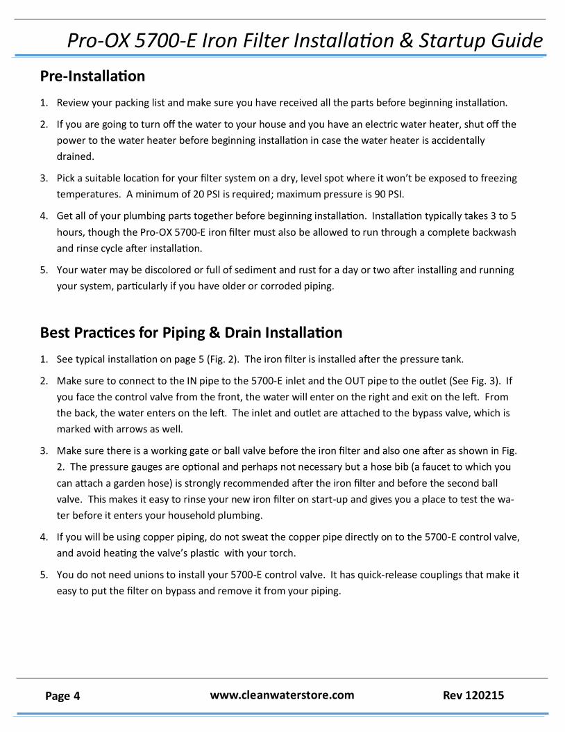
Pre-Installation
1. Review your packing list and make sure you have received all the parts before beginning installation.
2. If you are going to turn off the water to your house and you have an electric water heater, shut off the
power to the water heater before beginning installation in case the water heater is accidentally
drained.
3. Pick a suitable location for your filter system on a dry, level spot where it won’t be exposed to freezing
temperatures. A minimum of 20 PSI is required; maximum pressure is 90 PSI.
4. Get all of your plumbing parts together before beginning installation. Installation typically takes 3 to 5
hours, though the Pro-OX 5700-E iron filter must also be allowed to run through a complete backwash
and rinse cycle after installation.
5. Your water may be discolored or full of sediment and rust for a day or two after installing and running
your system, particularly if you have older or corroded piping.
Best Practices for Piping & Drain Installation
1. See typical installation on page 5 (Fig. 2). The iron filter is installed after the pressure tank.
2. Make sure to connect to the IN pipe to the 5700-E inlet and the OUT pipe to the outlet (See Fig. 3). If
you face the control valve from the front, the water will enter on the right and exit on the left. From
the back, the water enters on the left. The inlet and outlet are attached to the bypass valve, which is
marked with arrows as well.
3. Make sure there is a working gate or ball valve before the iron filter and also one after as shown in Fig.
2. The pressure gauges are optional and perhaps not necessary but a hose bib (a faucet to which you
can attach a garden hose) is strongly recommended after the iron filter and before the second ball
valve. This makes it easy to rinse your new iron filter on start-up and gives you a place to test the wa‐
ter before it enters your household plumbing.
4. If you will be using copper piping, do not sweat the copper pipe directly on to the 5700-E control valve,
and avoid heating the valve’s plastic with your torch.
5. You do not need unions to install your 5700-E control valve. It has quick-release couplings that make it
easy to put the filter on bypass and remove it from your piping.
Pro-OX 5700-E Iron Filter Installation & Startup Guide
Page 5 www.cleanwaterstore.com Rev 120215
7. The drain line tubing (not supplied) is connected to a drain from the drain outlet using flexible 1/2” ID
tubing. Note that the drain can run up above the PRO-OX 5700-E control valve and into a drain—it
does not have to drain down, as the filter backwashes under line pressure from your well pump. Most
plumbing codes require an air-gap connection, so that if your sewer or septic tank backs up, it cannot
cross connect with the drain tubing.
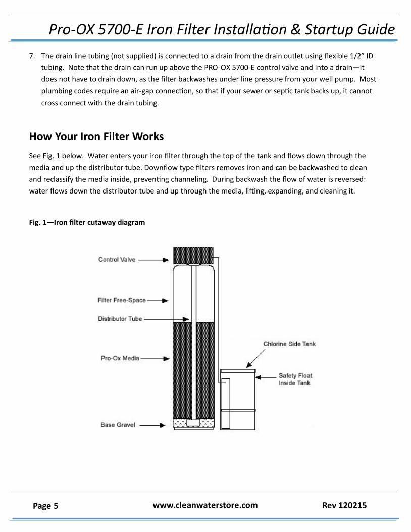
How Your Iron Filter Works
See Fig. 1 below. Water enters your iron filter through the top of the tank and flows down through the
media and up the distributor tube. Downflow type filters removes iron and can be backwashed to clean
and reclassify the media inside, preventing channeling. During backwash the flow of water is reversed:
water flows down the distributor tube and up through the media, lifting, expanding, and cleaning it.
Fig. 1—Iron filter cutaway diagram
Pro-OX 5700-E Iron Filter Installation & Startup Guide
Page 6 www.cleanwaterstore.com Rev 120215
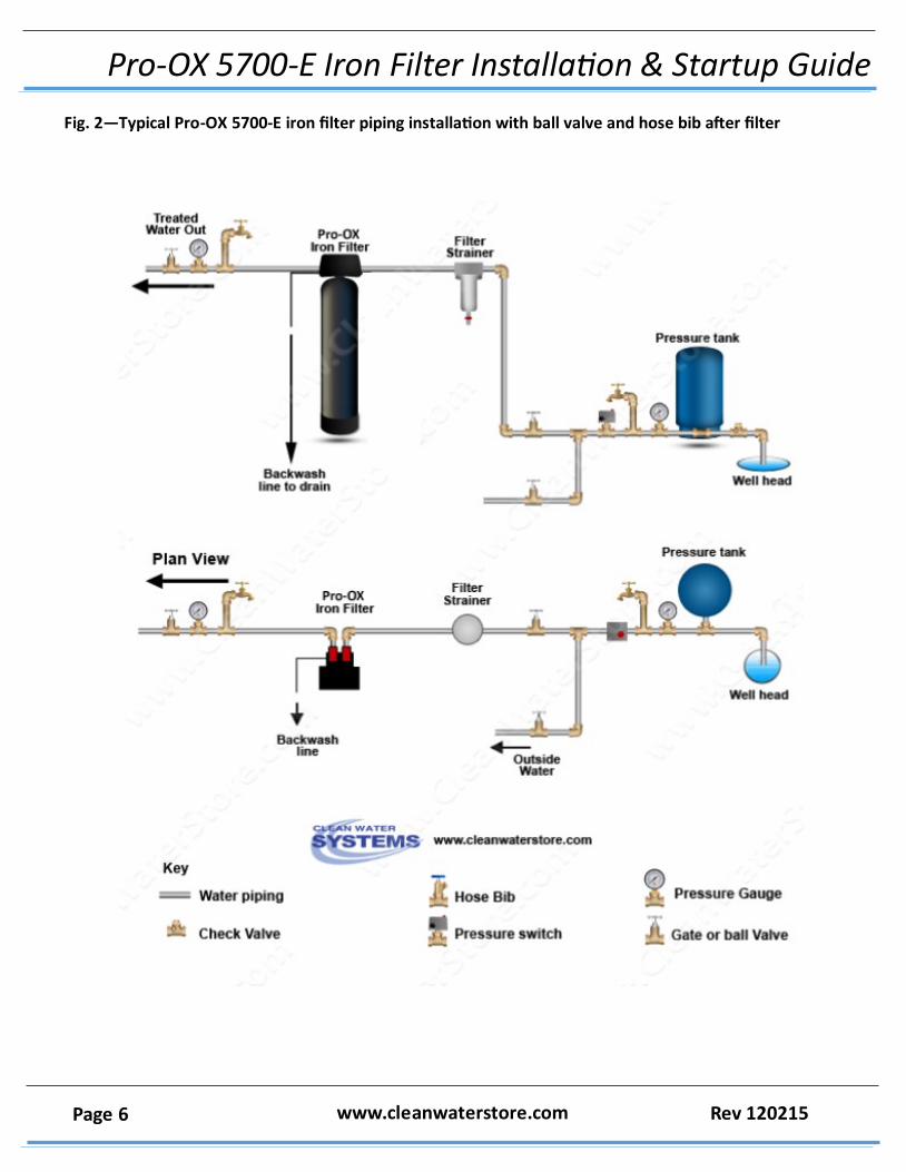
Fig. 2—Typical Pro-OX 5700-E iron filter piping installation with ball valve and hose bib after filter
Pro-OX 5700-E Iron Filter Installation & Startup Guide
Page 7 www.cleanwaterstore.com Rev 120215
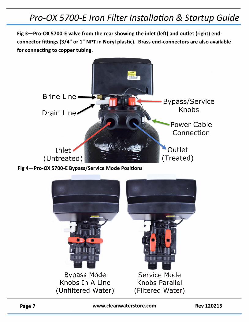
Fig 3—Pro-OX 5700-E valve from the rear showing the inlet (left) and outlet (right) end-
connector fittings (3/4” or 1” NPT in Noryl plastic). Brass end-connectors are also available
for connecting to copper tubing.
Fig 4—Pro-OX 5700-E Bypass/Service Mode Positions
Pro-OX 5700-E Iron Filter Installation & Startup Guide
Page 8 www.cleanwaterstore.com Rev 120215
Assembly and Installation Instructions
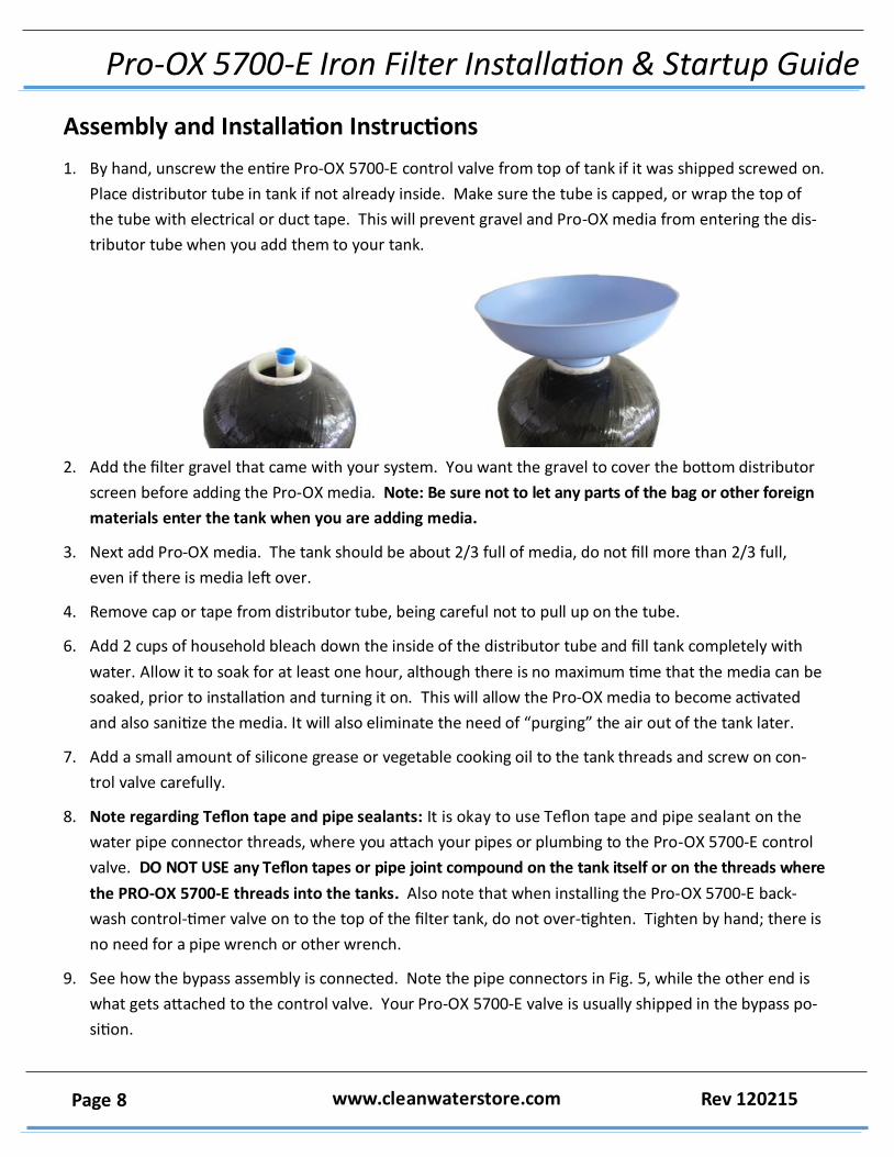
1. By hand, unscrew the entire Pro-OX 5700-E control valve from top of tank if it was shipped screwed on.
Place distributor tube in tank if not already inside. Make sure the tube is capped, or wrap the top of
the tube with electrical or duct tape. This will prevent gravel and Pro-OX media from entering the dis‐
tributor tube when you add them to your tank.
2. Add the filter gravel that came with your system. You want the gravel to cover the bottom distributor
screen before adding the Pro-OX media. Note: Be sure not to let any parts of the bag or other foreign
materials enter the tank when you are adding media.
3. Next add Pro-OX media. The tank should be about 2/3 full of media, do not fill more than 2/3 full,
even if there is media left over.
4. Remove cap or tape from distributor tube, being careful not to pull up on the tube.
6. Add 2 cups of household bleach down the inside of the distributor tube and fill tank completely with
water. Allow it to soak for at least one hour, although there is no maximum time that the media can be
soaked, prior to installation and turning it on. This will allow the Pro-OX media to become activated
and also sanitize the media. It will also eliminate the need of “purging” the air out of the tank later.
7. Add a small amount of silicone grease or vegetable cooking oil to the tank threads and screw on con‐
trol valve carefully.
8. Note regarding Teflon tape and pipe sealants: It is okay to use Teflon tape and pipe sealant on the
water pipe connector threads, where you attach your pipes or plumbing to the Pro-OX 5700-E control
valve. DO NOT USE any Teflon tapes or pipe joint compound on the tank itself or on the threads where
the PRO-OX 5700-E threads into the tanks. Also note that when installing the Pro-OX 5700-E back‐
wash control-timer valve on to the top of the filter tank, do not over-tighten. Tighten by hand; there is
no need for a pipe wrench or other wrench.
9. See how the bypass assembly is connected. Note the pipe connectors in Fig. 5, while the other end is
what gets attached to the control valve. Your Pro-OX 5700-E valve is usually shipped in the bypass po‐
sition.
Pro-OX 5700-E Iron Filter Installation & Startup Guide
Page 9 www.cleanwaterstore.com Rev 120215
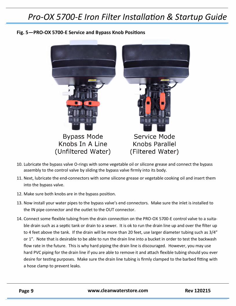
Fig. 5—PRO-OX 5700-E Service and Bypass Knob Positions
10. Lubricate the bypass valve O-rings with some vegetable oil or silicone grease and connect the bypass
assembly to the control valve by sliding the bypass valve firmly into its body.
11. Next, lubricate the end-connectors with some silicone grease or vegetable cooking oil and insert them
into the bypass valve.
12. Make sure both knobs are in the bypass position.
13. Now install your water pipes to the bypass valve’s end connectors. Make sure the inlet is installed to
the IN pipe connector and the outlet to the OUT connector.
14. Connect some flexible tubing from the drain connection on the PRO-OX 5700-E control valve to a suita‐
ble drain such as a septic tank or drain to a sewer. It is ok to run the drain line up and over the filter up
to 4 feet above the tank. If the drain will be more than 20 feet, use larger diameter tubing such as 3/4”
or 1”. Note that is desirable to be able to run the drain line into a bucket in order to test the backwash
flow rate in the future. This is why hard piping the drain line is discouraged. However, you may use
hard PVC piping for the drain line if you are able to remove it and attach flexible tubing should you ever
desire for testing purposes. Make sure the drain line tubing is firmly clamped to the barbed fitting with
a hose clamp to prevent leaks.
Pro-OX 5700-E Iron Filter Installation & Startup Guide
Page 10 www.cleanwaterstore.com Rev 120215
Optional Side Tank Installation
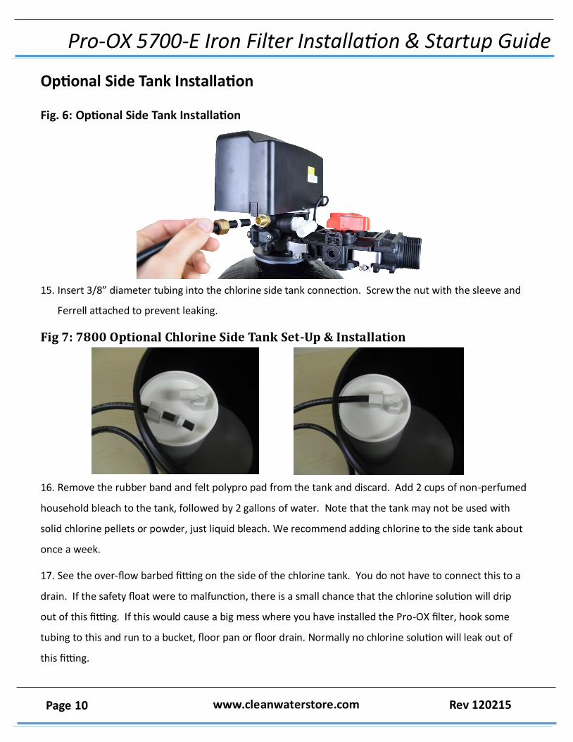
Fig. 6: Optional Side Tank Installation
15. Insert 3/8” diameter tubing into the chlorine side tank connection. Screw the nut with the sleeve and
Ferrell attached to prevent leaking.
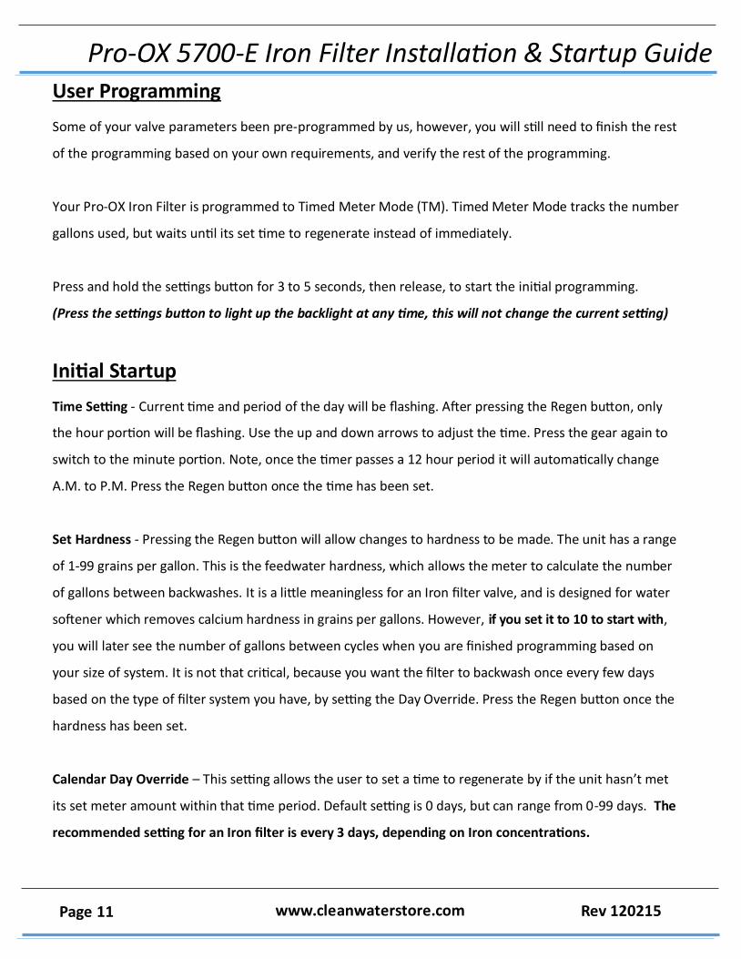
Fig 7: 7800 Optional Chlorine Side Tank Set-Up & Installation
16. Remove the rubber band and felt polypro pad from the tank and discard. Add 2 cups of non-perfumed
household bleach to the tank, followed by 2 gallons of water. Note that the tank may not be used with
solid chlorine pellets or powder, just liquid bleach. We recommend adding chlorine to the side tank about
once a week.
17. See the over-flow barbed fitting on the side of the chlorine tank. You do not have to connect this to a
drain. If the safety float were to malfunction, there is a small chance that the chlorine solution will drip
out of this fitting. If this would cause a big mess where you have installed the Pro-OX filter, hook some
tubing to this and run to a bucket, floor pan or floor drain. Normally no chlorine solution will leak out of
this fitting.
Pro-OX 5700-E Iron Filter Installation & Startup Guide
Page 11 www.cleanwaterstore.com Rev 120215
User Programming
Some of your valve parameters been pre-programmed by us, however, you will still need to finish the rest
of the programming based on your own requirements, and verify the rest of the programming.
Your Pro-OX Iron Filter is programmed to Timed Meter Mode (TM). Timed Meter Mode tracks the number
gallons used, but waits until its set time to regenerate instead of immediately.
Press and hold the settings button for 3 to 5 seconds, then release, to start the initial programming.
(Press the settings button to light up the backlight at any time, this will not change the current setting)
Initial Startup
Time Setting - Current time and period of the day will be flashing. After pressing the Regen button, only
the hour portion will be flashing. Use the up and down arrows to adjust the time. Press the gear again to
switch to the minute portion. Note, once the timer passes a 12 hour period it will automatically change
A.M. to P.M. Press the Regen button once the time has been set.
Set Hardness - Pressing the Regen button will allow changes to hardness to be made. The unit has a range
of 1-99 grains per gallon. This is the feedwater hardness, which allows the meter to calculate the number
of gallons between backwashes. It is a little meaningless for an Iron filter valve, and is designed for water
softener which removes calcium hardness in grains per gallons. However, if you set it to 10 to start with,
you will later see the number of gallons between cycles when you are finished programming based on
your size of system. It is not that critical, because you want the filter to backwash once every few days
based on the type of filter system you have, by setting the Day Override. Press the Regen button once the
hardness has been set.
Calendar Day Override – This setting allows the user to set a time to regenerate by if the unit hasn’t met
its set meter amount within that time period. Default setting is 0 days, but can range from 0-99 days. The
recommended setting for an Iron filter is every 3 days, depending on Iron concentrations.
Pro-OX 5700-E Iron Filter Installation & Startup Guide
Page 12 www.cleanwaterstore.com Rev 120215
The advanced menus should have already been programmed for you, but it is a good idea to verify the
programming before you put the filter into service.
To enter the advanced menus, press both the Gear and Regen button at the same time. All mode types will
be flashing.
Master Programming - Advanced Menus
Set Regeneration Mode – This should be set to TM for Timed Meter Mode. Timed Meter Mode tracks the
number gallons used, but waits until its set time to regenerate instead of immediately. A buffer period is
factored in to prevent you from running out of treated water.
Set Time – Verify the correct time of day is set.
P1 Backwash – This should be set to 10 minutes for an Iron Filter.
P2 Brine Draw - If you don’t have the optional side tank, set to 0, if you do, set at 30.
P3 Rapid Rinse - This should be set to 6 minutes for an Iron Filter.
BF Brine Refill - If you don’t have the optional side tank, set to 0, if you do, set to 5.
Capacity – Verify that the capacity is set correctly according to this formula:
*Gallons = (Capacity/Hardness) x .75
For a 0.75 cf unit, set at 24.
For a 1.0 cf unit, set at 32.
You are done programming your valve! Now, put it into a backwash to check for leaks, drain the media of
fines, and get the filter ready to be put into service.
Pro-OX 5700-E Iron Filter Installation & Startup Guide
Page 13 www.cleanwaterstore.com Rev 120215
Starting the Initial Backwash
1. Now you can start the initial manual backwash. Press and hold the Regen button (Button with 3 arrows)
until BW flashes and the number of minutes that you programmed (10 is default) will display. Now, unplug
the valve to stop the cycle, and proceed to the following step.
2. Very slowly turn the inlet knob on the bypass valve towards the service position, but DO NOT open the
valve all the way. We want to allow all of the air in the tank to escape before allowing the water to flow
freely. The bypass valve knobs may be a little stiff at first.
3. Once water begins to flow from the drain line open the inlet valve all the way. Continue to let the water
run from the drain line for about five minutes or until any media fines in the water are no longer present.
4. If possible verify that the backwash flow is 5 gallons per minute, which is the recommended backwash
flow rate for 1.0 and 1.5 cubic foot models. If you have a 2.5 cubic foot system it should be backwashing at
10 gallons per minute. You can easily run the drain hose to a bucket and using a watch verify the flow rate
in gallons per minute. An adequate backwash is critical to properly clean the Pro-OX media and prevent it
from cementing together.
5. Once the water is clear, press the Regen button to advance to the “Rinse” position, make sure to wait
for the display to read “RR”. Once again, allow the water to flow for about five minutes or until the water
is clear.
6. Press the Regen button to advance to the “Service” position. Next, open the outlet on the bypass valve
and then open the nearest treated water faucet to the unit and allow the water to run until it is clear. We
advise using a bathtub, laundry sink, or other fixture that does not have an aerator screen as any remain‐
ing residue may get caught in the screen.
7. Refer to your 5700-E service manual for more information about how your control valve is programmed
if desired.
Congratulations, you are done installing and your filter is ready for service!
Pro-OX 5700-E Iron Filter Installation & Startup Guide
Page 14 www.cleanwaterstore.com Rev 120215
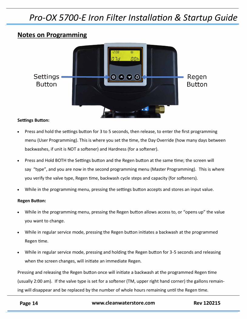
Notes on Programming
Settings Button:
Press and hold the settings button for 3 to 5 seconds, then release, to enter the first programming
menu (User Programming). This is where you set the time, the Day Override (how many days between
backwashes, if unit is NOT a softener) and Hardness (for a softener).
Press and Hold BOTH the Settings button and the Regen button at the same time; the screen will
say “type”, and you are now in the second programming menu (Master Programming). This is where
you verify the valve type, Regen time, backwash cycle steps and capacity (for softeners).
While in the programming menu, pressing the settings button accepts and stores an input value.
Regen Button:
While in the programming menu, pressing the Regen button allows access to, or “opens up” the value
you want to change.
While in regular service mode, pressing the Regen button initiates a backwash at the programmed
Regen time.
While in regular service mode, pressing and holding the Regen button for 3-5 seconds and releasing
when the screen changes, will initiate an immediate Regen.
Pressing and releasing the Regen button once will initiate a backwash at the programmed Regen time
(usually 2:00 am). If the valve type is set for a softener (TM, upper right hand corner) the gallons remain‐
ing will disappear and be replaced by the number of whole hours remaining until the Regen time.
Pro-OX 5700-E Iron Filter Installation & Startup Guide
Page 15 www.cleanwaterstore.com Rev 120215
For other valve types, the days remaining on the lower left will disappear, and just the hours left until the
Regen time will remain. To cancel, simply press and release the Regen button again.
Press and hold the Regen button. After five seconds, the screen will display GoTo BW (release the
button). After another 10-20 seconds, the screen will display BW 010 – it is now in the first stage of the
Regen cycle and the backwash timer (010) which is almost always set for ten minutes is now counting
down, but only in whole minutes. It does not show seconds.
Maintenance
Refilling the Chlorine Side Tank
We recommend adding chlorine to the chlorine side tank about once a week.
Troubleshooting the Pro-Ox 5700-E Iron Filter
Immediate Regeneration
While in service position, hold the Regen button in for 5-6 second to initiate an immediate regeneration.
Pressing the Regen button again will jump to the next cycle phase. Holding the two arrow buttons together
will terminate Immediate Regeneration and return the unit to service position. Be aware that the valve
takes at least a minute to go from one cycle to the next cycle. During this time, the screen will read (“Go
to”) its next service position.
Restore Factory Settings
Hold the Regen button while plugging in the power supply to the unit. After the unit has powered up re‐
lease Regen button. Next press the Regen button again to select no next to reset. Using the down arrow,
scroll to yes. Hitting the Gear will begin resetting the unit.
Pro-OX 5700-E Iron Filter Installation & Startup Guide
Page 16 www.cleanwaterstore.com Rev 120215
Power Outage Memory
During a loss of power, all program settings will be stored in permanent memory. The current valve posi‐
tion, cycle step and time of day are all stored as well, but upon power-up, a reset of the current time will
be necessary.
If the unit were to lose power during a regeneration stage, the valve will return back to its prior position
when the outage occurred. The unit will take 4 -5 minutes to reset back to that position.
Checking The Backwash Flow Rate
Measure the backwash flow rate by putting the system into a backwash mode and putting the drain tube
into a 5 gallon bucket and timing the flow rate. A 0.75 cubic foot system should flow at 5 gallons in one
minute, so the 5 gallon bucket should fill in one minute. The 1.0 cubic foot system should flow at 7 GPM
during backwash.
In some cases, the Pro-OX 5700-E valve has simply been programmed incorrectly. Double-check your
settings against those described above or consult your system’s service manual for instructions. In some
cases a nightly backwash is required for best results. Adjust backwash frequency to every 1 to 2 nights if
necessary.
What To Do If Your Filter Tank Does Not Sit Level On the Floor
Your black filter tank base is not glued to the bottom of your tank. Occasionally tank bases will become
crooked during shipment. If you find that that your tank does not sit level on the floor, you can easily ad‐
just it by holding the empty tank and rapping it on a concrete or solid floor once or twice in order to level
it.
Pro-OX 5700-E Iron Filter Installation & Startup Guide
Page 17 www.cleanwaterstore.com Rev 120215
Initial Backwash Media Lifted Into Control Head
Sometimes, when doing the Initial Backwash, the media gets lifted up into the control head. You can tell this
happened because you will have little or no flow, either going out to drain while in the backwash positon, or
when in the service positon.
To remove media from a control head, do the following:
1) Put the Inlet Bypass in the Closed position.
2) From the Service Mode, initiate a manual regeneration, by pressing and holding the regen button (button
on far left).
3) The valve will advance to the BW (backwash) position, and start counting down. Press the Regen button
again, and wait for the valve to advance and stop at the Rapid Rinse (RR) position.
4) With the valve in the RR position, open and close the Inlet Bypass valve several times. After the third or
fourth time, leave it in the open position and check the drain line- do you have a good solid flow? 90% of the
time, the answer is yes, but sometimes, even after opening and closing the valve many times, you still don’t
have good flow… But, in either case (good or no flow), continue…
5) With the Inlet Valve OFF, Advance the valve back to Service position again, and again press and hold the
Regen button, we are putting the valve back to the Backwash position.
6) Open the Inlet valve just enough so you can hear the water passing thru the valve- you should notice a
corresponding slow flow out of the drain line. After a minute, if there are no air bubbles present, open the
valve about another quarter inch- again, you should see a corresponding increase in the flow… And you will
continue until the valve is full open.
IMPORTANT:
Any time that you are in the Backwash or Rapid Rinse position, you may need to unplug the power- this will
hold the valve in its current position, so it doesn’t ‘time out’ and go to the next position. When you plug the
valve back in, after a minute it will return to where it was when you unplugged it (i.e. 2:32 remaining in BW).
Understand, it is not possible to jam media into the head while in Rapid Rinse, or Service, just in the Back‐
wash, when the flow direction is reversed.
What you are trying to accomplish, after you have pushed the media back in to the tank in the Rapid Rinse
position, is to get the Inlet valve all the way open in the Backwash position, without it jamming media back in
the head, and this is the part where you have to go slow, open up the Inlet valve a little bit at a time and let it
run for a few minutes- this is why you may have to unplug it- and then, once you have done that, finally, do
one more backwash, starting with the Inlet valve open, just as it will be when it does it automatically at night.
Once it does that successfully, you are done.
Pro-OX 5700-E Iron Filter Installation & Startup Guide
Page 18 www.cleanwaterstore.com Rev 120215
Changing or Adjusting the Drain Line Fitting
Step 1: Begin by shutting off the water before the system. Depressurize it by opening a faucet after the
system or in the house, then close the faucet after there is no more water coming out. Now the pressure
has been relieved from the system, however some water will come out as you do the following steps.
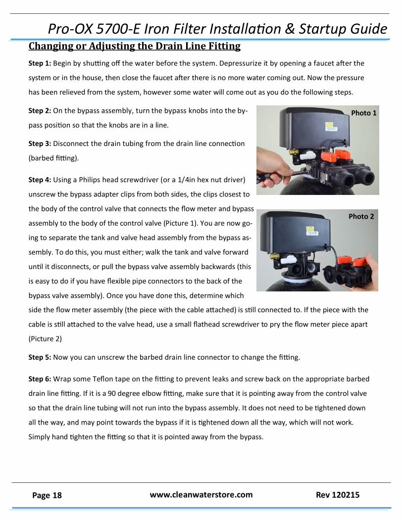
Step 2: On the bypass assembly, turn the bypass knobs into the by‐
pass position so that the knobs are in a line.
Step 3: Disconnect the drain tubing from the drain line connection
(barbed fitting).
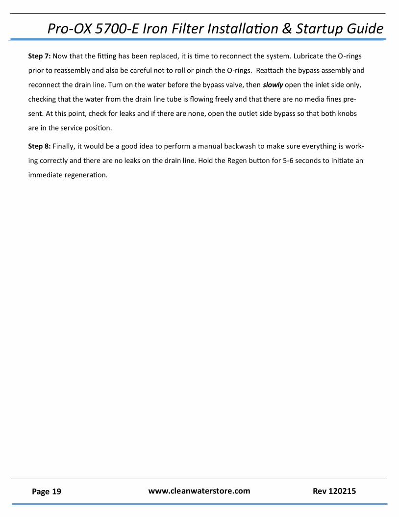
Step 4: Using a Philips head screwdriver (or a 1/4in hex nut driver)
unscrew the bypass adapter clips from both sides, the clips closest to
the body of the control valve that connects the flow meter and bypass
assembly to the body of the control valve (Picture 1). You are now go‐
ing to separate the tank and valve head assembly from the bypass as‐
sembly. To do this, you must either; walk the tank and valve forward
until it disconnects, or pull the bypass valve assembly backwards (this
is easy to do if you have flexible pipe connectors to the back of the
bypass valve assembly). Once you have done this, determine which
side the flow meter assembly (the piece with the cable attached) is still connected to. If the piece with the
cable is still attached to the valve head, use a small flathead screwdriver to pry the flow meter piece apart
(Picture 2)
Step 5: Now you can unscrew the barbed drain line connector to change the fitting.
Step 6: Wrap some Teflon tape on the fitting to prevent leaks and screw back on the appropriate barbed
drain line fitting. If it is a 90 degree elbow fitting, make sure that it is pointing away from the control valve
so that the drain line tubing will not run into the bypass assembly. It does not need to be tightened down
all the way, and may point towards the bypass if it is tightened down all the way, which will not work.
Simply hand tighten the fitting so that it is pointed away from the bypass.
Photo 1
Photo 2
Pro-OX 5700-E Iron Filter Installation & Startup Guide
Page 19 www.cleanwaterstore.com Rev 120215
Step 7: Now that the fitting has been replaced, it is time to reconnect the system. Lubricate the O-rings
prior to reassembly and also be careful not to roll or pinch the O-rings. Reattach the bypass assembly and
reconnect the drain line. Turn on the water before the bypass valve, then slowly open the inlet side only,
checking that the water from the drain line tube is flowing freely and that there are no media fines pre‐
sent. At this point, check for leaks and if there are none, open the outlet side bypass so that both knobs
are in the service position.
Step 8: Finally, it would be a good idea to perform a manual backwash to make sure everything is work‐
ing correctly and there are no leaks on the drain line. Hold the Regen button for 5-6 seconds to initiate an
immediate regeneration.