Embed Size (px)
Citation preview
Oxy‐Combustion Integration for Direct Fired sCO2 Cycles
Aaron McClung, Ph.D.
Southwest Research InstituteSan Antonio, Texas, USA
Contact:[email protected]
210‐522‐2677
Outline
• sCO2 Cycles• Oxy‐combustion• Direct Fired Cycles Evaluation• Wrap‐up
DIRECT FIRED SCO2 POWER CYCLES
11/3/2015 2015 University Turbine Systems Research Workshop 3

sCO2 Power Cycles
• Offer +3 to +5 percentage points over supercritical steam for indirect coal fired applications
• High fluid densities lead to compact turbomachinery
• Efficient cycles require significant recuperation
• Compatible with dry cooling techniques
11/3/2015 2015 University Turbine Systems Research Workshop 4
Third Generation 300 MWe S‐CO2 Layout from Gibba, Hejzlar, and Driscoll, MIT‐GFR‐037, 2006
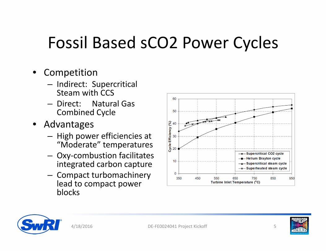
Fossil Based sCO2 Power Cycles• Competition
– Indirect: Supercritical Steam with CCS
– Direct: Natural Gas Combined Cycle
• Advantages– High power efficiencies at
“Moderate” temperatures– Oxy‐combustion facilitates
integrated carbon capture– Compact turbomachinery
lead to compact power blocks
4/18/2016 DE‐FE0024041 Project Kickoff 5

Challenges• Challenges
– 250 C thermal input temperature widow (recompression cycle) is not ideal for combustion based systems
• 400 C Combustor inlet for 650 C Turbine Inlet
• 950 C Combustor inlet for 1200 C Turbine inlet
– Flue gas cleanup for direct fired systems– Non‐trivial efficiency losses for indirect cycles
– Compact power block offset by recuperation requirements
4/18/2016 DE‐FE0024041 Project Kickoff 6
ThermalInput
OXY‐COMBUSTION
11/3/2015 2015 University Turbine Systems Research Workshop 7

Oxy‐combustion• Combustion in an oxygen rich
environment– Used for industrial applications for
achieving high combustion temperatures
– Commonly used in metal, glass, and cement industries
• Atmospheric Nitrogen is replaced by the combustion flue gas which is primarily Carbon Dioxide– Provides CO2 rich stream for
capture and sequestration– Minimizes NOx formation
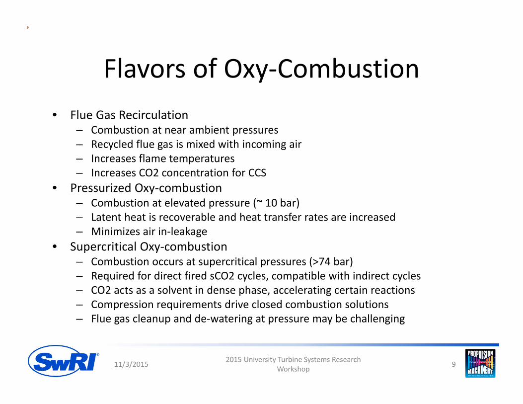
Flavors of Oxy‐Combustion• Flue Gas Recirculation
– Combustion at near ambient pressures– Recycled flue gas is mixed with incoming air– Increases flame temperatures– Increases CO2 concentration for CCS
• Pressurized Oxy‐combustion– Combustion at elevated pressure (~ 10 bar) – Latent heat is recoverable and heat transfer rates are increased– Minimizes air in‐leakage
• Supercritical Oxy‐combustion– Combustion occurs at supercritical pressures (>74 bar)– Required for direct fired sCO2 cycles, compatible with indirect cycles– CO2 acts as a solvent in dense phase, accelerating certain reactions– Compression requirements drive closed combustion solutions– Flue gas cleanup and de‐watering at pressure may be challenging
11/3/2015 2015 University Turbine Systems Research Workshop 9

Challenges
• Oxygen generation is not cheap– Cryogenic oxygen
separation is current state of the art for commercial Air Separation Units
– 250 to 360 kWh/ton of O2
• Higher power block efficiencies required to offset ASU power usage
6.00%
7.00%
8.00%
9.00%
10.00%
11.00%
12.00%
13.00%
45 47 49 51 53 55
ASU Load as % of G
ross Pow
er
Power Block Efficiency
250 kWh/ton 300 kWh/ton 350 kWh/ton
Assumes Methane at 45000 kJ/kg
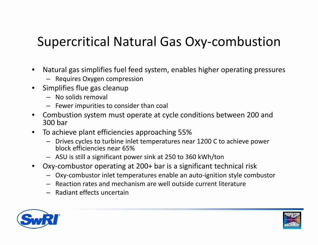
Supercritical Natural Gas Oxy‐combustion
• Natural gas simplifies fuel feed system, enables higher operating pressures– Requires Oxygen compression
• Simplifies flue gas cleanup– No solids removal– Fewer impurities to consider than coal
• Combustion system must operate at cycle conditions between 200 and 300 bar
• To achieve plant efficiencies approaching 55%– Drives cycles to turbine inlet temperatures near 1200 C to achieve power
block efficiencies near 65%– ASU is still a significant power sink at 250 to 360 kWh/ton
• Oxy‐combustor operating at 200+ bar is a significant technical risk– Oxy‐combustor inlet temperatures enable an auto‐ignition style combustor– Reaction rates and mechanism are well outside current literature– Radiant effects uncertain
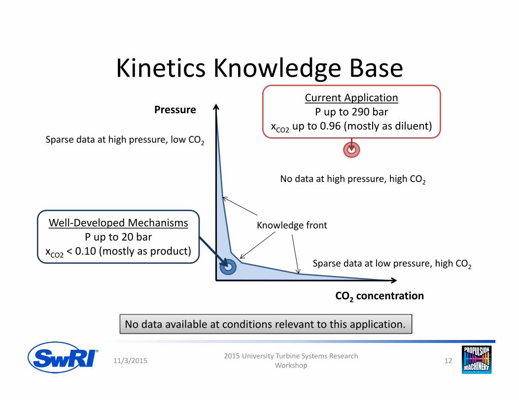
Kinetics Knowledge Base
11/3/2015 2015 University Turbine Systems Research Workshop 12
CO2 concentration
PressureCurrent ApplicationP up to 290 bar
xCO2 up to 0.96 (mostly as diluent)
Well‐Developed MechanismsP up to 20 bar
xCO2 < 0.10 (mostly as product)Sparse data at low pressure, high CO2
Sparse data at high pressure, low CO2
No data at high pressure, high CO2
Knowledge front
No data available at conditions relevant to this application.
Development Path
• System Design and Thermodynamic Analysis– Evaluate cycles to determine combustor design parameters
• System level Technology Gap Assessment• Kinetics Models
– Evaluate kinetic models to determine applicability– Initial kinetic evaluation at combustor inlet conditions
• Combustor Concept– Material constraints at 1000 C 200 bar inlet, 1200 C 200 bar outlet conditions
• Combustor demonstration
11/3/2015 2015 University Turbine Systems Research Workshop 13

SYSTEM ENGINEERING DESIGN AND THERMODYNAMIC ANALYSIS
11/3/2015 2015 University Turbine Systems Research Workshop 14
Thermodynamic Analysis
• Establish combustor operating parameters– Inlet Temperature, Pressure, mass flow– Thermal duty
• Plant models were developed and evaluated using ASPEN Plus– Incorporated secondary systems
• ASU, Cooling, Fuel Compression
– Incorporated equilibrium combustion model
10/30/2015 DE‐FE0024041 Status Update 15
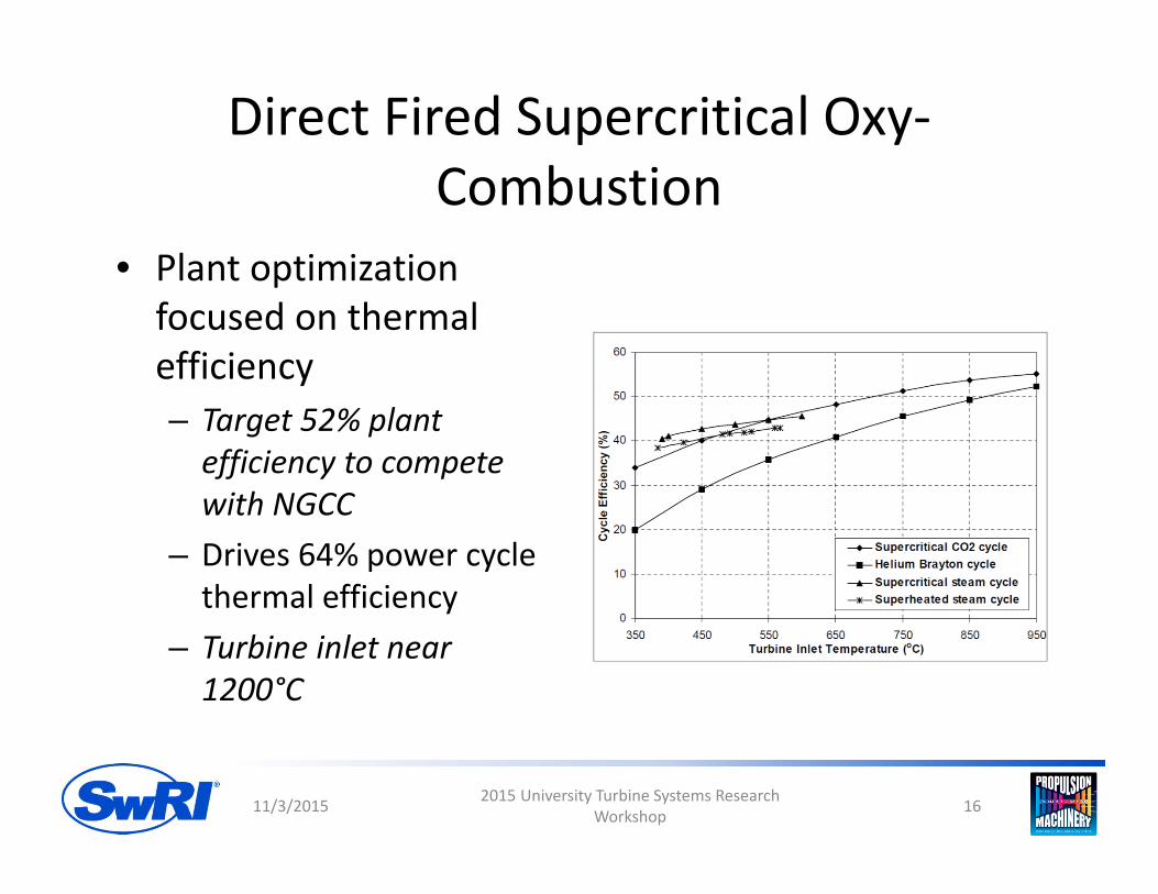
Direct Fired Supercritical Oxy‐Combustion
• Plant optimization focused on thermal efficiency– Target 52% plant efficiency to compete with NGCC
– Drives 64% power cycle thermal efficiency
– Turbine inlet near 1200°C
11/3/2015 2015 University Turbine Systems Research Workshop 16
Metrics for Cycle Evaluation
• Combustor inlet temperature• Overall cycle efficiency• Overall heat exchanger area• Volume flowrate per power out (turbine size)• Power per mass flowrate• Amount of high temperature piping/components needed
4/18/2016 DE‐FE0024041 Project Kickoff 17
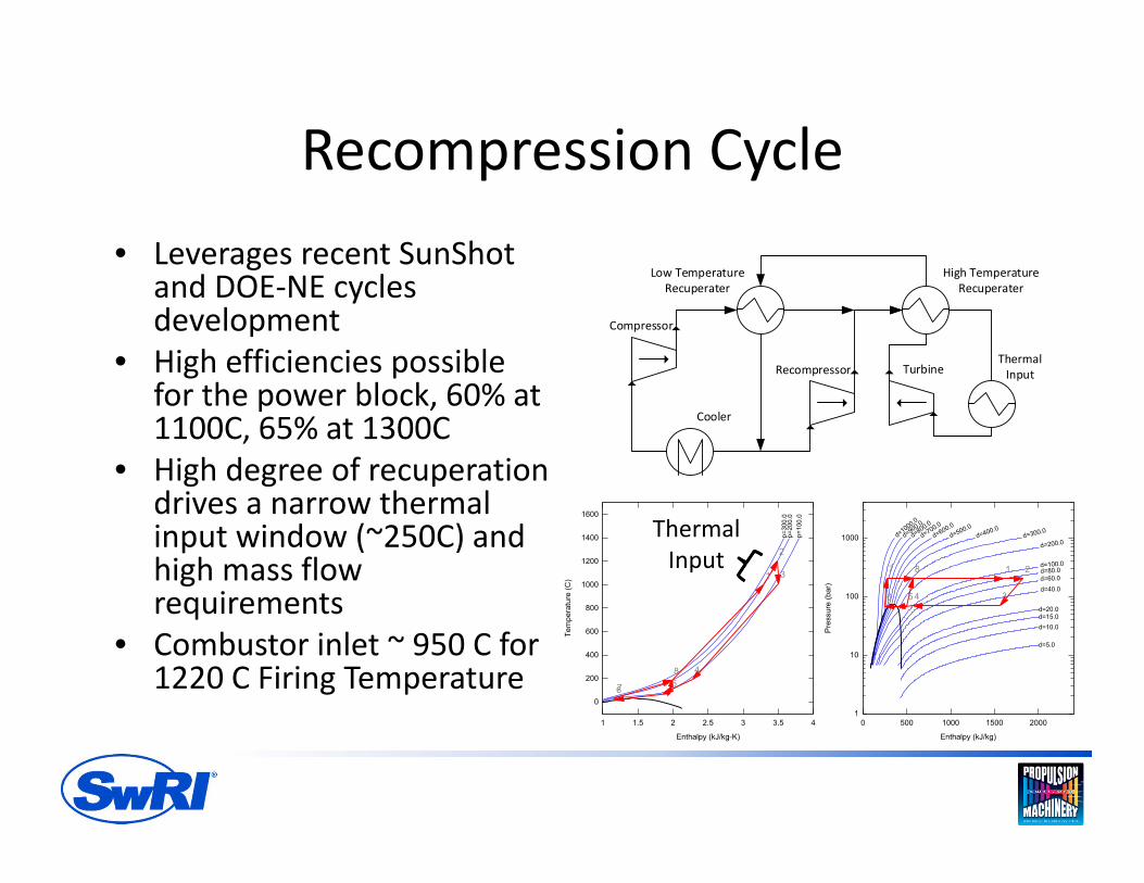
Recompression Cycle• Leverages recent SunShot
and DOE‐NE cycles development
• High efficiencies possible for the power block, 60% at 1100C, 65% at 1300C
• High degree of recuperation drives a narrow thermal input window (~250C) and high mass flow requirements
• Combustor inlet ~ 950 C for 1220 C Firing Temperature
ThermalInput
Cooler
Low TemperatureRecuperater
High TemperatureRecuperater
Turbine
Compressor
Recompressor
ThermalInput

Partial Condensation Cycle
• Trans‐critical cycle• Optimization schedules the vapor phase compression, cooling for liquefaction, and liquid pumping to reduce compression power requirements
ThermalInput
CoolerRecuperater
Turbine
Compressor
Pump
ThermalInput
DESIGN-SPECCOMPMAT C
DESIGN-SPECFUELFLOW
DESIGN-SPECFUELPRES
DESIGN-SPECO2PRES
DESIGN -SPECPINLET
DESIGN -SPECT INLET
DESIGN-SPECT MIXBAL
CALCULATORCOOLT OWR
CALCULATOREFFICIEN
CALCU LATORO2CALC
PIPELCMP
PIPLNCO2
H2OSEPER FUELCOM
W
MIXER
FUELWORK
O2PUMP
COMBUST
W
MIXER
WMIXER
COOLER
FMIX
REJ ECT HX
FSPLIT
HXLOWHXHIGH
MAINCOMP
RECOMP
EXPANDER
CO2
S15
WPIPELIN
T AKEOFF
H20
S21
S3
CH4IN
CH4PRE
FUELCW
ASUPOWW
O2PWORK
WFUELSYS
O2IN
O2PRE
INLET
S14
WMAINCOM
WRECOMP
WT URBINE
WCOOLW
WNETW
S7
S10
QRECOMPC
Q
S9
S11
MAIN
S6
QREJECT
Q
RECOMPRE
S2
S8
S1
OUT LET
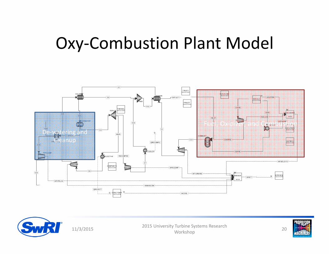
De‐watering and Cleanup
Fuel, Oxidizer, and Combustion
Oxy‐Combustion Plant Model
11/3/2015 2015 University Turbine Systems Research Workshop 20

Cycle Analysis Results
• Recompression cycle has highest efficiency by 1.8% at 200 bar, 2.7% at 300 bar
• Condensation cycle is superior in all other metrics – Reduced recuperation (~ 50%)– Lower combustor inlet temperature– Higher power density (power output / flow rate)
• Both cycle configurations are compatible with an auto‐ignition style combustor for 1200 C Turbine inlet temperatures.
11/3/2015 2015 University Turbine Systems Research Workshop 21

Cycle Comparison
Single Recuperator Condensation
Single Recuperator Condensation
Recompression Recompression
Net fuel to bus bar plantefficiency
54.03% 51.60% 56.73% 53.44%
Total Recouperation (kW) 989.91 1078.16 1163.44 1205.34HE Duty per Net PowerRatio (kW/kW)
2.48 3.21 4.34 6.55
Power per Mass Flow Ratio(kJ/kg)
399.06 335.38 268.08 183.92
Combustor Inlet Temp. (°C) 755.18 808.60 918.16 994.37Combustor Inlet Pres. (bar) 300.00 200.00 300.00 200.00** Cycles evaluated at 1200°C Turbine Inlet Temperature and unit 1 kg/s mass flow
10/30/2015 DE‐FE0024041 Status Update 22
Modeling Considerations
• Combustion Models• Equation of State• Component Assumptions• Dewatering and Cleanup• Off design• Transients

Takeaway• Supercritical oxy‐combustion has specific challenges that must be
addressed through component development• ASU power requirements drive the cycle conditions• Supercritical natural gas oxy‐combustion is feasible, has significant
development requirements– Uncertainties related to the dense phase oxy‐combustor– Fundamental combustion properties– Design for high temperature and high pressure
• Impact of water and flue gas impurities must be considered for material selection and corrosion
• High operating temperatures required to compete with NGCC– Requires material development, characterization, and certification– Impact of corrosion in hot CO2 environment not well understood – Requires advanced turbine cooling technologies for blades and seals
• Intermediate temperature combustor demonstration is a stepping stone

THANK YOU FOR YOUR ATTENTION