Embed Size (px)
Citation preview

A DIVISION OF
456 Creamery Way, Exton, PA 19341 Phone: 610.524.8800 • Fax: 610.524.8807 • Email: [email protected]
www.neutronicsinc.com
High Purity Instruments
MODEL 1100 OXYGEN ANALYZER / CONTROLLER – PERCENT RANGE
OPERATIONS MANUAL
Manual Part Number: C5-06-4900-01-0 Revision Level: A Revision Date: January 19, 2004
REMOTESENSOR
MODE
RUN FAULT ALM 1 ALM 2
20.9PERCENT OXYGEN
MODEL 1100 O2 AnalyzerNTRON
Engineered Solutions for Gas Detection and Analysis

Installation and Operations Manual
Manual Part Number: C5-06-4900-01-0
Revision Level: A Revision Date: January 19, 2004 Page iii
Table of Contents TABLE OF CONTENTS ...........................................................................................................................................................III
FOR YOUR SAFETY: ............................................................................................................................................................... V
WELCOME ............................................................................................................................................................................. VI
CHAPTER 1 – INTRODUCTION AND OVERVIEW............................................................................................................... 1-1
1.1 GENERAL ...................................................................................................................................................................1-1 1.2 FEATURES ..................................................................................................................................................................1-1 1.3 SYSTEM HARDWARE OVERVIEW ...................................................................................................................................1-3
1.3.1 Main Board...........................................................................................................................................1-3 1.3.2 Relay Board ..........................................................................................................................................1-3 1.3.3 Power Supply ........................................................................................................................................1-3 1.3.4 Display Board........................................................................................................................................1-3 1.3.5 Control Panel ........................................................................................................................................1-3 1.3.6 Sensor ...................................................................................................................................................1-3 1.3.7 Sensor Flow-Through Head....................................................................................................................1-4 1.3.8 Chassis..................................................................................................................................................1-4
1.4 ANALYZER INPUTS AND OUTPUTS ................................................................................................................................1-6 1.4.1 The Oxygen Sensor Input .......................................................................................................................1-6 1.4.2 Alarm-1 Relay Output...........................................................................................................................1-6 1.4.3 Alarm-2 Relay Output...........................................................................................................................1-6 1.4.4 Fault Relay Output................................................................................................................................1-6 1.4.5 Analog Voltage Output...........................................................................................................................1-6 1.4.6 Analog Current Output ..........................................................................................................................1-7 1.4.7 Range ID Output....................................................................................................................................1-7 1.4.8 Service Port ...........................................................................................................................................1-7
1.5 CONTROL PANEL USER INTERFACE ..............................................................................................................................1-7 1.5.1 The “UP” Pushbutton............................................................................................................................1-7 1.5.2 The “DOWN” Pushbutton .....................................................................................................................1-7 1.5.3 The “MODE” Pushbutton ......................................................................................................................1-7 1.5.4 7-Segment Alphanumeric Display ..........................................................................................................1-8 1.5.5 RUN Indicator LED ...............................................................................................................................1-8 1.5.6 Alarm-1 Indicator LED..........................................................................................................................1-8 1.5.7 Alarm-2 Indicator LED..........................................................................................................................1-8 1.5.8 Fault Indicator LED...............................................................................................................................1-8
CHAPTER 2 – SYSTEM INSTALLATION AND START-UP................................................................................................. 2-1
2.1 INSTALLING THE ANALYZER.........................................................................................................................................2-1 2.1.1 Step 1 – Locate and Mount the Analyzer unit..........................................................................................2-2 2.1.2 Step 2 – Install the Remote Sensor .........................................................................................................2-3 2.1.3 Step 3 – Install the Analyzer ..................................................................................................................2-5
2.2 STARTING UP AND COMMISSIONING THE SYSTEM ........................................................................................................2-10 2.2.1 STEP 1 – Power Up the unit ............................................................................................................... 2-10 2.2.2 STEP 2 – Calibrate the Unit ................................................................................................................ 2-11 2.2.3 STEP 3 –Set Alarm-1 and Alarm-2..................................................................................................... 2-11
Installation and Operations Manual
Manual Part Number: C5-06-4900-01-0
Revision Level: A Revision Date: January 19, 2004 Page iv
CHAPTER 3 – ANALYZER OPERATION ............................................................................................................................. 3-1
3.1 SYSTEM ORGANIZATION...............................................................................................................................................3-1 3.2 USER MODES............................................................................................................................................................3-1
3.2.1 CALIBRATE Mode & Calibration Procedure...........................................................................................3-1 3.2.2 SET/VIEW ALARM-1 Mode .................................................................................................................3-3 3.2.3 SET/VIEW ALARM-2 Mode .................................................................................................................3-4 3.2.4 VIEW ACTIVE FAULTS Mode ..............................................................................................................3-4 3.2.5 Return to RUN Mode.............................................................................................................................3-4
3.3 SYSTEM MODES ..........................................................................................................................................................3-4 3.3.1 Self-Test & Warm-up Mode ...................................................................................................................3-4 3.3.2 RUN Mode............................................................................................................................................3-4 3.3.3 ALARM-1 ACTIVE Mode......................................................................................................................3-5 3.3.4 ALARM-2 ACTIVE Mode......................................................................................................................3-5 3.3.5 FAULT ACTIVE Mode...........................................................................................................................3-5
CHAPTER 4 – MAINTENANCE AND TROUBLESHOOTING............................................................................................... 4-1
4.1 SYSTEM SETUP ...........................................................................................................................................................4-1 4.1.1 System Setup via Control panel Keypad ..................................................................................................4-1 4.1.2 System Setup via Service Port ................................................................................................................4-3 4.1.3 Change factory settings via Hardware Jumpers .................................................................................... 4-11
4.2 ROUTINE PERIODIC MAINTENANCE.............................................................................................................................4-13 4.3 TROUBLESHOOTING...................................................................................................................................................4-14
4.3.1 Fault Codes ........................................................................................................................................ 4-14
CHAPTER 5 – APPENDICES............................................................................................................................................... 5-1
5.1 APPENDIX A – SPARE PARTS LIST ..............................................................................................................................5-1 5.2 APPENDIX B – SPECIFICATIONS...................................................................................................................................5-2 5.3 APPENDIX C – ANALYZER FACTORY CONFIGURATION SETTINGS ....................................................................................5-4 5.4 APPENDIX D – CONTROL PANEL HOT-KEY FUNCTIONS ................................................................................................5-5 5.5 APPENDIX E – RANGE / OUTPUT CHART ......................................................................................................................5-6 5.6 APPENDIX F – ZERO CALIBRATION RANGE SETTINGS ...................................................................................................5-6 5.7 APPENDIX G – MSDS MATERIAL SAFETY DATA SHEET..................................................................................................5-7 5.8 APPENDIX H – WARRANTY........................................................................................................................................5-10
INTENDED USE FOR THE MODEL 1100 .......................................................................................................................... 5-10
Installation and Operations Manual
Manual Part Number: C5-06-4900-01-0
Revision Level: A Revision Date: January 19, 2004 Page v
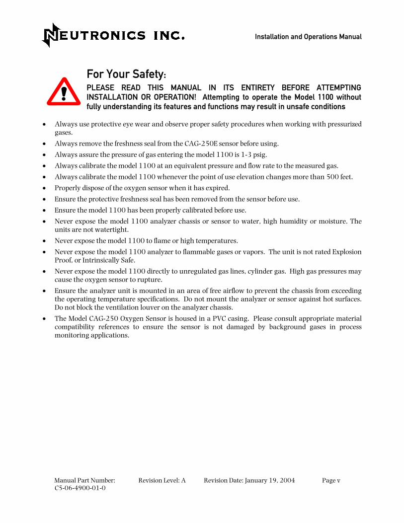
For Your Safety: PLEASE READ THIS MANUAL IN ITS ENTIRETY BEFORE ATTEMPTING INSTALLATION OR OPERATION! Attempting to operate the Model 1100 without fully understanding its features and functions may result in unsafe conditions
• Always use protective eye wear and observe proper safety procedures when working with pressurized gases.
• Always remove the freshness seal from the CAG-250E sensor before using.
• Always assure the pressure of gas entering the model 1100 is 1-3 psig.
• Always calibrate the model 1100 at an equivalent pressure and flow rate to the measured gas.
• Always calibrate the model 1100 whenever the point of use elevation changes more than 500 feet.
• Properly dispose of the oxygen sensor when it has expired.
• Ensure the protective freshness seal has been removed from the sensor before use.
• Ensure the model 1100 has been properly calibrated before use.
• Never expose the model 1100 analyzer chassis or sensor to water, high humidity or moisture. The units are not watertight.
• Never expose the model 1100 to flame or high temperatures.
• Never expose the model 1100 analyzer to flammable gases or vapors. The unit is not rated Explosion Proof, or Intrinsically Safe.
• Never expose the model 1100 directly to unregulated gas lines, cylinder gas. High gas pressures may cause the oxygen sensor to rupture.
• Ensure the analyzer unit is mounted in an area of free airflow to prevent the chassis from exceeding the operating temperature specifications. Do not mount the analyzer or sensor against hot surfaces. Do not block the ventilation louver on the analyzer chassis.
• The Model CAG-250 Oxygen Sensor is housed in a PVC casing. Please consult appropriate material compatibility references to ensure the sensor is not damaged by background gases in process monitoring applications.

Installation and Operations Manual
Manual Part Number: C5-06-4900-01-0
Revision Level: A Revision Date: January 19, 2004 Page vi
WELCOME
Thank you for purchasing the Model 1100 Analyzer for zero to 100 % range Oxygen measurement. The Model 1100 Compact Analyzer is a user friendly, microprocessor controlled Oxygen measuring instrument. It has many features to offer the user, which will be described in this manual. We recommend that all personnel who use the instrument read this manual to become more familiar with its proper operation.
For further detail regarding the maintenance and in-field service of the Model 1100 analyzer, please contact the Neutronics Inc. Customer Service Department. If you have questions or comments, we would like to hear from you.
Neutronics Inc. Customer Service Department 456 Creamery Way Exton, PA 19341 Tel: (610) 524-8800 ext 118 Toll Free: (800) 378-2287 ext 118 (US only) Fax: (610) 524-8807
EMAIL: [email protected] Visit us at www.neutronicsinc.com
Equipment Serial Number: ________________ (For faster service, please have this number ready if for any reason you need to contact us about your instrument)
Copyright 2003 Neutronics Inc.
This work is protected under Title 17 of the US Code and is the sole property of Neutronics Inc. No part of this document may be copied or otherwise reproduced, or stored in any electronic information retrieval system, except as specifically permitted under US copyright law, without the prior written consent of Neutronics Inc.
Manual Part Number: C5-06-4900-01-0
Revision Level: A Revision Date: January 19, 2004 Page 1-1
1 CHAPTER 1 – INTRODUCTION AND OVERVIEW
1.1 General The model 1100 Compact Series analyzer by Neutronics offers an efficient solution in a small package for oxygen measurement and control applications. The Model 1100 is a microprocessor-based instrument for measuring zero to 100 % oxygen. The system is supplied with a model CAG-250E oxygen sensor, a flow through head, and a 6-foot sensor interface cable.
At the heart of the analyzer is the model CAG-250E oxygen sensor. This sensor assures reliability and fast response for critical measurements from zero to 100 %. It utilizes a unique weak acid electrolyte which offers long life and is unaffected by CO2 and other acid gases. When used with the model 1100, the CAG-250E is remote mounted to allow the sensor to be installed close to a sampling point for the fastest response time possible for process monitoring and control applications. A flow-through mounting head is supplied for use with all Neutronics Inc. process gas sampling systems.
1.2 Features The Compact Series analyzers are designed to be flush mounted to a panel or console. Because of the small size of the Model 1100 analyzer, it can be integrated into a variety of equipment or control panels. The Remote Sensor Module can be mounted close to the sampling point to assure the fastest response possible.
Other Features Include:
• Low-cost disposable Galvanic sensor
• Two User-adjustable Oxygen Alarms with configurable relay outputs for process control use
• Two Analog Outputs: 4-20 mA AND 0-1, 0-5, or 0-10 VDC
• Auto Ranging or Fixed Range Oxygen Measurement (VDC output provided for auto-range identification)
• Double Redundant Operating System, with automatic repair function
• Bi-directional RS-232 Serial Interface for connection to a PC, terminal, or printer
MODEL 1100 – Introduction and Overview
Manual Part Number: C5-06-4900-01-0
Revision Level: A Revision Date: January 19, 2004 Page 1-2
RemoteSensor
MODE
RUN FAULT ALM 1 ALM 2
20.9PERCENT OXYGEN
MODEL 1100 O2 AnalyzerNeutronics
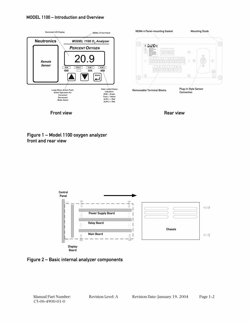
Oversized LED Display
Large Menu-driven Push-button Operators for:
IncrementDecrement
Mode-Select
Color-coded Statusindicators:
RUN = GreenFault = YellowALM-1 = RedALM-2 = Red
NEMA 4 Front Panel
SHOCK.SERVICE BYAUTHORIZEDTECHNICIANONLY.
RISK OFELECTRICAL
NEMA 4 Panel-mounting Gasket
Removeable Terminal Blocks
Mounting Studs
Plug-in Style Sensor Connection
Chassis
Power Supply Board
Relay Board
Main Board
DisplayBoard
ControlPanel
Figure 1 – Model 1100 oxygen analyzer front and rear view
Figure 2 – Basic internal analyzer components
Front view Rear view
System Hardware Overview
Manual Part Number: C5-06-4900-01-0
Revision Level: A Revision Date: January 19, 2004 Page 1-3
1.3 System Hardware Overview
1.3.1 Main Board The main board houses the microprocessor, and supporting electronics for controlling the operation of the Model 1100 Analyzer. The main board receives the sensor input, and provides the control and display functions of the analyzer.
1.3.2 Relay Board The Relay Board houses relay contacts for all of the Alarm and Control features of the 1100. The relays are mapped discretely to each alarm to provide electrical outputs for reporting, and process control use.
1.3.3 Power Supply The power supply board is designed to take 110/220 VAC, 50/60 Hz mains power input. The supply is fused directly on the board. Optional 12 VDC and 24 VDC power supplies are available for installations where a DC voltage is required to power the Model 1100. A 12 VDC battery-backup power input (battery not provided) is also provided to act as an emergency back up in case of mains power failure.
1.3.4 Display Board The Display board is designed to generate a digital indication of the concentration of oxygen (Appendix E – range / output chart), and fault codes (section 4.3.1). The display is a 7-segment, ¾” alphanumeric LED.
1.3.5 Control Panel The Control Panel serves as the main user interface. The Control Panel features the keypad (ramp-UP, ramp-DOWN, and MODE keys) and the status LED’s. The control panel is designed to be splash and water-resistant. There are #8-32 threaded mounting studs at each of the four corners for flush mounting of the model 1100 to a stationary control or equipment panel. The gasketed panel is suitable for NEMA type 4 / IP20 environments when properly installed.
1.3.6 Sensor The sensor is an electrochemical cell, which measures partial pressure of oxygen. Sample gas is passed by the face of the sensor and an electrical output is generated, which is directly proportional and linear to the partial pressure of oxygen in the gas sample. It is similar in operation to a battery, except that one of the reactants, oxygen is supplied externally to the cell.
The CAG-250E Oxygen sensor consists of a lead anode, oxygen cathode, and weak acid electrolyte. Oxygen permeates a plastic membrane on the face of the sensor. The oxygen is electrochemically reduced at the cathode. The current generated is directly proportional to the partial pressure of oxygen at the sensing surface of the cell.
The CAG-250E sensor is a sealed disposable device with a serviceable life of 2 to 3 years. It does not require any periodic maintenance. When the sensor has expired, the entire device is disposed of and replaced easily and safely.
MODEL 1100 – Introduction and Overview
Manual Part Number: C5-06-4900-01-0
Revision Level: A Revision Date: January 19, 2004 Page 1-4
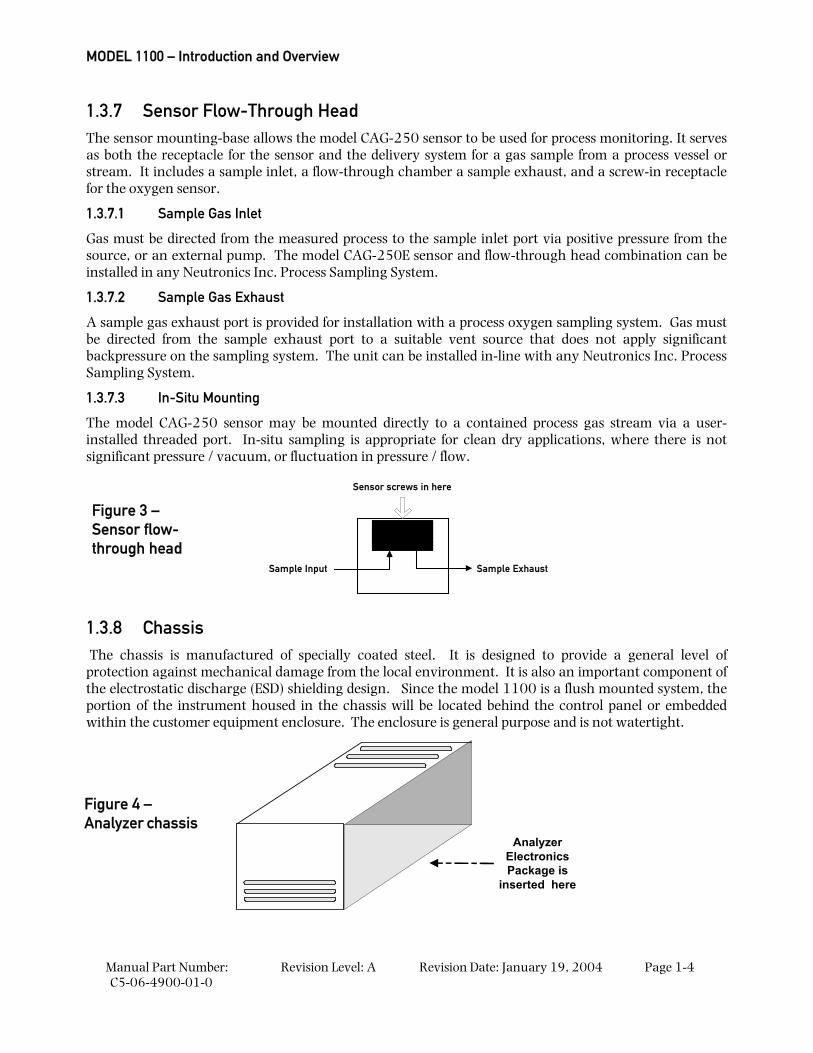
1.3.7 Sensor Flow-Through Head The sensor mounting-base allows the model CAG-250 sensor to be used for process monitoring. It serves as both the receptacle for the sensor and the delivery system for a gas sample from a process vessel or stream. It includes a sample inlet, a flow-through chamber a sample exhaust, and a screw-in receptacle for the oxygen sensor.
1.3.7.1 Sample Gas Inlet
Gas must be directed from the measured process to the sample inlet port via positive pressure from the source, or an external pump. The model CAG-250E sensor and flow-through head combination can be installed in any Neutronics Inc. Process Sampling System.
1.3.7.2 Sample Gas Exhaust
A sample gas exhaust port is provided for installation with a process oxygen sampling system. Gas must be directed from the sample exhaust port to a suitable vent source that does not apply significant backpressure on the sampling system. The unit can be installed in-line with any Neutronics Inc. Process Sampling System.
1.3.7.3 In-Situ Mounting
The model CAG-250 sensor may be mounted directly to a contained process gas stream via a user-installed threaded port. In-situ sampling is appropriate for clean dry applications, where there is not significant pressure / vacuum, or fluctuation in pressure / flow.
Sample ExhaustSample Input
Sensor screws in here
1.3.8 Chassis The chassis is manufactured of specially coated steel. It is designed to provide a general level of protection against mechanical damage from the local environment. It is also an important component of the electrostatic discharge (ESD) shielding design. Since the model 1100 is a flush mounted system, the portion of the instrument housed in the chassis will be located behind the control panel or embedded within the customer equipment enclosure. The enclosure is general purpose and is not watertight.
AnalyzerElectronicsPackage is
inserted here
Figure 4 – Analyzer chassis
Figure 3 – Sensor flow-through head
System Hardware Overview
Manual Part Number: C5-06-4900-01-0
Revision Level: A Revision Date: January 19, 2004 Page 1-5
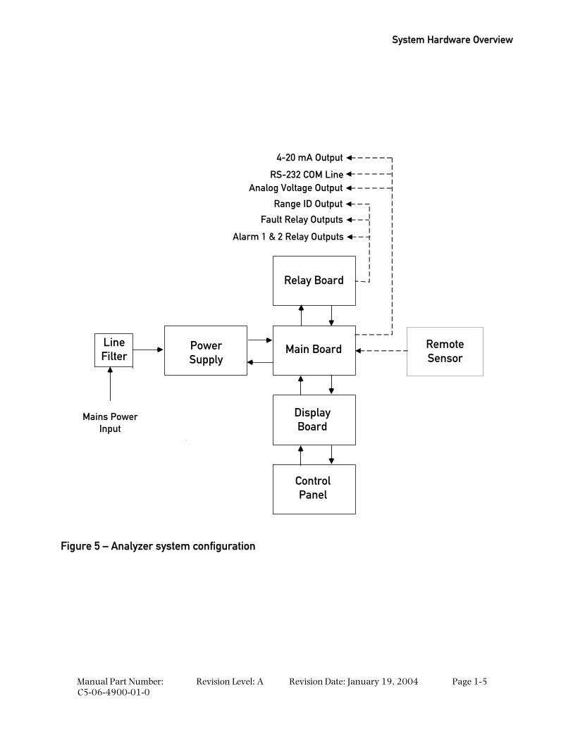
Relay Board
RS-232 COM Line
Mains PowerInput
PowerSupply
Main Board
DisplayBoard
ControlPanel
LineFilter
Fault Relay Outputs
Alarm 1 & 2 Relay Outputs
Range ID Output
Analog Voltage Output
4-20 mA Output
RemoteSensor
Figure 5 – Analyzer system configuration
MODEL 1100 – Introduction and Overview
Manual Part Number: C5-06-4900-01-0
Revision Level: A Revision Date: January 19, 2004 Page 1-6
1.4 Analyzer Inputs and Outputs
1.4.1 The Oxygen Sensor Input The oxygen sensor electrical input to the model 1100 is used to indicate the oxygen concentration measured by the model CAG-250E oxygen sensor. It is proportional to the oxygen present in the measured gas at the sensor membrane. The oxygen sensor input is a female 3-pin 180° DIN connector to mate with the supplied sensor interface cable connector.
1.4.2 Alarm-1 Relay Output The Alarm-1 relay is mapped to the Alarm-1 setpoint, and is provided for process control use. The user may set the oxygen level at which Alarm-1 activates (section 3.2.2). Alarm-1 may be configured as ascending (highest oxygen level allowable) or descending (lowest oxygen level allowable) action. The relay output may be configured for fail-safe (relay coil de-energized in alarm state) or non fail-safe (relay coil energized in alarm state) action. Factory default settings are ascending, and fail-safe (Appendix C, Factory Configuration). The Alarm-1 relay contacts are form C (DPDT), voltage-free.
1.4.3 Alarm-2 Relay Output The Alarm-2 relay is mapped to the Alarm-2 setpoint, and is provided for process control use. The user may set the oxygen level at which Alarm-2 activates (section 3.2.3). Alarm-2 may be configured as ascending (highest oxygen level allowable) or descending (lowest oxygen level allowable) action. The relay output may be configured for fail-safe (relay coil de-energized in alarm state) or non fail-safe (relay coil energized in alarm state) action. Factory default settings are ascending, and fail-safe (Appendix C, Factory Configuration). The Alarm-2 relay contacts are form C (DPDT), voltage-free.
1.4.4 Fault Relay Output The Fault relay output is used to indicate that there is at least one system fault active on the Model 1100 analyzer (section 4.3.1 – fault codes and definitions). The relay output action is non fail-safe, and is not configurable. The Fault relay contacts are Form B (SPST), voltage-free.
1.4.5 Analog Voltage Output The Analog Voltage output is a dynamic potential used to indicate to a remote device the displayed oxygen concentration during normal analyzer operation and system maintenance. The Analog voltage output follows the oxygen readout displayed on the 7-segment LED display during all system and user modes except for user setup. For a complete listing of available output levels by analyzer range, refer to Appendix E – range / output chart.
The Analog voltage range can be adjusted by the user (section 4.1 – system setup). Available settings are 0-VDC for minimum-scale-deflection, to 1, 5 or 10-VDC full-scale. The factory default setting is 0-1 VDC (Appendix C, Factory Configuration). The Analog voltage output is scaled according to the analyzer’s selected range, and must be used in conjunction with the Range ID voltage when the Analyzer is configured for auto-ranging (section 1.4.8).
Control Panel User Interface
Manual Part Number: C5-06-4900-01-0
Revision Level: A Revision Date: January 19, 2004 Page 1-7
1.4.6 Analog Current Output The Analog Current output is a dynamic current flow used to indicate to a remote device the displayed oxygen concentration during normal analyzer operation and system maintenance. The Analog current output follows the oxygen readout displayed on the 7-segment LED display during all system and user modes except for user setup. For a complete listing of output levels by analyzer range, refer to Appendix E – range / output chart.
The minimum scale deflection may be set to either 0 mA or 4 mA. Full-scale is fixed at 20 mA. The Analog current output is scaled according to the analyzer’s selected range, and must be used in conjunction with the Range ID voltage when the Analyzer is configured for auto-ranging (section 1.4.8).
1.4.7 Range ID Output The model 1100 can be configured by the user to automatically switch its measurement range, based on the concentration of oxygen measured while in-service, to provide the most accurate, and highest resolution outputs at all times. For a complete listing of analyzer ranges, refer to Appendix E – range / output chart.
Remote auxiliary devices designed to interpret the model 1100 Analog outputs over multiple output range scales require an indication of the analyzer’s selected range at all times for accurate scaling. The model 1100 features a 0-10 VDC Auto-Range Identification output. The range ID output is used in conjunction with the Analog voltage and Analog current outputs when auto-ranging is used. It provides an indication of the Analog outputs’ selected full-scale. There are five range ID voltage levels used in the 1100 to correspond with its five output ranges (Appendix E – range / output chart).
1.4.8 Service Port The Service port provides a user-friendly means of digital communications with the model 1100 Analyzer. Through this port, the unit may be configured, calibrated, and queried for most functions. The RS-232 port may also be programmed to send out information on a timed basis for users who prefer to use Digital instead of Analog interfacing with the analyzer. In addition, the service port may be used with a PC based computer (such as a portable notebook computer) over a standard bi-directional RS-232 serial interface.
1.5 Control panel User Interface
1.5.1 The “UP” Pushbutton The “UP” pushbutton can be used to program the 1100 Analyzer via the control panel. This momentary push-button soft key is used to enter incremental information. Its function is menu-driven.
1.5.2 The “DOWN” Pushbutton The “DOWN” pushbutton can be used to program the 1100 Analyzer via the control panel. This momentary push-button soft key is used to enter decremental information. Its function is menu-driven.
1.5.3 The “MODE” Pushbutton The “MODE” pushbutton can be used to program the model 1100 via the control panel. This momentary push-button soft key is used to navigate the operational modes available through the control panel. Its function is menu-driven.
MODEL 1100 – Introduction and Overview
Manual Part Number: C5-06-4900-01-0
Revision Level: A Revision Date: January 19, 2004 Page 1-8
1.5.4 7-Segment Alphanumeric Display The 7-Segment alphanumeric display feeds back information from the model 1100 to the user via the control panel. The primary purpose of the 7-Segment display is to show the oxygen concentration readout. It is also used for feedback of operational status, fault codes, and other information necessary to perform system setup and maintenance.
1.5.5 RUN Indicator LED The purpose of the RUN Indicator LED is to inform the user via the control panel that the model 1100 is measuring the concentration of the sample gas and updating the display and outputs accordingly, and has not detected any alarm, or fault conditions.
1.5.6 Alarm-1 Indicator LED The purpose of the Alarm-1 Indicator LED is to inform the user via the control panel that the measured oxygen concentration has exceeded the alarm-1 threshold; alarm-1 and its associated relay are in active mode.
1.5.7 Alarm-2 Indicator LED The purpose of the Alarm-2 Indicator LED is to inform the user via the control panel that the measured oxygen concentration has exceeded the Alarm-2 threshold; alarm-2 and its associated relay are in active mode.
1.5.8 Fault Indicator LED The purpose if the Fault Indicator LED is to inform the user via the control panel that at least one system fault is active. Note that when the fault Indicator LED is active, the fault relay will also be active.
Manual Part Number: C5-06-4900-01-0
Revision Level: A Revision Date: January 19, 2004 Page 2-1
2 CHAPTER 2 – SYSTEM INSTALLATION AND START-UP
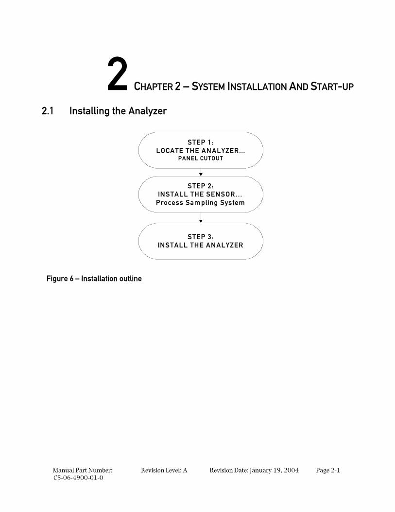
2.1 Installing the Analyzer
STEP 1:LOCATE THE ANALYZER...
PANEL CUTOUT
STEP 2:INSTALL THE SENSOR…
Process Sam pling System
STEP 3:INSTALL THE ANALYZER
Figure 6 – Installation outline
System Installation and Startup
Manual Part Number: C5-06-4900-01-0
Revision Level: A Revision Date: January 19, 2004 Page 2-2
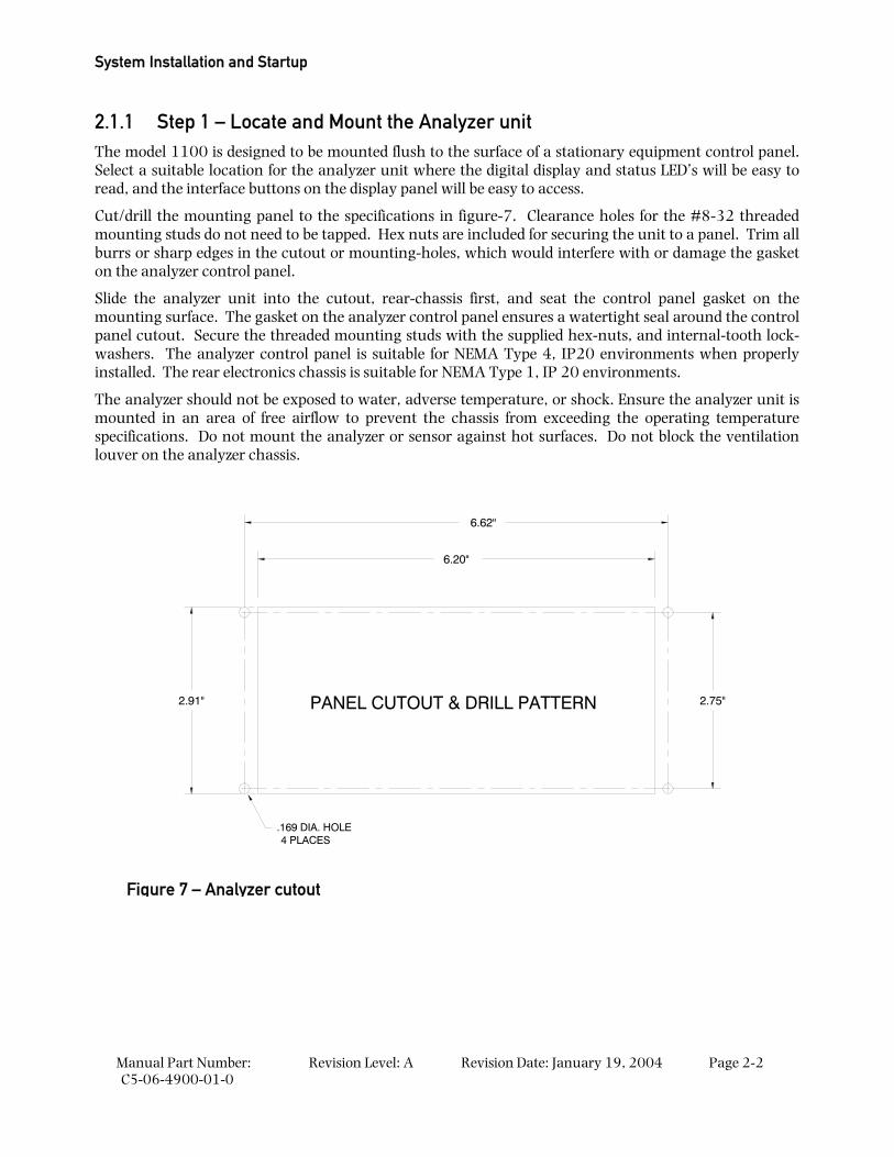
2.1.1 Step 1 – Locate and Mount the Analyzer unit The model 1100 is designed to be mounted flush to the surface of a stationary equipment control panel. Select a suitable location for the analyzer unit where the digital display and status LED’s will be easy to read, and the interface buttons on the display panel will be easy to access.
Cut/drill the mounting panel to the specifications in figure-7. Clearance holes for the #8-32 threaded mounting studs do not need to be tapped. Hex nuts are included for securing the unit to a panel. Trim all burrs or sharp edges in the cutout or mounting-holes, which would interfere with or damage the gasket on the analyzer control panel.
Slide the analyzer unit into the cutout, rear-chassis first, and seat the control panel gasket on the mounting surface. The gasket on the analyzer control panel ensures a watertight seal around the control panel cutout. Secure the threaded mounting studs with the supplied hex-nuts, and internal-tooth lock-washers. The analyzer control panel is suitable for NEMA Type 4, IP20 environments when properly installed. The rear electronics chassis is suitable for NEMA Type 1, IP 20 environments.
The analyzer should not be exposed to water, adverse temperature, or shock. Ensure the analyzer unit is mounted in an area of free airflow to prevent the chassis from exceeding the operating temperature specifications. Do not mount the analyzer or sensor against hot surfaces. Do not block the ventilation louver on the analyzer chassis.
2.91"
6.20"
6.62"
2.75"PANEL CUTOUT & DRILL PATTERN
.169 DIA. HOLE4 PLACES
Figure 7 – Analyzer cutout
Installing the Analyzer
Manual Part Number: C5-06-4900-01-0
Revision Level: A Revision Date: January 19, 2004 Page 2-3
2.1.2 Step 2 – Install the Remote Sensor The model 1100 is supplied with a model CAG-250E oxygen sensor, and sensor flow-through head for connection to a sampled process gas stream, and a sensor interface cable with a rubberized sheath to protect the sensor and the sensor electrical connector from dust and liquid spray.
The model 1100 can also be supplied with a Neutronics Inc. process Sampling system, built-to-application. For detailed instructions on remote sensor installation with a Neutronics Inc. Process Sampling System, please refer to the equipment manual.
CAUTION: The remote mounted sensor contains a weak acid electrolyte (concentrated acetic acid). Do not attempt to disassemble the sensor. Any sensor found leaking electrolyte should be disposed of according to local regulations. See material safety data supplied in the Appendix of this manual. Any damaged sensor should be replaced with a new unit.
2.1.2.1 Flow-through Head
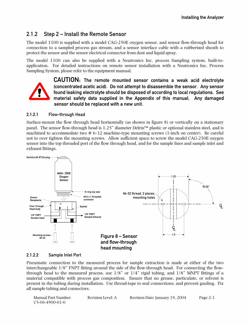
Surface-mount the flow through head horizontally (as shown in figure 8) or vertically on a stationary panel. The sensor flow-through head is 1.25” diameter Delrin plastic or optional stainless steel, and is machined to accommodate two # 6-32 machine-type mounting screws (1-inch on center). Be careful not to over tighten the mounting screws. Allow sufficient space to screw the model CAG-250E oxygen sensor into the top threaded port of the flow through head, and for the sample lines and sample inlet and exhaust fittings.
MAX- 250EOxygenSensor
Flow ThroughHead body
1/8" FNPTSample Exhaust
1/8" FNPTSample Input
Mounting screws -#6-32
Switchcraft #712A plug
M16 x 1 threadedconnector
O-ring top seal
Gasket
SensorReceptacle
2.1.2.2 Sample Inlet Port
Pneumatic connection to the measured process for sample extraction is made at either of the two interchangeable 1/8” FNPT fitting around the side of the flow-through head. For connecting the flow-through head to the measured process, use 1/8” or 1/4” rigid tubing, and 1/8” MNPT fittings of a material compatible with process gas composition. Ensure that no grease, particulate, or solvent is present in the tubing during installation. Use thread-tape to seal connections, and prevent gauling. Fix all sample tubing and connectors.
Figure 8 – Sensor and flow-through head mounting
CL
CL
1.25
1.0
#6-32 thread, 2 places,mounting holes
90.00°
System Installation and Startup
Manual Part Number: C5-06-4900-01-0
Revision Level: A Revision Date: January 19, 2004 Page 2-4
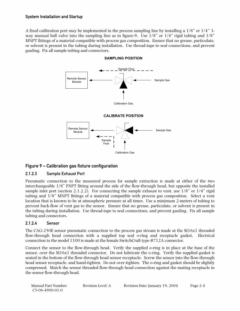
A fixed calibration port may be implemented in the process sampling line by installing a 1/8” or 1/4” 3-way manual ball valve into the sampling line as in figure-9. Use 1/8” or 1/4” rigid tubing and 1/8” MNPT fittings of a material compatible with process gas composition. Ensure that no grease, particulate, or solvent is present in the tubing during installation. Use thread-tape to seal connections, and prevent gauling. Fix all sample tubing and connectors.
Remote SensorModule
Calibration Gas
Sample Gas
Sample Flow
Remote SensorModule
Calibration Gas
Sample Gas
SampleFlow
SAMPLING POSITION
CALIBRATE POSITION
Figure 9 – Calibration gas fixture configuration
2.1.2.3 Sample Exhaust Port
Pneumatic connection to the measured process for sample extraction is made at either of the two interchangeable 1/8” FNPT fitting around the side of the flow-through head, but opposite the installed sample inlet port (section 2.1.2.2). For connecting the sample exhaust to vent, use 1/8” or 1/4” rigid tubing and 1/8” MNPT fittings of a material compatible with process gas composition. Select a vent location that is known to be at atmospheric pressure at all times. Use a minimum 2-meters of tubing to prevent back-flow of vent gas to the sensor. Ensure that no grease, particulate, or solvent is present in the tubing during installation. Use thread-tape to seal connections, and prevent gauling. Fix all sample tubing and connectors.
2.1.2.4 Sensor
The CAG-250E sensor pneumatic connection to the process gas stream is made at the M16x1 threaded flow-through head connection with a supplied top seal o-ring and receptacle gasket. Electrical connection to the model 1100 is made at the female SwitchCraft type #712A connector.
Connect the sensor to the flow-through head. Verify the supplied o-ring is in place at the base of the sensor, over the M16x1 threaded connector. Do not lubricate the o-ring. Verify the supplied gasket is seated in the bottom of the flow-through head sensor receptacle. Screw the sensor into the flow-through head sensor receptacle, and hand-tighten. Do not over-tighten. The o-ring and gasket should be slightly compressed. Match the sensor threaded flow-through head connection against the mating receptacle in the sensor flow-through head.
Installing the Analyzer
Manual Part Number: C5-06-4900-01-0
Revision Level: A Revision Date: January 19, 2004 Page 2-5
Attach the supplied sensor cable to the model CAG-250 oxygen sensor using the female SwitchCraft type #712A connector. Hand-tighten the capture-ring to secure the connection. Match the sensor electrical connection against the mating connector on the sensor interface cable. Slide the protective sheath over the sensor. Fix all wiring and connectors.
Sampled process gas may be applied to the sensor flow-through head any time after the sensor is attached to the flow-through head. Regulate sample gas to 1 to 3 psig at 1-SLPM flow rate. Do not exceed 3-psig at the sample inlet port. Never apply an unregulated gas source to the sensor flow-through head.
2.1.3 Step 3 – Install the Analyzer
DANGER: Electrical connections on the rear of the Model 1100 Oxygen analyzer may have hazardous voltages present once power has been applied to the unit. High voltages may remain present for a short time even after power has been disconnected from the analyzer. Take care in observing standard electrical practices when making electrical connections to the Model 1100 Oxygen analyzer.
DANGER: The model 1100 analyzer is not rated intrinsically safe or explosion proof. Be certain that no flammable gases are present in the area where the Model 1100 analyzer will be installed.
CAUTION: The model 1100 housing is not rated waterproof. Do not mount the analyzer or the sensor in an area where it may contact water or other liquid elements.
WARNING: Be certain that all power is OFF to the analyzer and associated wiring (cables) before attempting installation. DO NOT WORK WITH LIVE WIRES! Do not leave any exposed wire at the terminal blocks. Before applying power, ensure terminal blocks are fully inserted into the mating connector at the analyzer.
System Installation and Startup
Manual Part Number: C5-06-4900-01-0
Revision Level: A Revision Date: January 19, 2004 Page 2-6
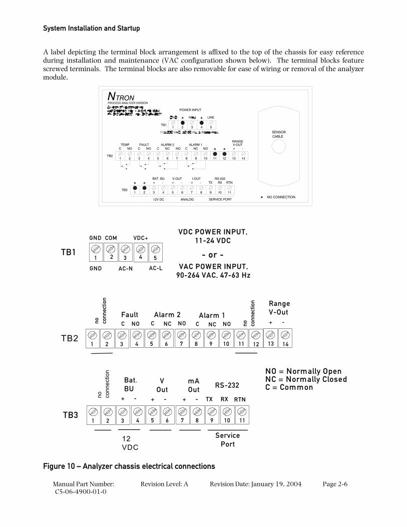
A label depicting the terminal block arrangement is affixed to the top of the chassis for easy reference during installation and maintenance (VAC configuration shown below). The terminal blocks feature screwed terminals. The terminal blocks are also removable for ease of wiring or removal of the analyzer module.
111097 8654321
SERVICE PORTANALOG12V DCNO CONNECTION*
PROCESS ANALYZER DIVISION
TB3
*
TB2
NOC
1 2
TEMP
NTRON
RTNBAT. BU
* +V-OUT
- + -
CNOC
43 5
FAULTNONC
6 7
ALARM 2
I-OUT+ -
RS-232TX RX
NO
10
NCC
8 9
ALARM 1
**
11 12
2
*
POWER INPUT
TB11
*
3 4 5
LINE
CABLE
-+
13 14
V-OUTRANGE
SENSOR
1 2 3
no conn
ectio
n
TB24 5 6 7 8 9 10 11 12 13 14
FaultC NO
Alarm 1C NC NO
Alarm 2C NC NO
RangeV-Out+ -
1 2 3TB3
4 5 6 7 8 9 10 11
Bat.BU
+ -
VOut
+ -
mAOut
+ -
RS-232
TX RX RTN
12VDC
no conn
ectio
n
no conn
ectio
n
ServicePort
NO = Normally OpenNC = Normally ClosedC = Common
VAC POWER INPUT,90-264 VAC, 47-63 Hz
VDC POWER INPUT,11-24 VDC
1 3
GND
5
VDC+
2 4
COM
GND AC-N AC-L
- or -TB1
Figure 10 – Analyzer chassis electrical connections
Installing the Analyzer
Manual Part Number: C5-06-4900-01-0
Revision Level: A Revision Date: January 19, 2004 Page 2-7
2.1.3.1 Sensor Input
Electrical connection to the model CAG-250E oxygen sensor is made by connecting the supplied sensor interface cable between the analyzer and the sensor. Attach the sensor interface cable to the model 1100 analyzer female 180° 3-pin DIN cable connector. Match the sensor input connector against the mating connector on the sensor interface cable. Fix all wiring and connectors.
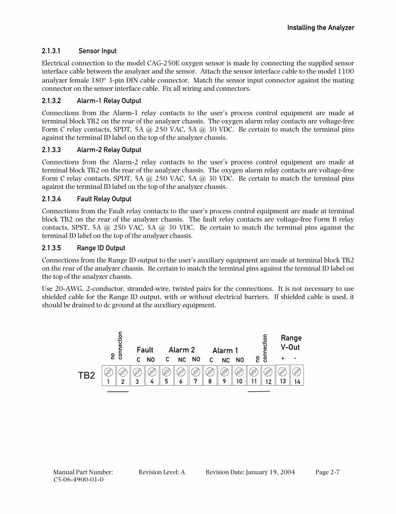
2.1.3.2 Alarm-1 Relay Output
Connections from the Alarm-1 relay contacts to the user’s process control equipment are made at terminal block TB2 on the rear of the analyzer chassis. The oxygen alarm relay contacts are voltage-free Form C relay contacts, SPDT, 5A @ 250 VAC, 5A @ 30 VDC. Be certain to match the terminal pins against the terminal ID label on the top of the analyzer chassis.
2.1.3.3 Alarm-2 Relay Output
Connections from the Alarm-2 relay contacts to the user’s process control equipment are made at terminal block TB2 on the rear of the analyzer chassis. The oxygen alarm relay contacts are voltage-free Form C relay contacts, SPDT, 5A @ 250 VAC, 5A @ 30 VDC. Be certain to match the terminal pins against the terminal ID label on the top of the analyzer chassis.
2.1.3.4 Fault Relay Output
Connections from the Fault relay contacts to the user’s process control equipment are made at terminal block TB2 on the rear of the analyzer chassis. The fault relay contacts are voltage-free Form B relay contacts, SPST, 5A @ 250 VAC, 5A @ 30 VDC. Be certain to match the terminal pins against the terminal ID label on the top of the analyzer chassis.
2.1.3.5 Range ID Output
Connections from the Range ID output to the user’s auxiliary equipment are made at terminal block TB2 on the rear of the analyzer chassis. Be certain to match the terminal pins against the terminal ID label on the top of the analyzer chassis.
Use 20-AWG, 2-conductor, stranded-wire, twisted pairs for the connections. It is not necessary to use shielded cable for the Range ID output, with or without electrical barriers. If shielded cable is used, it should be drained to dc ground at the auxiliary equipment.
1 2 3
no conn
ectio
n
TB24 5 6 7 8 9 10 11 12 13 14
FaultC NO
Alarm 1C NC NO
Alarm 2C NC NO
RangeV-Out+ -no co
nnec
tion
System Installation and Startup
Manual Part Number: C5-06-4900-01-0
Revision Level: A Revision Date: January 19, 2004 Page 2-8
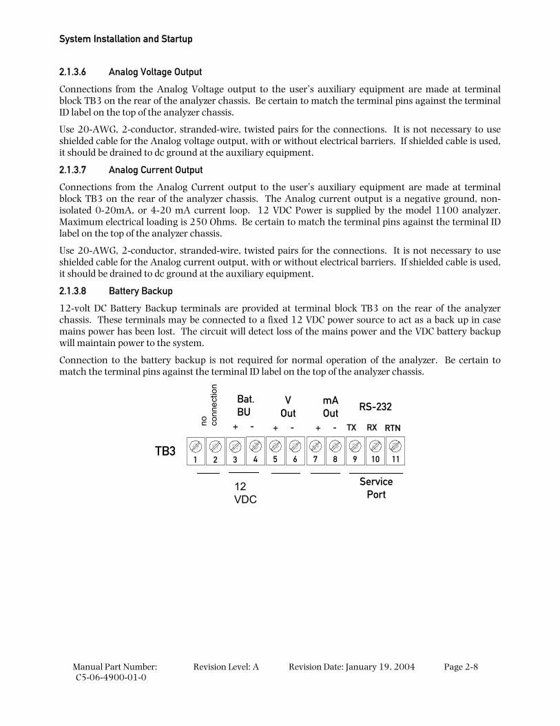
2.1.3.6 Analog Voltage Output
Connections from the Analog Voltage output to the user’s auxiliary equipment are made at terminal block TB3 on the rear of the analyzer chassis. Be certain to match the terminal pins against the terminal ID label on the top of the analyzer chassis.
Use 20-AWG, 2-conductor, stranded-wire, twisted pairs for the connections. It is not necessary to use shielded cable for the Analog voltage output, with or without electrical barriers. If shielded cable is used, it should be drained to dc ground at the auxiliary equipment.
2.1.3.7 Analog Current Output
Connections from the Analog Current output to the user’s auxiliary equipment are made at terminal block TB3 on the rear of the analyzer chassis. The Analog current output is a negative ground, non-isolated 0-20mA, or 4-20 mA current loop. 12 VDC Power is supplied by the model 1100 analyzer. Maximum electrical loading is 250 Ohms. Be certain to match the terminal pins against the terminal ID label on the top of the analyzer chassis.
Use 20-AWG, 2-conductor, stranded-wire, twisted pairs for the connections. It is not necessary to use shielded cable for the Analog current output, with or without electrical barriers. If shielded cable is used, it should be drained to dc ground at the auxiliary equipment.
2.1.3.8 Battery Backup
12-volt DC Battery Backup terminals are provided at terminal block TB3 on the rear of the analyzer chassis. These terminals may be connected to a fixed 12 VDC power source to act as a back up in case mains power has been lost. The circuit will detect loss of the mains power and the VDC battery backup will maintain power to the system.
Connection to the battery backup is not required for normal operation of the analyzer. Be certain to match the terminal pins against the terminal ID label on the top of the analyzer chassis.
1 2 3TB3
4 5 6 7 8 9 10 11
Bat.BU
+ -
VOut
+ -
mAOut
+ -
RS-232
TX RX RTN
12VDC
no conn
ectio
n
ServicePort
Installing the Analyzer
Manual Part Number: C5-06-4900-01-0
Revision Level: A Revision Date: January 19, 2004 Page 2-9
2.1.3.9 RS-232 Service Port
Connections from the Range ID output to the user’s auxiliary equipment are made at terminal block TB3 on the rear of the analyzer chassis. Be certain to match the terminal pins against the terminal ID label on the top of the analyzer chassis.
For interfacing with any standard PC computer via serial port, use 20-AWG, 3-conductor, shielded, stranded-wire, jacketed cable, terminated on one end with a female DB9 connector. The shielding should be drained to dc ground at the computer.
SIGNAL DESIGNATION AT ANALYZER
ANALYZER TB2 CONNECTION
SIGNAL DESIGNATION AT COMPUTER
COMPUTER DB9 SERIAL PORT CONNECTION
RX Pin 9 TX Pin 2 TX Pin 10 RX Pin 3 RTN Pin 11 RTN Pin 5
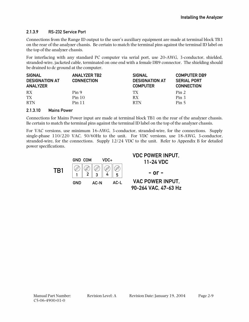
2.1.3.10 Mains Power
Connections for Mains Power input are made at terminal block TB1 on the rear of the analyzer chassis. Be certain to match the terminal pins against the terminal ID label on the top of the analyzer chassis.
For VAC versions, use minimum 16-AWG, 3-conductor, stranded-wire, for the connections. Supply single-phase 110/220 VAC, 50/60Hz to the unit. For VDC versions, use 18-AWG, 3-conductor, stranded-wire, for the connections. Supply 12/24 VDC to the unit. Refer to Appendix B for detailed power specifications.
VAC POWER INPUT,90-264 VAC, 47-63 Hz
VDC POWER INPUT,11-24 VDC
1 3
GND
5
VDC+
2 4
COM
GND AC-N AC-L
- or -TB1
System Installation and Startup
Manual Part Number: C5-06-4900-01-0
Revision Level: A Revision Date: January 19, 2004 Page 2-10
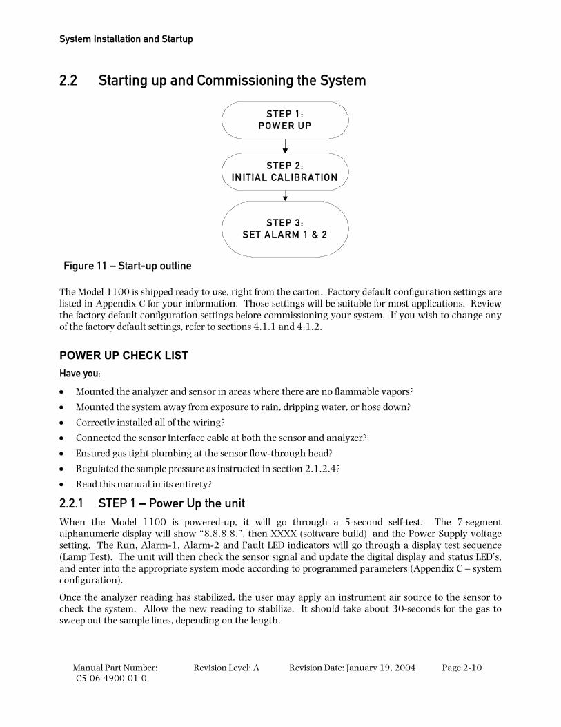
2.2 Starting up and Commissioning the System
STEP 1:POW ER UP
STEP 2:IN ITIAL CALIBRATION
STEP 3:SET ALARM 1 & 2
The Model 1100 is shipped ready to use, right from the carton. Factory default configuration settings are listed in Appendix C for your information. Those settings will be suitable for most applications. Review the factory default configuration settings before commissioning your system. If you wish to change any of the factory default settings, refer to sections 4.1.1 and 4.1.2.
POWER UP CHECK LIST Have you:
• Mounted the analyzer and sensor in areas where there are no flammable vapors?
• Mounted the system away from exposure to rain, dripping water, or hose down?
• Correctly installed all of the wiring?
• Connected the sensor interface cable at both the sensor and analyzer?
• Ensured gas tight plumbing at the sensor flow-through head?
• Regulated the sample pressure as instructed in section 2.1.2.4?
• Read this manual in its entirety?
2.2.1 STEP 1 – Power Up the unit When the Model 1100 is powered-up, it will go through a 5-second self-test. The 7-segment alphanumeric display will show “8.8.8.8.”, then XXXX (software build), and the Power Supply voltage setting. The Run, Alarm-1, Alarm-2 and Fault LED indicators will go through a display test sequence (Lamp Test). The unit will then check the sensor signal and update the digital display and status LED’s, and enter into the appropriate system mode according to programmed parameters (Appendix C – system configuration).
Once the analyzer reading has stabilized, the user may apply an instrument air source to the sensor to check the system. Allow the new reading to stabilize. It should take about 30-seconds for the gas to sweep out the sample lines, depending on the length.
Figure 11 – Start-up outline
Starting up and Commissioning the System
Manual Part Number: C5-06-4900-01-0
Revision Level: A Revision Date: January 19, 2004 Page 2-11
2.2.2 STEP 2 – Calibrate the Unit All units are calibrated at the Neutronics factory before shipping. However, it is recommended that the model 1100 be calibrated at commissioning, under ambient and process conditions similar to those encountered while in-service. Refer to section 3.2.1 for detailed analyzer calibration instructions.
Helpful hint The model 1100 is configured-to-order, as specified by the user per the application. If the application has changed, some adjustments in the system configuration may be necessary to optimize the model 1100 performance for the application. After reviewing the calibration instructions, review Appendix C – Factory Configuration Settings. Verify that the current settings are suitable for the application. Refer to Appendices E and F for all valid range and output settings available on the model 1100. If any changes are necessary, they can be performed via the control panel (section 4.1.1) or the service port (section 4.1.2).
2.2.3 STEP 3 –Set Alarm-1 and Alarm-2 After the unit has been calibrated on a known gas source, set the alarm points according to process control requirements. Refer to Appendix C for factory settings.
2.2.3.1 Set Alarm-1
For process control applications, alarm-1 is used normally as the “primary” oxygen-level alarm, and is set to the highest or lowest level of oxygen allowable in your process, according to the application. Refer to section 3.2.2 for information about setting the alarm-1 level.
2.2.3.2 Set Alarm-2
For process control applications, alarm-2 is used normally as the “secondary”, or “warning” oxygen-level alarm, and is set just below to the highest, or just above the lowest level of oxygen allowable in your process, according to the application. Refer to section 3.2.3 for information about setting the alarm-2 level.
The Model 1100 should now be ready for commissioning. Neutronics Inc. offers commissioning, and Factory Acceptance Testing services by our qualified technicians. You may contact the Neutronics factory toll-free at (800) 278-2287 in the continental United States. Elsewhere, call (610) 524-8800) and ask an Ntron Division Service Technician to schedule a service call.

Manual Part Number: C5-06-4900-01-0
Revision Level: A Revision Date: January 19, 2004 Page 3-1
3 CHAPTER 3 – ANALYZER OPERATION
3.1 System Organization The Model 1100 has two types of operational modes – User-type, and System-type. User modes are initiated and controlled by the user, and are used to setup and maintain the analyzer. The User modes are: Calibration, Set/View Alarm-1, Set/View Alarm-2, View Active Faults, and Setup. Operating modes are accessed automatically by the Model 1100 during normal operation, according to its programming, and its configuration parameters. The Operating modes are: Self-Test & Warm-up, Run, Alarm-1 Active, Alarm-2 Active, and Fault Active.
3.2 USER Modes At any time, the user can initiate any of the user modes either from the control panel or through the service port. Control panel access of the Calibration, Set/View Alarm-1, Set/View Alarm-2 and View Active Faults modes will be covered in this chapter. System setup mode and user access via the service port will be covered in section 4.1.
The user modes Calibration, Set/View Alarm-1, Set/View Alarm-2 and View Active Faults are accessed serially via the control panel, in the aforementioned order by repeatedly pressing and releasing the “MODE” key. When a user mode is accessed via the control panel, the model 1100 aborts any system mode active, and holds the state of Alarm-1, Alarm-2, Fault, and Heater OK relay outputs until the user returns the unit to Run mode.
3.2.1 CALIBRATE Mode & Calibration Procedure Calibration mode allows the oxygen sensor and analyzer to be aligned to gases of known oxygen concentration for the most accurate on-line readings. For best accuracy in most ranges, the model 1100 requires single-gas calibration with ambient-level oxygen (20.9 %) at system commissioning, and at regular monthly intervals during the normal service life of the oxygen sensor (2-3 years). The simple procedure requires the user only to apply gas, and adjust the reading on the analyzer control panel. The model 1100 does the rest.
When a new sensor is put into service, the analyzer is calibrated with two gases, 20.9 % and 1 – 4 %, to ensure full range accuracy throughout the normal service life of the sensor. The analyzer will recognize the two calibration gases automatically. The user just applies gas, adjusts the reading on the analyzer control panel, and repeats the same simple steps with another gas. The model 1100 automatically sets up the new sensor for best accuracy throughout its service life.
Calibration should be performed at the following times:
• During commissioning 1
• Once per 30-days of normal operation 1
• When replacing an oxygen sensor 2
• As required while troubleshooting the system 1 1 Single gas calibration 20.9 % O2
2 Two-gas calibration 20.9 % and 1 – 4 % O2
Analyzer Operation
Manual Part Number: C5-06-4900-01-0
Revision Level: A Revision Date: January 19, 2004 Page 3-2
3.2.1.1 Step-1; Select Calibration gases
The following calibration gas sources can be used to calibrate the model 1100:
For normal calibration – use Instrument grade compressed air (Dew-point < 35°, particulates < 3-micron, condensable hydrocarbons < 1-part-per-million), or Certified Standard grade bottled gas at 20.9 % oxygen concentration.
Additional gas for new sensor – use Certified Standard grade bottled calibration gas – 1.5 % O2
WARNING Do not calibrate the model 1100 on zero gas. If the unit is calibrated on zero-gas, it will not operate properly.
3.2.1.2 Step-2; Remove the Oxygen Sensor from Online Service
The oxygen sensor requires removal from on-line service to perform calibration. Calibration or other maintenance of the model 1100 analyzer and sensor should be performed when the measured process is not operating. If the unit has been installed with a Neutronics Inc process sampling system, please refer to the equipment manual for detailed instructions.
Warning Before opening any part of the sampling system to air, make sure that the sampling lines are not pressurized, and are clear of any gas that may create a personnel or environmental hazard.
Disconnect the measured process from the sensor by completely removing the installed 1/8” MNPT fittings from the sensor flow-through head sample inlet port (this step is not necessary if using a fixed gas manifold – section 2.3.1). If it is necessary to exhaust to an alternate path during calibration, completely remove the installed 1/8” MNPT fittings from the sensor flow-through head sample exhaust port. Connect the oxygen sensor to an alternate exhaust location as in section 2.1.2.3.
3.2.1.3 Step-3; Normal Calibration – Apply calibration gas to the Oxygen Sensor
Attach a calibration gas source at 20.9 % oxygen concentration to the model 1100 sensor flow through head. The user may attach the regulated gas source to the sensor head sample inlet port directly, or through a fixed gas manifold. The latter method will help to prevent premature wear of tube-ends and fittings, and increase long-term sampling system integrity. Where a calibration manifold has not been installed, connect the calibration gas source to the oxygen sensor similar to section 2.1.2.2.
Apply calibration gas to the oxygen sensor. Adjust the regulated calibration gas pressure to match the pressure of the in-service sample gas, within the sensor pressure specification of 1-10psig (Appendix B). Be sure to flow calibration gas to the sensor until the analyzer display has stabilized to allow calibration gas to sweep out the sample lines.
Warning: Never apply an unregulated gas supply to the oxygen sensor. High or uncontrolled pressures may damage the oxygen sensor, and/or sampling system components.
USER Modes
Manual Part Number: C5-06-4900-01-0
Revision Level: A Revision Date: January 19, 2004 Page 3-3
3.2.1.4 Step-4; Normal Calibration – Calibrate the Model 1100
After a regulated stream of calibration gas has been applied to the sensor, press and release the “MODE” key once. The 7-segment alphanumeric display will show “CAL”, then an oxygen concentration value. Adjust the displayed oxygen concentration value to read “20.9” by pressing the “UP” or “DOWN” arrow key as required. Press and release the “MODE” key four times to return to Run mode.
Note For normal monthly sensor calibration, skip to step-7, section 3.2.1.8 “Return the Oxygen Sensor to Online Service”. The normal calibration procedure is complete. When replacing the oxygen sensor, the model 1100 must be calibrated to an additional gas 1.5 % oxygen. Continue on to Step-5, section 3.2.1.6 “New Sensor Calibration”.
3.2.1.5 Step-5; New Sensor Calibration – Apply calibration gas to the Oxygen Sensor
Attach a calibration gas source at 1.5 % oxygen concentration to the model 1100 sensor flow through head. The user may attach the regulated gas source to the sensor head sample inlet directly, or through a fixed gas manifold (section 2.3.1). The latter method will help to prevent premature wear of tube-ends and fittings, and increase long-term sampling system integrity. Where a calibration manifold has not been installed, connect the calibration gas source to the oxygen sensor similar to section 2.1.2.2.
Apply calibration gas to the oxygen sensor. Adjust the regulated calibration gas pressure to match the pressure of the in-service sample gas, within the sensor pressure specification of 1-10psig (Appendix B). Be sure to flow calibration gas to the sensor until the analyzer display has stabilized to allow calibration gas to sweep out the sample lines.
Warning: Never apply an unregulated gas supply to the oxygen sensor. High or uncontrolled pressures may damage the oxygen sensor, and/or sampling system components.
3.2.1.6 Step-6; New Sensor Calibration – Calibrate the Model 1100
After a regulated stream of calibration gas has been applied to the sensor, press and release the “MODE” key once. The 7-segment alphanumeric display will show “CAL”, then an oxygen concentration value. Adjust the displayed oxygen concentration to read “1.5” by pressing the “UP” or “DOWN” arrow key as required. Press and release the “MODE” key four times to return to Run mode.
3.2.1.7 Step-7; Return the Oxygen Sensor to Online Service
When calibration procedures are complete, the model 1100 is ready to return to service. Disconnect calibration gas from the oxygen sensor by completely removing the installed 1/8” FNPT fitting from the sensor flow-through head sample inlet port. Where a calibration manifold has not been installed, reconnect the sample inlet port to the process for in-service oxygen measurement (section 2.1.2.2). If an alternate vent connection has been made, reconnect the sensor flow-through head sample exhaust port to the primary vent source (section 2.1.2.3). Be sure to flow sample gas to the sensor until the analyzer display has stabilized to allow time to sweep the sample lines clear of calibration gas.
3.2.2 SET/VIEW ALARM-1 Mode To enter Set Alarm-1 mode from run mode using the keypad; scroll through the user mode menu by pressing momentarily the “MODE” key two (2) times, until the 7-segment alphanumeric display reads “AL1” (set alarm-1 level), and the “RUN” and “ALM1” indicator LED’s flash. The display will show momentarily “AL1” and then the current alarm-1 threshold level (an O2 concentration). Use the “UP” and “DOWN” keys to adjust the alarm-1 setpoint level. Changed settings are automatically saved when the “MODE” key is pressed to enter the next mode.
Analyzer Operation
Manual Part Number: C5-06-4900-01-0
Revision Level: A Revision Date: January 19, 2004 Page 3-4
3.2.3 SET/VIEW ALARM-2 Mode To enter Set Alarm-2 mode from run mode using the keypad; scroll through the user mode menu by pressing momentarily the “MODE” key three (3) times, until the 7-segment alphanumeric display reads “AL2” (set alarm-2 level) and the “RUN” and “ALM2” indicator LED’s flash. The display will show momentarily “AL2” and then the current alarm-2 threshold level (an O2 concentration). Use the “UP” and “DOWN” keys to adjust the alarm-2 setpoint level. Changed settings are automatically saved when the “MODE” key is pressed to enter the next mode.
3.2.4 VIEW ACTIVE FAULTS Mode To enter View Active Faults mode from run mode using the keypad; scroll through the user mode menu by pressing momentarily the “MODE” key four (4) times until the 7-segment alphanumeric display reads “FL”, and the “RUN” and “FAULT” indicator LED’s flash. The display will show momentarily “FL” and then the highest priority active system fault. Press and release the “UP” or “DOWN key to scroll through all active system faults. Refer to section 4.3.1 for a complete fault code listing, and troubleshooting guide. To exit, press and release the “MODE” key.
3.2.5 Return to RUN Mode To exit to run mode from any user mode, using the keypad; scroll through the control panel user mode menu by pressing repeatedly the “MODE” key until the 7-segment alphanumeric display shows ”run”. The display will then show an oxygen concentration. The “RUN”, “ALM1”, “ALM2”, and “FAULT” LED’s will flash for 120 seconds to indicate that the analyzer is in a stabilization period. This is to allow time to sweep the sample lines with sample gas before returning the unit to on-line service. During the stabilization period, alarm-1, alarm-2, and fault, relays remain inactive, and held to their last state before the control panel user mode menu was accessed.
3.3 System Modes The model 1100 has five System modes – Self-Test & warm-up, Run, Alarm-1 Active, Alarm-2 Active, or Fault Active. Self-test & warm-up are fixed routines that are initiated upon each start-up. The remaining system modes, provided no valid manual input is received at the control panel or service port, are initiated automatically by the analyzer according to setup parameters entered by the user in setup mode, compared against monitored inputs and other monitored system hardware in real time.
3.3.1 Self-Test & Warm-up Mode When the model 1100 is started up, it enters into Self-Test & Warm-up mode automatically (section 2.2.1). When the analyzer self-test is complete, the unit checks the current sensor signal, updates the 7-segment LED display, status LED’s, and Analog outputs, then enters into the appropriate system mode according to its programmed parameters.
3.3.2 RUN Mode The model 1100 initiates Run mode when it is continuously measuring the oxygen concentration of the in-service sample gas, and updating the display and outputs accordingly, and it has not detected any valid user input. A solid lit or flashing “RUN” indicator LED indicates to the user that the instrument is on-line, and the system is operating properly.
SYSTEM Modes
Manual Part Number: C5-06-4900-01-0
Revision Level: A Revision Date: January 19, 2004 Page 3-5
When the measured process oxygen concentration falls outside of programmed alarm parameters, and/or the system experiences a fault condition, the model 1100 analyzer enters into Alarm-1 Active, Alarm-2 Active, and/or Fault Active mode accordingly. The system does not abort Run mode, and the “RUN” indicator LED stays lit. The appropriate indicator LED will light in addition to the “RUN” indicator LED.
When programmed alarm setpoints and/or fault conditions are cleared, the model 1100 analyzer aborts Alarm-1 Active, Alarm-2 Active, and/or Fault Active mode accordingly. The system does not abort Run mode, and the “RUN” indicator LED stays lit. Indicator LED’s mapped to aborted modes go out.
When the model 1100 analyzer detects valid user-input, it enters into one of the user modes accordingly – Calibration, Set/View Alarm-1, Set/View Alarm-2, View Active Faults, or User Setup. The analyzer aborts Run mode and holds the state of Alarm-1, Alarm-2, and Fault. The “RUN” indicator LED goes out, except in Calibrate mode, where it flashes.
When the user manually aborts all user modes by returning the system to Run mode, or no valid user input is detected for 120-seconds, the model 1100 checks the current sensor signal, updates the 7-segment LED display, status LED’s, and Analog outputs, then enters into the appropriate system mode according to its programmed parameters. Alarm-1, Alarm-2, and Fault relay outputs are released and the “RUN” indicator LED is lit.
3.3.3 ALARM-1 ACTIVE Mode The model 1100 initiates Alarm-1 Active mode when it has detected that the measured oxygen concentration has exceed the set threshold value of Alarm-1 (section 3.2.2). The “ALM1” indicator LED will light, The “RUN” indicator LED will remain lit. The Alarm-1 relay will change state according to the analyzer configuration (Appendix C, Factory Setup). The Alarm status will be cleared automatically when the measured oxygen concentration is within the set threshold value of Alarm-1. The “ALM1” indicator LED will go out, and the Alarm-1 relay will return to its non-active state according to the analyzer configuration. The Alarm-1 Active mode held to its last state during manual access to the user mode menu.
3.3.4 ALARM-2 ACTIVE Mode The model 1100 initiates Alarm-2 Active mode when it has detected that the measured oxygen concentration has exceed the set threshold value of Alarm-2 (section 3.2.3). The “ALM2” indicator LED will light, The “RUN” indicator LED will remain lit. The Alarm-2 relay will change state according to the analyzer configuration (Appendix C, Factory Setup). The Alarm status will be cleared automatically when the measured oxygen concentration is within the set threshold value of Alarm-2. The “ALM2” indicator LED will go out, and the Alarm-2 relay will return to its non-active state according to the analyzer configuration. The Alarm-2 Active mode is held to its last state during manual access to the user mode menu.
3.3.5 FAULT ACTIVE Mode The model 1100 initiates Fault Active mode when it has detected that one or more Fault criterion have been satisfied (section 4.3.1). The “FAULT” indicator LED will light and the Fault relay will change state. The Fault status will be cleared automatically when no Fault criterion have been satisfied. The “FAULT” indicator LED will go out and the Fault relay will return to its non-active state. The user may view active faults at any time from the control panel (section 3.2.4).

Manual Part Number: C5-06-4900-01-0
Revision Level: A Revision Date: January 19, 2004 Page 4-1
4 CHAPTER 4 – MAINTENANCE AND TROUBLESHOOTING
4.1 System Setup The model 1100 is shipped ready to install and operate with complete factory configuration already programmed and tested. The user may however wish to change the system configuration to suit the application of the analyzer. Some setup parameters may be changed by the user via the control panel keypad. All configuration parameters may be changed by the user via the Service Port.
Important: Before changing any of the model 1100 settings, refer to Appendix C – Factory Setup for reference. If the user has any questions before proceeding with changing analyzer settings, please contact the Neutronics Ntron division Service Department for assistance.
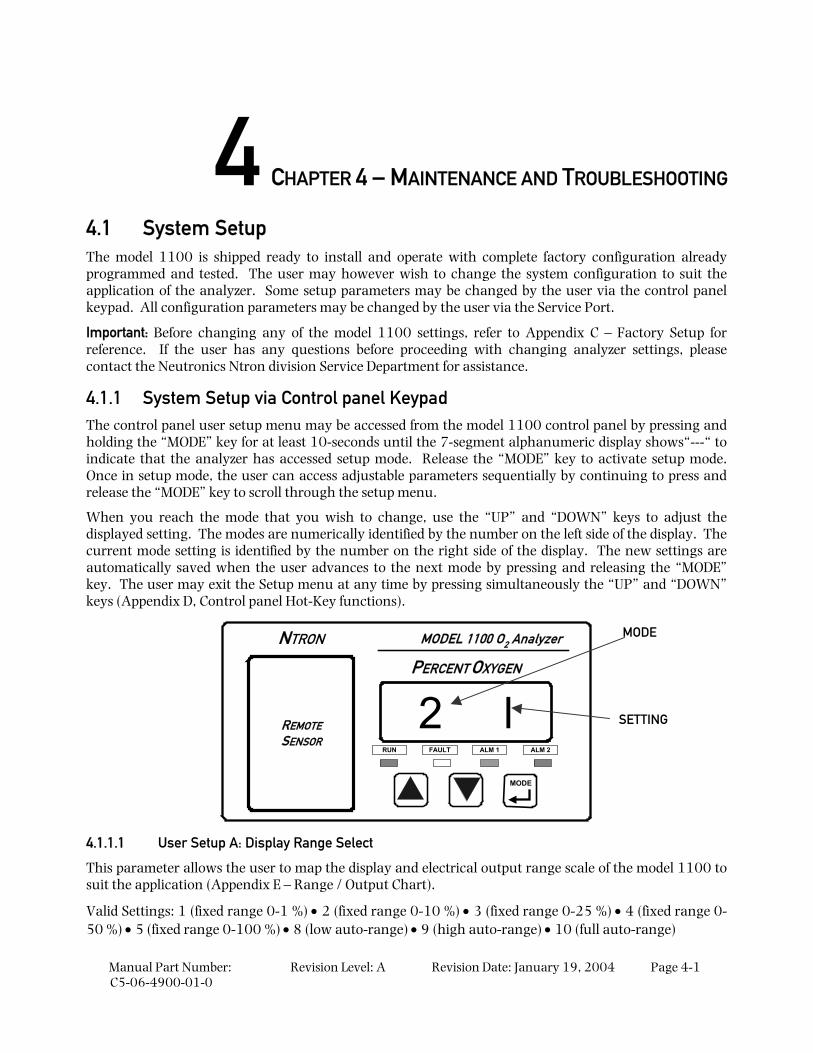
4.1.1 System Setup via Control panel Keypad The control panel user setup menu may be accessed from the model 1100 control panel by pressing and holding the “MODE” key for at least 10-seconds until the 7-segment alphanumeric display shows“---“ to indicate that the analyzer has accessed setup mode. Release the “MODE” key to activate setup mode. Once in setup mode, the user can access adjustable parameters sequentially by continuing to press and release the “MODE” key to scroll through the setup menu.
When you reach the mode that you wish to change, use the “UP” and “DOWN” keys to adjust the displayed setting. The modes are numerically identified by the number on the left side of the display. The current mode setting is identified by the number on the right side of the display. The new settings are automatically saved when the user advances to the next mode by pressing and releasing the “MODE” key. The user may exit the Setup menu at any time by pressing simultaneously the “UP” and “DOWN” keys (Appendix D, Control panel Hot-Key functions).
REMOTESENSOR
MODE
RUN FAULT ALM 1 ALM 2
2 lPERCENT OXYGEN
MODEL 1100 O2 AnalyzerNTRON
4.1.1.1 User Setup A: Display Range Select
This parameter allows the user to map the display and electrical output range scale of the model 1100 to suit the application (Appendix E – Range / Output Chart).
Valid Settings: 1 (fixed range 0-1 %) • 2 (fixed range 0-10 %) • 3 (fixed range 0-25 %) • 4 (fixed range 0-50 %) • 5 (fixed range 0-100 %) • 8 (low auto-range) • 9 (high auto-range) • 10 (full auto-range)
MODE
SETTING
Maintenance and Troubleshooting
Manual Part Number: C5-06-4900-01-0
Revision Level: A Revision Date: January 19, 2004 Page 4-2
4.1.1.2 User Setup 1: Alarm-1 Relays Ascending/Descending Action
This parameter allows the user to set the Alarm-1 relay action to ascending (the relay is set to its active state when the oxygen level is above the Alarm-1 level set point) or to descending (the relay is set to its active state when the oxygen level is below the Alarm-1 level set point).
Valid Settings: 0 (Descending) • 1 (Ascending)
4.1.1.3 User Setup 2: Alarm-2 Relays Ascending/Descending Action
This parameter allows the user to set the Alarm-2 relay action to ascending (the relay is set to its active state when the oxygen level is above the Alarm-2 level set point) or to descending (the relay is set to its active state when the oxygen level is below the Alarm-2 level set point).
Valid Settings: 0 (Descending) • 1 (Ascending)
4.1.1.4 User Setup 3: Analog Voltage Output Setting
This parameter allows the user to set the Analog Output Voltage full scale to 1, 5, or 10 volts. Note that the software settings must match the RA and RB jumper settings on the Main CPU PCB (section 4.1.3).
Valid Settings: 0 (0-5 VDC) • 1 (0-10 VDC), 2 (0-1 VDC)
4.1.1.5 User Setup 4: Serial Output Format
This parameter allows the user to set the RS-232 communications timed output format.
Valid Settings: 0 (Output on Request) • 1 (Human Readable) • 2 (Machine Code) • 3 (Machine Code with Checksum) • 4 (Tab Delimited)
4.1.1.6 User Setup 7: Set Assume Low-End Calibration Range Code
DO NOT CHANGE THIS SETTING
4.1.1.7 User Setup F: Alarm-1 and Alarm-2 Relays Failsafe/Non Failsafe Action
This parameter allows the user to set the Alarm-1 and Alarm-2 relays to either failsafe action (relay coils not powered in active alarm state) or non-failsafe (relay coils powered in active alarm state).
Valid Settings: 0 (Non-Failsafe) • 1 (Failsafe)
4.1.1.8 User Setup B: RS-232 Baud Rate
This parameter allows the user to set the RS-232 communications baud rate.
Valid Settings: 1 (300BPS) • 2 (1200BPS) • 3 (2400BPS) • 4(4800BPS) • 5 (9600BPS) 6 (19200BPS) • 7 (38400BPS)
4.1.1.9 User Setup 8: Factory Setup Restore.
This parameter allows the user to return the model 1100 to its initial factory-commissioned settings. Always perform a gas calibration after restoring factory settings.
Valid Settings: 88. A setting of 88 will activate the Factory Setup restore.
System Setup
Manual Part Number: C5-06-4900-01-0
Revision Level: A Revision Date: January 19, 2004 Page 4-3
4.1.2 System Setup via Service Port The model 1100 analyzer features a Service Port, which is accessible for programming the system, monitoring the analyzer output, and determining active fault codes for troubleshooting. The Service Port has been designed for communication with a PC based computer or other device capable of receiving and transmitting ASCII data packets over a standard RS-232 serial interface.
Access to the Serial Service Port may made through a terminal emulator program such as HyperTerminal, available in Microsoft Windows 95 or later:
4.1.2.1 RS-232 Service Port Interfacing with HyperTerminal in Microsoft Windows 95 or later
Turn off your PC computer, and remove power from the Model 1100. Complete the instructions for wiring and connecting the Model 1100 to a PC computer (section 2.1.3.10). Apply power to the Model 1100, and start up the PC computer.
On your PC computer, open HyperTerminal: Navigate from the Windows desktop – Select Start Programs Accessories Communications HyperTerminal
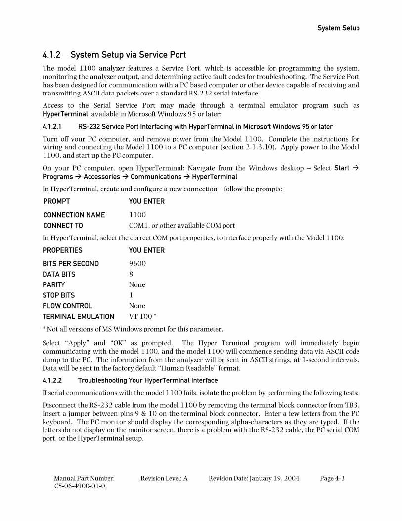
In HyperTerminal, create and configure a new connection – follow the prompts:
PROMPT YOU ENTER
CONNECTION NAME 1100
CONNECT TO COM1, or other available COM port
In HyperTerminal, select the correct COM port properties, to interface properly with the Model 1100:
PROPERTIES YOU ENTER
BITS PER SECOND 9600
DATA BITS 8
PARITY None
STOP BITS 1
FLOW CONTROL None
TERMINAL EMULATION VT 100 *
* Not all versions of MS Windows prompt for this parameter.
Select “Apply” and “OK” as prompted. The Hyper Terminal program will immediately begin communicating with the model 1100, and the model 1100 will commence sending data via ASCII code dump to the PC. The information from the analyzer will be sent in ASCII strings, at 1-second intervals. Data will be sent in the factory default “Human Readable” format.
4.1.2.2 Troubleshooting Your HyperTerminal Interface
If serial communications with the model 1100 fails, isolate the problem by performing the following tests:
Disconnect the RS-232 cable from the model 1100 by removing the terminal block connector from TB3. Insert a jumper between pins 9 & 10 on the terminal block connector. Enter a few letters from the PC keyboard. The PC monitor should display the corresponding alpha-characters as they are typed. If the letters do not display on the monitor screen, there is a problem with the RS-232 cable, the PC serial COM port, or the HyperTerminal setup.
Maintenance and Troubleshooting
Manual Part Number: C5-06-4900-01-0
Revision Level: A Revision Date: January 19, 2004 Page 4-4
If the typed letters DO show on the monitor screen and serial communications with the model 1100 still has not been established, then PC COM port pins 2 & 3 (1100 pins 9 & 10) may be reversed. Verify the cable wiring (section 2.1.3.10). If no transmitted data from the model 1100 is seen on the monitor screen, call the Neutronics Inc. Service Department for further assistance.
4.1.2.3 Organization of RS-232 Serial Data
There are three levels of access through the service port that can be used for interfacing with the model 1100:
Standard Access: ASCII dump to a PC, printer, or DAQ, and provides basic operator access.
Advanced Level-1 Access: Allows user setup and configuration, such as alarms, and data format.
Advanced Level-2 Access: Allows access to vital control areas via password.
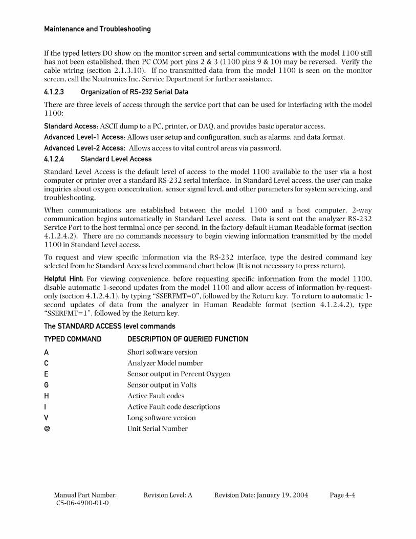
4.1.2.4 Standard Level Access
Standard Level Access is the default level of access to the model 1100 available to the user via a host computer or printer over a standard RS-232 serial interface. In Standard Level access, the user can make inquiries about oxygen concentration, sensor signal level, and other parameters for system servicing, and troubleshooting.
When communications are established between the model 1100 and a host computer, 2-way communication begins automatically in Standard Level access. Data is sent out the analyzer RS-232 Service Port to the host terminal once-per-second, in the factory-default Human Readable format (section 4.1.2.4.2). There are no commands necessary to begin viewing information transmitted by the model 1100 in Standard Level access.
To request and view specific information via the RS-232 interface, type the desired command key selected from he Standard Access level command chart below (It is not necessary to press return).
Helpful Hint: For viewing convenience, before requesting specific information from the model 1100, disable automatic 1-second updates from the model 1100 and allow access of information by-request-only (section 4.1.2.4.1), by typing “SSERFMT=0”, followed by the Return key. To return to automatic 1-second updates of data from the analyzer in Human Readable format (section 4.1.2.4.2), type “SSERFMT=1”, followed by the Return key.
The STANDARD ACCESS level commands
TYPED COMMAND DESCRIPTION OF QUERIED FUNCTION
A Short software version
C Analyzer Model number
E Sensor output in Percent Oxygen
G Sensor output in Volts
H Active Fault codes
I Active Fault code descriptions
V Long software version
@ Unit Serial Number
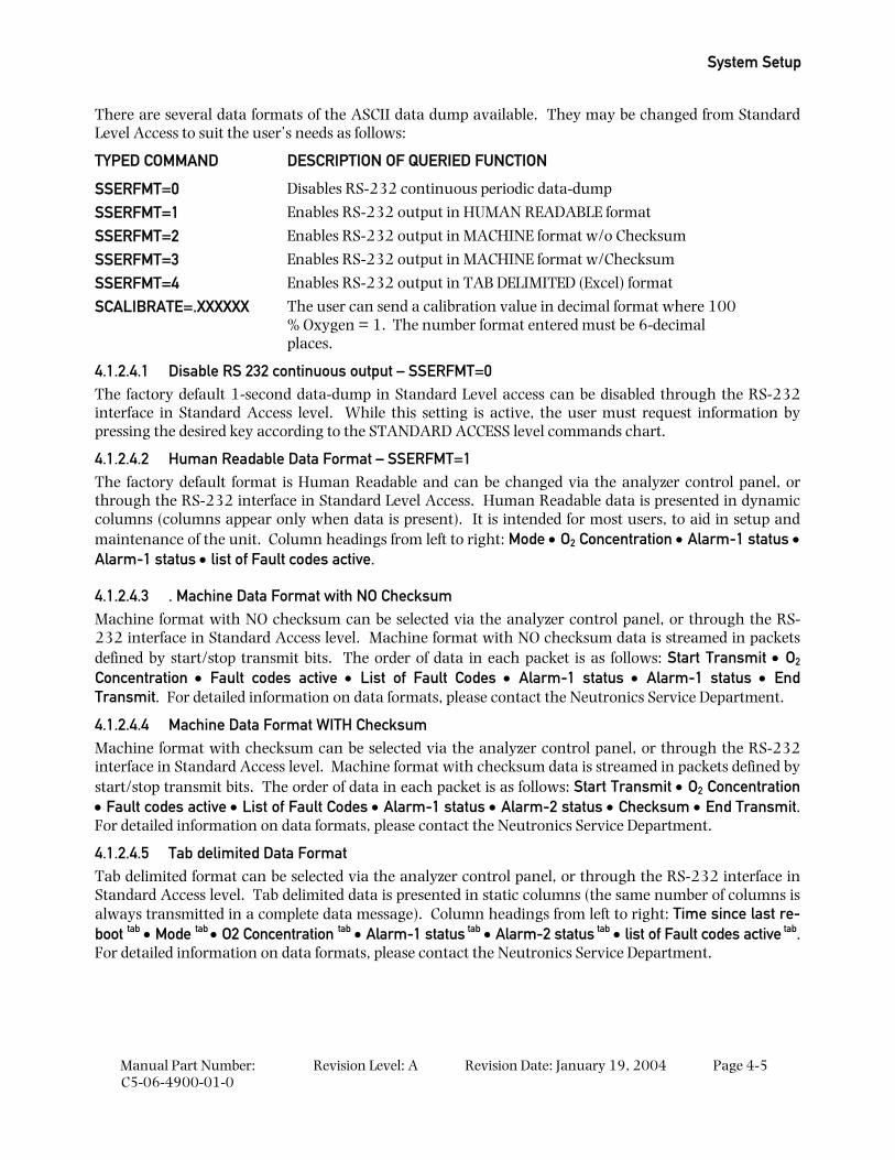
System Setup
Manual Part Number: C5-06-4900-01-0
Revision Level: A Revision Date: January 19, 2004 Page 4-5
There are several data formats of the ASCII data dump available. They may be changed from Standard Level Access to suit the user’s needs as follows:
TYPED COMMAND DESCRIPTION OF QUERIED FUNCTION
SSERFMT=0 Disables RS-232 continuous periodic data-dump
SSERFMT=1 Enables RS-232 output in HUMAN READABLE format
SSERFMT=2 Enables RS-232 output in MACHINE format w/o Checksum
SSERFMT=3 Enables RS-232 output in MACHINE format w/Checksum
SSERFMT=4 Enables RS-232 output in TAB DELIMITED (Excel) format
SCALIBRATE=.XXXXXX The user can send a calibration value in decimal format where 100 % Oxygen = 1. The number format entered must be 6-decimal places.
4.1.2.4.1 Disable RS 232 continuous output – SSERFMT=0 The factory default 1-second data-dump in Standard Level access can be disabled through the RS-232 interface in Standard Access level. While this setting is active, the user must request information by pressing the desired key according to the STANDARD ACCESS level commands chart.
4.1.2.4.2 Human Readable Data Format – SSERFMT=1 The factory default format is Human Readable and can be changed via the analyzer control panel, or through the RS-232 interface in Standard Level Access. Human Readable data is presented in dynamic columns (columns appear only when data is present). It is intended for most users, to aid in setup and maintenance of the unit. Column headings from left to right: Mode • O2 Concentration • Alarm-1 status • Alarm-1 status • list of Fault codes active.
4.1.2.4.3 . Machine Data Format with NO Checksum Machine format with NO checksum can be selected via the analyzer control panel, or through the RS-232 interface in Standard Access level. Machine format with NO checksum data is streamed in packets defined by start/stop transmit bits. The order of data in each packet is as follows: Start Transmit • O2 Concentration • Fault codes active • List of Fault Codes • Alarm-1 status • Alarm-1 status • End Transmit. For detailed information on data formats, please contact the Neutronics Service Department.
4.1.2.4.4 Machine Data Format WITH Checksum Machine format with checksum can be selected via the analyzer control panel, or through the RS-232 interface in Standard Access level. Machine format with checksum data is streamed in packets defined by start/stop transmit bits. The order of data in each packet is as follows: Start Transmit • O2 Concentration • Fault codes active • List of Fault Codes • Alarm-1 status • Alarm-2 status • Checksum • End Transmit. For detailed information on data formats, please contact the Neutronics Service Department.
4.1.2.4.5 Tab delimited Data Format Tab delimited format can be selected via the analyzer control panel, or through the RS-232 interface in Standard Access level. Tab delimited data is presented in static columns (the same number of columns is always transmitted in a complete data message). Column headings from left to right: Time since last re-boot tab • Mode tab • O2 Concentration tab • Alarm-1 status tab • Alarm-2 status tab • list of Fault codes active tab. For detailed information on data formats, please contact the Neutronics Service Department.
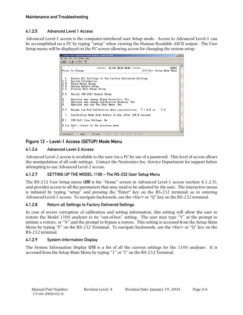
Maintenance and Troubleshooting
Manual Part Number: C5-06-4900-01-0
Revision Level: A Revision Date: January 19, 2004 Page 4-6
4.1.2.5 Advanced Level 1 Access
Advanced Level-1 access is the computer-interfaced user Setup mode. Access to Advanced Level-1 can be accomplished on a PC by typing “setup” when viewing the Human Readable ASCII output. The User Setup menu will be displayed on the PC screen allowing access for changing the system setup.
Figure 12 – Level-1 Access (SETUP) Mode Menu
4.1.2.6 Advanced Level-2 Access
Advanced Level-2 access is available to the user via a PC by use of a password. This level of access allows the manipulation of all code settings. Contact the Neutronics Inc. Service Department for support before attempting to use Advanced Level-2 access.
4.1.2.7 SETTING UP THE MODEL 1100 – The RS-232 User Setup Menu
The RS-232 User Setup menu U00 is the “Home” screen in Advanced Level-1 access (section 4.1.2.5), and provides access to all the parameters that may need to be adjusted by the user. The interactive menu is initiated by typing “setup” and pressing the "Enter" key on the RS-232 terminal; as in entering Advanced Level-1 access. To navigate backwards, use the <Esc> or “Q” key on the RS-232 terminal.
4.1.2.8 Return all Settings to Factory Delivered Settings
In case of severe corruption of calibration and setting information, this setting will allow the user to restore the Model 1100 analyzer to its “out-of-box” setting. The user may type “Y” at the prompt to initiate a restore, or “N” and the prompt to bypass a restore. This setting is accessed from the Setup Main Menu by typing “F” on the RS-232 Terminal. To navigate backwards, use the <Esc> or “Q” key on the RS-232 terminal.
4.1.2.9 System Information Display
The System Information Display U10 is a list of all the current settings for the 1100 analyzer. It is accessed from the Setup Main Menu by typing “1” or “I” on the RS-232 Terminal.
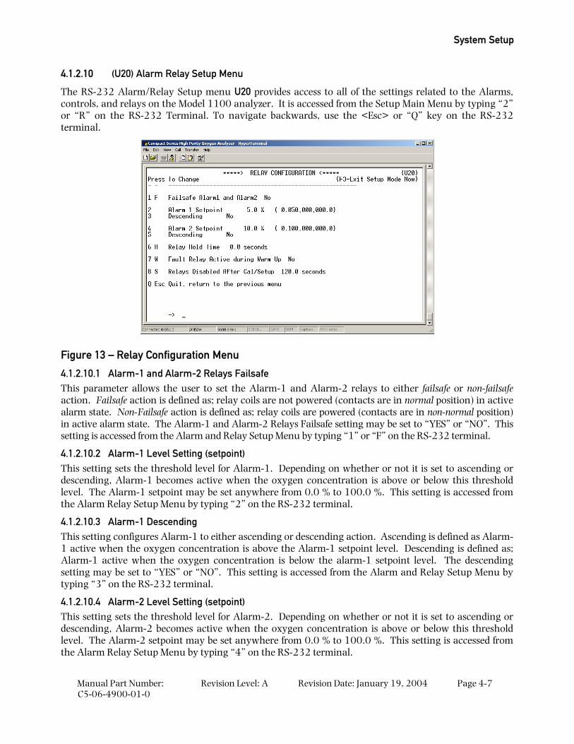
System Setup
Manual Part Number: C5-06-4900-01-0
Revision Level: A Revision Date: January 19, 2004 Page 4-7
4.1.2.10 (U20) Alarm Relay Setup Menu
The RS-232 Alarm/Relay Setup menu U20 provides access to all of the settings related to the Alarms, controls, and relays on the Model 1100 analyzer. It is accessed from the Setup Main Menu by typing “2” or “R” on the RS-232 Terminal. To navigate backwards, use the <Esc> or “Q” key on the RS-232 terminal.
Figure 13 – Relay Configuration Menu
4.1.2.10.1 Alarm-1 and Alarm-2 Relays Failsafe This parameter allows the user to set the Alarm-1 and Alarm-2 relays to either failsafe or non-failsafe action. Failsafe action is defined as; relay coils are not powered (contacts are in normal position) in active alarm state. Non-Failsafe action is defined as; relay coils are powered (contacts are in non-normal position) in active alarm state. The Alarm-1 and Alarm-2 Relays Failsafe setting may be set to “YES” or “NO”. This setting is accessed from the Alarm and Relay Setup Menu by typing “1” or “F” on the RS-232 terminal.
4.1.2.10.2 Alarm-1 Level Setting (setpoint) This setting sets the threshold level for Alarm-1. Depending on whether or not it is set to ascending or descending, Alarm-1 becomes active when the oxygen concentration is above or below this threshold level. The Alarm-1 setpoint may be set anywhere from 0.0 % to 100.0 %. This setting is accessed from the Alarm Relay Setup Menu by typing “2” on the RS-232 terminal.
4.1.2.10.3 Alarm-1 Descending This setting configures Alarm-1 to either ascending or descending action. Ascending is defined as Alarm-1 active when the oxygen concentration is above the Alarm-1 setpoint level. Descending is defined as; Alarm-1 active when the oxygen concentration is below the alarm-1 setpoint level. The descending setting may be set to “YES” or “NO”. This setting is accessed from the Alarm and Relay Setup Menu by typing “3” on the RS-232 terminal.
4.1.2.10.4 Alarm-2 Level Setting (setpoint) This setting sets the threshold level for Alarm-2. Depending on whether or not it is set to ascending or descending, Alarm-2 becomes active when the oxygen concentration is above or below this threshold level. The Alarm-2 setpoint may be set anywhere from 0.0 % to 100.0 %. This setting is accessed from the Alarm Relay Setup Menu by typing “4” on the RS-232 terminal.
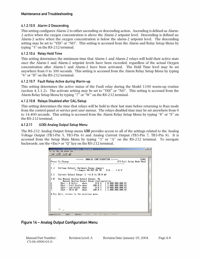
Maintenance and Troubleshooting
Manual Part Number: C5-06-4900-01-0
Revision Level: A Revision Date: January 19, 2004 Page 4-8
4.1.2.10.5 Alarm-2 Descending This setting configures Alarm-2 to either ascending or descending action. Ascending is defined as Alarm-2 active when the oxygen concentration is above the Alarm-2 setpoint level. Descending is defined as; Alarm-2 active when the oxygen concentration is below the alarm-2 setpoint level. The descending setting may be set to “YES” or “NO”. This setting is accessed from the Alarm and Relay Setup Menu by typing “5” on the RS-232 terminal.
4.1.2.10.6 Relay Hold Time This setting determines the minimum time that Alarm-1 and Alarm-2 relays will hold their active state once the Alarm-1 and Alarm-2 setpoint levels have been exceeded, regardless of the actual Oxygen concentration after Alarm-1 and Alarm-2 have been activated. The Hold Time level may be set anywhere from 0 to 300 seconds. This setting is accessed from the Alarm Relay Setup Menu by typing “6” or “H” on the RS-232 terminal.
4.1.2.10.7 Fault Relay Active during Warm-up This setting determines the active status of the Fault relay during the Model 1100 warm-up routine (section 4.3.1.2). The activate setting may be set to “YES” or “NO”. This setting is accessed from the Alarm Relay Setup Menu by typing “7” or “W” on the RS-232 terminal.
4.1.2.10.8 Relays Disabled after CAL/Setup This setting determines the time that relays will be held in their last state before returning to Run mode from the control panel or service port user menus. The relays disabled time may be set anywhere from 0 to 14,400 seconds. This setting is accessed from the Alarm Relay Setup Menu by typing “8” or “S” on the RS-232 terminal.
4.1.2.11 (U30) Analog Output Setup Menu
The RS-232 Analog Output Setup menu U30 provides access to all of the settings related to the Analog Voltage Output (TB3-Pin 5, TB3-Pin 6) and Analog Current Output (TB3-Pin 7, TB3-Pin 8). It is accessed from the Setup Main Menu by typing “3” or “A” on the RS-232 terminal. To navigate backwards, use the <Esc> or “Q” key on the RS-232 terminal.
Figure 14 – Analog Output Configuration Menu
System Setup
Manual Part Number: C5-06-4900-01-0
Revision Level: A Revision Date: January 19, 2004 Page 4-9
4.1.2.11.1 Analog Voltage Output Range This menu sets the Analog Voltage Output full-scale value. It may be set to 0 (0-5 VDC minimum to full scale), 1 (0-10 VDC minimum to full scale) or 2 (0-1 VDC minimum to full scale). This setting must match the RA and RB hardware jumper settings on the bottom of the main CPU PCB (section 4.1.3). This menu is accessed from the Analog Output Setup menu by typing “1” or “J” on the RS-232 terminal.
4.1.2.11.2 Analog Current Output Range This menu sets the Analog Current Output range. It may be set to 0 (0-20mA minimum to full scale), or 1 (4-20mA minimum to full scale). This menu is accessed from the Analog Output Setup menu by typing “2” or “I” on the RS-232 terminal.
4.1.2.11.3 Use Manual Analog Output Ranges This menu is used to enable manual override of Analog output mapping to display range, and to force minimum and maximum Analog outputs to absolute Oxygen measurement values. This menu is accessed from the Analog Output Setup menu by typing “3” or “M” on the RS-232 terminal.
4.1.2.11.4 Force minimum Voltage Output to O2 Concentration This menu sets the Oxygen concentration at which the Analog Voltage output is at zero. This setting is entered in percent oxygen increments, and can be anywhere from 0.0% to 100.0%. This menu is accessed from the Analog Output Setup menu by typing “4” on the RS-232 terminal.
4.1.2.11.5 Force Maximum Voltage to O2 Concentration This menu sets the Oxygen concentration at which the Analog Voltage output is at maximum range (section 4.1.2.11.1). This setting is entered in percent oxygen increments, and can be anywhere from 0.0 % to 100.0 %. This menu is accessed from the Analog Output Setup menu by typing “5” on the RS-232 terminal.
4.1.2.11.6 Force minimum Current Output to O2 Concentration This menu sets the Oxygen concentration at which the Analog Current output is at minimum range (section 4.1.2.11.2). This setting is entered in percent oxygen increments, and can be anywhere from 0.0 % to 100.0 %. This menu is accessed from the Analog Output Setup menu by typing “6” on the RS-232 terminal.
4.1.2.11.7 Force Maximum Current Output to O2 Concentration This menu sets the Oxygen concentration at which the Analog Current output is at maximum range (section 4.1.2.11.2). This setting is entered in percent oxygen increments, and can be anywhere from 0.0 % to 100.0 %. This menu is accessed from the Analog Output Setup menu by typing “7” on the RS-232 terminal.
4.1.2.12 (U14) Display/Auto-Range Setup
The RS-232 Display/Auto-Range Setup menu U14 provides access for the user to map the display and Analog output range scale(s) of the Model 1100 to suit the application (Appendix E – Range / Analog output Chart). The Analog Output Range may be set to 1 (fixed range 0-1 %) • 2 (fixed range 0-10 %) • 3 (fixed range 0-25 %) • 4 (fixed range 0-50 %) • 5 (fixed range 0-100 %) • 8 (low auto-range) • 9 (high auto-range) • 10 (full auto-range). This menu is accessed from the Setup Main Menu by typing “4” or “G” on the RS-232 terminal. To navigate backwards, use the <Esc> or “Q” key on the RS-232 terminal.
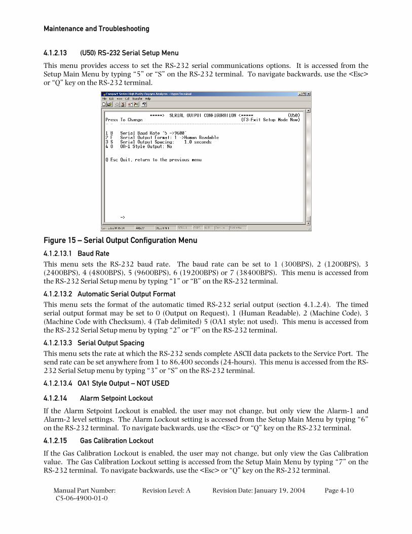
Maintenance and Troubleshooting
Manual Part Number: C5-06-4900-01-0
Revision Level: A Revision Date: January 19, 2004 Page 4-10
4.1.2.13 (U50) RS-232 Serial Setup Menu
This menu provides access to set the RS-232 serial communications options. It is accessed from the Setup Main Menu by typing “5” or “S” on the RS-232 terminal. To navigate backwards, use the <Esc> or “Q” key on the RS-232 terminal.
Figure 15 – Serial Output Configuration Menu
4.1.2.13.1 Baud Rate This menu sets the RS-232 baud rate. The baud rate can be set to 1 (300BPS), 2 (1200BPS), 3 (2400BPS), 4 (4800BPS), 5 (9600BPS), 6 (19200BPS) or 7 (38400BPS). This menu is accessed from the RS-232 Serial Setup menu by typing “1” or “B” on the RS-232 terminal.
4.1.2.13.2 Automatic Serial Output Format This menu sets the format of the automatic timed RS-232 serial output (section 4.1.2.4). The timed serial output format may be set to 0 (Output on Request), 1 (Human Readable), 2 (Machine Code), 3 (Machine Code with Checksum), 4 (Tab delimited) 5 (OA1 style; not used). This menu is accessed from the RS-232 Serial Setup menu by typing “2” or “F” on the RS-232 terminal.
4.1.2.13.3 Serial Output Spacing This menu sets the rate at which the RS-232 sends complete ASCII data packets to the Service Port. The send rate can be set anywhere from 1 to 86,400 seconds (24-hours). This menu is accessed from the RS-232 Serial Setup menu by typing “3” or “S” on the RS-232 terminal.
4.1.2.13.4 OA1 Style Output – NOT USED
4.1.2.14 Alarm Setpoint Lockout
If the Alarm Setpoint Lockout is enabled, the user may not change, but only view the Alarm-1 and Alarm-2 level settings. The Alarm Lockout setting is accessed from the Setup Main Menu by typing “6” on the RS-232 terminal. To navigate backwards, use the <Esc> or “Q” key on the RS-232 terminal.
4.1.2.15 Gas Calibration Lockout
If the Gas Calibration Lockout is enabled, the user may not change, but only view the Gas Calibration value. The Gas Calibration Lockout setting is accessed from the Setup Main Menu by typing “7” on the RS-232 terminal. To navigate backwards, use the <Esc> or “Q” key on the RS-232 terminal.
System Setup
Manual Part Number: C5-06-4900-01-0
Revision Level: A Revision Date: January 19, 2004 Page 4-11
4.1.2.15.1 User Menu Lockout If the Front Menu Lockout is enabled the user may not manually initiate any User mode from the control panel. The User Menu Lockout setting is accessed from the Control panel Locks menu by typing “8” on the RS-232 terminal. To navigate backwards, use the <Esc> or “Q” key on the RS-232 terminal.
4.1.2.16 Assume Low-End Calibration Range
WARNING: The Assume Low-End Calibration Range (Zero Calibration Range in the setup menu) is set to 0 % to 5 % Oxygen at the factory, and it should not be adjusted by the user. If the user changes the Assume Low-End Calibration Range setting, the model 1100 will not operate properly.
4.1.2.16.1 Calibration Mode Auto Return to RUN This setting determines the minimum time that the Model 1100 allows after exiting from control panel or service port user menus, before returning the unit to on-line status. The calibration mode auto return setting is accessed from the Control panel Locks menu by typing ”T” on the RS-232 terminal. To navigate backwards, use the <Esc> or “Q” key on the RS-232 terminal.
4.1.2.17 220 Volt Line Voltage – NOT USED
4.1.3 Change factory settings via Hardware Jumpers 4.1.3.1 Analog Voltage Output
The Analog voltage output must be configured using the hardware settings. In addition, the software settings must match the jumper settings. Software changes are made via the Control panel User Setup menu (section 4.1.1), or the Service Port RS-232 User Setup menu (section 4.1.2.7).
4.1.3.1.1 Remove the unit from service Make certain that all interfacing to the model 1100 is disabled at the user device. Make sure that interrupting outputs, from the unit will not interfere with normal process monitoring or control. Disconnect power from the model 1100 unit. Disconnect the removable terminal blocks from the rear of the model 1100 chassis. Follow all lock-out/tag-out procedures.
4.1.3.1.2 Change jumper settings Turn the model 1100 upside down to access the jumpers through the port provided. Identify the appropriate jumper position. Use an insulated jumper-puller to remove and replace jumpers (Figure 12).
4.1.3.1.3 Return to service Replace cables, and terminal blocks. Reapply power. Change Analog Voltage Output setting from control panel or service port to match new hardware settings. Perform a calibration check. Check function of changes to ensure the new settings are recognized by the model 1100.
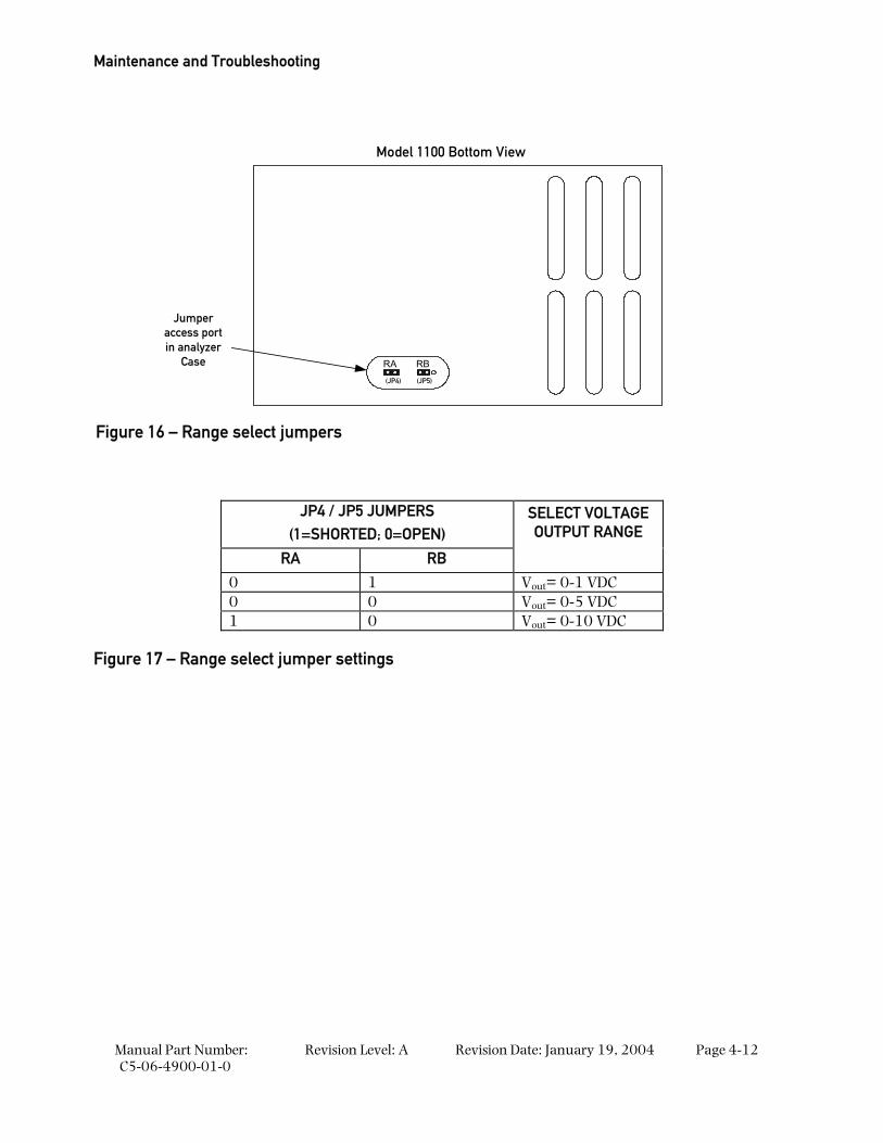
Maintenance and Troubleshooting
Manual Part Number: C5-06-4900-01-0
Revision Level: A Revision Date: January 19, 2004 Page 4-12
RA RB
(JP4) (JP5)
Jumperaccess portin analyzer
Case
Model 1100 Bottom View
JP4 / JP5 JUMPERS (1=SHORTED; 0=OPEN)
SELECT VOLTAGE OUTPUT RANGE
RA RB
0 1 Vout= 0-1 VDC 0 0 Vout= 0-5 VDC 1 0 Vout= 0-10 VDC
Figure 17 – Range select jumper settings
Figure 16 – Range select jumpers
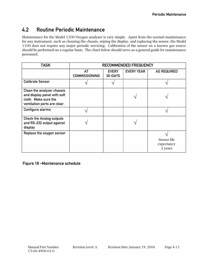
Periodic Maintenance
Manual Part Number: C5-06-4900-01-0
Revision Level: A Revision Date: January 19, 2004 Page 4-13
4.2 Routine Periodic Maintenance Maintenance for the Model 1100 Oxygen analyzer is very simple. Apart from the normal maintenance for any instrument, such as cleaning the chassis, wiping the display, and replacing the sensor, the Model 1100 does not require any major periodic servicing. Calibration of the sensor on a known gas source should be performed on a regular basis. The chart below should serve as a general guide for maintenance personnel.
TASK RECOMMENDED FREQUENCY AT
COMMISSIONING EVERY
30-DAYS EVERY YEAR AS REQUIRED
Calibrate Sensor √ √ √ Clean the analyzer chassis and display panel with soft cloth. Make sure the ventilation ports are clear.
√ √
Configure alarms √ √ Check the Analog outputs and RS-232 output against display
√ √
Replace the oxygen sensor
√
Sensor life expectancy
2 years
Figure 18 –Maintenance schedule
Maintenance and Troubleshooting
Manual Part Number: C5-06-4900-01-0
Revision Level: A Revision Date: January 19, 2004 Page 4-14
4.3 Troubleshooting
4.3.1 Fault Codes When trouble occurs during normal operation of the model 1100, the user has several tools available to aid in isolating the cause(s) of given symptoms. As a starting point, the user may use the control panel to enter into “View Active Faults” mode (section 3.2.4). The user may also view active faults and other useful information via the Service Port (section 4.1.2). In addition, there are four system Hot-Keys available to perform special functions, and to gather important information quickly and easily (Appendix-D). Descriptions of faults are given below, with indication of common causes. Refer to the appropriate sections of this manual for more details as needed.
4.3.1.1 Fault Code 2 – Relays are in Standby mode
The “Relays are in Standby mode” fault indicates that the user has aborted the control panel user mode menu properly (section 3.2.5), and the unit is in a stabilization period to allow time to sweep the sample lines with sample gas before returning the unit to on-line service. During the stabilization period, Alarm-1, Alarm-2, and Fault relays remain inactive, and held to their last state before the control panel user mode menu was accessed. The factory default setting for this period is 120-seconds. This setting is user-configurable (section 4.1.2.10.8).
4.3.1.2 Fault Code 3 – Device is in Setup mode – Service Port
The “Device is in Setup mode” fault indicates that the user has entered the user setup mode from the service port (section 4.1.2), and the model 1100 is not monitoring oxygen in the process. The 7-segment alphanumeric display will show “SU”. The Device is in Setup Mode fault will clear when the user returns the unit to Run mode.
4.3.1.3 Fault Code 5 – Analog Output range overflow
The “Analog Output range overflow” fault indicates an oxygen reading that is above the range configuration entered in the model 1100 setup (section 4.1.2.12). Possible causes of fault code-5 may be: Incorrect or contaminated calibration gases, faulty process or calibration sampling lines/components.
4.3.1.4 Fault Code 6 – Analog Output range underflow
The “Analog Output range overflow” fault indicates an oxygen reading that is below the range configuration entered in the model 1100 setup (section 4.1.2.12). Possible causes of fault code-6 may be: Analog Range lower limit set to a value greater than zero (section 4.1.2.11.1).
4.3.1.5 Fault Code 8 – A concentration reading is not yet available
The “concentration reading is not yet available” fault is active when the model 1100 is not ready for online service. It is active during start-up, calibration and during fault code-2 – relays are in standby mode.
4.3.1.6 Fault Code 10 –Sensor appears to be disconnected
The “Sensor appears to be disconnected” fault indicates that there is not a continuous electrical circuit connecting the Model 1100 and the oxygen sensor. Possible causes may be: An open in the sensor interface wiring, faulty connecting hardware on/in the model 1100 or the sensor, the sensor interface cable has been un-plugged.
Troubleshooting
Manual Part Number: C5-06-4900-01-0
Revision Level: A Revision Date: January 19, 2004 Page 4-15
4.3.1.7 Fault Code 11 – Non-native display range
The “non-native display range” fault indicates an oxygen reading that is above the range configuration entered in the model 1100 setup (section 4.1.2.12). Fault code-11 is active when fault code 5 is active. Possible causes of fault code-11 may be: Incorrect or contaminated calibration gases, faulty process or calibration sampling lines/components.
4.3.1.8 Fault Code 12 – User calibration too large
The “user calibration too large” fault indicates that the reading during calibration was out of tolerance high with respect to the known calibration gas concentration. The calibration tolerance window is factory-set and cannot be changed by the user. Possible causes of fault code-12 may be: Incorrect or contaminated calibration gases, faulty process or calibration sampling lines/components.
4.3.1.9 Fault Code 13 – User calibration too small
The “user calibration too small” fault indicates that the reading during calibration was out of tolerance low with respect to the known calibration gas concentration. The calibration tolerance window is factory-set and cannot be changed by the user. Possible causes of fault code-13 may be: Incorrect or contaminated calibration gases, faulty process or calibration sampling lines/components, faulty or failing sensor.
4.3.1.10 Fault Code 15 – Bad user calibration
The “bad user calibration” fault indicates that the user has attempted to calibrate the model 1100 with what appears to be a faulty sensor. Possible causes of fault code 15 are: Incorrect or contaminated calibration gases, improper calibration procedure, faulty sensor.

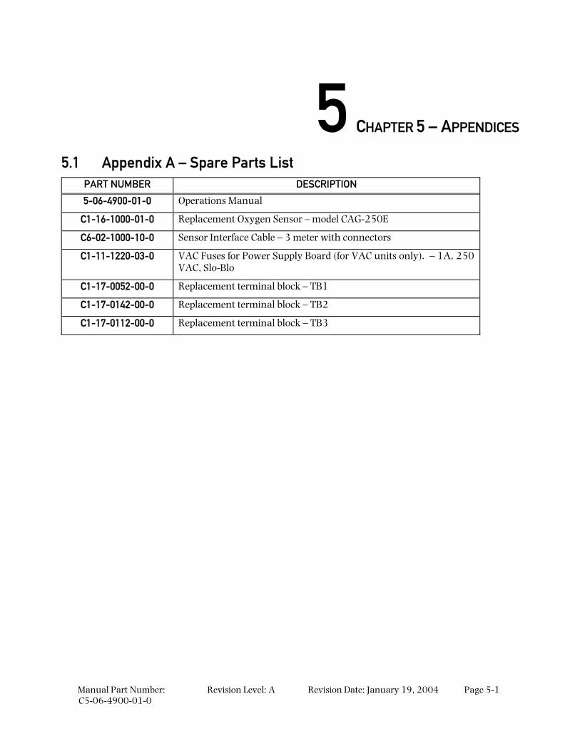
Manual Part Number: C5-06-4900-01-0
Revision Level: A Revision Date: January 19, 2004 Page 5-1
5 CHAPTER 5 – APPENDICES
5.1 Appendix A – Spare Parts List PART NUMBER DESCRIPTION
5-06-4900-01-0 Operations Manual
C1-16-1000-01-0 Replacement Oxygen Sensor – model CAG-250E
C6-02-1000-10-0 Sensor Interface Cable – 3 meter with connectors
C1-11-1220-03-0 VAC Fuses for Power Supply Board (for VAC units only). – 1A, 250 VAC, Slo-Blo
C1-17-0052-00-0 Replacement terminal block – TB1
C1-17-0142-00-0 Replacement terminal block – TB2
C1-17-0112-00-0 Replacement terminal block – TB3
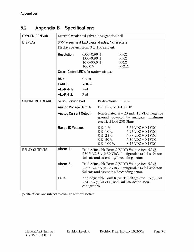
Appendices
Manual Part Number: C5-06-4900-01-0
Revision Level: A Revision Date: January 19, 2004 Page 5-2
5.2 Appendix B – Specifications
OXYGEN SENSOR External weak-acid galvanic oxygen fuel-cell
0.75” 7-segment LED digital display, 4 characters Displays oxygen from 0 to 100 percent.
Resolution: 0.00–0.99 % 1.00–9.99 % 10.0–99.9 % 100.0 %
X.XX X.XX XX.X XXX.X
Color -Coded LED’s for system status:
RUN: Green
FAULT: Yellow
ALARM-1: Red
DISPLAY
ALARM-2: Red
Serial Service Port: Bi-directional RS-232
Analog Voltage Output: 0–1, 0–5, or 0–10 VDC
Analog Current Output: Non-isolated 4 – 20 mA, 12 VDC, negative ground, powered by analyzer, maximum electrical load 250 Ohms
SIGNAL INTERFACE
Range ID Voltage: 0 %–1 % 0 %–10 % 0 %–25 % 0 %–50 % 0 %–100 %
5.63 VDC + 0.1VDC 6.25 VDC + 0.1VDC 6.88 VDC + 0.1VDC 7.50 VDC + 0.1VDC 8.13 VDC + 0.1VDC
Alarm-1: Field Adjustable Form C (SPDT) Voltage-free, 5A @ 250 VAC, 5A @ 30 VDC. Configurable to fail-safe/non fail-safe and ascending/descending action
Alarm-2: Field Adjustable Form C (SPDT) Voltage-free, 5A @ 250 VAC, 5A @ 30 VDC. Configurable to fail-safe/non fail-safe and ascending/descending action
RELAY OUTPUTS
Fault: Non-adjustable Form B (SPST) Voltage-free, 5A @ 250 VAC, 5A @ 30 VDC, non Fail Safe action, non-configurable.
Specifications are subject to change without notice.
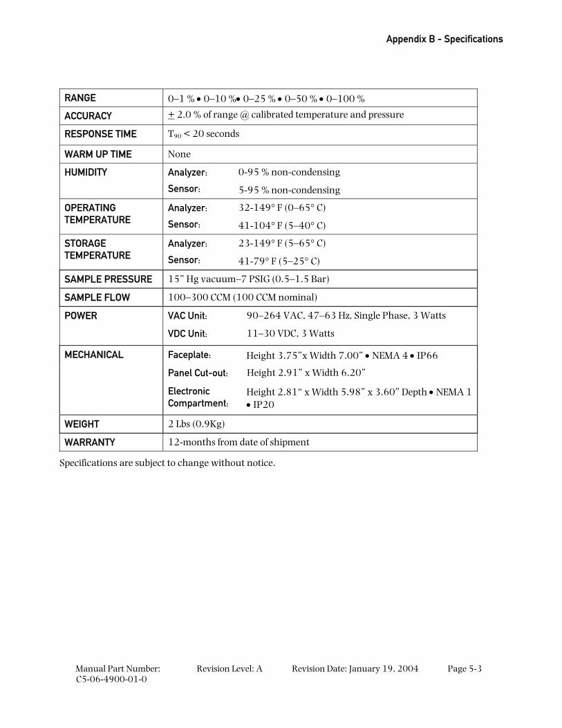
Appendix B - Specifications
Manual Part Number: C5-06-4900-01-0
Revision Level: A Revision Date: January 19, 2004 Page 5-3
RANGE 0–1 % • 0–10 %• 0–25 % • 0–50 % • 0–100 %
ACCURACY + 2.0 % of range @ calibrated temperature and pressure
RESPONSE TIME T90 < 20 seconds
WARM UP TIME None
Analyzer: 0-95 % non-condensing HUMIDITY
Sensor: 5-95 % non-condensing
Analyzer: 32-149° F (0–65° C) OPERATING TEMPERATURE Sensor: 41-104° F (5–40° C)
Analyzer: 23-149° F (5–65° C) STORAGE TEMPERATURE Sensor: 41-79° F (5–25° C)
SAMPLE PRESSURE 15” Hg vacuum–7 PSIG (0.5–1.5 Bar)
SAMPLE FLOW 100–300 CCM (100 CCM nominal)
VAC Unit: 90–264 VAC, 47–63 Hz, Single Phase, 3 Watts POWER
VDC Unit: 11–30 VDC, 3 Watts
Faceplate: Height 3.75”x Width 7.00” • NEMA 4 • IP66
Panel Cut-out: Height 2.91” x Width 6.20”
MECHANICAL
Electronic Compartment:
Height 2.81“ x Width 5.98” x 3.60” Depth • NEMA 1 • IP20
WEIGHT 2 Lbs (0.9Kg)
WARRANTY 12-months from date of shipment
Specifications are subject to change without notice.
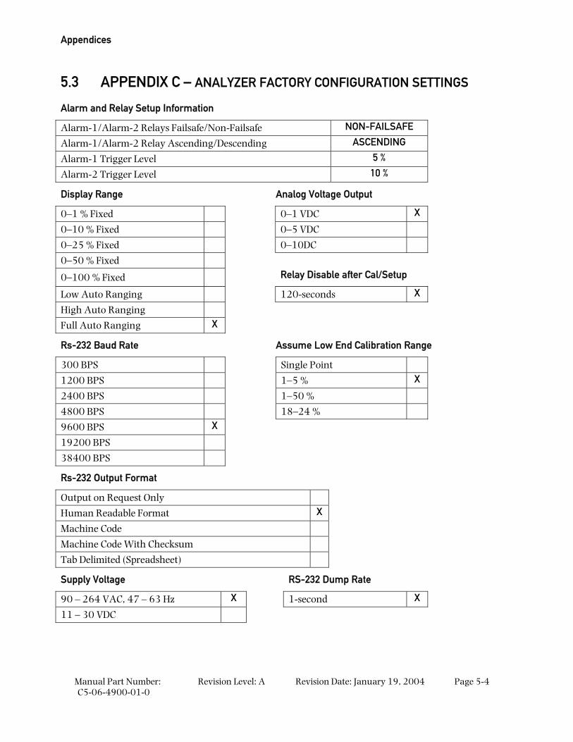
Appendices
Manual Part Number: C5-06-4900-01-0
Revision Level: A Revision Date: January 19, 2004 Page 5-4
5.3 APPENDIX C – ANALYZER FACTORY CONFIGURATION SETTINGS
Alarm and Relay Setup Information
Alarm-1/Alarm-2 Relays Failsafe/Non-Failsafe NON-FAILSAFE
Alarm-1/Alarm-2 Relay Ascending/Descending ASCENDING
Alarm-1 Trigger Level 5 %
Alarm-2 Trigger Level 10 %
Display Range Analog Voltage Output
0–1 % Fixed 0–1 VDC X
0–10 % Fixed 0–5 VDC
0–25 % Fixed 0–10DC
0–50 % Fixed
0–100 % Fixed Relay Disable after Cal/Setup
Low Auto Ranging 120-seconds X
High Auto Ranging
Full Auto Ranging X
Rs-232 Baud Rate Assume Low End Calibration Range
300 BPS Single Point
1200 BPS 1–5 % X
2400 BPS 1–50 %
4800 BPS 18–24 %
9600 BPS X
19200 BPS
38400 BPS
Rs-232 Output Format
Output on Request Only
Human Readable Format X
Machine Code
Machine Code With Checksum
Tab Delimited (Spreadsheet)
Supply Voltage RS-232 Dump Rate
90 – 264 VAC, 47 – 63 Hz X 1-second X
11 – 30 VDC
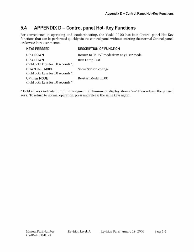
Appendix D – Control Panel Hot-Key Functions
Manual Part Number: C5-06-4900-01-0
Revision Level: A Revision Date: January 19, 2004 Page 5-5
5.4 APPENDIX D – Control panel Hot-Key Functions For convenience in operating and troubleshooting, the Model 1100 has four Control panel Hot-Key functions that can be performed quickly via the control panel without entering the normal Control panel, or Service Port user menus.
KEYS PRESSED DESCRIPTION OF FUNCTION
UP + DOWN Return to “RUN” mode from any User mode
UP + DOWN (hold both keys for 10 seconds *)
Run Lamp Test
DOWN then MODE (hold both keys for 10 seconds *)
Show Sensor Voltage
UP then MODE (hold both keys for 10 seconds *)
Re-start Model 1100
* Hold all keys indicated until the 7-segment alphanumeric display shows “---“ then release the pressed keys. To return to normal operation, press and release the same keys again.
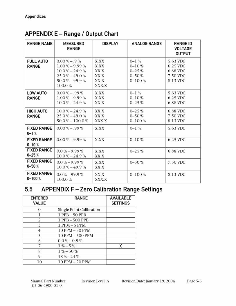
Appendices
Manual Part Number: C5-06-4900-01-0
Revision Level: A Revision Date: January 19, 2004 Page 5-6
APPENDIX E – Range / Output Chart
RANGE NAME MEASURED RANGE
DISPLAY ANALOG RANGE RANGE ID VOLTAGE OUTPUT
FULL AUTO RANGE
0.00 % – .9 % 1.00 % – 9.99 % 10.0 % – 24.9 % 25.0 % – 49.0 % 50.0 % – 99.9 % 100.0 %
X.XX X.XX XX.X XX.X XX.X XXX.X
0–1 % 0–10 % 0–25 % 0–50 % 0–100 %
5.63 VDC 6.25 VDC 6.88 VDC 7.50 VDC 8.13 VDC
LOW AUTO RANGE
0.00 % – .99 % 1.00 % – 9.99 % 10.0 % – 24.9 %
X.XX X.XX XX.X
0–1 % 0–10 % 0–25 %
5.63 VDC 6.25 VDC 6.88 VDC
HIGH AUTO RANGE
10.0 % – 24.9 % 25.0 % – 49.0 % 50.0 % – 100.0 %
XX.X XX.X XXX.X
0–25 % 0–50 % 0–100 %
6.88 VDC 7.50 VDC 8.13 VDC
FIXED RANGE 0–1 %
0.00 % – .99 % X.XX 0–1 % 5.63 VDC
FIXED RANGE 0–10 %
0.00 % – 9.99 % X.XX 0–10 % 6.25 VDC
FIXED RANGE 0–25 %
0.0 % – 9.99 % 10.0 % – 24.9 %
X.XX XX.X
0–25 % 6.88 VDC
FIXED RANGE 0–50 %
0.0 % – 9.99 % 10.0 % – 49.9 %
X.XX XX.X
0–50 % 7.50 VDC
FIXED RANGE 0–100 %
0.0 % – 99.9 % 100.0 %
XX.X XXX.X
0–100 % 8.13 VDC
5.5 APPENDIX F – Zero Calibration Range Settings ENTERED
VALUE RANGE AVAILABLE
SETTINGS
0 Single Point Calibration 1 1 PPB – 50 PPB 2 1 PPB – 500 PPB 3 1 PPM – 5 PPM 4 10 PPM – 50 PPM 5 10 PPM – 500 PPM 6 0.0 % – 0.5 % 7 1 % – 5 % X 8 1 % – 50 % 9 18 % - 24 %
10 10 PPM – 20 PPM
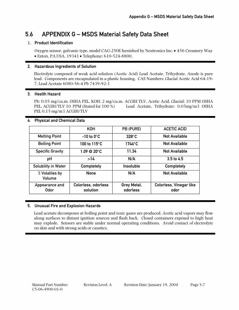
Appendix G – MSDS Material Safety Data Sheet
Manual Part Number: C5-06-4900-01-0
Revision Level: A Revision Date: January 19, 2004 Page 5-7
5.6 APPENDIX G – MSDS Material Safety Data Sheet 1. Product Identification
Oxygen sensor, galvanic type, model CAG-250E furnished by Neutronics Inc. • 456 Creamery Way • Exton, PA USA, 19341 • Telephone: 610-524-8800.
2. Hazardous Ingredients of Solution
Electrolyte composed of weak acid solution (Acetic Acid) Lead Acetate, Trihydrate. Anode is pure lead. Components are encapsulated in a plastic housing. CAS Numbers: Glacial Acetic Acid 64-19-7, Lead Acetate 6080-56-4 Pb 7439-92-1
3. Health Hazard
Pb: 0.05 mg/cu.m. OSHA PEL, KOH: 2 mg/cu.m. ACGIH TLV, Acetic Acid, Glacial: 10 PPM OSHA PEL, ACGIH/TLV 10 PPM (Stated for 100 %) Lead Acetate, Trihydrate: 0.05mg/m3 OSHA PEL 0.15 mg/m3 ACGIH/TLV
4. Physical and Chemical Data
KOH PB (PURE) ACETIC ACID
Melting Point -10 to 0°C 328°C Not Available
Boiling Point 100 to 115°C 1744°C Not Available
Specific Gravity 1.09 @ 20°C 11.34 Not Available
pH >14 N/A 3.5 to 4.5
Solubility in Water Completely Insoluble Completely
% Volatiles by Volume
None N/A Not Available
Appearance and Odor
Colorless, odorless solution
Grey Metal, odorless
Colorless, Vinegar like odor
5. Unusual Fire and Explosion Hazards
Lead acetate decomposes at boiling point and toxic gases are produced. Acetic acid vapors may flow along surfaces to distant ignition sources and flash back. Closed containers exposed to high heat may explode. Sensors are stable under normal operating conditions. Avoid contact of electrolyte on skin and with strong acids or caustics.
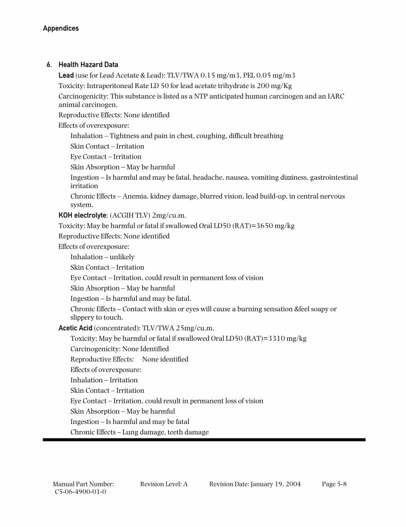
Appendices
Manual Part Number: C5-06-4900-01-0
Revision Level: A Revision Date: January 19, 2004 Page 5-8
6. Health Hazard Data Lead (use for Lead Acetate & Lead): TLV/TWA 0.15 mg/m3, PEL 0.05 mg/m3 Toxicity: Intraperitoneal Rate LD 50 for lead acetate trihydrate is 200 mg/Kg Carcinogenicity: This substance is listed as a NTP anticipated human carcinogen and an IARC animal carcinogen. Reproductive Effects: None identified Effects of overexposure:
Inhalation – Tightness and pain in chest, coughing, difficult breathing Skin Contact – Irritation Eye Contact – Irritation Skin Absorption – May be harmful Ingestion – Is harmful and may be fatal, headache, nausea, vomiting dizziness, gastrointestinal irritation Chronic Effects – Anemia, kidney damage, blurred vision, lead build-up, in central nervous system.
KOH electrolyte: (ACGIH TLV) 2mg/cu.m. Toxicity: May be harmful or fatal if swallowed Oral LD50 (RAT)=3650 mg/kg Reproductive Effects: None identified Effects of overexposure:
Inhalation – unlikely Skin Contact – Irritation Eye Contact – Irritation, could result in permanent loss of vision Skin Absorption – May be harmful Ingestion – Is harmful and may be fatal. Chronic Effects – Contact with skin or eyes will cause a burning sensation &feel soapy or slippery to touch.
Acetic Acid (concentrated): TLV/TWA 25mg/cu.m. Toxicity: May be harmful or fatal if swallowed Oral LD50 (RAT)=3310 mg/kg Carcinogenicity: None Identified Reproductive Effects: None identified Effects of overexposure: Inhalation – Irritation Skin Contact – Irritation Eye Contact – Irritation, could result in permanent loss of vision Skin Absorption – May be harmful Ingestion – Is harmful and may be fatal Chronic Effects – Lung damage, teeth damage
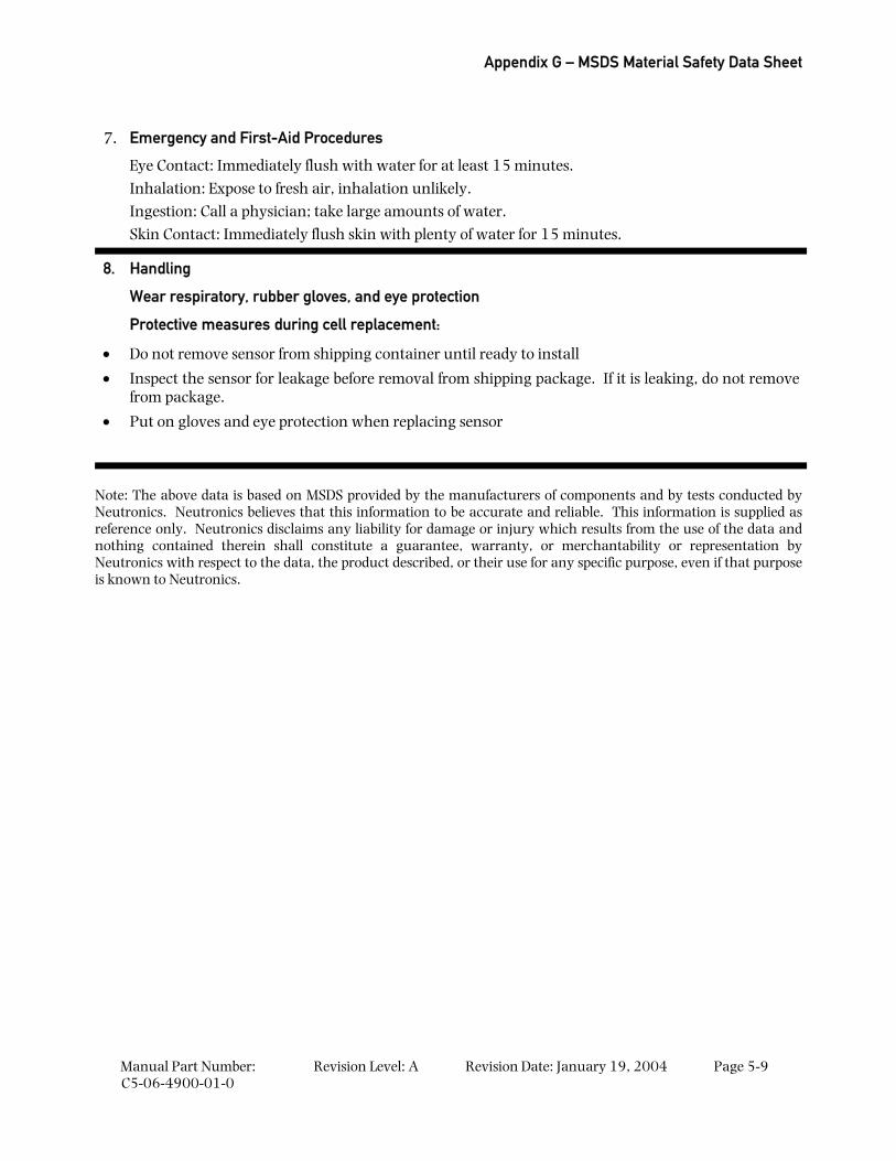
Appendix G – MSDS Material Safety Data Sheet
Manual Part Number: C5-06-4900-01-0
Revision Level: A Revision Date: January 19, 2004 Page 5-9
7. Emergency and First-Aid Procedures
Eye Contact: Immediately flush with water for at least 15 minutes. Inhalation: Expose to fresh air, inhalation unlikely. Ingestion: Call a physician; take large amounts of water. Skin Contact: Immediately flush skin with plenty of water for 15 minutes.
8. Handling
Wear respiratory, rubber gloves, and eye protection
Protective measures during cell replacement:
• Do not remove sensor from shipping container until ready to install
• Inspect the sensor for leakage before removal from shipping package. If it is leaking, do not remove from package.
• Put on gloves and eye protection when replacing sensor
Note: The above data is based on MSDS provided by the manufacturers of components and by tests conducted by Neutronics. Neutronics believes that this information to be accurate and reliable. This information is supplied as reference only. Neutronics disclaims any liability for damage or injury which results from the use of the data and nothing contained therein shall constitute a guarantee, warranty, or merchantability or representation by Neutronics with respect to the data, the product described, or their use for any specific purpose, even if that purpose is known to Neutronics.
Appendices
Manual Part Number: C5-06-4900-01-0
Revision Level: A Revision Date: January 19, 2004 Page 5-10
5.7 APPENDIX H – Warranty Neutronics warrants to the original purchaser, that the Model 1100 Oxygen analyzer is free from defects in material and workmanship for a period of one (1) year from the date of shipment from Neutronics or from one of Neutronics’ authorized dealers. Our liability will be limited to the repair or replacement, at our factory, of parts found to be defective within the warranty period, as determined by Neutronics. The parts will be repaired or replaced free of charge if shipped prepaid to the factory in the original shipping carton. This warranty is void if the product has been subject to misuse or abuse, including but not limited to: exposure to water, humidity, temperature, shock or pressure outside of the listed specifications, or has not been operated or installed in accordance with operating and maintenance instructions, for repairs which were not performed by Neutronics or by one of its authorized dealers, or if the identifying markings on the product label have been altered or removed.
The seller assumes no liability for consequential damages of any kind, and the buyer, by acceptance through purchase of this product, will assume all liability for the consequences of its use or misuse by the buyer, his employees, or others.
Neutronics reserves the right to use any materials in the manufacture, repair or service of the products and to modify the design as deemed suitable, in so far as these materials or modifications maintain the stated warranty.
It is the sole responsibility of the buyer / user to determine if this product is suitable for the intended application.
THESE WARRANTIES ARE EXCLUSIVE AND IN LIEU OF ALL OTHER WARRANTIES, EXPRESSED, OR IMPLIED INCLUDING WARRANTY OF MERCHANTABILITY, FITNESS FOR A PARTICULAR PURPOSE.
Intended Use for the Model 1100 The model 1100 Oxygen analyzer was designed to provide the trained operator with useful information relating to the concentration of Oxygen. This information may be used in process control or to minimize possible hazardous conditions, which may be present in various processes. Before implementation, the user must fully understand the operation and limitations of this instrument as well as the application for its use. The responsibility for the proper application, operation, installation, and maintenance of the model 1100 Oxygen analyzer is the sole obligation of the trained operator. The purchaser is required to ensure operators are properly trained in the use of this unit as well as in the possible hazards associated with its use or with the intended application. The purchaser must ensure that all of the proper warnings, labels, instruction manuals, lock outs, redundant components, hazard analysis, and system validation have been completed and provided to the trained operator before implementation of the model 1100 instrument.