Embed Size (px)
Citation preview
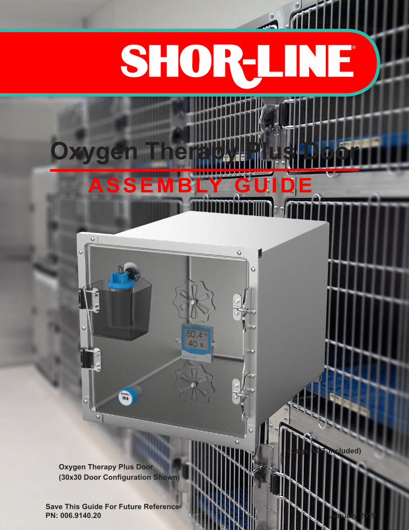
Save This Guide For Future Reference PN 006914020 January 2019
Oxygen Therapy Plus Door
ASSEMBLY GUIDE
Oxygen Therapy Plus Door
(30x30 Door Configuration Shown)
(Cage NOT Included)
Shor-Linecomii
INTRODUCTION
Introduction
Thank you for purchasing Shor-Line products As a leader in animal care equipment our
commitment to provide quality products and personable customer service is the same as it
was in 1927
This Guide provides information regarding the installation use and care of your Shor-Line
product Keep this Guide in a safe and convenient place for reference
For further questions to purchase additional products or to replace a lost or damaged
Guide please feel free to contact Shor-Line
SHOR-LINE
Schroer Manufacturing Company
511 Osage Ave
Kansas City Kansas 66105 USA
PHONE 8004441579
LOCAL 9132811500
FAX 9132815339
EMAIL guidesshor-linecom
WEB ADDRESS SHOR-LINEcom
SHOR-LINE LIMITED
Vale Business Park Llandow
Vale of Glamorgan CF71 7PF
United Kingdom
PHONE +44 1446 77 20 41
FAX +44 1446 77 36 68
EMAIL qualityshor-linecouk
WEB ADDRESS SHOR-LINEcouk
Shor-Line may provide instructions that supplement or supersede this Guide at any time
Contact Shor-Line to ensure the Guide is the latest version
During installation if a contradiction between this Guide existing conditions or local
regulations arise contact a Shor-Line representative before proceeding with installation
Visit Shor-linecom for a full list of TERMS AND CONDITIONS
copy Copyright 2019 Schroer Manufacturing Company All rights reserved
READ THIS GUIDE COMPLETELY BEFORE INSTALLATION AND USE AND
THOROUGHLY UNDERSTAND AND FOLLOW ALL SAFETY INSTRUCTIONS
WEAR PERSONAL PROTECTIVE EQUIPMENT such as but not limited to eye
protection back support brace and gloves during installation Failure to do so could
result in SERIOUS INJURY
This product is intended to be used for animals only Do not use for anything other than
the intended purpose
INTRODUCTION
iiiShor-Linecom
INTRODUCTION
Introduction ii
GENERAL INFORMATION
General information1Safety Alert Symbol 1
Personal Protective Equipment (PPE) 1
Safety Warnings Included In This Guide 2
SECTION ONE PRE-ASSEMBLY
Shipment Inventory And Inspection3Oxygen Therapy Plus Door - Single Door Configuration 3
Oxygen Therapy Plus Door - Double Door Conversion Kit 3
Shipment Inventory 3
Shipment Inspection 3
Damage Reporting 4
Oxygen Therapy Plus Door Sizes 4
Component Parts List 5
Hardware Parts List 6
SECTION TWO ASSEMBLY PROCEDURES
Assembly Procedures 7Oxygen Therapy Plus Door Configurations 7
Cage Door Removal - Single Door 7
Cage Door Removal - Double Door 8
Double Door Latch Bar Removal 8
Oxygen Therapy Plus Door Installation 10
Oxygen Therapy Plus Door Installation - Double Door 11
SECTION THREE USE AND CARE
Oxygen Therapy Plus Door Use And Care 13Safe Use Practices 13
Component Instructions 13
Humidifier 13
Oxygen Analyzer 14
ThermometerHygrometer 15
Adjustable Vents 15
Reversing Cage Door Swing 15
Cage Hardware 15
Door RotationComponent Relocation 17
Hinge Bushing Procedures 19
General Maintenance amp Care 20
Maintenance Recommendations 20
Care Recommendations 20
SECTION FOUR TERMS amp CONDITIONS
Terms And Conditions 21Damaged Freight Procedures 21
Limited Warranty 22
Contact Information 23
CONTENTS
Shor-Linecom1
GENERAL INFORMATION
General information
Refer to the Guide images and content to assist with the installation of the product
Throughout the Guide safety notices provide help for a successful installation
The Oxygen Therapy Plus Door is also referred to as the O2 Door in this document
SAFETY FIRSTShor-Line uses the following symbols and signal words to identify potential hazards or
unsafe practices
Safety Alert Symbol
Indicates a potential personal injury hazard exists It is important to heed any
safety warning information associated with this alert symbol
Signal Words for Hazard Alerting Safety Messages
Indicates a hazardous situation which if not avoided WILL result in serious injury
or death
Indicates a hazardous situation which if not avoided COULD result in serious injury
or death
Indicates a hazardous situation which if not avoided COULD result in minor or
moderate injury
Important Information Symbol
Indicates information considered important but not directly hazard related
Personal Protective Equipment (PPE)
PPE refers to protective clothing or other equipment designed to protect against injury It
is the responsibility of the clientinstaller to ensure all local and federal codes are adhered
to during the installation and assembly of this product Included is a list of PPE items
suggested but not limited to protective equipment to help complete the installation safely
bull Eye protection bull Gloves
bull Metatarsal foot protection bull Back Support Brace
Shor-Line makes no guarantee implied or otherwise that the information included in
this Guide will be complete or failsafe or that the information will prevent an injury from
occurring Standard measures described may not reflect the full extent of all steps that may need to be taken in any given emergency instance
California Proposition 65 Warning
This product can expose you to chemicals
including chromium which are known to the
state of California to cause cancer For more
information go to wwwP65Warningscagov
SAFETY
2Shor-Linecom
Safety Warnings Included In This Guide
READ THIS GUIDE COMPLETELY BEFORE INSTALLATION AND USE AND
THOROUGHLY UNDERSTAND AND FOLLOW ALL SAFETY INSTRUCTIONS
WEAR PERSONAL PROTECTIVE EQUIPMENT (PPE) such as but not limited to eye
protection protective gloves and Metatarsalfoot protection during installation Failure
to do so could result in SERIOUS INJURY
Enlist help and USE SAFE LIFTING PRACTICES during assembly installation and
moving equipment
Oxygen Therapy Plus Doors and Stainless Steel Cages have sharp edges stay clear
of and DO NOT TOUCH exposed edges which if not avoided could result in SERIOUS
INJURY OR DEATH
This product is intended to be used for animals only Do not use for anything other than
the intended purpose
Keep hands clear of possible pinch areas when assembling parts which if not avoided
could result in MINOR to MODERATE INJURY
Keep hands fingers and patients limbs clear of possible pinch areas when adjusting the vents which if not avoided could result in MINOR to MODERATE INJURY
SAFETY
Shor-Linecom3
SECTION ONE PRE-ASSEMBLY
Shipment Inventory And Inspection
Oxygen Therapy Plus Door - Single Door Configuration
FIGURE 11 - Typical Oxygen Therapy Plus Door - Single Door Configuration
HUMIDIFIER
CONTAINER
JAMB SEAL
HEAD SEAL
OXYGEN SENSOR
(SOLD SEPARATELY)
JAMB SEAL
HUMIDIFIER ADAPTER
WLOCK SCREW
ADJUSTABLE VENTS
HYGROMETER-
THERMOMETERDOOR PLUG
Oxygen Therapy Plus Door - Double Door Conversion Kit
The Double Door Conversion Kit is the sum of the parts required to convert a Single Therapy
Door cage to a Double Door Configuration
FIGURE 12 - Typical Oxygen Therapy Plus Door - Double Door Conversion Kit
JAMB SEAL
HEAD SEAL
ADJUSTABLE VENTS
LATCH BAR
WSEALS
CONVERSION
DOOR
Shipment Inventory
At arrival unpack and inspect the shipment to ensure it is complete and free of damages
that may have occurred during shipping Compare the packing list with the shipment to
ensure all partscomponents have been received in good condition See FIGURES 11-15
Avoid using razor blade or cutting devices product surfaces scratch easily
Shipment Inspection
While verifying the shipment contents take a moment to inspect each component for
damage This should be done before the shipment is signed received and accepted If
damaged components are apparent follow the claim procedures set forth by the carrier
SE
CT
ION
ONE
4Shor-Linecom
Damage Reporting
Follow the instructions within Shor-Linersquos Damage and Freight Procedures Contact
Shor-Line (8004441579) immediately to expedite the process
After fifteen (15) calendar days of receipt of merchandise policies become void
Oxygen Therapy Plus Door Sizes
Oxygen Therapy Plus Doors are available in many sizes and can be configured for single door (SD) or double door (DD) cage applications to best serve a variety of space conditions
and facility requirements Refer to FIGURE 13
FIGURE 13 - Oxygen Therapy Plus Door (30x30 SD amp 48x30 DD Shown)
HEAD SEAL
OXYGEN SENSOR
(SOLD SEPARATELY)
HEAD SEAL
JAMB SEAL
02 DOOR
WCOMPONENTS
HYGROMETER-
THERMOMETER
JAMB SEAL
DOOR PLUG
(STANDARD)
HUMIDIFIER
JAMB SEAL
DD CONVERSION
LATCH BAR
CONTAINER
NOTE STAINLESS STEEL
CAGES NOT INCLUDED
CONVERSION
DOOR
Part Description
Single Door Conversion Kit
914242420 DOOR24X24OXYGEN THERAPY PLUS
914243020 DOOR24X30OXYGEN THERAPY PLUS
914243620 DOOR24X36OXYGEN THERAPY PLUS
914303020 DOOR30X30OXYGEN THERAPY PLUS
914303620 DOOR30X36OXYGEN THERAPY PLUS
914362420 DOOR36X24OXYGEN THERAPY PLUS
914363020 DOOR36X30OXYGEN THERAPY PLUS
914363620 DOOR36X36OXYGEN THERAPY PLUS
Double Door Conversion Kit
914243021 DOOR24X30O2 CONVERSION
bull 301022009 bull DOOR24 X 30 GLASS CONVERSIONTYPE 4
bull 300238400 bull BRACKETDDTOPLH24 INO2 DOOR PLUS
bull 300238500 bull BRACKETDDTOPRH24 INO2 DOOR PLUS
bull 714000800 bull ASSY30 IN DD CHANNELO2 DOOR PLUS
bull 300230200 bull BRACKETSIDE30 INO2 DOOR PLUS
914243621 DOOR24X36O2 CONVERSION
bull 301022010 bull DOOR24 X 36 GLASS CONVERSIONTYPE 4
bull 300238400 bull BRACKETDDTOPLH24 INO2 DOOR PLUS
bull 300238500 bull BRACKETDDTOPRH24 INO2 DOOR PLUS
bull 714000900 bull ASSY36 IN DD CHANNELO2 DOOR PLUS
bull 300230200 bull BRACKETSIDE30 INO2 DOOR PLUS
SECTION ONE
Shor-Linecom5
SECTION ONE
Component Parts List
FIGURE 14 - Oxygen Therapy Plus Door (30x30 Shown)
01
05
02
14
03
06
10 07
04
08 11
09
16
17 19
2012
18
15 13
Item Part Description Qty
01 NOTE 1 DOORGLASS WITH VENTSTYPE 4 1
02 NOTE 1 BRACKETSIDEO2 DOOR PLUS (Jamb Seal) 2
03 NOTE 1 BRACKETTOPO2 DOOR PLUS (Head Seal) 1
04 bull 182000900 bull SEAL360X5D W-H2 38 EPDM Per Foot
05 025000400 HUMIDIFIER (3 ea initial shipment) Replacements Sold Separately 1
06 301020701 CONTAINER PLASTICO2 DOOR 1
07 bull 310020600 bull ALUMINUM BRACKET 1
08 bull 310118100 bull WASHERO2 DOORALUMINUM 1
09 bull 310020900 bull ADAPTERHUMIDIFIER 1
10 bull 061100801 bull 10-32X875 RD HD PHILLIPS SS 2
11 bull 063100000 bull 10-32 HX NUT NYLOCK SS 2
12 195137700 O2 ANALYZEROXYGEN THERAPY PLUS (SOLD SEPARATELY) 1
13 bull 300231500 bull HOLE PLUG MALEO2 DOOR 1
14 bull 300231400 bull HOLE PLUGFEMALEO2 DOOR 1
15 bull 062250703 bull 250-20 X 750 FLAT HD PHL SS 1
16 025000500 HYGROMETER-THERMOMETER-BIG DIGIT 1
17 bull 714000018 bull WELDMENTBRKTHYGRO-THERMO 1
18 bull 062060701 bull 6-32X750 RD HD PHL SS 2
19 bull 065060010 bull 6 SPLIT LOCK WASHER PLTD 2
20 bull 064060010 bull 6-32 ACORN NUT SAE HI-CROWN SS 2
21 300230900 bull COVER02 ANALYZERTP 4 DOOR 1
NOTE 1 - Sizes vary contact Shor-Line Technical Service Department to verify cage sizes (18004441579)
21
6Shor-Linecom
Hardware Parts List
FIGURE 15 - Oxygen Therapy Plus Door Hardware
01
10
11
06
07
14
15
12 0915 13
08
05
16
02
04 03
Item Part Description Qty
01 NOTE 1 DOORGLASS WITH VENTSTYPE 4 1
02 714000100 WELDMNTHINGE TYPE 4 2
03 bull 181006300 bull BUSHING HINGE MALE KENNEL TYPE 3 2
04 bull 181006301 bull BUSHING HINGE FEMALE KENNEL TYPE 3 2
05 714000100 DOOR HINGE POST 2
06 bull 062251005 bull 250-20 X 1000 TRUSS HD PHIL SS 4
07 bull 065250000 bull 250 FL WASH SAE SS 4
08 bull 064250002 bull 250-20 HX NUT NYLOCK SS 4
09 714000200 WLDMNTLATCH PINTYPE 4 DOOR 2
10 bull 062251005 bull 250-20 X 1000 TRUSS HD PHIL SS 4
11 bull 065250000 bull 250 FL WASH SAE SS 4
12 bull 064250002 bull 250-20 HX NUT NYLOCK SS 4
13 301022011 DOORVENT COVERTYPE 4 2
14 bull 062251005 bull 250-20 X 1000 TRUSS HD PHIL SS 2
15 bull 065250000 bull 250 FL WASH SAE SS 4
16 bull 064250002 bull 250-20 HX NUT NYLOCK SS 2
NOTE 1 - Sizes vary contact Shor-Line Technical Service Department to verify cage sizes (18004441579)
SECTION ONE
Shor-Linecom7
SECTION TWO ASSEMBLY PROCEDURES
Assembly Procedures
Oxygen Therapy Plus Door ConfigurationsOxygen Therapy Plus Door (O2 Door) is available in several sizes The doors are designed
to be installed onto existing (sold separately) stainless steel cages Verify the width and
height of the cage with the dimensions of the O2 Door to be installed
The O2 Door is equipped with Type III hinges but with a hinge conversion kit the Type III O2 Door can be used with some older model Type II hinge cages Contact Shor-Line Technical
Service department to verify cage door types and compatibility (18004441579)
A second door equipped with vents only is used in combination with an O2 Door when
converting a 48 wide cage to a double door oxygen therapy cage Double door cages
share a latch bar centered between the doors The door hardware and components can be
reoriented to either locate the O2 Door on the left or right side of the cageDo NOT use power tools for any procedures listed in this manual Doing so can scratch
product surfaces andor cause hardware to fail Do NOT over-tighten hardware
Cage Door Removal - Single Door
Door hinges may vary depending on the cage model used for the Oxygen Therapy Plus
Door configuration Type III cages are used for these procedures Contact Shor-Line for door removal procedures and hardware requirements for older model cages
If equipped lock all casters on mobile cage banks to prevent movement during the
installation procedures
Enlist help and USE SAFE LIFTING PRACTICES during assembly installation and
moving equipment
Keep hands clear of possible pinch areas when assembling parts which if not avoided
could result in MINOR to MODERATE INJURY
STEP 1 Slide the latch bar up and swing the door to the open position (90deg to cage face)
See FIGURE 21
STEP 2 Lift the door upward sliding the bushings out of the hinge assemblies Set away
from the assembly area See FIGURE 22
FIGURE 21 - Open Door 90deg
UP TO RELEASE LATCH
SWING DOOR
90 DEGREES
FIGURE 22 - Door Removal
SLIDE DOOR UP
OUT OF HINGES
STEP 3 Clean and store unused grill doors and hardware for future re-installation
if needed
SE
CT
ION
TWO
8Shor-Linecom
Cage Door Removal - Double Door
Door hinges may vary depending on the release model of the cages Type III cages
are used for this procedure Contact Shor-Line for door removal procedures for older
model cages
STEP 1 Slide the latch bar up and swing the door to the open position (90deg to cage face)
See FIGURE 23
STEP 2 Lift the door up sliding the bushings out of the hinge assembly Set away from the
assembly area See FIGURE 24
FIGURE 23 - Open Door
UP TO RELEASE LATCH
SWING DOOR
90 DEGREES
FIGURE 24 - Door Removal
SLIDE DOOR UP
OUT OF HINGES
Enlist help and USE SAFE LIFTING PRACTICES during assembly installation and
moving equipment
Keep hands clear of possible pinch areas when assembling parts which if not avoided
could result in MINOR to MODERATE INJURY
STEP 3 Repeat Steps 1 and 2 to remove the second door
STEP 4 Clean and store unused grill doors and hardware for future re-installation
if needed
Double Door Latch Bar Removal
Shor-Lines double door cage share a latch bar that can
be easily removed for greater access when transferring
a patient into or out of the cage comfortably
The latch bar is also used for the divider panel The
larger double door cages can be split into two cages
by inserting the divider panel Divider panels are sold
separately contact Shor-Line for size availability
To convert a double door cage to an Oxygen Therapy
cage the latch bar must be replaced with the latch bar
which include jamb seal strips
The O2 Door latch bar is NOT equipped with a center divider slot Center dividers do not
seal the cage space Store center dividers with the removed grill doors and center latch
bar assembly for future use
FIGURE 25 - Center Latch wDivider
SECTION TWO
Shor-Linecom9
SECTION TWO
STEP 1 Open or remove both doors if not already done so
The latch bar has keyed (hole with a smaller slot) top holes And the bottom of the
latch bar uses open end slots enabling the bar to be slid out from behind the latch bar
retaining pins See FIGURE 26
FIGURE 26 - Standard Double Door Latch Bar
CENTER LATCH BAR
KEYHOLE SLOT
OPEN END
SLOT
STEP 2 Lift the latch bar upward to clear the keyhole slots located at the top of the latch
bar See FIGURE 27
FIGURE 27 - Latch Top Keyhole Slot
SLIDE UP
FIGURE 28 - Remove Latch Top
REMOVE FROM
LATCH PINS
STEP 3 Once clear of the keyhole slot pull the top of the latch bar clear of the latch upper
pins See FIGURE 28
STEP 4 Lift the latch bar upward to clear the
latch pins located at the bottom The
bottom of the latch bar has open end
slots at the end of the bar to easily slide
out from behind the latch lower pins
See FIGURE 29
FIGURE 29 - Remove Latch Bottom
SLIDE OUT
10Shor-Linecom
Oxygen Therapy Plus Door Installation
The O2 Door and components are packaged in
separate boxes Unpack and organize the door
components for assembly and installation
Enlist help and USE SAFE LIFTING
PRACTICES during assembly installation and
moving equipment
Keep hands clear of possible pinch areas when
assembling parts which if not avoided could
result in MINOR to MODERATE INJURY
STEP 1 Loosen trim plates hinges latch bar and trim strips Do NOT remove screws or
hardware See FIGURE 210
STEP 2 Align the slots on the jamb seal (side) with the hardware screws Slide the jamb
seal under the trim plates strips and hardware Secure the jamb seal with the
center screw do NOT fully tighten See FIGURE 211
STEP 3 Repeat STEP 2 for opposite side jamb seal
STEP 4 Align the slots on the head seal (top) with the hardware screws Slide the head
seal under the trim plates Secure the head seal by tightening the top trim plate
screws See FIGURE 212
FIGURE 211 - Jamb Seal Installation FIGURE 212 - Head Seal Installation
STEP 5 Tighten all trim plates strips and hardware to secure the jamb and head seals
in place
STEP 6 Install the O2 Door by holding the door hinge pinsbushings above the cage
hinges at a 90deg angle to the face of the cage Slide the hinge pinsbushings down
into the hinges See FIGURE 213
The hinge bushings have a flat side that slide through the opening in the hinge assembly The
flat side of the bushings must be facing away from the cage to align with the hinges The
hinge bushing must fully seat into the hinge for
proper operation
STEP 7 Close the door check latch operation and
adjust alignment to ensure the O2 Door
latches correctly
FIGURE 210 - Loosen Trim
LOOSEN DO NOT REMOVE
FIGURE 213 - Door Installation
PERPENDICULAR TO CAGE FACE
SECTION TWO
Shor-Linecom11
SECTION TWO
Oxygen Therapy Plus Door Installation - Double Door
The O2 Door and components are packaged in separate boxes Unpack and organize the door
components for assembly and installation
If equipped lock all casters on mobile cage banks to
prevent movement during the installation procedures
Enlist help and USE SAFE LIFTING
PRACTICES during assembly installation and
moving equipment
Keep hands clear of possible pinch areas when
assembling parts which if not avoided could
result in MINOR to MODERATE INJURY
STEP 1 Loosen trim plates hinges and trim strips Do NOT remove screws or hardware
See FIGURE 214
STEP 2 Align the slots on the jamb seal (side) with the hardware screws Slide the jamb
seal under the trim plates strips and hardware Secure the jamb seal with the
center screw do NOT fully tighten See FIGURE 215
STEP 3 Repeat STEP 2 for the opposite side jamb seal See FIGURE 216
FIGURE 215 - Left Jamb Seal Installation FIGURE 216 - Right Jamb Seal Installation
STEP 4 Align the slots on the head seal (top) with the hardware screws Slide the head
seal under the trim plates Secure the head seal by tightening the top trim plate
screws Do NOT fully tighten See FIGURE 217
STEP 5 Tighten all trim plates strips and hardware to secure the jamb and head seals
in place See FIGURE 218
FIGURE 217 - Left Head Seal Installation FIGURE 218 - Right Head Seal Installation
FIGURE 214 - Loosen Hardware
LOOSEN DO NOT FULLY
REMOVE SCREWSTRIM
12Shor-Linecom
STEP 6 The double door conversion kit includes a
latch bar equipped with jamb seals Follow
the latch bar removal procedures (reverse
order) to install the new latch bar assembly
See FIGURE 219
Ensure the slots in the end of the latch bar are
located on the bottom of the cage
STEP 7 Install the O2 Door by holding the door hinge
pinsbushings above the cage hinges at a
90deg angle to the face of the cage Slide the
hinge pinsbushings down into the hinges
See FIGURE 220
The hinge bushings have a flat side that slide through the opening in the hinge assembly The flat side of the bushings must be facing away from the cage to align with the hinges The hinge bushing must fully seat into the hinge for proper operation
STEP 8 Repeat STEP 7 to install the conversion door on the right-hand side of the cage
See FIGURE 221
FIGURE 220 - Door Installation FIGURE 221 - Door Installation
STEP 9 Close the doors check latch operation and adjust alignment to ensure the O2 Doors latch correctly
FIGURE 222 - 48 Wide Oxygen Therapy Plus Configuration (Options Vary)
FIGURE 219 - Latch Bar Installation
SECTION TWO
Shor-Linecom13
SECTION THREE USE AND CARE
Oxygen Therapy Plus Door Use And Care
Safe Use Practices
Always use safe practices during loading and unloading patients from cages All procedures
for cage use should be created by the facility owner and followed by all users Common
sense and being aware of safety concerns should always drive procedures Below is a list of
recommendations and situational conditions that require attention heed all warnings
bull Do NOT move a cage while occupied with animals
bull Do NOT force the cage door closed Verify alignment issues and correct as required
bull Do NOT move cages with the doors in the open position
Component Instructions
Oxygen Therapy Plus Door configurations vary and may or may not include all accessories Verify which components match the order and proceed to the componentsaccessories
sections required to complete the installation
Do NOT use powered tools for any procedures listed in this manual Doing so can
scratch product surfaces andor cause hardware to fail
FIGURE 31 - Oxygen Therapy Plus Door (30x30 SD amp 48x30 DD Shown)
SINGLE DOOR
CONFIGURATION
DOUBLE DOOR
CONFIGURATIONNOTE STAINLESS STEEL
CAGES NOT INCLUDED
OXYGEN SENSOR
(SOLD SEPARATELY)OXYGEN SENSOR
(SOLD SEPARATELY)
Enlist help and USE SAFE LIFTING PRACTICES during assembly installation and
moving equipment
Keep hands clear of possible pinch areas when assembling parts which if not avoided
could result in MINOR to MODERATE INJURY
Keep hands fingers and patients limbs clear of possible pinch areas when adjusting the vents which if not avoided could result in MINOR to MODERATE INJURY
HumidifierThe humidifier is designed to distribute humidified oxygen to the therapy cage A container is provided which holds either cold (ice) or warm water to control the temperature of the
humidified oxygen entering the cageSource oxygen is NOT provided The source oxygen line connects to the humidifier using a 916-18 male fitting supplying oxygen to the humidifier To bypass the humidifier attach a connector to the source oxygen line that can be secured into the adapter
THREESE
CT
ION
14Shor-Linecom
The humidifier container though disposable can be cleaned and reused several times Three are included with the initial shipment of the O2 Door
FIGURE 32 - Humidifier
ALUMINUM
BRACKET
HUMIDIFIER
CONTAINER
FIGURE 33 - Oxygen Analyzer
ALUMINUM
BRACKET
HUMIDIFIER
ADAPTER
HUMIDIFIER
HUMIDIFIER
CONTAINER
STEP 1 Install the humidifier container using the keyhole slots and exposed screw heads See FIGURE 32
STEP 2 Insert the humidifier into the humidifier adapter and secure with the retaining screw Slide the humidifieradapter into the aluminum bracket Add ice or water as required to adjust the temperature of the humidifier water See FIGURE 33
Refer to the manufacturers operation Safety warnings and maintenance procedures
Oxygen Analyzer
The oxygen analyzer is an optional component for the O2 Door sold separately The
oxygen analyzer can be used to spot check oxygen concentration within the O2 therapy
treatment cage
Refer to the manufacturers operation calibration and maintenance procedures
for instruction
STEP 1 Install the O2 Analyzer by removing the plug assembly with a Phillips head
screwdriver Clean and store the plug for replacement into the door when the
analyzer is not used See FIGURE 34
STEP 2 Insert the analyzer through the hole and secure with the cover thread onto the
analyzer hand tighten See FIGURE 35
FIGURE 34 - O2 Analyzer Plug Removal
REMOVE
PLUG
ASSEMBLY
FIGURE 35 - O2 Analyzer Installation
O2 ANALYZER
COVERO2 ANALYZER
Remove the O2 Analyzer before cleaning the door Avoid using cleaning chemicals
around the exposed end of the O2 Analyzer
Refer to the manufacturers operation safety warnings and maintenance procedures
SECTION THREE
Shor-Linecom15
SECTION THREE
ThermometerHygrometer
The O2 Door is equipped with a thermometerhygrometer which displays the temperature
and humidity level within the cage Refer to the manufacturers operation and
maintenance procedures
The Thermometer is attached to the inside of the cage door by a bracket Remove the meter
before cleaning the cage door replacing the battery and to access the FahrenheitCelsius
switch located on the back
STEP 1 Remove the two screws and acorn nuts to remove the bracket and meter See
FIGURE 36
STEP 2 Reinstall the meter using the two screws and acorn nuts to secure the bracket
and meter ensure the meter display orientation is correct See FIGURE 37
FIGURE 36 - Thermometer (Front View) FIGURE 37 - Thermometer (Back View)Always remove the meter and bracket before cleaning the cage door avoid using
chemicals around meter
Adjustable Vents
Vents located on the face of the cage door can be
rotated to increase or decrease the openings adjusting
the airflow into and out of the cage A patient occupied cage a heating pad humidified oxygen and ambient room conditions are all variables
that can effect the temperature and humidity levels inside the cage Adjust the vents as required to reduce
condensation within the cage
Keep hands fingers and patients limbs clear of possible pinch areas when adjusting the vents
which if not avoided could result in MINOR to
MODERATE INJURY
Reversing Cage Door Swing
The standard door swing is a right-hand pull with hinges located on the left and a latch on
the right Cage doors can be flipped to swing with a left-hand pull by relocating the hinges latch assembly and rotating the door (Single door cages only)
Cage Hardware
STEP 1 Remove the cage door by following the Type III hinge cage door
removal procedure
FIGURE 38 - Adjustable Vents
ROTATE
VENTS
16Shor-Linecom
SECTION THREE
STEP 2 Remove the hinge assemblies from the left side of the cage frame by removing
the screws See FIGURE 39
STEP 3 Remove the latch assembly from the right side of the cage fame by removing the
screws See FIGURE 310
FIGURE 39 - Hinge Assembly Removal
REMOVE
HINGES
FIGURE 310 - Latch Assembly Removal
REMOVE
LATCH
STEP 4 Flip rotate the latch assembly so the latch bar is on the inside of the cage frame
and that both latch guides are in the top position See FIGURE 311
The latch is designed for left or right operation Hold the latch guides while sliding the
latch bar down to the lowest position on both guides
STEP 5 Install the latch assembly to the cage frame tighten screws to secure the latch to
the frame See FIGURE 312
FIGURE 311 - Latch Assembly Rotate
RIGHT
SIDE
LATCH
LEFT
SIDE
LATCH
SLIDE
GUIDE
UP
SLIDE
GUIDE
UP
ROTATE
LATCH
180deg
FIGURE 312 - Latch Assembly Installation
TOP TWO
HOLES
BOTTOM
TWO HOLES
LATCH
SCREWS
STEP 6 Flip rotate the hinge assembly to the right side of the cage frame so that the
hinge bushing guide is located on the inside of the cage frame See FIGURE 313
STEP 7 Install the hinge assemblies to the cage frame tighten screws to secure the
hinges to the frame See FIGURE 314
FIGURE 313 - Hinge Assembly Rotate
HINGE
GUIDE
SLOT
HINGE
GUIDE
SLOT
INSIDE
OF CAGE
OUTSIDE
OF CAGE
FIGURE 314- Hinge Assembly Installation
HINGE
SCREWS
Shor-Linecom17
Door RotationComponent Relocation
The O2 Door can be flipped or rotated so that the door will swing in the opposite direction The componentsaccessories have to be removed relocated and reattached
Depending upon the configuration of the O2 Door components and procedures may vary
FIGURE 315 - Rotate Door
RIGHT-HAND
LATCH (PULL)
LEFT-HAND
LATCH (PULL)
ROTATE
DOOR
180deg
FIGURE 316 - Rotated Door
REMOVE
RELOCATE
REATTACH
HINGE
BUSHING
REMOVE
ROTATE
REATTACH
LATCH
POST
REMOVE
ROTATE
REATTACH
STEP 1 Rotate the door 180deg about the face so that the hinge bushings are located on the
right hand side of the door See FIGURE 315 amp 316
Remove rotate and reattach the Thermometer
Hygrometer to reorient the meter to read correctly
Ensure the meter is reinstalled on the backside (cage-
side) of the door
Do NOT attempt to remove the meter by sliding it
out of the bracket while still attached to the door
may scratch the door surface
STEP 2 Remove the two screws washers and
acorn nuts to detach the bracket and meter
Reinstall the meter to read upright See
FIGURE 317
The O2 door Humidifier holder and O2 analyzerdoor plug swap positions
STEP 3 Remove the O2 analyzerdoor plug
A O2 analyzer - Remove the O2 Analyzer by turning the cover (backside)
counterclockwise slide the O2 Analyzer out of the hole Set aside for the moment
See FIGURE 318
B Door Plug - Remove the door plug assembly with a Phillips head screwdriver turn
the screw counterclockwise to loosen remove Set aside for the moment See
FIGURE 319
FIGURE 318 - O2 Analyzer Removal
O2 ANALYZER
FIGURE 319 - Door Plug Removal
REMOVE
PLUG
ASSEMBLY
O2 ANALYZER
COVER
FIGURE 317 - ThermometerHygrometer
SECTION THREE
18Shor-Linecom
STEP 4 Using a Phillips head screwdriver and a wrench remove the humidifier holder See FIGURE 320
STEP 5 Rotate the humidifier holder orientating the bracket to align with the top hole in the door (lower two screw holes) Install the humidifier holder by reattaching the large washer on the backside of the door secure with the screws and nuts See
FIGURE 321
FIGURE 320 - Holder Removal
REMOVE
ROTATE
RELOCATEREMOVE
ROTATE
RELOCATE
FIGURE 321 - Holder Installation
USE HOLES
ON LOWER HALF
OF DOOR
NOTE HOLES
ON LOWER HALF
OF WASHER
Ensure the humidifier holder is secured to the bottom two holes The top two screw holes are not used for this procedure See FIGURE 322 amp 323
FIGURE 322 - Holder (Front Side)
USE HOLES
ON LOWER HALF
FIGURE 323 - Washer (Back Side)
NOTE HOLES
ON LOWER HALF
OF WASHER
STEP 6 Install the O2 analyzerdoor plug
A O2 analyzer - Insert the O2 Analyzer into the bottom hole of the door turning the
cover (backside) clockwise to secure to the door See FIGURE 324
B Door Plug - Install the door plug assembly with a Phillips head screwdriver turn
the screw clockwise to secure the plug to the door See FIGURE 325
FIGURE 324 - O2 Analyzer Installation
O2 ANALYZER
FIGURE 325 - Door Plug Installation
PLUG
ASSEMBLY
O2 ANALYZER
COVER
SECTION THREE
Shor-Linecom19
Hinge Bushing Procedures
The Type III hinge is designed for left or right hand latches To reverse the door swing to a
cage the hinge bushings must be removed from the door and rotated The hinge bushing
has a larger diameter top than the bottom
The bushings (door) must be installed into the hinge guide slot from the top There is a flat side on the bushing that slides through the hinge guide Do NOT force the hinge bushing
into the guide slot
FIGURE 317 - Hinge Bushing
PRY
TWIST TO
UNSNAP
FIGURE 318 - Hinge Bushing
SEPARATE AND
FLIP ON END
STEP 1 Use a flathead screwdriver to pry separate the two hinge bushing halves See FIGURE 317 amp 318
STEP 2 Reinstall the hinge bushings with the larger
end at the top The top lip prevents the
hinge bushing from sliding through the hinge
assembly Snap the two pieces together
with the flat side of the bushings facing the cage door See FIGURE 319
STEP 3 Reinstall the cage door
The hinge bushings must completely be seated
into the hinge assemblies for proper operation FIGURE 319 - Hinge Bushing Installation
SNAP
TOGETHERFLAT SIDE
TOP LIP
SECTION THREE
20Shor-Linecom
General Maintenance amp Care
Maintenance Recommendations
Routine maintenance will extend the quality and life of Shor-Line products
It is the owners responsibility to set-up scheduled maintenance programs depending on
use of the equipment Scheduled preventive maintenance should include but not limited
to daily or weekly inspections and maintenance of products to prolong its longevity and
to help maintain proper product functions
bull Follow manufacturers cleaning and maintenance recommendations outlined in product literature
provided for components not included in these recommendations Configurationscomponent parts may vary
bull Check alignment of operable panels doors and components to ensure operation is free of
obstructions Adjust as required
bull Check any battery compartments to ensure the batteries are not failing corroding the
contacts or damaging the equipment A pencil eraser can be used to clean electrical contacts
in battery compartments
bull Check any wiring for kinks or exposed inner wiring If damage exist stop equipment use and
contact Shor-Line Technical Services for direction
bull Check any hydraulic lift components for leaking fluid If fluid is present stop equipment use and contact Shor-Line Technical Services for direction Do NOT attempt to repair hydraulic leaks
Care Recommendations
Routine product care will extend the quality and life of Shor-Line products and aids in
protecting animals from transmittable diseases and infections
It is the owners responsibility to set-up scheduled cleaning programs depending on
use of the equipment Scheduled preventive cleaning should include but not limited to
daily or weekly inspections and cleaning of products to prolong its longevity and to help
maintain finishes
Safe Cleaning Practices
bull Use the mildest cleaning procedure that will complete the job effectively Ordinary waste deposits and fluids can usually be removed with soap and water using a soft cloth or sponge Rinse thoroughly with clear water and dry completely with a soft cloth to discourage hard-water spotting
bull Minor scale build up and some hard water spotting can be removed by washing with a vinegar
diluted mixture followed by a clear water rinse and thorough drying
bull Bleach deodorizing agents disinfectants and sanitizers can corrode stainless steel thoroughly
rinse all surfaces treated with these chemicals with a clear water rinse and dry with a soft cloth
bull If scrubbing is required use only polymer or nylon fiber products made for use with polymer or nylon materials
bull Always rinse with clear water and dry of all surfaces treated with cleaning sterilization solutions
Unsafe Cleaning Practices (NOT Recommended)
bull Do NOT use a dry cloth or wipe clear polymer surfaces which can scratch if dustdirt is wiped with
the hand or dry cloth
bull Polymer materials can discolor if exposed to sunlight ultraviolet rays Avoid direct sun exposure
bull Do NOT use ammonia or bleaches to clean polymer surfaces
bull Do NOT allow fluids to accumulate puddle without removing and completely drying the surfaces and components Standing waterfluids are a hazard and can cause damage to component materials
bull Do NOT use scouring powders that will scratch polymer finishes
Steel wool or steel brushes should never be used to clean stainless steel or polymer
surfaces avoid abrasive cleaning techniquessupplies
SECTION THREE
Shor-Linecom21
SECTION FOUR TERMS amp CONDITIONS
Terms And Conditions
Shor-Lines terms and conditions can be found at shor-linecom
Damaged Freight Procedures
Freight Claim - Contact the technical services department toll-free at 18004441579
To file a freight claimInspect ALL packages upon arrival If containers show evidence of damage when delivered the
packages should be opened and inspected before the carrier leaves The shipment should be
inventoried and inspected jointly by the customer and the carrier The driver will then make proper
notation on the delivery receipt
Customer must inspect all materials for shortages damages conformity with the order and defects
before signing any documentation requested by the carrier Customer must immediately complete
such inspection and shall not accept delivery of goods that are damaged or not in accordance with
the bill of lading or packing slip without proper notification to the carrier and Shor-Line If products are damaged defective shorted or appear not to conform to the order Customer shall discontinue
their use and immediately notify the carrier and Shor-Line of such condition and afford a reasonable opportunity to inspect the same
Customer shall make or provide Shor-Line in writing with all information necessary to make a claim
against such carrier for any shortage damage or discrepancy of the shipment within fifteen (15) days after receipt of the products Claims or written information thereon not so presented within fifteen (15) days after receipt of the products will not be allowed No returned products will be accepted credited
or replaced unless arrangements for their return have been made in compliance with Shor-Lines
Return Policy
If containers do not show evidence of damage there may be concealed damage Customer must
report any concealed damage within 15 days after receipt of the shipment Such report is to be made
directly to Shor-Lines Traffic Department who will file a claim with the carrier All packaging and contents must be held for this inspection
STEP 1 Customer must check goods contents against packing slip weight against bill of lading
containers etc
STEP 2 Customer fills out Inspection Report of Loss or Damage Discovered After DeliverySTEP 3 Customer is to sign the report form A copy is left with the customer and should be
forwarded to Shor-Lines traffic department to file a claimSTEP 4 Call Shor-Lines Traffic Department to file a claim (18004441579) Shor-Line will arrange
pick-up return shipment and replacement of the product
Return Policy amp Repairs - All products being returned for any reason or delivered for repair service
(whether or not pursuant to the Limited Warranty) must receive advance authorization from Shor-
Line Customer must contact Shor-Lines Technical Service Department at 18004441579 to receive
a Return Authorization Number All products returned except for warranty service or pursuant to
the Product Satisfaction policy are subject to a minimum 15 restocking charge Customer will be
responsible for all freight charges on returns
Return Product Authorization - To assure efficient handling on damaged or defective equipment or repairs please contact our Technical Service Department for Return Product Authorization
(18004441579) Failure to obtain Return Product Authorization will only delay processing and may
result in the denial of any repair replacement or credit
Repairs - It is mandatory to contact Technical Service Department at 18004441579 prior to sending
product for repair
SE
CT
ION
FOUR
22Shor-Linecom
SECTION FOUR
Limited Warranty
In the event the Customer is not fully satisfied with the quality or workmanship of a product SHOR-LINE in its sole discretion may arrange either to credit Customers account (excluding shipping and handling costs) or replace the product However Customer must notify Shor-Line in writing of its dissatisfaction within fifteen (15) days of receipt of the product from SHOR-LINE Customer must also return the rejected product to SHOR-LINE (freight paid) within thirty (30) days of its receipt in compliance with SHOR-LINEs Return Policy (See Section 4) SHOR-LINEs obligation is limited to providing the applicable credit or product replacement which will be processed only after receipt of the returned product In addition this Product Satisfaction Policy does not apply to specially designed discontinued used factory second or repaired productsSHOR-LINE warrants to the initial purchaser only of products manufactured by it that such products are free from defects in materials or labor for varying periods depending on the particular product and subject to the limitations and conditions set forth herein SHOR-LINEs stainless steel products are warranted to be free from such defects for their normal useful life SHOR-LINEs mechanical and electrical products parts devices and components (including such parts devices and components of stainless steel products) and other non-stainless steel products are warranted to be free from such defects for one year SHOR-LINE disclaims any express or implied warranty for products not manufactured by SHOR-LINE and the only warranty available therefor to customer is that offered by the products manufacturersThe warranty period shall run from the date of delivery to customer If within the applicable warranty period a product proves to be defective as described herein SHOR-LINE will repair or replace the product at SHOR-LINEs sole discretion conditional upon customers written notice of the defect within fifteen (15) days after its discovery and compliance with applicable return procedures Upon receipt of customers notice including substantiation of customers status as the initial purchaser and details of the defect SHOR-LINE shall advise customer whether it plans to repair or replace the product SHOR-LINEs obligation is solely limited to repair or replacement of a defective product and in no event shall SHOR-LINE be liable for transportation from or to SHOR-LINEs offices or any other expense which may arise in connection with this limited warranty or the aforementioned product satisfaction policySHOR-LINE makes no other warranty or guarantee of any kind whatsoever whether expressed or implied statutory or otherwise including but not limited to implied warranties of fitness and or merchantability The above limited warranty constitutes SHOR-LINEs only warranty and no person or entity is authorized on behalf of SHOR-LINE to modify or expand upon the provisions expressed in the limited warranty statement SHOR-LINEs liability under this limited warranty shall be limited as provided for above and the foregoing shall be the customers sole remedy and recourse under this contract There are no warranties which extend beyond the description on the face hereof and goods are sold as-is SHOR-LINEs limited warranty is only available to the initial purchaser of its productsCustomer agrees to comply with all instructions and specifications furnished by SHOR-LINE relating to installation care and application of products sold Customer agrees that it will not modify misapply or misuse such products in any manner including one that would deviate from the products intended use Any repairs alterations or service provided by parties other than SHOR-LINE or its authorized representative may void this limited warranty This limited warranty shall not apply to normal wear and tear damage caused by accident negligence improper operation or the use of the corrosive material (including without limitation bleach-sodium hypochlorite) on stainless steel surfaces SHOR-LINEs limited warranty made in connection with this sale shall not be effective and shall be void unless such goods are applied and used in accordance with SHOR-LINEs instructions
Limitation Of Liability
Under no circumstances shall SHOR-LINE be liable to buyer or any other person for any special liquidated incidental or consequential damages including without limitation damages based upon lost goodwill lost sales or profits work stoppage delay product failure impairment of goods or otherwise and whether arising out of breach of warranty breach of contract negligence or otherwise and in any case SHOR-LINEs liability for any and all losses and damages sustained by buyer and others rising out of or by reason of this contract shall not exceed the original purchase price of the products upon which liability is founded In no event shall any action be commenced against SHOR-LINE more than one year after the cause of action with respect to which the claim is made has occurred SHOR-LINE shall not be responsible for expenses for repairs not made by SHOR-LINE without the prior written consent of SHORE-LINE Product specifications are subject to change without any notice or obligation on the part of SHOR-LINE January 2019
Shor-Linecomhellip
Contact Information
SHOR-LINE
Schroer Manufacturing Company
511 Osage Ave
Kansas City Kansas 66105 USA
PHONE 8004441579
LOCAL 9132811500
FAX 9132815339
EMAIL guidesshor-linecom
WEB ADDRESS SHOR-LINEcom
SHOR-LINE LIMITED
Vale Business Park Llandow
Vale of Glamorgan CF71 7PF
United Kingdom
PHONE +44 1446 77 20 41
FAX +44 1446 77 36 68
EMAIL qualityshor-linecouk
WEB ADDRESS SHOR-LINEcouk
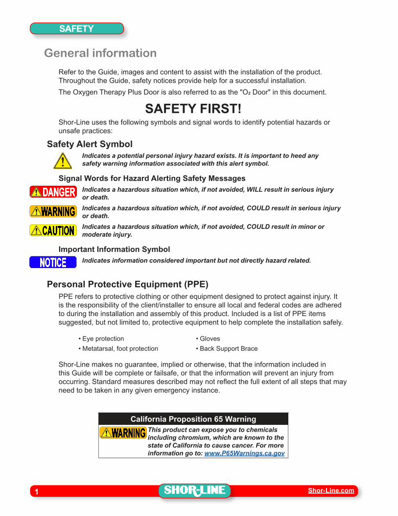
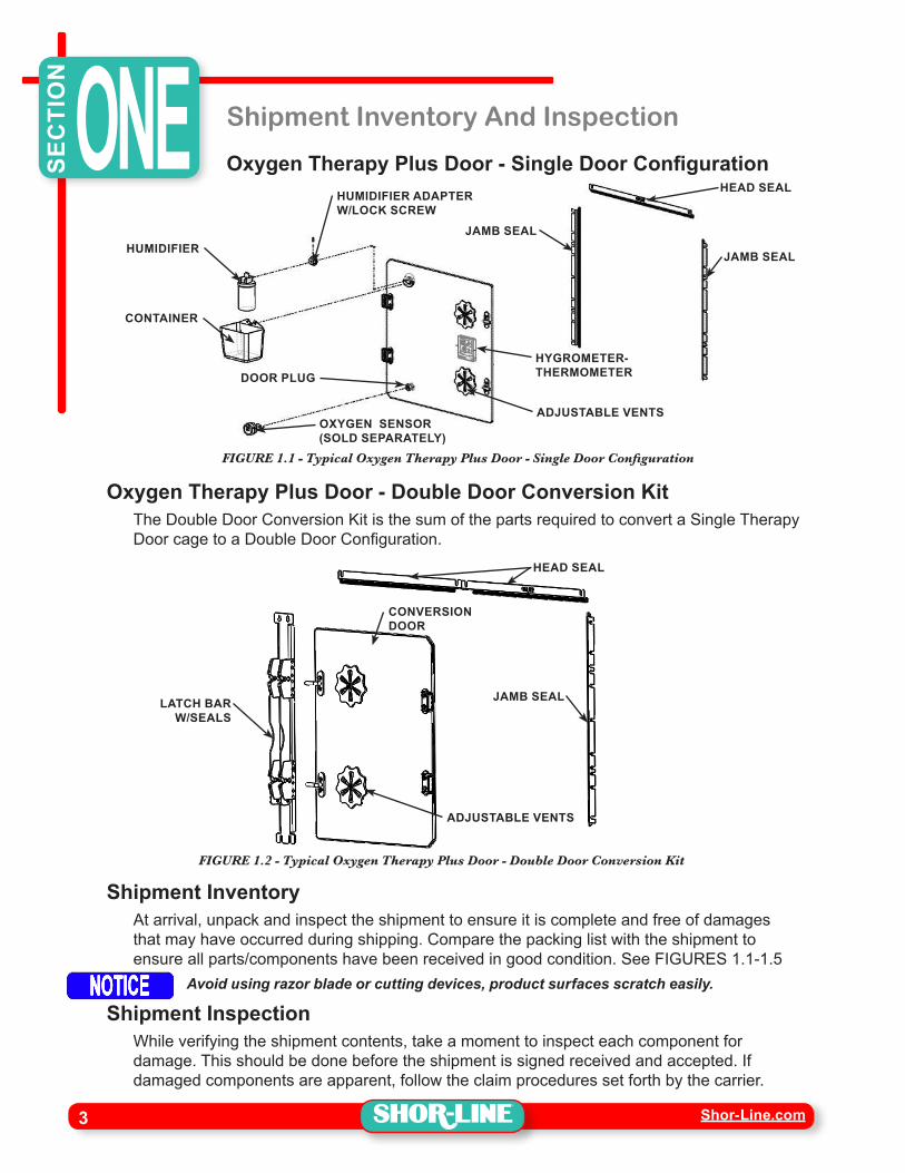
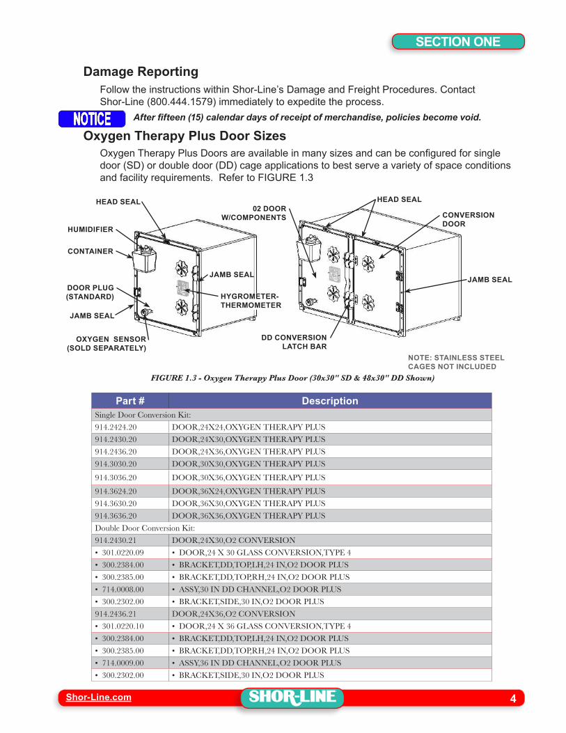
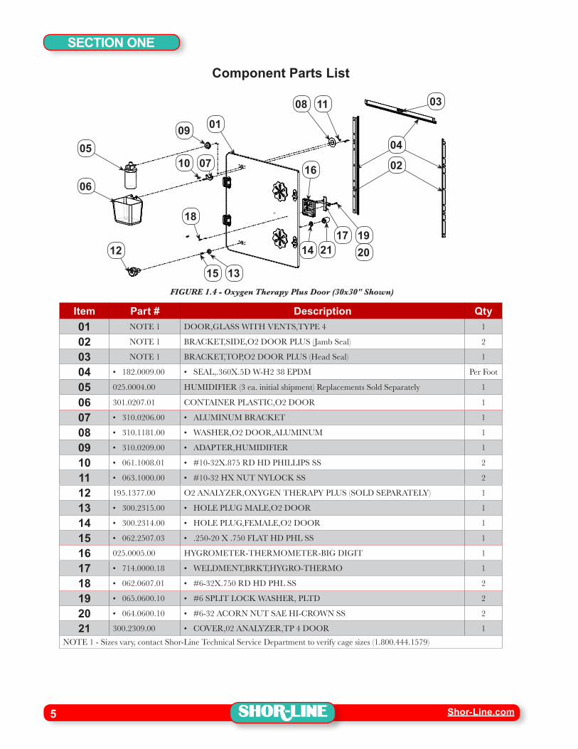
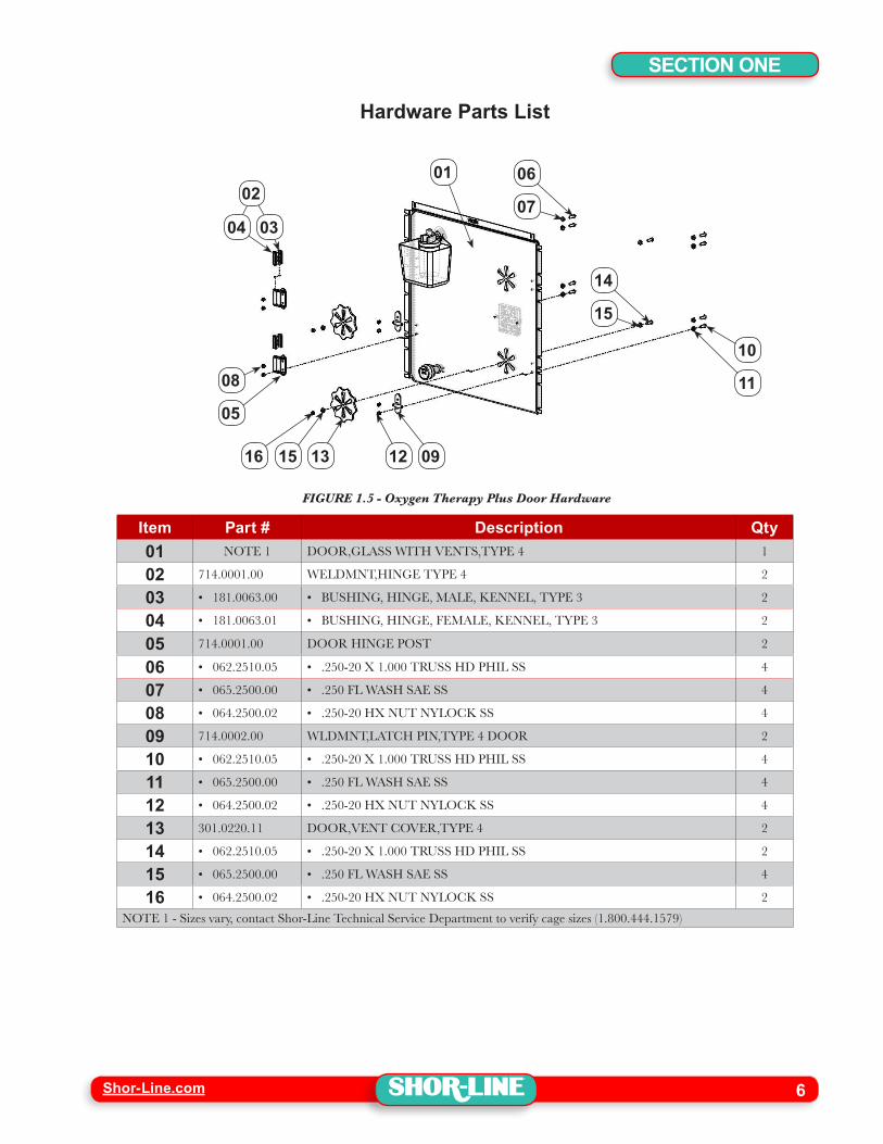
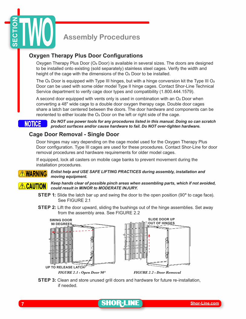
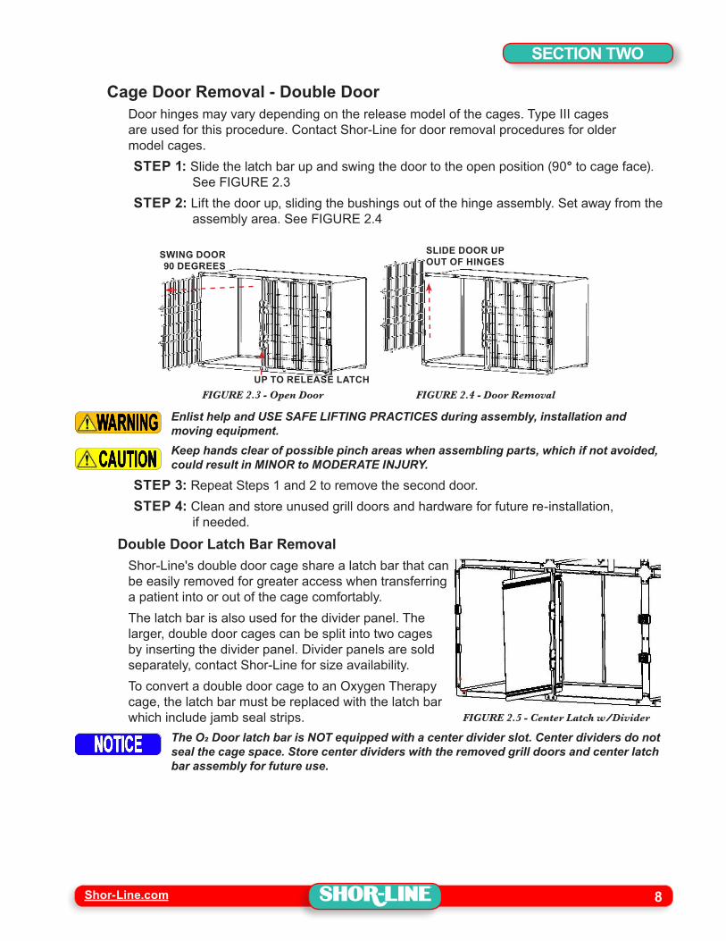
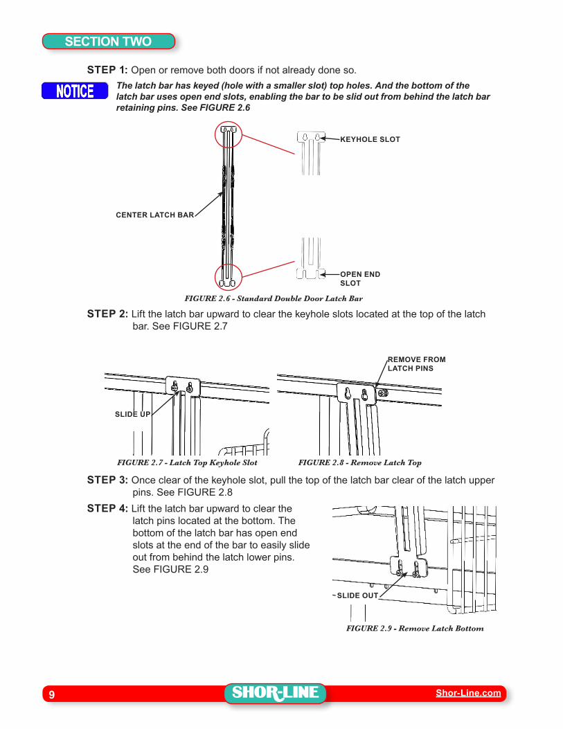
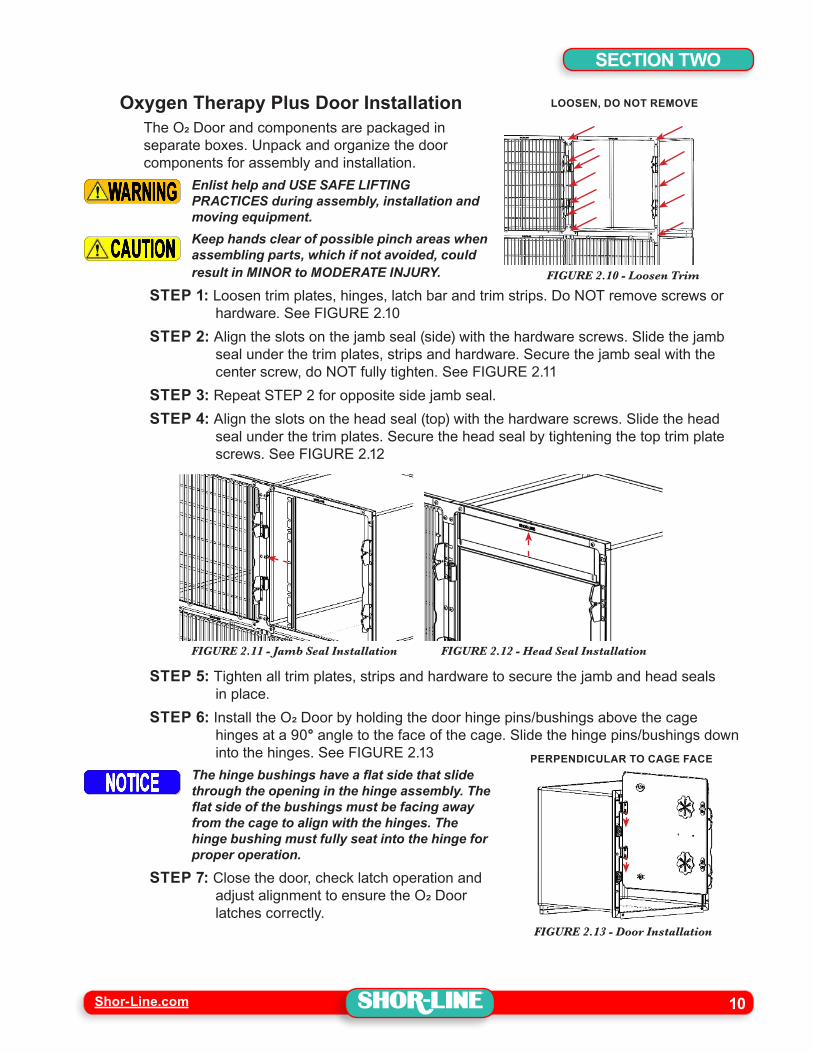
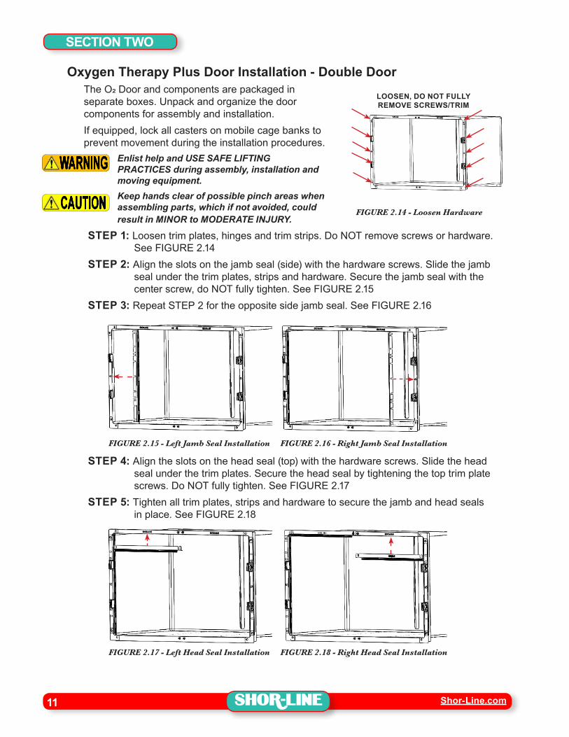
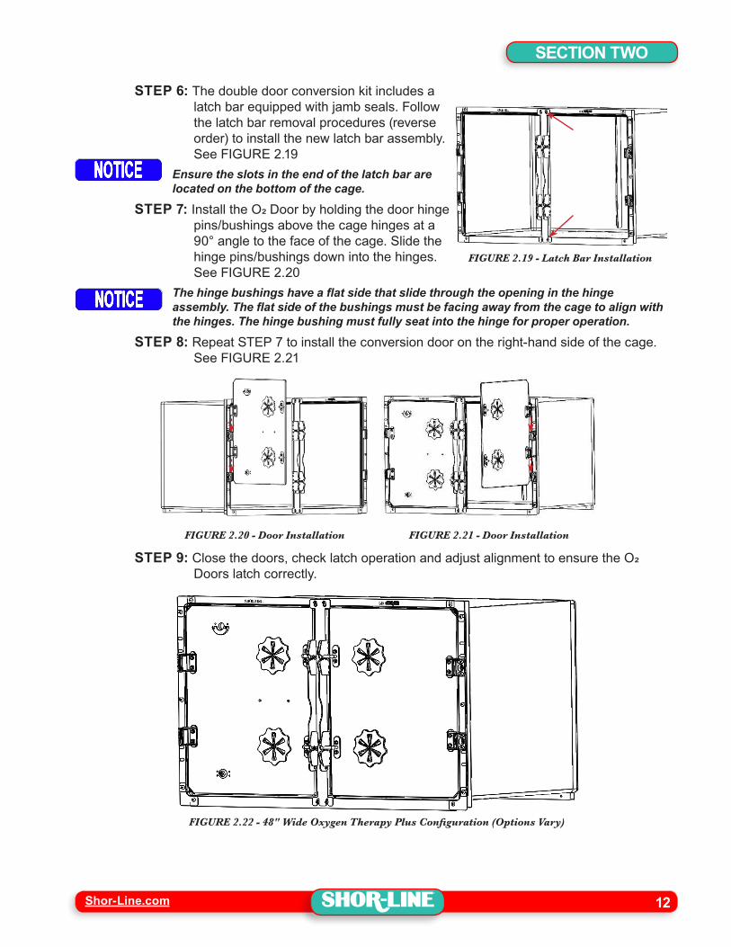
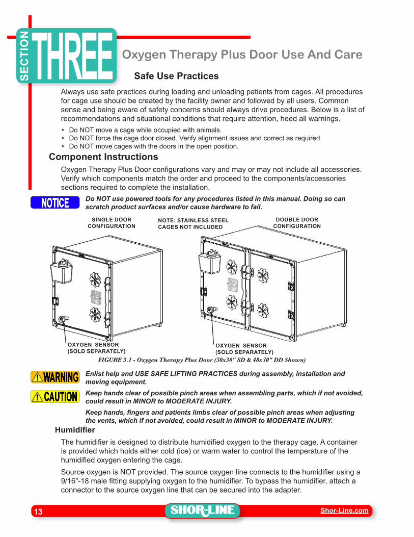
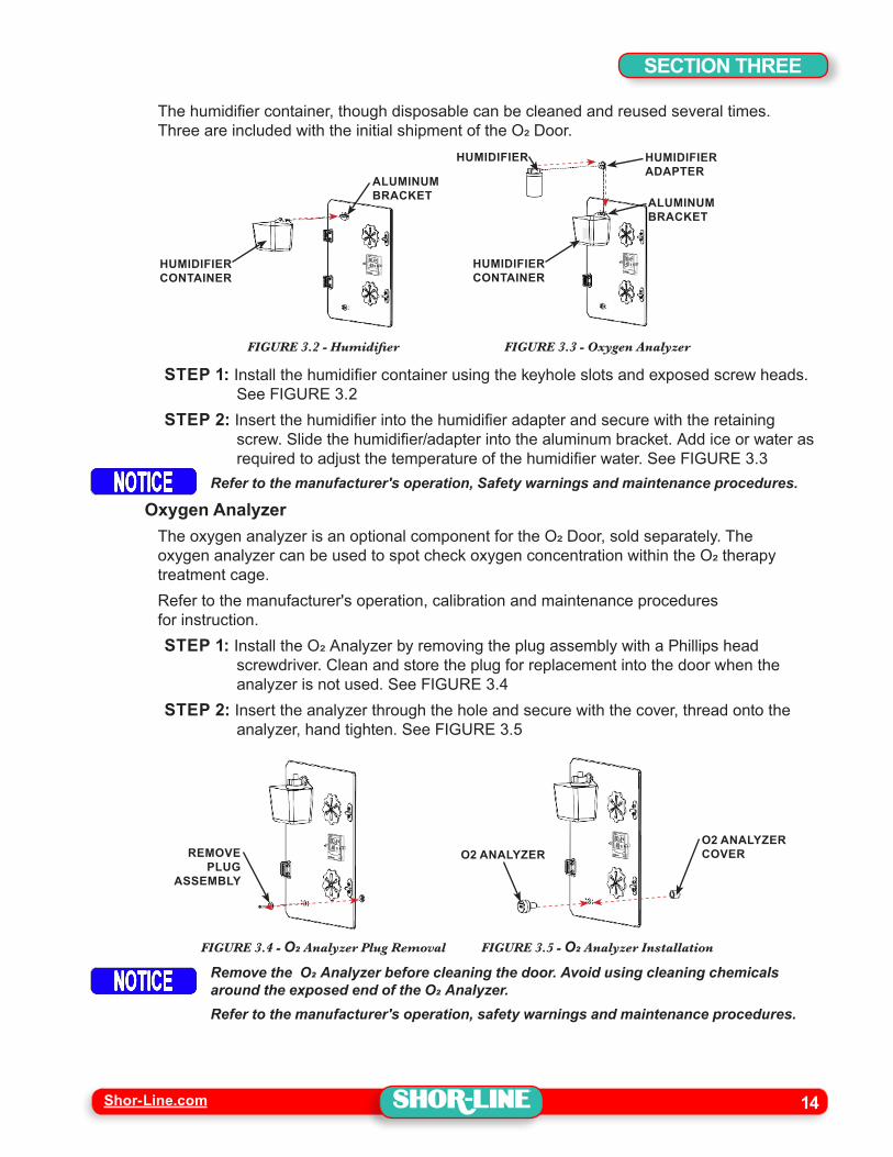
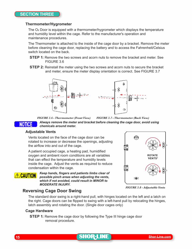
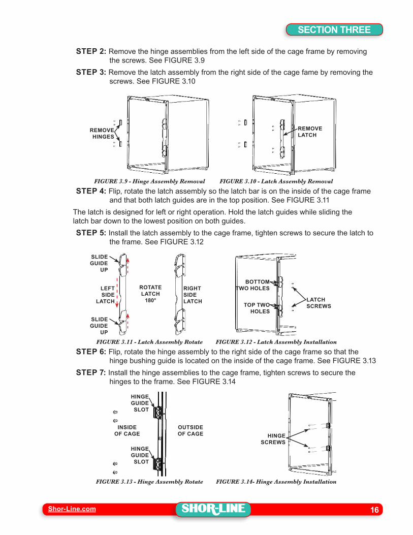
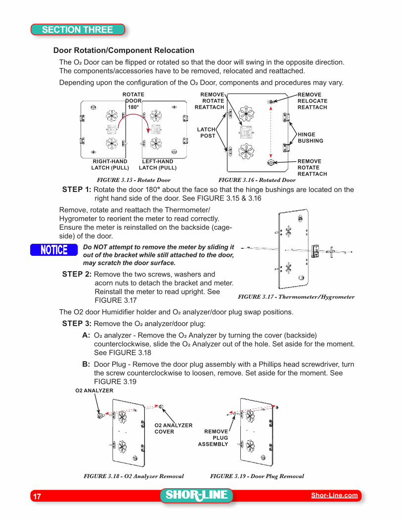
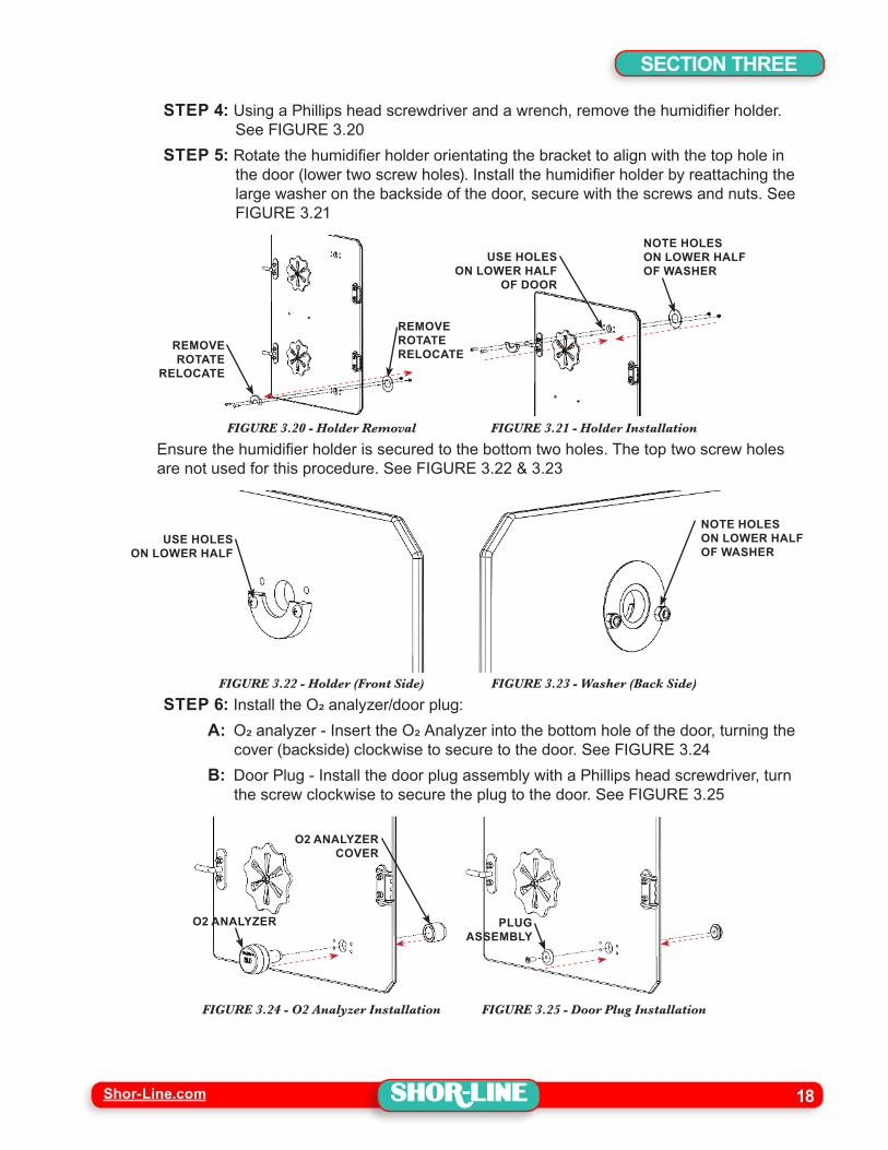
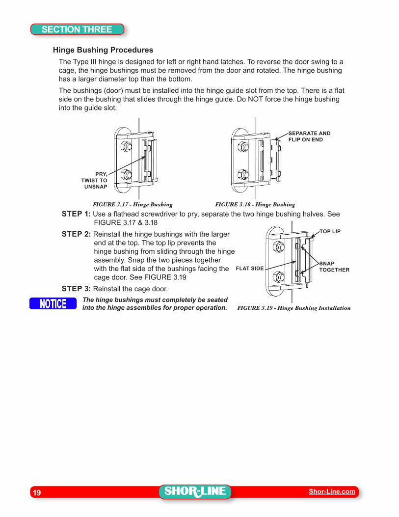
![Acupuntura Pulso Tornozelo 21.2.ppt - portalunisaude.com.br tornozelo - regis.pdf · 0dwhuldo surgx]lgr shor surihvvru º g ² 5hjlqdogr /rughor0dwhuldo surgx]lgr shor surihvvru $](https://img.pdfslide.net/doc/110x75/5e112701a85f816445318770/acupuntura-pulso-tornozelo-212ppt-tornozelo-regispdf-0dwhuldo-surgxlgr.jpg)