Embed Size (px)
Citation preview

5a-1
PART 5a : Worked examples Example to EN 1991 Part 1-2: Compartment fire
P. Schaumann, T. Trautmann University of Hannover – Institute for Steel Construction, Hannover, Germany
1 TASK
The gas temperature of a fully engulfed fire in an office has to be determined. The room of the “Simulated Office” test of the Cardington building is chosen for this analysis. The measured temperatures during the fully engulfed fire are shown in Figure 3, so the calculation can be compared with these results.
A natural fire model is chosen for the calculation of the gas temperature. For fires with a flash-over, the method of the compartment fires can be used. A simple calcula-tion method for a parametric temperature-time curve is given in Annex A of EN 1991-1-2.
Figure 1. Cardington building (left) and the office of the “Simulated Office” test (right)
Floor area: Af = 135 m² Total area of vertical openings: Av = 27 m² Vertical opening factor: αv = 0.2 Horizontal opening factor: αh = 0.0 Height: H = 4.0 m Average window height: heq = 1.8 m (assumption) Lightweight concrete: ρ = 1900 kg/m² c = 840 J/kgK λ = 1.0 W/mK

5a-2
2 DETERMINATION OF FIRE LOAD DENSITY EN 1991-1-2
For the determination of the fire load density the Annex E of EN 1991-1-2 offers a cal-culation model. The design value of the load density may either be given from a na-tional fire load classification of occupancies and/or specific for an individual project by performing a fire load evaluation.
At this example, the second method is chosen.
, , 2f d f k q q nq q m δ δ δ1= ⋅ ⋅ ⋅ ⋅ Annex E.1
where: m the combustion factor δq1 the factor considering the danger of fire activation by size of the compartment δq2 the factor considering the fire activation risk due to the type of occupancy δn the factor considering the different active fire fighting measures The fire load consisted of 20 % plastics, 11 % paper and 69 % wood, so it consisted mainly of cellulosic material. Therefore the combustion factor is:
m = 0.8
The factor δq1 considers the danger of fire activation by size of the compartment, as given in Table 1.
Table 1. Fire activation risk due to the size of the compartment (see EN 1991-1-2, Table E.1)
Compartment floor area Af [m²] ≤ 25 ≤ 250 ≤ 2500 ≤ 5000 ≤ 10,000 Danger of fire activation δq1
1.10 1.50 1.90 2.00 2.13
δq1 = 1.5
A factor δq2 considers the fire activation risk due to the type of occupancy, as given in Table 2.
Table 2. Fire activation risk due to the type of occupancy (see EN 1991-1-2, Table E.1)
Danger of fire activation δq2
Examples of occupancies
0.78 artgallery, museum, swimming pool 1.00 offices, residence, hotel, paper industry 1.22 manufactory for machinery & engines 1.44 chemical laboratory, painting workshop 1.66 manufactory for fireworks or paints
δq2 = 1.5

5a-3
The factor taking the different active fire fighting measures into account is calculated to:
10
1n ni
i
δ δ=
=∏
The factors δni are given in Table 3.
Table 3. Factors δni (see EN 1991-1-2, Table E.2) δni function of active fire fighting measures Automatic fire suppression
Automatic water extinguishing system δn1 0.61
0 1.0 1 0.87
Independent water supplies δn2 2 0.7
Automatic fire detection δn3 By heat or 0.87
Automatic fire detection & alarm δn4 by smoke 0.73
Automatic alarm transmission to fire brigade δn5 0.87
Manual fire suppression Work Fire Brigade δn6 0.61
Off Site Fire Brigade δn7 0.78
Safe access routes δn8 0.9 or 1.0 or 1.5
Fire fighting devices δn9 1.0 or 1.5
Smoke exhaust system δn10 1.0 or 1.5
1.0 0.73 0.87 0.78 1.0 1.0 1.0 0.50δ = ⋅ ⋅ ⋅ ⋅ ⋅ ⋅ =n
For calculating the characteristic fire load, the characteristic fire load has to be deter-mined. It is defined as:
, ,fi k k i ui iQ M H ψ= ⋅ ⋅∑ Annex E.2
where: Mk,i the amount of combustible material [kg] Hui the net calorific value [MJ/kg], see EN 1991-1-2, Table E.3 ψi the optional factor for assessing protected fire loads The total fire loading was equivalent to 46 kg wood/m², so the characteristic fire load is:
( ), 135 46 17.5 1.0 108,675 MJfi kQ = ⋅ ⋅ ⋅ =
The characteristic fire load density is determined to:
, , 108,675 135 805 MJ/m²f k fi k fq Q A= = =
The design value of the fire load density is calculated to:
, 805 0.8 1.5 1.0 0.5
483.0 MJ/m²
= ⋅ ⋅ ⋅ ⋅
=f dq

5a-4
3 CALCULATION OF THE PARAMETRIC TEMPERATURE-TIME CURVE Annex A
It has to be determined if the fully engulfed fire is fuel or ventilation controlled. For this, the opening factor and the design value of the fire load density related to the total surface are needed.
1 2 0.021.8 27 474 0.076 m
0.2eq v tO h A A≥
= ⋅ = ⋅ = ≤
and 2
, , 483.0 135 474 137.6MJ m= ⋅ = ⋅ =t d f d f tq q A A
The determination, if the fire is fuel or ventilation controlled is: 3 3
, lim0.2 10 0.2 10 137.6 0.076 0.362 h > 0.333 ht dq O t− −⋅ ⋅ = ⋅ ⋅ = =
⇒ The fire is ventilation controlled For calculation of the temperature-time curves for the heating and the cooling phase, the b factor is needed. This factor considers the thermal absorptivity for the boundary of enclosure. The density, the specific heat and the thermal conductivity of the bound-ary may be taken at ambient temperature. The floor, the slab and the walls are made of lightweight concrete
2 1 2
100J1900 840 1.0 1263.3 2200m s K
ρ λ≥
= ⋅ ⋅ = ⋅ ⋅ = ≤b c
The temperature-time curve in the heating phase is given by:
( )0.2 * 1.7 * 19 *20 1325 1 0.324 e 0.204 e 0.472 et t tgθ
− ⋅ − ⋅ − ⋅= + ⋅ − ⋅ − ⋅ − ⋅
Because the fire is ventilation controlled, the time t* is calculated to: *t t= ⋅Γ
where:
( )( )
( )( )
2 2
2 2
0.076 1263.33.04
0.04 1160 0.04 1160
O bΓ = = =
Now the heating phase can be calculated: ( ) ( ) ( )( )0.2 3.04 1.7 3.04 19 3.0420 1325 1 0.324 e 0.204 e 0.472 et t t
gθ− ⋅ ⋅ − ⋅ ⋅ − ⋅ ⋅= + ⋅ − ⋅ − ⋅ − ⋅
For calculation of the cooling phase, the maximum temperature is needed.
( )max max max0.2 * 1.7 * 19 *max 20 1325 1 0.324 0.204 0.427t t te e eθ − ⋅ − ⋅ − ⋅= + ⋅ − ⋅ − ⋅ − ⋅
where:
max max*t t= ⋅Γ
The time tmax is determined as below, where tlim is given in Table 4.
3 3,
maxlim
0.2 10 0.2 10 137.6 0.076 0.362 hmax
0.333 ht dq O
tt
− − ⋅ ⋅ = ⋅ ⋅ == =

5a-5
Table 4. Time tlim for different fire growth rates Slow fire growth
rate Medium fire growth rate
Fast fire growth rate
tlim [h] 0.417 0.333 0.250
So t*max is calculated to:
max* 0.362 3.04 1.10 ht = ⋅ =
The maximum temperature is calculated to:
( )0.2 1.10 1.7 1.10 19 1.10max 20 1325 1 0.324 0.204 0.427
958.8 °C
e e eθ − ⋅ − ⋅ − ⋅= + ⋅ − ⋅ − ⋅ − ⋅
=
During the cooling phase, t* and t*max are calculated to:
[ ]* 3.04 ht t t= ⋅Γ = ⋅
( )3max ,* 0.2 10 1.10ht dt q O−= ⋅ ⋅ ⋅Γ =
The temperature-time curve in the cooling phase for t*max ≤ 0.5 is given by:
( )( )
max max625 * *
958.8 625 3.04 1.10 1.0g t t x
t
θ θ= − ⋅ − ⋅
= − ⋅ ⋅ − ⋅
where: tmax > tlim x = 1.0
Combination of the heating and cooling curves leads to the parametric temperature-time curve shown in Figure 2.
Figure 2. Gas temperature of the office calculated by using the parametric temperature-
time curve of the office

5a-6
4 COMPARISON BETWEEN CALCULATION AND FIRE TEST
To compare the calculation with the measured temperatures in the test, the factors δ1, δ2 and δni for calculation of the fire load density have to be set to 1.0 (see Figure 3).
Figure 3. Comparison of measured and calculated temperature-time curves
REFERENCES
EN 1991, Eurocode 1:Actions on structures – Part 1-2: General actions – Actions on structures exposed to fire, Brussels: CEN, November 2002
The Behaviour of multi-storey steel framed buildings in fire, Moorgate: British Steel plc, Swinden Technology Centre, 1998
Valorisation Project: Natural Fire Safety Concept, Sponsored by ECSC, June 2001

5a-7
Example to EN 1991 Part 1-2: Localised fire
P. Schaumann, T. Trautmann University of Hannover – Institute for Steel Construction, Hannover, Germany
1 TASK
The steel temperature of a beam has to be determined. It is part of an underground car park below the shopping mall Auchan in Luxembourg. The beams of the car park are accomplished without any use of fire protection material. The most severe fire scenario is a burning car in the middle of the beam (see Figure 1).
For getting the steel temperature, the natural fire model of a localised fire is used.
Figure 1. Underground car park of the shopping mall Auchan
Figure 2. Static system and cross-section of the beam
5a-8
Diameter of the fire: D = 2.0 m Vertical distance between fire source and ceiling: H = 2.7 m Horizontal distance between beam and flame axis: r = 0.0 m Emissivity of the fire: εf = 1.0 Configuration factor: Φ = 1.0 Stephan Boltzmann constant: σ = 5.56 · 10-8 W/m2K4
Coefficient of the heat transfer: αc = 25.0 W/m²K Steel profile: IPE 550
Section factor: Am/V = 140 1/m Unit mass: ρa = 7850 kg/m³ Surface emissivity: εm = 0.7 Correction factor: ksh = 1.0
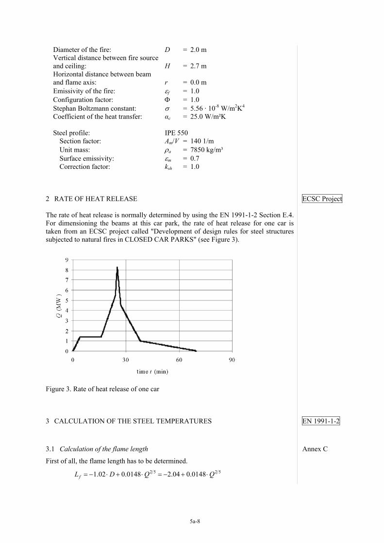
2 RATE OF HEAT RELEASE ECSC Project
The rate of heat release is normally determined by using the EN 1991-1-2 Section E.4. For dimensioning the beams at this car park, the rate of heat release for one car is taken from an ECSC project called "Development of design rules for steel structures subjected to natural fires in CLOSED CAR PARKS" (see Figure 3).
Figure 3. Rate of heat release of one car
3 CALCULATION OF THE STEEL TEMPERATURES EN 1991-1-2
3.1 Calculation of the flame length Annex C
First of all, the flame length has to be determined. 2 5 2 51.02 0.0148 2.04 0.0148fL D Q Q= − ⋅ + ⋅ = − + ⋅

5a-9
A plot of this function with the values of Figure 3 is shown in Figure 4. With a ceiling height of 2.80 m, the flame is impacting the ceiling at a time from 16.9 min to 35.3 min (see Figure 4).
Figure 4. Flame length of the localised fire
It is important to know, if the flame is impacting the ceiling or not, because different calculation methods for the calculation of the net heat flux are used for these two cases (see Figure 5).
Figure 5. Flame models: Flame is not impacting the ceiling (A); Flame is impacting
the ceiling (B)
3.2 Calculation of the net heat flux
3.2.1 1st case: The flame is not impacting the ceiling The net heat flux is calculated according to Section 3.1 of EN 1991-1-2.
( )( ) ( )( ) ( )
( )( ) ( )( ) ( )
4 4
4 48
273 273
25.0 3.892 10 273 273
net c m m f mz z
m mz z
h α θ θ ε ε σ θ θ
θ θ θ θ−
= ⋅ − +Φ ⋅ ⋅ ⋅ ⋅ + − + = ⋅ − + ⋅ ⋅ + − +
&
Section 3.1

5a-10
The gas temperature is calculated to: Annex C
( ) ( ) ( )
( ) ( )
2 3 5 30
5 32 3 2 5
20 0.25 0.8 900 °C
20 0.25 0.8 0.66 0.0052 900 °C
z Q z z
Q Q
θ −
−
= + ⋅ ⋅ ⋅ − ≤
= + ⋅ ⋅ ⋅ − ⋅ ≤
where: z is the height along the flame axis (2.7 m) z0 is the virtual origin of the axis [m]
2 5 2 50 1.02 0.0052 2.04 0.0052z D Q Q= − ⋅ + ⋅ = − + ⋅
3.2.2 2nd case: The flame is impacting the ceiling The net heat flux, if the flame is impacting the ceiling, is given by:
( ) ( ) ( )( )( ) ( ) ( )( )
4 4
4 48
20 273 293
25.0 20 3.892 10 273 293
net c m m f m
m m
h h
h
α θ ε ε σ θ
θ θ−
= − ⋅ − −Φ ⋅ ⋅ ⋅ ⋅ + −
= − ⋅ − − ⋅ ⋅ + −
& &
&
The heat flux depends on the parameter y. For different dimensions of y, different equations for determination of the heat flux have to be used. if y ≤ 0.30:
100,000h =&
if 0.30 < y < 1.0:
136,300 121,000h y= − ⋅&
if y ≥ 1.0: 3.715,000h y−= ⋅&
where:
' 2.7 '' 2.7 'h h
r H z zyL H z L z+ + +
= =+ + + +
The horizontal flame length is calculated to:
( )( ) ( )( )0.33 0.33* *2.9 7.83 2.7h H HL H Q H Q= ⋅ ⋅ − = ⋅ −
where:
( ) ( )* 6 2.5 6 2.51.11 10 1.11 10 2.7HQ Q H Q= ⋅ ⋅ = ⋅ ⋅
The vertical position of the virtual heat source is determined to: if QD
* < 1.0:
( ) ( )( ) ( ) ( )( )2 5 2 3 2 5 2 3* * * *' 2.4 4.8D D D Dz D Q Q Q Q= ⋅ ⋅ − = ⋅ −
if QD* ≥ 1.0:
( )( ) ( )( )2 5 2 5* *' 2.4 1.0 4.8 1.0D Dz D Q Q= ⋅ ⋅ − = ⋅ −
where:
( ) ( )* 6 2.5 6 2.51.11 10 1.11 10 2.0DQ Q D Q= ⋅ ⋅ = ⋅ ⋅

5a-11
3.3 Calculation of the steel temperature-time curve EN 1993-1-2
The specific heat of the steel ca is needed to calculate the steel temperature. The pa-rameter is given by EN 1993-1-2, Section 3.4.1.2 depending on the steel temperature. Section 3.4.1.2
Figure 6. Specific heat of carbon steel (see EN 1993 Part 1-2, Figure 3.4)
4, 1.49 10m
a t m sh net m neta a
A Vk h t hc
θ θ θρ
−= + ⋅ ⋅ ⋅ ∆ = + ⋅ ⋅⋅
& & Section 4.2.5.1
The steel temperature-time curve is shown in Figure 6. Additionally, the results of the FEM-analysis done by PROFILARBED are shown for comparison.
Figure 7. Comparison of the temperature-time curve of the calculation and the FEM-
analysis of PROFILARBED
REFERENCES
EN 1991, Eurocode 1:Actions on structures – Part 1-2: General actions – Actions on structures exposed to fire, Brussels: CEN, November 2002
EN 1993, Eurocode 3: Design of steel structures – Part 1-2: General rules – Struc-tural fire design, Brussels: CEN
ECSC Project, Development of design rules for steel structures subjected to natural fires in CLOSED CAR PARKS, CEC agreement 7210-SA/211/318/518/620/933, Brussels, June 1996

5a-12
Example to EN 1993 Part 1-2: Column with axial loads
P. Schaumann, T. Trautmann University of Hannover – Institute for Steel Construction, Hannover, Germany
1 TASK
In the following example, a column of a department store will be dimensioned for fire resistance. The column is part of a braced frame and is connected bending resistant to the upper and lower column. The length is 3.0 m. During fire exposure, the buckling length can be reduced as seen below in Figure 1. The loads are centric axial compres-sion forces. The column is exposed to fire on four sides. A hollow encasement of gyp-sum is chosen for fire protection. The required standard fire resistance class for the column is R 90.
Figure 1. Buckling lengths of columns in braced frames
Figure 2. Cross-section of the column Material properties:
Column: Profile: rolled section HE 300 B Steel grade: S 235 Cross-section class: 1 Yield stress: fy = 23.5 kN/cm² Cross-sectional area: Aa = 149 cm²

5a-13
Elastic modulus: Ea = 21,000 kN/cm² Moment of inertia: Ia = 8560 cm4 (weak axis)
Encasement: Material: gypsum Thickness: dp = 3.0 cm (hollow encasement) Thermal conductivity: λp = 0.2 W/(m·K) Specific heat: cp = 1700 J/(kg·K) Density: ρp = 945 kg/m³
Loads: Permanent actions: Gk = 1200 kN Variable actions: Pk = 600 kN
2 FIRE RESISTANCE OF COLUMN
2.1 Mechanical actions during fire exposure EN 1991-1-2 The accidental situation is used for the combination of mechanical actions during fire exposure.
( )2, ,dA k d i k iE E G A Qψ= + + ⋅∑ ∑ Section 4.3
The combination factor for department stores is ψ2,1 = 0.6. So the axial load is deter-mined to:
, 1200 0.6 600 1560 kNfi dN = + ⋅ =
2.2 Calculation of the maximum steel temperature EN 1993-1-2 The analysis of EN 1993-1-2 is used to calculate the steel temperature of the hollow encased column. For a hollow encased member, the section factor is calculated to:
( ) 2 -12 ( ) 2 30 30 10 149 81 m= ⋅ + = ⋅ + ⋅ =p aA V b h A Section 4.2.5.2
By using the Euro-Nomogram (ECCS No.89), the maximal temperature θa,max,90 of the steel bar is:
( ) ( ) 381 0.2 0.03 540W m K⋅ = ⋅ =p p pA V dλ ECCS No.89
⇒ θa,max,90 ≈ 445 °C
2.3 Verification in the temperature domain EN 1993-1-2 Within EN 1993-1-2 the verification in the temperature domain is not allowed for members in which stability phenomena have to be taken into account. Section 4.2.4
2.4 Verification in the strength domain The verification in the strength domain during fire exposure is carried out as a plastic ultimate state of the load-carrying capacity.
, , , ,fi d t fi d tE R≤ Section 2.4.2
In this example, the verification has to be done with the axial forces.
, , , ,fi d b fi t RdN N≤
The design resistance under high temperature conditions is calculated as:

5a-14
, , , , ,max,
= ⋅ ⋅ ⋅ yb fi t Rd fi a y
M fi
fN A k θχ
γ Section 4.2.3.2
In dependence of θa,max,90 the reduction factors ky,θ and kE,θ are given in Table 3.1 of the EN 1993-1-2. For intermediate values of the steel temperature, linear interpolation may be used.
⇒ ky,445°C = 0.901 Section 3.2.1
kE,445°C = 0.655 The load-carrying capacity is determined in consideration of the non-dimensional slenderness during fire exposure.
, , , 0.21 0.901 0.655 0.25= ⋅ = ⋅ =fi y Ek kθ θ θλ λ Section 4.2.3.2
where: EN 1993-1-1
( ) ( ) ( )0.5 300 7.58 93.9 0.21= ⋅ = ⋅ ⋅ =Kz z aL iλ λ Section 6.3.1.3
With the non-dimensional slenderness the reduction factor for flexural buckling χfi,θ can be calculated. EN 1993-1-2
2 2 2 2
1 1 0.86- 0.61 0.61 - 0.14
= = =+ +
fiχϕ ϕ λ
Section 4.2.3.2
where: 2 2 0.5 1 0.5 1 0.65 0.25 0.25 0.61 = ⋅ + ⋅ + = ⋅ + ⋅ + = ϕ α λ λ
and:
0.65 235 0.65 235 235 0.65yfα = ⋅ = ⋅ =
The design resistance arises to:
, , ,23.50.86 149 0.901 2713 kN1.0
= ⋅ ⋅ ⋅ =b fi t RdN
Verification:
, , , , 1560 2713 0.58 1= = <fi d b fi t RdN N
REFERENCES
ECCS No.89, Euro-Nomogram, Brussels: ECCS – Technical Committee 3 – Fire Safety of Steel Structures, 1995 EN 1991, Eurocode 1:Actions on structures – Part 1-2: General actions – Actions on struc-tures exposed to fire, Brussels: CEN, November 2002 EN 1993, Eurocode 3: Design of steel structures – Part 1-1: General rules, Brussels: CEN, May 2002 EN 1993, Eurocode 3: Design of steel structures – Part 1-2: General rules – Structural fire de-sign, Brussels: CEN, November 2003

5a-15
Example to EN 1993 Part 1-2: Beam with bending and compression loads
P. Schaumann, T. Trautmann University of Hannover – Institute for Steel Construction, Hannover, Germany
1 TASK
This example deals with a beam subjected to a uniform load, which causes bending moment, and an axial load. Stability phenomena have to be considered. The beam is part of an office building. A hollow encasement of gypsum is chosen for fire protec-tion. Due to a concrete slab the beam is exposed to fire on three sides. There is no shear-connection between the beam and the slab. The required standard fire resistance class for the beam is R 90.
Figure 1. Static system
Figure 2. Beam Cross-section Material properties: Beam: Profile: rolled section HE 200 B Steel grade: S 235 Cross-section class: 1 Yield stress: fy = 235 N/mm² Elastic modulus: E = 210,000 N/mm² Shear modulus: G = 81,000 N/mm² Cross-sectional area: Aa = 7810 mm² Moment of inertia: Iz = 2000 cm4 Torsion constant: It = 59.3 cm4
5a-16
Warping constant: Iw = 171,100 cm6 Section moduli: Wel,y = 570 cm² Wpl,y = 642.5 cm³ Encasement: Material: gypsum Thickness: dp = 20 mm (hollow encasement) Thermal conductivity: λp = 0.2 W/(m·K) Specific heat: cp = 1700 J/(kg·K) Density: ρp = 945 kg/m³ Loads: Permanent Loads: Gk = 96.3 kN gk = 1.5 kN/m Variable Loads: pk = 1.5 kN/m
2 FIRE RESISTANCE OF BEAM WITH BENDING AND COMPRESSION LOADS
2.1 Mechanical actions during fire exposure EN 1991-1-2
The combination of mechanical actions during fire exposure shall be calculated as an accidental situation:
( )2, ,dA k d i k iE E G A Qψ= + + ⋅∑ ∑ Section 4.3
The combination factor for office buildings is ψ2,1 = 0.3. The design loads under high temperature conditions are:
, 96.3 kNfi dN =
[ ]2
,10.01.5 0.3 1.5 24.38 kNm
8fi dM = + ⋅ ⋅ =
2.2 Calculation of steel temperatures prEN 1993-1-2
The steel temperature is given by the Euro-Nomogram (ECCS No.89). Therefore the section factor Ap/V is needed. For a hollow encased member exposed to fire on three sides, the section factor is:
2 -12 2 20.0 20.0 10 77 m78.1
p
a
A h bV A
⋅ + ⋅ += = ⋅ = Section 4.2.5.2
With
30.2 W77 770
0.02 m Kp p
p
AV d
λ⋅ = ⋅ =
⋅, ECCS No.89
the critical temperature arises to:
⇒ θa,max,90 ≈ 540 °C

5a-17
2.3 Verification in the temperature domain prEN 1993-1-2
Due to section 4.2.4 (2) of prEN 1993-1-2 the verification in the temperature domain may not be accomplished, because of stability problems of the beam. Section 4.2.4
2.4 Verification in the strength domain
Members with a Class 1 cross-section should be analysed for the problem of flexural buckling and of lateral torsional buckling.
2.4.1 Flexural buckling The verification for flexural buckling is:
, , ,
min, , , , , ,1fi d y y fi d
fi y y M fi pl y y y M fi
N k MA k f W k fθ θχ γ γ
⋅+ ≤
⋅ ⋅ ⋅ ⋅ ⋅ Section 4.2.3.5
The reduction factor χmin,fi is the minimum of the two reduction factors for flexural buckling χy,fi and χz,fi. The non-dimensional slenderness for the temperature θa is needed for the calculation of these reduction factors.
For calculation of the non-dimensional slenderness in the fire situation, the non-dimensional slenderness at ambient temperatures have to be determined. prEN 1993-1-1
1000 1.258.54 93.9
cry
y a
Li
λλ
= = =⋅ ⋅
Section 6.3.1.3
1000 2.105.07 93.9
crz
z a
Li
λλ
= = =⋅ ⋅
The needed reduction factors ky,θ and kE,θ are given in prEN 1993-1-2 Table 3.1: prEN 1993-1-2
⇒ ky,θ = 0.656 Section 3.2.1
kE,θ = 0.484 With the reduction factors, the non-dimensional slenderness in the fire situation can be determined:
,,
,
0.6561.25 1.460.484
yy y
E
kk
θθ
θ
λ λ= = = Section 4.2.3.2
,,
,
0.6562.1 2.440.484
yz z
E
kk
θθ
θ
λ λ= = =
With
0.65 235 0.65 235 235 0.65yfα = ⋅ = ⋅ =
and
( ) ( )2 2, , ,
1 11 1 0.65 1.46 1.46 2.042 2y y yθ θ θϕ α λ λ= ⋅ + ⋅ + = ⋅ + ⋅ + = ,
( ) ( )2 2, , ,
1 11 1 0.65 2.44 2.44 4.272 2z z zθ θ θϕ α λ λ= ⋅ + ⋅ + = ⋅ + ⋅ + =

5a-18
the reduction factors χy,fi and χz,fi can be calculated:
, 2 2 2 2, , ,
1 1 0.292.04 2.04 1.46
y fiy y yθ θ θ
χϕ ϕ λ
= = =+ − + −
, 2 2 2 2, , ,
1 1 0.134.27 4.27 2.44
z fiz z zθ θ θ
χϕ ϕ λ
= = =+ − + −
Verification:
96.3 1.33 2438 0.94 10.13 78.1 0.656 23.5 642.5 0.656 23.5
⋅+ = <
⋅ ⋅ ⋅ ⋅ ⋅ Section 4.2.3.5
where:
( )( )
, , ,1.2 3 0.44 0.29
1.2 1.3 3 1.46 0.44 1.3 0.29 1.82
y M y y M yθµ β λ β= ⋅ − ⋅ + ⋅ −
= ⋅ − ⋅ + ⋅ −
= −
,
, ,
1.82 96.31 1 1.330.29 78.1 23.5 1.0
y fi dy
y fi a y m fi
Nk
A fµ
χ γ⋅ − ⋅
= − = − =⋅ ⋅ ⋅ ⋅
2.4.2 Lateral torsional buckling The second verification deals with the problem of lateral torsional buckling.
, , ,
, , , , , , ,1fi d LT y fi d
z fi y y M fi LT fi pl y y y M fi
N k MA k f W k fθ θχ γ χ γ
⋅+ ≤
⋅ ⋅ ⋅ ⋅ ⋅ ⋅
For calculation of the non-dimensional slenderness in the fire situation, the non-dimensional slenderness at ambient temperatures has to be determined prEN 1993-1-1
, 642.5 23.5 1.0514,420.4
pl y yLT
cr
W fM
λ⋅ ⋅
= = = Section 6.3.2.2
where:
( )( ) ( )
2 22 21 2 22 2
twzcr g g
w z z
k L G IIE I kM C C z C zk I E Ik L
ππ
⋅ ⋅ ⋅ ⋅ ⋅ = ⋅ ⋅ + + ⋅ − ⋅ ⋅ ⋅⋅
Section C.2.2
( )
( )
2
2
22 2
2
21,000 2000 1.121.0 1000
1.0 1000 8100 59.31.0 171,100 20 20 0.45 0.451.0 2000 2 221,000 2000
π
π
⋅ ⋅= ⋅ ⋅
⋅
⋅ ⋅ ⋅ + + ⋅ − ⋅ ⋅ ⋅
14,420.4 kNcm=
During fire exposure, the non-dimensional slenderness changes to: prEN 1993-1-2
,,
,
0.6561.02 1.190.484
yLT LT
E
kk
θθ
θ
λ λ= ⋅ = ⋅ = Section 4.2.3.3
With

5a-19
( ) ( )2 2, , ,
1 11 1 0.65 1.19 1.19 1.592 2LT LT LTθ θ θφ α λ λ= ⋅ + ⋅ + = ⋅ + ⋅ + = ,
the reduction factor χLT,fi is calculated to:
, 2 2 2 2, , ,
1 1 0.381.59 1.59 1.19
LT fiLT LT LTθ θ θ
χφ φ λ
= = =+ − + −
Verification:
96.3 0.20 24380.13 78.1 0.656 23.5 1.0 0.38 642.5 0.656 23.5 1.0
⋅+
⋅ ⋅ ⋅ ⋅ ⋅ ⋅ Section 4.2.3.5
0.60 0.13 0.73 1= + = ≤
where:
,
, , ,
0.33 93.3 0.200.13 78.1 0.656 23.5 1.0
LT fi dLT
z fi y y M fi
Nk
A k fθ
µχ γ
⋅ ⋅= = =
⋅ ⋅ ⋅ ⋅ ⋅ ⋅
, ,0.15 0.15 0.9 0.15 2.44 1.3 0.15 0.33 0.9
LT z M LTθµ λ β= ⋅ ⋅ − <
= ⋅ ⋅ −= <
REFERENCES
ECCS No.89, Euro-Nomogram, Brussels: ECCS – Technical Committee 3 – Fire Safety of Steel Structures, 1995 EN 1991, Eurocode 1:Actions on structures – Part 1-2: General actions – Actions on structures exposed to fire, Brussels: CEN prEN 1993, Eurocode 3: Design of steel structures – Part 1-1: General rules, Brus-sels: CEN, May 2002 prEN 1993, Eurocode 3: Design of steel structures – Part 1-2: General rules – Struc-tural fire design, Brussels: CEN

5a-20
Example to EN 1993 Part 1-2: Beam made of a hollow section
P. Schaumann, T. Trautmann University of Hannover – Institute for Steel Construction, Hannover, Germany
1 TASK
At this example, a beam made of a welded hollow section has to be dimensioned. It is part of a hall roof structure. The length of the beam is 35.0 m and the beams are ar-ranged at a distance of 10.0 m. It is charged with uniform loads and is restrained against lateral evasion. The beam is executed without any use of fire protection mate-rial. The required standard fire resistance class for the tensile bar is R 30.
Figure 1. Static system
Figure 2. Cross-section Material properties:
Steel grade: S 355 Yield stress: fy = 355 N/mm² Height: h = 700 mm Height of web: hw = 650 mm Width: b = 450 mm Thickness of flange: tf = 25 mm Thickness of web: tw = 25 mm Cross-sectional area of the flange: Af = 11,250 mm²

5a-21
Cross-sectional area of the web: Aw = 16,250 mm² Specific heat: ca = 600 J/(kg·K) Density: ρa = 7850 kg/m³ Emissivity of the beam: εm = 0.7
Emissivity of the fire: εr = 1.0 Configuration factor Φ = 1.0 Coefficient of the heat transfer: αc = 25.0 W/m²K Stephan Boltzmann constant: σ = 5.67 · 10-8 W/m²K4 Loads: Permanent actions:
Beam: ga,k = 4.32 kN/m Roof: gr,k = 5.0 kN/m
Variable actions: Snow: ps,k = 11.25 kN/m
2 FIRE RESISTANCE OF BEAM MADE OF A HOLLOW SECTION
2.1 Mechanical actions during fire exposure EN 1991-1-2
The accidental situation is used for the combination of mechanical actions during fire exposure.
( )2, ,dA k d i k iE E G A Qψ= + + ⋅∑ ∑ Section 4.3
The combination factor for snow loads is ψ2,1 = 0.0. With this parameter, the design bending load is calculated to:
( )2
,35.04.32 5.0 0.0 11.25 1427.1 kNm
8fi dM = + + ⋅ ⋅ =
2.2 Calculation of the steel temperature EN 1993-1-2
The temperature increase of the steel section is calculated to: Section 4.2.5.1
5, ,
401.0 5 4.25 10600 7850
ma t sh net d net net
a a
A Vk h t h hc
θρ
−∆ = ⋅ ⋅ ⋅ ∆ = ⋅ ⋅ ⋅ = ⋅ ⋅⋅ ⋅
& & &
where: ksh correction factor for the shadow effect (ksh = 1.0) ∆t time interval (∆t = 5 seconds) Am/V section factor for the unprotected beam
1 1 0.025 40 1 mmA V t= = =
The net heat flux is calculated according to EN 1991 Part 1-2. EN 1991-1-2
( ) ( ) ( )( )( ) ( ) ( )( )
4 4
4 48
273 273
25 3.969 10 273 273
net c g m m r g m
g m g m
h α θ θ ε ε σ θ θ
θ θ θ θ−
= ⋅ − +Φ ⋅ ⋅ ⋅ ⋅ + − +
= ⋅ − + ⋅ ⋅ + − +
&
Section 3.1
The standard temperature-time curve is used for getting the gas temperatures.
( )1020 345 log 8 1g tθ = ⋅ ⋅ ⋅ + Section 3.2.1

5a-22
The steel temperature-time curve of the hollow section is shown in Figure 3:
Figure 3. Steel temperature-time curve of the hollow section
⇒ θa,max,30 = 646 °C
2.3 Verification in the temperature domain EN 1993-1-2
The design moment resistance during fire exposure at the time t = 0 is needed to get the utilization factor.
, ,0 , ,max ,fi Rd pl y y M fiM W f k θ γ= ⋅ ⋅ Section 4.2.3.3
61.0 12,875,000 355 101.0
4570.6 kNm
−= ⋅ ⋅ ⋅
=
where: ky,θ,max = 1.0 for θ = 20 °C at the time t = 0 γM,fi = 1.0 and:
3
222 4 2
650 700 25 2 16,250 11,2504 2
12,875,000 mm
⋅ − = ⋅ ⋅ + ⋅
− = ⋅ ⋅ + ⋅
=
w w wpl f
A h h tW A
The utilization factor is calculated to:
0 , , ,0 , , ,0 1427.1 4570.6 0.31= = = =fi d fi d fi d fi RdE R M Mµ Section 4.2.4
The critical temperature θa,cr is given in Table 4.1 of the EN 1993 Part 1-2.
⇒ θa,cr = 659 °C Verification:
646 0.98 1659
= <

5a-23
2.4 Verification in the strength domain
To calculate the moment resistance the reduction factor ky,θ has to be determined for the temperature θa,max,30 = 646 °C. This factor is given in Table 3.1 of the EN 1993 Part 1-2:
ky,θ = 0.360 Section 3.2.1 Additionally, the adaptation factors κ1 and κ2 have to be determined.
The adaptation factor κ1 considers the non-uniform temperature distribution across the cross-section. Table 1. Adaptation factor κ1 Section 4.2.3.3
κ1 [-] Beam exposed on all four sides 1.0 Unprotected beam exposed on three sides with a composite or concrete slab on side four 0.7
Protected beam exposed on three sides with a composite or concrete slab on side four 0.85
The beam in this is an unprotected beam exposed to fire on four sides. Therefore κ1 is set to:
κ1 = 1.0 The adaptation factor κ2 considers the non-uniform temperature distribution along a beam. Table 2. Adaptation factor κ2
κ2 [-] At the supports of a statically indeterminate beam 0.85 In all other cases 1.0
The verification is done in the middle of the beam and it is statically determinate. So the adaptation factor κ2 is set to:
κ2 = 1.0 Therefore the design moment resistance is calculated to:
( )
,1, , , ,20 ,
, 1 2
6
1
1.1 1 12,87,000 355 1.1 0.36 10 1645.4 kNm1.0 1.0 1.0
°
−
= ⋅ ⋅ ⋅⋅
= ⋅ ⋅ ⋅ ⋅ ⋅ =⋅
Mfi t Rd pl Rd C y
M fi
M M k θ
γγ κ κ
Verification:
1427.1 0.87 11645.4
= <
REFERENCES
EN 1991, Eurocode 1:Actions on structures – Part 1-2: General actions – Actions on structures exposed to fire, Brussels: CEN, November 2002 EN 1993, Eurocode 3: Design of steel structures – Part 1-2: General rules – Struc-tural fire design, Brussels: CEN

5a-24
Example to EN 1994 Part 1-2: Composite slab
P. Schaumann, T. Trautmann University of Hannover – Institute for Steel Construction, Hannover, Germany
1 TASK
A composite slab has to be dimensioned in the fire situation. It is part of a shopping centre and the span is 4.8 m. The slab will be dimensioned as a series of simply sup-ported beams. The required standard fire resistance class for the slab is R 90.
Figure 1. Static system
Figure 2. Steel sheet
Material properties Steel sheet:
Yield stress: fyp = 350 N/mm² Cross-sectional area: Ap = 1562 mm²/m Parameters for m+k method: k = 0.150 N/mm²
Concrete: Strength category: C 25/30 Compression strength: fc = 25 N/mm² Height: ht = 140 mm Cross-sectional area: Ac = 131,600 mm²/m

5a-25
Scope of application for re-entrant profiles [mm]
Existing geometrical parameters [mm]
77.0 ≤ l1 ≤ 135.0 l1 = 115.0 110 ≤ l2 ≤ 150.0 l2 = 140.0 38.5 ≤ l3 ≤ 97.5 l3 = 38.0 50.0 ≤ h1 ≤ 130.0 h1 = 89.0 30.0 ≤ h2 ≤ 70.0 h2 = 51.0
Loads:
Permanent loads: Steel sheet gp,k = 0.13 kN/m² Concrete: gc,k = 3.29 kN/m² Finishing load: gf,k = 1.2 kN/m²
Variable loads: Live load: pk = 5.0 kN/m²
Design sagging moment at ambient temperatures: Ms,d = 39.56 kNm
2 FIRE RESISTANCE OF A COMPOSITE SLAB
The composite slab has to be verified according to Section 4.3 and Annex D.
2.1 Geometrical parameters and scope of application
Figure 3. Geometry of cross-section
h1 = 89 mm h2 = 51 mm l1 = 115 mm l2 = 140 mm l3 = 38 mm Table 1. Scope of application for slabs made of normal concrete and re-entrant steel
sheets Scope of application for re-entrant profiles [mm]
Existing geometrical parameters [mm]
77.0 ≤ l1 ≤ 135.0 l1 = 115.0 110 ≤ l2 ≤ 150.0 l2 = 140.0 38.5 ≤ l3 ≤ 97.5 l3 = 38.0 50.0 ≤ h1 ≤ 130.0 h1 = 89.0 30.0 ≤ h2 ≤ 70.0 h2 = 51.0
2.2 Mechanical actions during fire exposure EN 1991-1-2
The load is determined by the combination rule for accidental situations.
( )2, ,dA k d i k iE E G A Qψ= + + ⋅∑ ∑ Section 4.3
According to EN 1994 Part 1-2, the load Ed may be reduced by the reduction EN 1994-1-2

5a-26
factor ηfi. It is calculated to:
( )( )
2,1 ,1
,1 ,1
0.13 3.29 1.2 0.6 5.00.55
1.35 0.13 3.29 1.2 1.5 5.0+ ⋅ + + + ⋅
= = =⋅ + ⋅ ⋅ + + + ⋅k k
fiG k Q k
G QG Q
ψη
γ γ Section 2.4.2
With ηfi, the design bending moment Mfi,d can be calculated:
, 0.55 39.56 21.94 kNm/m= ⋅ = ⋅ =fi d fi sdM Mη
2.3 Thermal insulation Section D.1
The thermal insulation criteria “I” has to ensure the limitation of the thermal condition of the member. The temperature on top of the slab should not exceed 140 °C in aver-age and 180 °C at its maximum.
The verification is done in the time domain. The time in which the slab fulfils the criteria “I” is calculated to:
0 1 1 2 3 4 53 3
1 1i
r r
A At a a h a a a aL l L l
= + ⋅ + ⋅Φ + ⋅ + ⋅ + ⋅ ⋅
The rib geometry factor A/Lr is equivalent to the section factor Ap/V for beams. The factor considers that the mass and height have positive effects on the heating of the slab.
Figure 4. Definition of the rib geometry factor
1 22
2 222 1 2
2 2
115 140522 2 27 mm
115 140140 2 51222
r
l lhAL l ll h
+ + ⋅ ⋅ = = =
− − + ⋅ ++ ⋅ +
The view factor Φ considers the shadow effect of the rib on the upper flange.
2 22 21 2 1 2
2 3 2 3
2 22 2
2 2
115 140 115 140 51 38 51 382 2
0.119
l l l lh l h l − − Φ = + + − + + − − = + + − +
=
The coefficients ai for normal weight concrete is given in Table 2:
Lr

5a-27
Table 2. Coefficients for determination of the fire resistance with respect to thermal insulation (see EN 1994-1-2, Annex D, Table D.1)
a0 [min]
a1 [min/mm]
a2 [min]
a3 [min/mm]
a4 mm·min
a5 [min]
Normal weight concrete -28.8 1.55 -12.6 0.33 -735 48.0 Light weight concrete -79.2 2.18 -2.44 0.56 -542 52.3
With these parameters, ti is calculated to:
( ) ( )( )
28.8 1.55 89 12.6 0.119
0.33 27 735 1 38 48 27 1 38
= − + ⋅ + − ⋅
+ ⋅ + − ⋅ + ⋅ ⋅it
131.48 min 90 min= >
2.4 Verification of the load carrying-capacity Section 4.3.2
The plastic moment design resistance is calculated to:
, ,, , , , , ,
, , ,
y i c jfi t Rd i i y i slab j j c j
M fi M fi c
f fM A z k A z kθ θα
γ γ
= ⋅ ⋅ ⋅ + ⋅ ⋅ ⋅ ⋅
∑ ∑
To get the reduction factors ky,θ for the upper flange, lower flange and the web, the temperatures have to be determined. These are calculated to:
20 1 2 3 4
3
1a
r
Ab b b b bl L
θ = + ⋅ + ⋅ + ⋅Φ + ⋅Φ Section D.2
The coefficients bi can be obtained from Table 3:
Table 3. Coefficients for the determination of the temperatures of the parts of the steel decking (see EN 1994-1-2, Annex D, Table D.2)
Concrete Fire
resistance [min]
Part of steel sheet
b0 [°C]
b1 [°C·mm]
b2 [°C/mm] b3 [°C] b4 [°C]
Lower flange 951 -1197 -2.32 86.4 -150.7
60 Web 661 -833 -2.96 537.7 -351.9
Upper flange 340 -3269 -2.62 1148.4 -679.8
Lower flange 1018 -839 -1.55 65.1 -108.1
90 Web 816 -959 -2.21 464.9 -340.2
Upper flange 618 -2786 -1.79 767.9 -472.0
Lower flange 1063 -679 -1.13 46.7 -82.8
120 Web 925 -949 -1.82 344.2 -267.4
Normal weight
concrete
Upper flange 770 -2460 -1.67 592.6 -379.0
For the different parts of the steel sheet, the temperatures are: Lower flange:
2,
11018 839 1.55 27 65.1 0.119 108.1 0.11938
960.29 °C
a lθ = − ⋅ − ⋅ + ⋅ − ⋅
=

5a-28
Web:
2,
1816 959 2.21 27 464.9 0.119 340.2 0.11938
781.60 °C
a wθ = − ⋅ − ⋅ + ⋅ − ⋅
=
Upper flange:
2,
1618 2786 1.79 27 767.9 0.119 472.0 0.11938
580.87 °C
a lθ = − ⋅ − ⋅ + ⋅ − ⋅
=
To get the required load carrying-capacity during fire exposure, reinforcing bars have to be installed which normally are neglected for the ambient temperature design. For each rib, one reinforcing bar Ø 10 mm is chosen. The position of the bar can be seen in Figure 5.
Figure 5. Arrangement of the reinforcing bar
The temperature of the reinforcing bar is calculated to:
30 1 2 3 4 5
2 3
1s
r
u Ac c c z c c ch L l
θ α= + ⋅ + ⋅ + ⋅ + ⋅ + ⋅
where:
1 2 3
1 1 2
0.5
1 1 1 1
1 1 1 (simplified)2 2 10
1 1 1 57 57 61
0,393 1 mm
= + +
= + ++
= + +
=
z u u u
l l h
⇒ z = 2.54 mm0.5
Figure 6. Definition of the distances u1, u2, u3 and the angle α
The coefficients ci for normal weight concrete is given in Table 4.

5a-29
Table 4. Coefficients for the determination of the temperatures of the reinforcement bars in rib (see EN 1994-1-2, Annex D, Table D.3)
Concrete Fire
resistance [min]
c0 [°C]
c1 [°C]
c2 [°C/mm0.5]
c3 [°C/mm]
c4 [°C/°]
c5 [°C]
60 1191 -250 -240 -5.01 1.04 -925 90 1342 -256 -235 -5.30 1.39 -1267
Normal weight
concrete 120 1387 -238 -227 -4.79 1.68 -1326
With these parameters, the temperature of the reinforcing bar is:
( ) ( )
( ) ( )
611342 256 235 2,5451
1 5,30 27 1,39 104 126738
407,0 °C
= + − ⋅ + − ⋅
+ − ⋅ + ⋅ + − ⋅
=
sθ
For the steel sheet, the reduction factors ky,i are given in Table 3.2 of the EN 1994-1-2. For the reinforcement the reduction factor is given in Table 3.4, because the rein-forcement bars are cold worked.
The carrying-capacity for each part of the steel sheet and the reinforcing bars can now be calculated.
Table 5. Reduction factors and carrying-capacities
Temperature θi [°C]
Reduction factor ky,i [-]
Partial area Ai [cm²]
fy,i [kN/cm²]
Zi [kN]
Lower flange 960,29 0,047 1,204 35,0 1,98 Web 781,60 0,132 0,904 35,0 4,18 Upper flange 580,87 0,529 0,327 35,0 6,05 Reinforcement 407,0 0,921 0,79 50,0 36,38 The plastic neutral axis is calculated as equilibrium of the horizontal forces. The equi-librium is set up for one rib (b = l1 + l2).
( ) ( ) 31 3
1,98 4,18 6,05 36,38 15,0 mm0,85 115 38 25 10−
+ + += = =
⋅ + ⋅ ⋅ + ⋅ ⋅∑ i
plslab c
Zz
a l l f
The plastic moment resistance for one rib is determined to:
Table 6. Calculation of the moment resistance of one rib Zi [kN] zi [cm] Mi [kNcm]
Lower flange 1,98 14,0 27,72 Web 4,18 14,0 – 5,1 / 2 = 11,45 47,86
Upper flange 6,05 14,0 – 5,1 = 8,9 53,85 Reinforcement 36,38 14,0 – 5,1 – 1,0 = 7,9 287,4
Concrete -48,59 1,50 / 2 = 0,75 -36,44 Σ 380,39
With the plastic moment of Mpl,rib = 3.80 kNm and the width wrib = 0.152 m of one rib, the plastic moment resistance of the composite slab is:
, 3,80 0,152 25,00 kNm/m= =fi RdM
Verification:

5a-30
21,94 0,88 125,00
= <
REFERENCES
EN 1991, Eurocode 1:Actions on structures – Part 1-2: General actions – Actions on structures exposed to fire, Brussels: CEN, November 2002 EN 1994, Eurocode 4: Design of composite steel and concrete structures – Part 1-2: General Rules – Structural Fire Design, Brussels: CEN, October 2003

5a-31
Example to EN 1994 Part 1-2: Composite beam
P. Schaumann, T. Trautmann University of Hannover – Institute for Steel Construction, Hannover, Germany
1 TASK
A fire safety verification has to be done for a composite beam of an office building. It is a simply supported beam and is loaded uniformly. The concrete slab of the compos-ite beam protects the beam from the top in the fire situation, so the steel beam is ex-posed to fire on three sides. For fire protection of the steel beam a contour encasement of plaster is chosen. The required standard fire resistance class for the beam is R 60.
Figure 1. Static system
Figure 2. Cross-section Material properties:
Beam: Profile: rolled section HE 160 B Steel grade: S 355 Height: h = 160 mm Height of web: hw = 134 mm Width: b = b1 = b2 = 160 mm

5a-32
Thickness of web: ew = 8 mm Thickness of flange: ef = e1 = e2 = 13 mm Cross-sectional area: Aa = 5430 mm² Yield stress: fy,a = 355 N/mm²
Slab: Strength category: C 25/30 Height: hc = 160 mm Effective width: beff = 1400 mm Compression strength: fc = 25 N/mm² Elastic modulus: Ecm = 29,000 N/mm²
Shear connectors: Quantity: n = 34 (equidistant) Diameter: d = 22 mm Tensile strength: fu = 500 N/mm²
Encasement: Material: plaster Thickness: dp = 15 mm (contour encasement) Thermal conductivity: λp = 0.12 W/(m·K) Specific heat: cp = 1100 J/(kg·K) Density: ρp = 550 kg/m³
Loads:
Permanent loads: Self weight: gk = 20.5 kN/m Finishing load: gk = 7.5 kN/m
Variable loads: Live load: pk = 15.0 kN/m
2 FIRE RESISTANCE OF A COMPOSITE BEAM
2.1 Mechanical actions during fire exposure EN 1991-1-2
Actions on structures from fire exposure are classified as accidental situation:
( )2, ,dA k d i k iE E G A Qψ= + + ⋅∑ ∑ Section 4.3
The partial safety factor γGA for the accidental situation is γGA = 1.0. The combination factor for the leading variable action for office buildings is set to ψ2,1 = 0.3.
With these parameters, the design bending moment during fire exposure can be cal-culated:
( ) ( )2
,5.620.5 7.5 0.3 15.0 127.4 kNm
8fi dM = + + ⋅ ⋅ =
2.2 Calculation of the temperatures in the cross-section EN 1994-1-2
For the calculation of the temperatures, the cross-section is split into different sections. These are the concrete slab, the upper flange, the web and the lower flange. It is done according to Section 4.3.4.2 of EN 1994-1-2.
The temperatures of the upper flange, the web and the lower flange are determined by using the Euro-Nomogram (“Euro-Nomogram”, ECCS No.89, 1996). Therefore, the section factors of these parts are required.

5a-33
Lower flange:
( ) ( )1 1 -1
1 1
2 2 0.16 0.013166.3 m
0.16 0.013p
l
A b eV b e
⋅ + ⋅ + = = = ⋅ ⋅
Section 4.3.4.2
Web:
( ) ( ) -12 2 0.134250.0 m
0.134 0.008p w
w ww
A hV h e
⋅ ⋅ = = = ⋅ ⋅
Upper flange (more than 85% of the upper flange is in contact with the concrete slab):
( ) ( )2 2 -1
2 2
2 0.16 2 0.01389.4 m
0.16 0.013p
u
A b eV b e
+ ⋅ + ⋅ = = = ⋅ ⋅
The temperatures are determined to: ECCS No.89
Table 1. Temperatures of upper flange, web and lower flange
W
m³Kp p
pi
AV d
λ ⋅ θa,max,60 [°C]
Upper flange 715 390 Web 2000 650
Lower flange 1330 550
The temperature of the concrete slab is not constant over its thickness. Therefore the compression strength varies over the thickness. For temperatures lower than 250 °C, the compression strength is not reduced. Above 250 °C it is reduced by the reduction factor kc,θ. Assessment of the temperatures may be done in layers of 10 mm thickness on basis of Table 2. EN 1994-1-2
Section D.3 Table 2. Temperature distribution in a solid slab of 100 mm thickness composed of
normal weight concrete and not insulated (see EN 1994-1-2, Annex D.3, Table D.5)
θ c [°C] after a fire duration in min. ofDepth x
[mm] 30’ 60’ 90’ 120’ 180’ 240’5 535 705 10 470 642 738 15 415 581 681 75420 350 525 627 69725 300 469 571 642 73830 250 421 519 591 689 74035 210 374 473 542 635 70040 180 327 428 493 590 67045 160 289 387 454 549 64550 140 250 345 415 508 55055 125 200 294 369 469 52060 110 175 271 342 430 49580 80 140 220 270 330 395100 60 100 160 210 260 305
Temperature

5a-34
2.3 Verification using simple calculation model
The composite beam is verified by the simple calculation model. It is done in the strength domain. The calculation of the moment resistance is accomplished according to Annex E.
Figure 3. Calculation of the moment resistance
The temperatures of the parts of the steel beam were determined in Section 3.2. The reduction factors ky,θ,i for the calculation of the yield stresses at elevated temperatures, are given in Table 3.2 of EN 1994-1-2, Section 3.2.1. Table 3. Calculation of the reduced yield stresses
θa,max,60 [°C] ky,θ [-] fay,θ [kN/cm²]
Upper flange 390 1.00 35.5
Web 650 ( )0.47 0.23 2 0.35+ = 12.4
Lower flange 550 ( )0.78 0.47 2 0.625+ = 22.2
Section E.1 The next step is the calculation of the tensile force T of the steel beam according to Figure 3.
( ) ( ) ( )
( ) ( ) ( )
, , ,
,
22.2 16 1.3 12.4 13.4 0.8 35.5 16 1.3
1.0 1333.1 kN
ay 1 f ay w w w ay 2 f
M fi a
f b e f h e f b eT θ θ θ
γ ,
⋅ ⋅ + ⋅ ⋅ + ⋅ ⋅=
⋅ ⋅ + ⋅ ⋅ + ⋅ ⋅=
=
The location of the tensile force is determined to:
( ) ( )
( ) ( )
2
, , ,
,
2
2 2 2
1.3 13.4 1.322.2 16 12.4 13.4 0.8 1.3 35.5 16 1.3 162 2 2
1333.1 1.0
9.53 cm
,
⋅ ⋅ + ⋅ ⋅ ⋅ + + ⋅ ⋅ − =⋅
⋅ ⋅ + ⋅ ⋅ ⋅ + + ⋅ ⋅ ⋅ − =
⋅=
f fway 1 ay w w w f ay 2 f
TM fi a
e ehf b f h e e f b e h
yT
θ θ θ
γ

5a-35
In a simply supported beam, the value of the tensile force T is limited by:
,fi RdT N P≤ ⋅
where: N Number of shear connectors in one of the critical lengths of the beam Pfi,Rd Design resistance in the fire situation of a shear connector
To get Pfi,Rd,, the reduction factors ku,θ and kc,θ (Table 5) as well as the design resis-tances of a shear connector at ambient temperatures PRd,1 and PRd,2 are needed.
The temperatures for getting the reduction factors are determined as 80 % (stud connector) and 40 % (concrete) of the steel flange (see EN 1994 Part 1-2, Section 4.3.4.2.5 (2)). The reduction factor for the tensile strength of the stud connector is given it Table 3.2 of EN 1994-1-2, Section 3.2.1. The reduction factor for the com-pression strength of the concrete is given in Table 3.3 of EN 1994-1-2, Section 3.2.1.
0.8 390 312 °Cvθ = ⋅ =
⇒ ku,θ = 1.0
0.4 390 156 °Ccθ = ⋅ =
⇒ kc,θ = 0.98 The design resistances of the shear connector are calculated according to EN 1994-1-1, with the partial safety factor γM,fi,v replacing γv EN 1994-1-1
2 2
, ,
50.0 2.20.8 0.8 152 kN4 1.0 4
uRd,1
M fi v
f dP π πγ
⋅ ⋅= ⋅ ⋅ = ⋅ ⋅ = Section 6.3.2.1
2 2,
, ,
2.5 29000.29 0.29 1.0 2.2 120 kN1.0
c cmRd 2
M fi v
f EP dα
γ⋅ ⋅
= ⋅ ⋅ ⋅ = ⋅ ⋅ ⋅ =
The design resistance in the fire situation of a shear connector is: EN 1994-1-2
, , , ,,
, , , ,
0.8 0.8 1.0 152 121.6 kNmin
0.98 120 117.6 kN relevant
= ⋅ ⋅ = ⋅ ⋅ == = ⋅ = ⋅ = ←
fi Rd 1 u Rd 1fi Rd
fi Rd 2 c Rd 2
P k PP
P k Pθ
θ Section 4.3.4.2
So, the limitation can be verified:
1333.1 kN 34 2 117.6 1999.2 kN< ⋅ = Section E.1
For equilibrium of forces, the compression force has to be equal to the tension force. Therefore the thickness of the compressive zone hu is determined to:
, ,
1333.1 3.8 cm140.0 2.5 1.0u
eff c M fi c
Thb f γ
= = =⋅ ⋅
Now, two situations may occur. The first one is that the temperature in every layer of the concrete in the compression zone is lower than 250 °C. In the second situation the temperature of some layers of the concrete is above 250 °C. To check which situation occurs, following calculation has to be done:
( ) 16 3.8 12.2 cmc uh h− = − =
If the result of this equation is greater than the depth x according to Table 2, corre-sponding to a concrete temperature below 250 °C, the concrete in the compression zone may not be reduced.
5.0 cm 12.2 cmcrh x= = <
The point of application of the compression force yF is determined to:

5a-36
( ) ( )2 16 16 3.8 2 30.1 cmF c uy h h h= + − = + − =
The moment resistance is calculated to:
( ) ( ) 2, 1333.1 30.1 9.53 10 274.2 kNmfi Rd F TM T y y −= ⋅ − = ⋅ − ⋅ =
Verification:
127.4 274.2 0.46 1= <
REFERENCES
ECCS No.89, Euro-Nomogram, Brussels: ECCS – Technical Committee 3 – Fire Safety of Steel Structures, 1995 EN 1991, Eurocode 1:Actions on structures – Part 1-2: General actions – Actions on structures exposed to fire, Brussels: CEN, November 2002 EN 1994, Eurocode 4: Design of composite steel and concrete structures – Part 1-1: General Rules and rules for buildings, Brussels: CEN EN 1994, Eurocode 4: Design of composite steel and concrete structures – Part 1-2: General Rules – Structural Fire Design, Brussels: CEN

5a-37
Example to EN 1994 Part 1-2: Composite beam comprising steel beam with partial concrete encasement
P. Schaumann, T. Trautmann University of Hannover – Institute for Steel Construction, Hannover, Germany
1 TASK
A fire safety verification has to be done for a composite beam of a storehouse. It is a simply supported beam with a uniform load and has a span of 12.0 m. The steel beam is partially encased and the slab is a composite slab. The required standard fire resis-tance class for the beam is R 90.
Figure 1. Static system
Figure 2. Cross-section

5a-38
Material properties: Beam:
Profile: rolled section IPE 500 Steel grade: S 355 Height: h = 500 mm Width: b = 200 mm Thickness of web: ew = 10.2 mm Thickness of flange: ef = 16 mm Cross-sectional area: Aa = 11,600 mm² Yield stress: fy,a = 355 N/mm²
Slab: Strength category: C 25/30 Height: hc = 160 mm Effective width: beff = 3000 mm Compression strength: fc = 25 N/mm²
Profiled steel sheet: Type: re-entrant Height: ha = 51 mm
Reinforcement in partial concrete encasement: Steel grade: S 500 Diameter: 2 Ø 30 Cross-sectional area: As = 1410 mm² Axis distances: u1 = 110 mm us1 = 60 mm Yield stress: fy,s = 500 N/mm²
Concrete between flanges: Strength category: C 25/30 Width: bc = 200 mm Compression strength: fc = 25 N/mm²
Loads: Permanent loads:
Self-weight: gs,k = 15.0 kN/m Finishing load: gf,k = 6.0 kN/m
Variable loads: Live load: pk = 30.0 kN/m
2 FIRE RESISTANCE OF A COMPOSITE BEAM COMPRISING STEEL BEAM WITH PARTIAL CONCRETE ENCASEMENT
2.1 Mechanical actions during fire exposure EN 1991-1-2
Actions on structures in fire situation are classified as an accidental situation:
( )2, ,dA k d i k iE E G A Qψ= + + ⋅∑ ∑ Section 4.3
The combination factor for the leading variable action and for a storehouse is ψ2,1 = 0.8.
With these parameters, the design bending moment during fire exposure can be cal-culated:
( ) ( )( )2
,12.015.0 6.0 0.8 30.0 810.0 kNm
8fi dM = + + ⋅ ⋅ =

5a-39
2.2 Verification using simple calculation model EN 1994-1-2
The composite beam is verified by the simple calculation model. It is accomplished according to EN 1994 Part 1-2, Section 4.3.4.3 and Annex F.
To use this model, the slab should have a minimum thickness hc. Additionally the steel beam should have a minimum height h, a minimum width bc (where bc is the minimum width of steel beam or concrete encasement) and a minimum area h · bc (see Table 1). Section 4.3.4.3
Table 1. Minimum dimensions for the use of the simple calculation model for com-
posite beams comprising steel beams with partial concrete encasement (see EN 1994 Part 1-2, Section 4.3.4.3, Tables 4.9 and 4.10)
Standard fire
resistance
Minimum slab thickness hc [mm]
Minimum profile height h and minimum
width bc [mm]
Minimum area h · bc [mm²]
R 30 60 120 17,500 R 60 80 150 24,000 R 90 100 170 35,000
R 120 120 200 50,000 R 180 150 250 80,000
160 mm min 100 mm= > =c ch h
500 mm min 170 mmh h= > =
200 mm min 170 mmc cb b b= = > =
( )100,000 mm min 35,000 mmc ch b h b⋅ = > ⋅ =
In the calculation model of Annex F, the cross section is divided into different parts. At some parts the yield stress at other parts the cross-sectional area is reduced.
Section F.1
Figure 3. Reduced cross-section for the calculation of the plastic moment resistance
and stress distributions in steel (A) and concrete (B)

5a-40
The heating of the concrete slab is considered by reducing the cross-sectional area. For the different fire resistance classes, the thickness reduction hc,fi is given in Table 2. For composite slabs made with re-entrant steel sheets, a minimum thickness reduction hc,fi,min has to be considered. This minimum thickness reduction is equal to the height of the steel sheet.
hc,fi = 30 mm
hc,fi,min = 51 mm For this, the height of the concrete during fire exposure hc,h is:
, 160 51 109 mmc hh = − =
Table 2. Thickness reduction hc,fi of the concrete slab (see EN 1994 Part 1-2, An-nex F, Table F.1)
Standard fire resistance
Slab reduction hc,fi [mm]
R 30 10 R 60 20 R 90 30 R 120 40 R 180 55
Figure 4. Minimum thickness hc,fi,min reduction for re-entrant profiles
The heating of the upper flange of the steel beam is considered by reducing its cross-sectional area. The calculation of the width reduction bfi is shown in Table 3.
( ) ( )16.0 2 30 200 200 2 38.0 mmfib = + + − =
The effective width is calculated to:
, 200 2 38 124.0 mmfi ub = − ⋅ =
Table 3. Width reduction bfi of the upper flange (see EN 1994 Part 1-2, Annex F, Ta-
ble F.2)
Standard fire resistance Width reduction bfi [mm]
R 30 ( ) ( )2 2f ce b b+ −
R 60 ( ) ( )2 10 2f ce b b+ + −
R 90 ( ) ( )2 30 2f ce b b+ + −
R 120 ( ) ( )2 40 2f ce b b+ + −
R 180 ( ) ( )2 60 2f ce b b+ + −

5a-41
The web of the steel beam is divided into two parts. The upper part of the web pos-sesses the full yield stress, where the yield stress of the lower part has a linear gradi-ent, from the yield stress of the upper part to the reduced yield stress of the lower flange. The height of the lower part of the web hl is calculated to:
21,min
wl l
c c
a eah hb b h
⋅= + >
⋅
The parameters a1 and a2, as well as the minimum height hl,min, are given in Table 4 for h/bc > 2.
14,000 75,000 10.2 77.7 mm 40 mm200 200 500lh ⋅
= + = >⋅
Table 4. Parameters a1, a2 and minimum height hl,min for h/bc > 2 (see EN 1994 Part 1-
2, Annex F, Table F.3) Standard fire
resistance a1
[mm²] a2
[mm²] hl,min [mm]
R 30 3600 0 20 R 60 9500 0 30 R 90 14,000 75,000 40
R 120 23,000 110,000 45 R 180 35,000 250,000 55
The lower flange is not reduced by its cross-sectional area. Here, the yield stress is re-duced by the factor ka. This factor is limited by a minimum and maximum value. These limits, as well as the calculation of ka, are given in Table 5.
0 0.018 0.7 0.018 16.0 0.7 0.988fa e= ⋅ + = ⋅ + =
0.0617 5000.12 0.988 0.1000.12200 38 200ak
> = − + ⋅ = <⋅
Table 5. Reduction factor ka of the yield stress of the lower flange (see EN 1994
Part 1-2, Annex F, Table F.4) Standard fire
resistance Reduction factor ka ka,min ka,max
R 30 0841.12
22c c
h ab b
− + ⋅
⋅ 0.5 0.8
R 60 0260.21
24c c
h ab b
− + ⋅
⋅ 0.12 0.4
R 90 0170.12
38c c
h ab b
− + ⋅
⋅ 0.06 0.12
R 120 0150.1
40c c
h ab b
− + ⋅
⋅ 0.05 0.1
R 180 030.03
50c c
h ab b
− + ⋅
⋅ 0.03 0.06

5a-42
The heating of the reinforcing bars in the partial concrete encasement is considered by reducing the yield stress. The reduction factor depends on the fire resistance class and the position of the reinforcing bars. Like the reduction factor ka, the reduction factor kr has an upper and lower limit.
2 2 500 200 1200 mmm cA h b= ⋅ + = ⋅ + =
2500 200 100,000 mmcV h b= ⋅ = ⋅ =
( ) ( ) ( )
( ) ( ) ( )
11 1 1
1 1 110 1 60 1 200 10.2 60
29.88 mm
i si c w siu
u u b e u=
+ + − −
=+ + − −
=
( ) ( )3 4 5 29.88 0.026 0.154 0.09 0.10.51
1.01200 100,000rm
u a a ak
A V⋅ + ⋅ ⋅ − ⋅ >
= = = <
Table 6. Parameters for calculation of kr (see EN 1994 Part 1-2, Annex F, Table F.5) Standard fire
resistance a3 a4 a5 kr,min kr,max
R 30 0.062 0.16 0.126 0.1 1.0 R 60 0.034 -0.04 0.101 0.1 1.0 R 90 0.026 -0.154 0.090 0.1 1.0
R 120 0.026 -0.284 0.082 0.1 1.0 R 180 0.024 -0.562 0.076 0.1 1.0
To acquire the plastic moment resistance, the axial forces of the different parts should be determined. Concrete:
, 300.0 10.9 0.85 2.5 6948.8 kNc eff c h c cC b h fα= ⋅ ⋅ ⋅ = ⋅ ⋅ ⋅ =
Upper flange:
, , 12.4 1.60 35.5 704.3 kNf u fi u f yT b e f= ⋅ ⋅ = ⋅ ⋅ =
Upper web:
, 1.02 39.03 35.5 1413.3 kNw u w h yT e h f= ⋅ ⋅ = ⋅ ⋅ =
where:
2 50.0 2 1.6 7.77 39.03 cmh f lh h e h= − ⋅ − = − ⋅ − =
Lower web:
,1 1 0.11.02 7.77 35.5 154.7 kN
2 2a
w l w l ykT e h f+ + = ⋅ ⋅ ⋅ = ⋅ ⋅ ⋅ =
( ) ( ),2 1 2 0.1 17.77 2.8 cm
3 1 3 0.1 1a
w l la
kz hk⋅ + ⋅ +
= ⋅ = ⋅ =⋅ + ⋅ +

5a-43
Lower flange:
, , 20.0 1.6 0.1 35.5 113.6 kNf l f a y aT b e k f= ⋅ ⋅ ⋅ = ⋅ ⋅ ⋅ =
Reinforcement bars:
, 14.1 0.51 50.0 359.6 kNr s r y sT A k f= ⋅ ⋅ = ⋅ ⋅ =
Due to the fact that the compression force Cc is larger than the sum of the tension forces Ti, the plastic neutral axis is situated in the concrete slab. So the plastic neutral axis is calculated to:
704.3 1413.3 154.7 113.6 359.6 4.31 cm0.85 2.5 300
ipl
c c eff
Tz
f bα+ + + +
= = =⋅ ⋅ ⋅ ⋅∑
To get the moment resistance, the lever arms of the forces are needed: Concrete slab (referring to upper edge of slab):
2 4.31 2 2.16 cm= = =c plz z
Upper flange (referring to centre of gravity of concrete slab):
, 2 16.0 1.6 2 2.16 14.64 cm= + − = + − =f u c f cz h e z
Upper web:
, 2 16.0 1.6 39.03 2 2.16 34.96 cm= + + − = + + − =w u c f h cz h e h z
Lower web:
, , 16 1.6 39.03 2.8 2.16 57.27 cmw l c f h w l cz h e h z z= + + + − = + + + − =
Lower flange:
, 2 16.0 50.0 1.6 2 2.16 63.04 cm= + − − = + − − =f l c f cz h h e z
Reinforcement:
1 16.0 50.0 1.6 11.0 2.16 51.24 cmr c f cz h h e u z= + − − − = + − − − =
The plastic moment resistance is determined to:
, , , , , , , , ,
704.3 14.64 1413.3 34.96 154.7 57.27 113.6 63.04 359.6 51.24 10,311 49,409 8860 7161 18,426 94,167 kNcm
fi Rd f u f u w u w u w l w l f l f l r rM T z T z T z T z T z= ⋅ + ⋅ + ⋅ + ⋅ + ⋅
= ⋅ + ⋅ + ⋅ + ⋅+ ⋅
= + + + += 942.7 kNm=
Verification:
810.0 0.86 1942.7
= <
REFERENCES
EN 1991, Eurocode 1:Actions on structures – Part 1-2: General actions – Actions on structures exposed to fire, Brussels: CEN, November 2002 EN 1994, Eurocode 4: Design of composite steel and concrete structures – Part 1-2: General Rules – Structural Fire Design, Brussels: CEN

5a-44
Example to EN 1994 Part 1-2: Composite column with partially encased steel sections
P. Schaumann, T. Trautmann University of Hannover – Institute for Steel Construction, Hannover, Germany
1 TASK
The following example deals with a composite column made of partially encased steel sections. It is part of an office building and has a length of L = 4.0 m. In this example, the simple calculation model and the “tabulated data” method are used. The column is part of a braced frame and is connected bending resistant to the upper and lower col-umn. Therefore the buckling length can be reduced as seen in Figure 1. The required standard fire resistance class for the column is R 60.
Figure 1. Buckling lengths of columns in braced frames
Figure 2. Cross-section of the column

5a-45
Material properties: Steel column:
Profile: rolled section HE 300 B Steel grade: S 235 Height: h = 300 mm Width: b = 300 mm Thickness of web: ew = 11 mm Thickness of flange: ef = 19 mm Cross-sectional area: Aa = 14900 mm² Yield stress: fy = 235 N/mm² Elastic modulus: Ea = 210,000 N/mm² Moment of inertia: Iz = 8560 cm4 (weak axis)
Reinforcement: Steel grade: S 500 Diameter: 4 Ø 25 Cross-sectional area: As = 1960 mm² Yield stress: fs = 500 N/mm² Elastic modulus: Es = 210,000 N/mm² Moment of inertia: Is = 4 · 4.9 · (30.0 / 2 – 5.0)2 = 1960 cm4 Axis distance: us = 50 mm
Concrete: Strength category: C 25/30 Cross-sectional area: Ac = 300 · 300 – 14900 – 1960 = 73,140 mm² Compression strength: fc = 25 N/mm² Elastic modulus: Ecm = 30,500 N/mm² Moment of inertia: Ic = 30 · 303 / 12 – 8560 – 1960 = 56,980 cm4
Loads:
Permanent loads: Gk = 960 kN Variable loads: Pk = 612.5 kN
2 FIRE RESISTANCE OF A COMPOSITE COLUMN WITH PARTIALLY ENCASED STEEL SECTIONS
2.1 Mechanical actions during fire exposure EN 1991-1-2
For fire design the accidental situation for combining loads is used:
( )2, ,dA k d i k iE E G A Qψ= + + ⋅∑ ∑ Section 4.3
With ψ2,1 = 0.3 the axial design load during fire exposure is:
, 1.0 960 0.3 612.5 1143.8 kN= ⋅ + ⋅ =fi dN
2.2 Verification using simple calculation model prEN 1994-1-2
2.2.1 Scope of application The simple calculation model is a verification in the strength domain. It has to be veri-fied, that the load at elevated temperatures is smaller than the design resistance.
, , 1fi d fi RdN N ≤ Section 4.3.5.1

5a-46
The design resistance for axial loads and buckling around the z-axis (weak axis) is cal-culated to:
, , , ,fi Rd z z fi pl RdN Nχ= ⋅
where: χz Reduction factor depending on buckling curve c and non-dimensional
slenderness Nfi,pl,Rd Design value of the plastic resistance to axial compression in the fire
situation To use the simple calculation model, different constraints have to be fulfilled. Addi-tionally, the column should be part of a braced frame. Section 4.3.5.2 Table 1. Constraints for using simple calculation model
Constraint Existing
max 13.5 13.5 0.3 4.05 ml bθ = ⋅ = ⋅ = 0.5 4.0 2.0 mlθ = ⋅ =
230 mm 1100 mmh≤ ≤ h = 300 mm
230 mm 1100 mmb≤ ≤ b = 300 mm
( )1% 6%≤ + ≤s c sA A A ( )19.6 731.4 19.6 0.03 3%+ = =
max R 120 R 60
230 300 or10 if
3b
l bh bθ
≤ << ⋅ >
300 mm
300 300 1bh b== =
2.2.2 Calculation of the plastic design resistance and the effective flexural stiffness According to Annex G of prEN 1994 Part 1-2, the cross-section of the composite col-umn is reduced. Some parts of the cross-section are reduced by reducing the cross-sectional area and some by reducing the yield stress and modulus of elasticity.
Figure 3. Reduced cross-section for structural fire design
The flanges of the steel profiles are reduced by determining reduction factors for the yield stress and the modulus of elasticity. For this, the average temperature of the flanges has to be calculated.
, ,= + ⋅f t o t t mk A Vθ θ Section G.2

5a-47
The temperature θo,t and the reduction factor kt are given in Table 2. The section factor is calculated as below:
( ) ( ) -12 2 0.3 0.313.3 m
0.3 0.3m h bA
V h b⋅ + ⋅ +
= = =⋅ ⋅
Table 2. Parameters for calculating the average flange temperature (see prEN 1994
Part 1-2, Annex G, Table G.1) Standard fire resistance θo,t [°C] kt [m°C]
R 30 550 9.65 R 60 680 9.55 R 90 805 6.15
R 120 900 4.65 For R 60, the average temperature arises to:
, 680 9.55 13.3 807 °Cf tθ = + ⋅ =
With this temperature, the reduction factors ky,θ and kE,θ are given in Table 3.2 of prEN 1994 Part 1-2, where intermediate values can be interpolated linearly.
( ) ( )( ) ( )( ) ( )( ) ( )
,
,
0.06 900 807 900 800 0.11 0.06 0.107
0.0675 900 807 900 800 0.09 0.0675 0.088
= + − − ⋅ − =
= + − − ⋅ − =
y
E
k
kθ
θ
The plastic axial design resistance for the flanges and its flexural stiffness are deter-mined to:
( ) ( ), , , , , , ,2 2 30 1.9 0.107 23.5 1.0
286.65 kN
= ⋅ ⋅ ⋅ ⋅ = ⋅ ⋅ ⋅ ⋅
=fi pl Rd f f y ay f M fi aN b e k fθ γ
( ) ( ) ( )3 3, ,, ,
7 2
6 0.088 21,000 1.9 30 6
1.58 10 kNcm
= ⋅ ⋅ ⋅ = ⋅ ⋅ ⋅
= ⋅
E a f ffi f zEI k E e bθ
The web is reduced by its cross-sectional area and by the yield stress. The reduction of the height is calculated as below, where this height is reduced at both edges of the flange.
( ) ( )( ), 0.5 2 1 1 0.16w fi f th h e H h= ⋅ − ⋅ ⋅ − − ⋅ Section G.3
The parameter Ht is given in Table 3.
Table 3. Parameter for reduction of the web (see prEN 1994 Part 1-2, Annex G, Ta-ble G.2)
Standard fire resistance Ht [mm] R 30 350 R 60 770 R 90 1100
R 120 1250 Therefore, hw,fi is calculated to:
( ) ( )( ), 0.5 30 2 1.9 1 1 0.16 77 30 3.04 cmw fih = ⋅ − ⋅ ⋅ − − ⋅ =
The yield stress is reduced to:
( ) ( ) 2, , , 1 0.16 23.5 1 0.16 77 30 18.04 kN/cm= ⋅ − ⋅ = ⋅ − ⋅ =ay w t ay w tf f H h

5a-48
The axial design resistance and flexural stiffness for the web during fire exposure are:
( )( )
, , , , , , , ,2 2
1.1 30 2 1.9 2 3.04 18.04 1.0
399.26 kN
fi pl Rd w w f w fi ay w t M fi aN e h e h f γ = ⋅ − ⋅ − ⋅ ⋅ = ⋅ − ⋅ − ⋅ ⋅
=
( ) ( )( )
3, ,, ,
3
7
2 2 12
21,000 30 2 1.9 2 3.04 1.1 12
0.0047 10 kNcm
a w f w fi wfi w zEI E h e h e = ⋅ − ⋅ − ⋅ ⋅ = ⋅ − ⋅ − ⋅ ⋅
= ⋅
An exterior layer of concrete with a thickness bc,fi is neglected in the calculation. This thickness is given in Table 4.
⇒ bc,fi = 1.5 cm Section G.4 Table 4. Thickness reduction of concrete (see prEN 1994 Part 1-2, Annex G, Table G.3)
Standard fire resistance bc,fi [mm] R30 4.0
R 60 15.0
R 90 ( )0.5 22.5mA V⋅ +
R 120 ( )2.0 24.0mA V⋅ +
The rest of the concrete is reduced by the reduction factor kc,θ which depends on the temperature of the concrete. The average temperature of the concrete is given in Table 5. It depends on the section factor Am/V.
Table 5. Average temperature of the concrete depending on the section factor (see
prEN 1994 Part 1-2, Annex G, Table G.4)
R 30 R 60 R 90 R 120 Am/V [m-1]
θc,t [°C]
Am/V [m-1]
θc,t [°C]
Am/V [m-1]
θc,t [°C]
Am/V [m-1]
θc,t [°C]
4 136 4 214 4 256 4 265 23 300 9 300 6 300 5 300 46 400 21 400 13 400 9 400 --- --- 50 600 33 600 23 600 --- --- --- --- 54 800 38 800 --- --- --- --- --- --- 41 900 --- --- --- --- --- --- 43 1000
⇒ ( ) ( )( ) ( ), 400 21 13.3 21 9 400 300 336 °C= − − − ⋅ − =c tθ
where: -113.3 m=mA V ,
The reduction factor kc,θ and the strain εcu,θ corresponding to fc,θ are given in Table 3.3 of prEN 1994 Part 1-2.
( ) ( )( ) ( )( ) ( )( ) ( )
,
3 3,
0.75 400 336 400 300 0.85 0.75 0.814
10 400 336 400 300 10 7 10 8.08 10− −
= + − − ⋅ − =
= − − − ⋅ − ⋅ = ⋅
c
cu
k θ
θε

5a-49
The secant modulus of concrete can therefore be calculated to:
( )3 2, , 0.814 2.5 8.08 10 251.9 kN/cmc,sec, c c cuE k fθ θ θε −= ⋅ = ⋅ ⋅ =
The axial design resistance and the flexural stiffness of the concrete can now be de-termined:
( ) ( )( )( )
( ) ( )( )( )( )
, , , , ,
, , ,
0,86 2 2 2
0,86 30 2 1,9 2 1,5 30 1,1 2 1,5 19,6
0,814 2,5 1,0 1017,3 kN
= ⋅ − ⋅ − ⋅ ⋅ − − ⋅ −
⋅
= ⋅ − ⋅ − ⋅ ⋅ − − ⋅ −
⋅ ⋅
=
fi pl Rd c f c fi w c fi s
c M fi c
N h e b b e b A
f θ γ
( ) ( ) ( )( )( ) ( )( )( )( )
3 3, , , , ,, ,
3 3
7 2
2 2 2 12
251,9 30 2 1,9 2 1,5 30 2 1,5 1,1 12 1960
0,909 10 kNcm
= ⋅ − ⋅ − ⋅ ⋅ − ⋅ − −
= ⋅ − ⋅ − ⋅ ⋅ − ⋅ − −
= ⋅
c sec f c fi c fi w s zfi c zEI E h e b b b e Iθ
The reinforcing bars are only reduced by its yield stress and modulus of elasticity. The reduction factor ky,t for the reduction of the yield stress is given in Table 6 and the re-duction factor kE,t for the reduction of the modulus of elasticity is gained from Table 7. Both are depending on the fire resistance class and the geometrical average u of the axis distances of the reinforcing bars to the outer borders of the concrete.
1 2 50 50 50 mm= ⋅ = ⋅ =u u u Section G.5
where: u1 the axis distance from the outer reinforcing bar to the inner flange
edge u2 the axis distance from the outer reinforcing bar to the concrete
surface
Table 6. Reduction factor ky,t for the yield stress fsy of the reinforcing bars (see prEN 1994 Part 1-2, Annex G, Table G.5)
u [mm] Standard fire resistance 40 45 50 55 60
R 30 1 1 1 1 1 R 60 0.789 0.883 0.976 1 1 R 90 0.314 0.434 0.572 0.696 0.822
R 120 0.170 0.223 0.288 0.367 0.436 Table 7. Reduction factor kE,t for the modulus of elasticity Es of the reinforcing bars
(see prEN 1994 Part 1-2, Annex G, Table G.6)
u [mm] Standard fire resistance 40 45 50 55 60
R 30 0.830 0.865 0.888 0.914 0.935 R 60 0.604 0.647 0.689 0.729 0.763 R 90 0.193 0.283 0.406 0.522 0.619
R 120 0.110 0.128 0.173 0.233 0.285
⇒ ky,t = 0.976
kE,t = 0.689

5a-50
The plastic design resistance and the flexural stiffness of the reinforcing bars are calcu-lated to:
, , , , , , 19,6 0,976 50,0 1,0 956,5 kN= ⋅ ⋅ = ⋅ ⋅ =fi pl Rd s s y t sy M fi sN A k f γ
( ) 7 2, ,, , 0,689 21 000 1960 2,836 10 kNcm= ⋅ ⋅ = ⋅ ⋅ = ⋅E t s s zfi s zEI k E I
The design resistance all-over the cross-section is determined to:
, , , , , , , , , , , , , ,
286,7 399,3 1017,3 956,5 2659,8 kN
= + + +
= + + +=
fi pl Rd fi pl Rd f fi pl Rd w fi pl Rd c fi pl Rd sN N N N N
To calculate the effective flexural stiffness of the cross-section, reduction coefficients φi,θ have to be determined. They are given in Table 8.
Table 8. Reduction coefficients for calculation of effective flexural stiffness (see
prEN 1994 Part 1-2, Annex G, Table G.7)
Standard fire resistance φf,θ φw,θ φc,θ φs,θ
R 30 1.0 1.0 0.8 1.0 R 60 0.9 1.0 0.8 0.9 R 90 0.8 1.0 0.8 0.8
R 120 1.0 1.0 0.8 1.0
( ) ( ) ( ) ( ) ( ), , , ,, , , , , , , , , ,
7 7 7 7
7 2
0,9 1,58 10 1,0 0,0047 10 0,8 0,909 10 0,9 2,836 10
4,70 10 kNcm
= ⋅ + ⋅ + ⋅ + ⋅
= ⋅ ⋅ + ⋅ ⋅ + ⋅ ⋅ + ⋅ ⋅
= ⋅
f w c sfi eff z fi f z fi w z fi c z fi s zEI EI EI EI EIθ θ θ θϕ ϕ ϕ ϕ
2.2.3 Calculation of the axial buckling load at elevated temperature Section G.6 The Euler buckling load or elastic critical load follows by:
( ) ( )22 2 7, , , , 4,70 10 0,5 400 11610,7 kN2= ⋅ = ⋅ ⋅ ⋅ =fi cr z fi eff zN EI lθπ π
where: lθ buckling length of the column in the fire situation
The non-dimensional slenderness is obtained from:
, , , , 2659,8 11610 0,48= = =fi pl R fi cr zN Nθλ
where: Nfi,pl,R the value Nfi,pl,Rd with partial safety factors γM,fi,I = 1.0
The reduction factor χz is determined by using buckling curve c of Table 5.5.2 of prEN 1993 Part 1-1 and the non-dimensional slenderness in the fire situation. prEN 1993-1-1
2 2 22
1 1 0,860,68 0,68 0,48
= = =+ −Φ + Φ −
z
θ
χλ
Section 6.3.1.2
where:
( )( ) ( )( )2 20,5 1 0,2 0,5 1 0,49 0,48 0,2 0,48
0,68
Φ = ⋅ + ⋅ − + = ⋅ + ⋅ − +
=
θ θα λ λ

5a-51
The buckling design resistance is calculated to: prEN 1994-1-2
, , , , 0,86 2659,8 2287,4 kN= ⋅ = ⋅ =fi Rd z z fi pl RdN Nχ
Verification:
, , , 1143,8 2287,4 0,50 1= = <fi d fi Rd zN N
2.3 Verification using tabulated data method
The verification using tabulated data is to be done in the strength domain. Section 4.2.3.3 When determining the load level ηfi,t the reinforcement ratio should be between 1%
and 6%. Higher or lower ratios should not be taken into account.
1%6%
1%19.6 0.03 3%6%731.4 19.6
s
c s
AA A
≥≤+
>= = <+
The load level is calculated to:
, , , , 1143.8 4130.4 0.28= = = =fi t fi d t d fi d RdE R N Nη
The parameters given in Table 2 of Annex A may be interpolated linearly. Interpolation between lines 1.1 and 2.1:
( )0.47 0.34min min 300 300 200 231.6 mm0.47 0.28
b h − = = − ⋅ − = −
Table 9. Verification of composite column with partially encased steel sections Minimum Existing
min 0,5w fe e = 1,1 1,9 0,58w fe e = =
min min 200 mm= =b h 300 mm= =b h
min 50 mmsu = 50 mm=su
( )min 4%+ =s c sA A A ( ) 3%+ =s c sA A A
The reinforcement ratio of the composite column is too low. To increase the ratio, re-inforcement bars with bigger diameters or multiple reinforcement bars per corner can be applied.
However, the verification by using the simple calculation model could be accom-plished successfully. This shows that the “tabulated data” method leads to conservative results.
REFERENCES
EN 1991, Eurocode 1:Actions on structures – Part 1-2: General actions – Actions on structures exposed to fire, Brussels: CEN, November 2002 prEN 1993, Eurocode 3: Design of steel structures – Part 1-1: General rules, Brus-sels: CEN prEN 1994, Eurocode 4: Design of composite steel and concrete structures – Part 1-2: General Rules – Structural Fire Design, Brussels: CEN