Embed Size (px)
Citation preview

P a g e | 1
cad2cnc presents the
Written by:
Leonard MacKey
Pikes Peak Soaring Society
Visit us at:

P a g e | 2
THANK YOU! This guide would not have been possible without the cooperation and assistance of fellow fliers
and builders, particularly Greg M. (‘glidermang’ on RC Groups). Greg is the author of the very
informative Samba EVO Build Thread . His assistance and willingness to serve as a resource are
greatly appreciated. If I’ve succeeded in confusing you, I’d recommend reviewing Greg’s build
guide. He’ll set you straight.
Neil at Hyperflight in the UK facilitated this guide at all stages.
Without him, it would not have happened. They sell the
Samba EVO and all the required equipment to complete it
and feature the best customer service and the fasted shipping
to the US that I have encountered.
I would also like to thank my fellow pilots in the Pikes Peak Soaring Society in Colorado Springs,
CO, USA, for their forbearance and understanding while this guide was being written. Yes, it’s
always nice to have friends.
The opinions expressed and the methods used herein are strictly mine. We all know that there
are sometimes dozens of different ways to do the same thing in this hobby. If you have a better
way of doing things that works for you, do it. This is a builder’s guide, not a builder’s bible.
Finally, any mistakes or errors are fully mine. I made them, and you can’t have them! In
something as detailed as this, there are inevitably going to be bumps in the road. My apologies
in advance for the rocky ride.
Leonard (mac44mag)
Disclaimer
This manual is provided without warranty or guarantee, expressed or implied, solely as an aid
to the construction of this model. The user assumes all risks associated with the model’s
construction and use.
Published: 17 August, 2017
P a g e | 3
Table of Contents
Contents Samba RES EVO ............................................................................................................................................. 4
Kit Specifications ....................................................................................................................................... 4
Required to Build .................................................................................................................................. 4
Recommended Servos .......................................................................................................................... 4
Recommended Throws ......................................................................................................................... 4
Technical specifications ........................................................................................................................ 4
Getting Started .......................................................................................................................................... 5
Horizontal/Vertical Stabilizers .................................................................................................................. 5
The Fuselage ............................................................................................................................................. 7
Basic Construction................................................................................................................................. 7
Shaping the Fuselage .......................................................................................................................... 10
Wing Center Section ............................................................................................................................... 12
Wing Preparation ................................................................................................................................ 12
Spar and Ribs ....................................................................................................................................... 13
Leading Edge, Spoiler Box, and Wing Hold Down Support Plate ........................................................ 16
Wing Hold Down Support & Top Sheeting .......................................................................................... 17
Installing the Spoiler ........................................................................................................................... 18
Mid-Wing ................................................................................................................................................ 20
Wing Tip .............................................................................................................................................. 23
Building the Winglet............................................................................................................................ 24
Attaching the Tip to the Mid-wing ...................................................................................................... 24
Covering the Wing ............................................................................................................................... 25
Assembling the Stabilizers and Pull-Spring Assembly ............................................................................. 25
Assembling the Stabilizers to the Boom ............................................................................................. 25
Attaching the Fuselage and Boom ...................................................................................................... 26
Rigging the Pull-Spring Control Setup ................................................................................................. 27
Pull-Spring Resources .......................................................................................................................... 27
Installing the Electronics ......................................................................................................................... 29
Balancing ................................................................................................................................................. 30
Control Setup .......................................................................................................................................... 31
Final Inspection & Test Toss .................................................................................................................... 31
Appendix 1: List of Terms Used on the Plan ............................................................................................... 33

P a g e | 4
Samba RES EVO Dear Builder,
Welcome to the Samba RES EVO family! The Samba EVO is an F3-RES
(Rudder/Elevator/Spoiler) competition RC glider with outstanding flight performance. The kit
was designed using the latest techniques and precisely made from high quality materials using
both laser cutting and CNC milling.
Thanks to the attention to detail and precise construction, the model is strong and easy to
assemble quickly. The interlocking parts design make assembling the Samba Evo one of the
simplest high-performance kits available.
Kit Specifications
Required to Build
1. One complete Samba kit
2. Minimum 4-channel RC system
3. 3 servos (see below for recommendations)
4. 2 rolls of Lite covering (Oracover/Oracote Lite recommended)
5. Adhesives (Builder’s preference. Recommendations below)
6. Standard modeling tools (Xacto knife, sandpaper, pins, etc.)
7. Miscellaneous building supplies (glue, spare blades, etc.)
Recommended Servos
1. Rud/Ele: Any 9g class servo (i.e.: KST X08, HS-55, etc.) with 15Ncm of torque
2. Spoiler: Any 5-8g servo (HS-40, HS-45HB, D47, KS HD 47MG or similar)
Note: If using a 2S LiPo battery, be certain that both your servos and receiver can handle the
higher voltage.
Recommended Throws Adhesives
1. Elevator: +/- 15-20 mm 1. Thin and medium CA
2. Rudder: +/- 25-30 mm 2. Aliphatic (white) wood glue
3. Spoiler: Up to 90 deg. 3. Epoxy
Technical specifications
Wingspan: 1980 mm
Length: 1080 mm
Weight: From 420 grams
Airfoil: S3021 modified
P a g e | 5
Getting Started Most components do not require building over the plans. You can simply cover your board with
some type of release film (cling wrap, etc.) and build away! However, feel free to use the plans
if you prefer.
Thin CA is recommended for most balsa-balsa joints. For the wing and attaching the horizontal
and vertical stabs to the boom, epoxy works well. Use aliphatic glue (i.e.: Tightbond or
equivalent) for the nose and tail blocks. When gluing, first tack the joint with a small drop of
CA, inspect to ensure that all is correctly placed and aligned, then glue the component
completely.
There are a couple of decisions you need to make early on. They concern: A) the servos you will
use (this will determine the nose plate that you use and your battery and receiver placement), and
B) the type of control system (pull-string or control rod). This guide uses the recommended pull-
string setup without thread guides and places KST X08 servos in the nose plate with the receiver
mounted to the fuselage and the battery mounted to the top of the nose plate. If you choose to
use this system, there are parts included in the kit (SP1a, circular spacers, guide tubing) that will
not be used. Do not be confused by this. They are included for your convenience, and you can
choose to use them or not. It’s your choice. They can be used with control rods. If using
traditional or CF control rods, become familiar with the plans and include the needed parts in the
assembly process.
Finally, if something doesn’t fit, be very careful before cutting or trimming anything. This kit is
truly precise, and other than the occasional light sanding to compensate for variances in balsa
thickness, etc., the pieces fit together very well.
Let’s get started!
Horizontal/Vertical Stabilizers 1. Pin a straight edge to your building board to serve as a reference line.
2. Locate the required parts as indicated on the plan
and the photograph to the right. They are not
bundled together, so you’ll have to search through
the plastic ‘parts bag’ and the wood bundles to
locate what you need.
3. Lightly sand the char from the edges of the laser cut
parts. Be careful! They are light and delicate. Figure 1: Horizontal Stabilizer

P a g e | 6
4. Dry fit and pin the horizontal stab parts to your board using the ruler as a reference edge.
5. Join the parts with thin CA, or if you prefer, a thin aliphatic
white glue such as Super Phatic.
6. Fit and glue the thin ‘stiffener’ into the leading edge of the
horizontal stab using aliphatic glue. Trimming for length may
be required.
7. Using the other side of the ruler as a guide, pin the elevator
pieces to the board and glue in the pine elevator joiner using
aliphatic glue or epoxy to create a single piece elevator.
8. Remove the parts from the board and sand the leading edges round to reduce drag.
9. Bevel a 35°- 45° angle slanting from the top leading edge of the elevator to the rear to allow
the elevator to move downward when hinged with a simple tape hinge.
10. Repeat the above steps for the
vertical stabilizer and rudder.
The tail surfaces will be joined
together then to the boom after
final sanding and covering. They
may be covered at this time should
you wish.
Figure 2: Horizontal Stab Detail
Figure 3: Vertical Stab Parts
Figure 4: Vertical Stabilizer Assembled
NOTE
THE HINGING METHOD IS A
BUILDER’S CHOICE. THESE
INSTRUCTIONS USE A SIMPLE
TAPED V-HINGE, BUT FEEL FREE
TO USE A METHOD OF YOUR
CHOOSING.

P a g e | 7
The Fuselage
Basic Construction
The fuselage is a contemporary
former-plywood-balsa design
composed of interlocking laser cut
pieces. As in any model, care
should be taken to ensure that the
assemblies go together square and
without a built-in twist. Use the
adhesive of your choice throughout construction, but many modelers use a combination of CA,
aliphatic (i.e.: Tightbond or similar), and epoxy, depending upon the materials being joined.
To build the fuselage:
1. Locate and lay out all of the required pieces as shown in the illustration below.
2. Orient the parts in their correct relationship to the rest of the model.
3. Dry fit everything together before gluing, including placing the assembly onto one of the
two fuselage sides. This gives you experience in locating the parts in relation to each other
and ensures that the pieces fit as they should.
4. Begin by gluing the plywood servo tray between formers SP2 & SP3. Epoxy works well
for this assembly. Note that the kit ships with two trays with servo openings in them. One
HINT
BEFORE GLUING, TAKE THE TIME TO SAND OFF AS MUCH
OF THE CHAR AND BURNT WOOD AS POSSIBLE FROM THE
CUT EDGES OF THE PIECES. DOING SO WILL ENSURE THAT
YOU GET THE BEST POSSIBLE BOND BETWEEN PARTS
WHEN GLUING.
Figure 5: Fuselage Parts - Courtesy of Glidermang on RC Groups
P a g e | 8
is sized for HS-55 type servos and one for smaller KST X08 size servos. The tray between
SP2 & SP3 is the piece cut for larger HS-55’s. The KST X08 openings are in the forward
nose plate. The formers are somewhat complicated with many notches and cut-outs;
however, they are precisely located and the tray will fit on the formers correctly at only one
position. The two holes for the control lines point to the top of the fuselage on SP3. Some
light sanding may be needed. Using epoxy, glue the three pieces together either one end at
a time or both ends at once using clamps to hold the pieces in contact and perpendicular to
one another.
5. Next, glue SP1 to the forward plywood nose plate, again using either aliphatic or CA. Be
sure to use the plate that fits your intended servos. Use clamps to guarantee a good bond
while ensuring that the two pieces are at 90° to one another. Set aside to dry.
6. Glue SP4 to its plywood plate as shown on the plans, again using clamps to keep the two
aligned and square.
7. Dry fit then glue the servo tray assembly (SP2/SP3) to one of fuselage sides. Aliphatic or
CA will work well. IMIPORTANT: Do Not allow adhesive to enter the small notches
between the fuselage sides and the formers. Precisely cut stringers will be inserted through
those openings, and glue may prevent them from sliding through.
8. Check to see if the SP1/ply assembly is dry, and if it is, glue it to the fuse side from Step 7.
9. Glue SP4 and its plywood plate into place.
10. Glue the end formers, SP1 and SP5 into position. Keep them at 90° to the fuse side.
11. Glue the other fuselage side to the assembly, using clamps to hold the formers to the sides
and at 90° to the body. Be careful that the fuselage does not twist during this operation and
that the sides bend evenly to the nose and tail formers without one side bending more than
the other. Use tape and/or rubber bands to hold the sides to the formers at the nose and rear
of the fuselage if needed. At the end of this step, you should have all of your formers and
plywood plates attached to the fuselage sides.
12. Locate the bundle of eight 3mm (~1/8”) x 3mm pine and balsa stringers. There should be
four pairs of stringers (two pairs of pine and two pairs of balsa).
13. The stringers can be tight where they pass through the notches in the formers. It may be
beneficial to round the edges or plane
the stringers slightly before attempting
to install them.
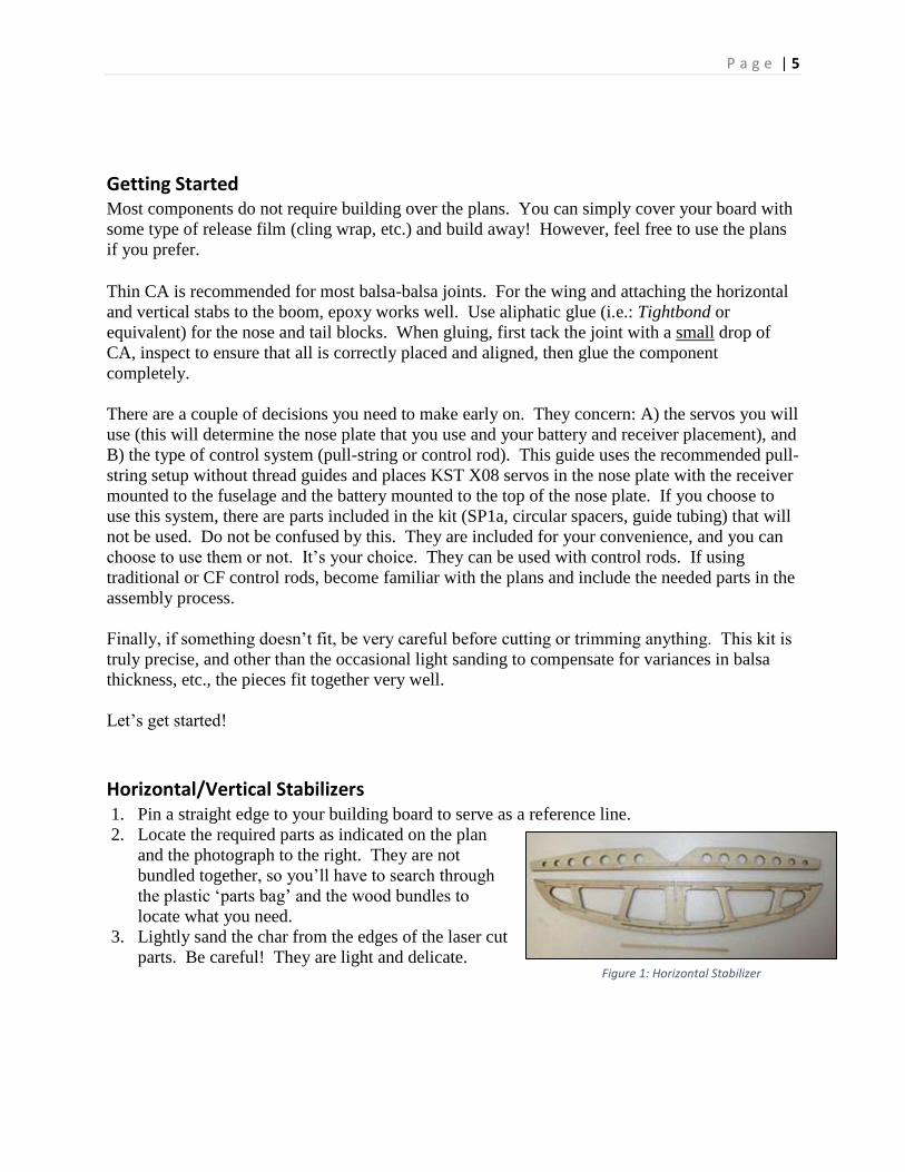
14. Begin with one of the sanded shorter
pine stringers. Insert it from the rear of
the fuselage (SP5) into the notch just
above the sheer webbing/decking. Push
it completely into the fuselage until it is
flush with SP5. The forward end will
be at the surface or perhaps a millimeter
or two beyond SP2. The stringers fit
well against the fuselage sides, so thin
or medium CA run down the stringer
between it and the fuse works well. Figure 6: Stick Locations on SP2
P a g e | 9
Some modelers add a medium CA fillet at the points where the stringers pass through the
plywood formers as reinforcement for the joint.
15. Repeat with the second short pine stick for the other side.
16. Install the T-nut in the wing hold down.
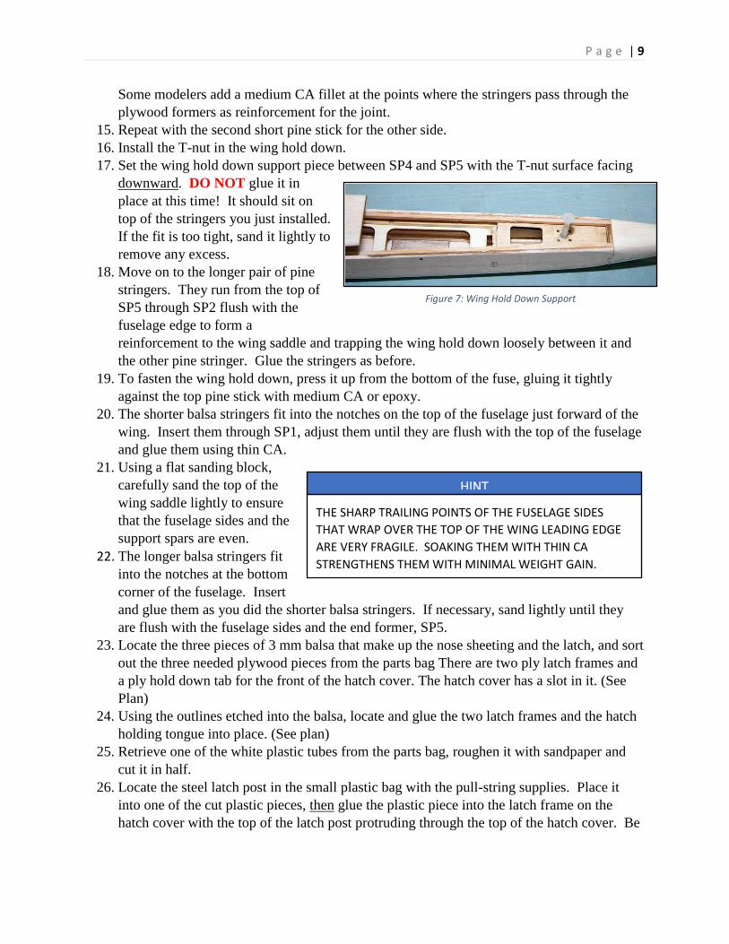
17. Set the wing hold down support piece between SP4 and SP5 with the T-nut surface facing
downward. DO NOT glue it in
place at this time! It should sit on
top of the stringers you just installed.
If the fit is too tight, sand it lightly to
remove any excess.
18. Move on to the longer pair of pine
stringers. They run from the top of
SP5 through SP2 flush with the
fuselage edge to form a
reinforcement to the wing saddle and trapping the wing hold down loosely between it and
the other pine stringer. Glue the stringers as before.
19. To fasten the wing hold down, press it up from the bottom of the fuse, gluing it tightly
against the top pine stick with medium CA or epoxy.
20. The shorter balsa stringers fit into the notches on the top of the fuselage just forward of the
wing. Insert them through SP1, adjust them until they are flush with the top of the fuselage
and glue them using thin CA.
21. Using a flat sanding block,
carefully sand the top of the
wing saddle lightly to ensure
that the fuselage sides and the
support spars are even.
22. The longer balsa stringers fit
into the notches at the bottom
corner of the fuselage. Insert
and glue them as you did the shorter balsa stringers. If necessary, sand lightly until they
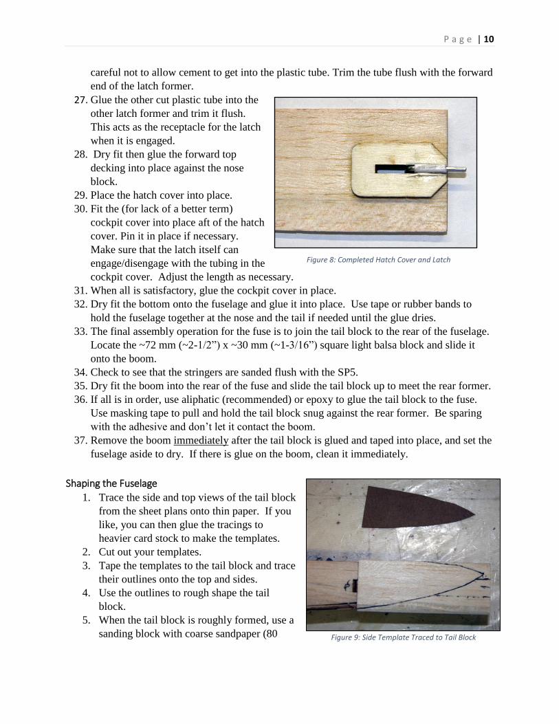
are flush with the fuselage sides and the end former, SP5. 23. Locate the three pieces of 3 mm balsa that make up the nose sheeting and the latch, and sort
out the three needed plywood pieces from the parts bag There are two ply latch frames and
a ply hold down tab for the front of the hatch cover. The hatch cover has a slot in it. (See
Plan)
24. Using the outlines etched into the balsa, locate and glue the two latch frames and the hatch
holding tongue into place. (See plan)
25. Retrieve one of the white plastic tubes from the parts bag, roughen it with sandpaper and
cut it in half.
26. Locate the steel latch post in the small plastic bag with the pull-string supplies. Place it
into one of the cut plastic pieces, then glue the plastic piece into the latch frame on the
hatch cover with the top of the latch post protruding through the top of the hatch cover. Be
HINT
THE SHARP TRAILING POINTS OF THE FUSELAGE SIDES
THAT WRAP OVER THE TOP OF THE WING LEADING EDGE
ARE VERY FRAGILE. SOAKING THEM WITH THIN CA
STRENGTHENS THEM WITH MINIMAL WEIGHT GAIN.
Figure 7: Wing Hold Down Support
P a g e | 10
careful not to allow cement to get into the plastic tube. Trim the tube flush with the forward
end of the latch former.
27. Glue the other cut plastic tube into the
other latch former and trim it flush.
This acts as the receptacle for the latch
when it is engaged. 28. Dry fit then glue the forward top
decking into place against the nose
block.
29. Place the hatch cover into place.
30. Fit the (for lack of a better term)
cockpit cover into place aft of the hatch
cover. Pin it in place if necessary.
Make sure that the latch itself can
engage/disengage with the tubing in the
cockpit cover. Adjust the length as necessary.
31. When all is satisfactory, glue the cockpit cover in place.
32. Dry fit the bottom onto the fuselage and glue it into place. Use tape or rubber bands to
hold the fuselage together at the nose and the tail if needed until the glue dries.
33. The final assembly operation for the fuse is to join the tail block to the rear of the fuselage.
Locate the ~72 mm (~2-1/2”) x ~30 mm (~1-3/16”) square light balsa block and slide it
onto the boom.
34. Check to see that the stringers are sanded flush with the SP5.
35. Dry fit the boom into the rear of the fuse and slide the tail block up to meet the rear former.
36. If all is in order, use aliphatic (recommended) or epoxy to glue the tail block to the fuse.
Use masking tape to pull and hold the tail block snug against the rear former. Be sparing
with the adhesive and don’t let it contact the boom.
37. Remove the boom immediately after the tail block is glued and taped into place, and set the
fuselage aside to dry. If there is glue on the boom, clean it immediately.
Shaping the Fuselage
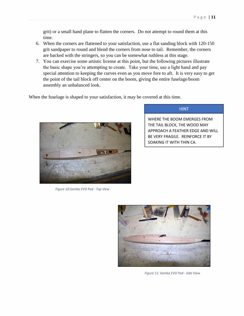
1. Trace the side and top views of the tail block
from the sheet plans onto thin paper. If you
like, you can then glue the tracings to
heavier card stock to make the templates.
2. Cut out your templates.
3. Tape the templates to the tail block and trace
their outlines onto the top and sides.
4. Use the outlines to rough shape the tail
block.
5. When the tail block is roughly formed, use a
sanding block with coarse sandpaper (80 Figure 9: Side Template Traced to Tail Block
Figure 8: Completed Hatch Cover and Latch
P a g e | 11
grit) or a small hand plane to flatten the corners. Do not attempt to round them at this
time.
6. When the corners are flattened to your satisfaction, use a flat sanding block with 120-150
grit sandpaper to round and blend the corners from nose to tail. Remember, the corners
are backed with the stringers, so you can be somewhat ruthless at this stage.
7. You can exercise some artistic license at this point, but the following pictures illustrate
the basic shape you’re attempting to create. Take your time, use a light hand and pay
special attention to keeping the curves even as you move fore to aft. It is very easy to get
the point of the tail block off center on the boom, giving the entire fuselage/boom
assembly an unbalanced look.
When the fuselage is shaped to your satisfaction, it may be covered at this time.
Figure 10:Samba EVO Pod - Top View
HINT
WHERE THE BOOM EMERGES FROM
THE TAIL BLOCK, THE WOOD MAY
APPROACH A FEATHER EDGE AND WILL
BE VERY FRAGILE. REINFORCE IT BY
SOAKING IT WITH THIN CA.
Figure 11: Samba EVO Pod - Side View
P a g e | 12
Wing Center Section This part of the build goes quickly, particularly if you’re using CA. It
can be divided into three main phases:
1. Wing preparation where you sort out all the bits and pieces,
glue the longer parts together (top sheeting, spar, trailing
edge), and lay out the basic center section outline.
2. Building up the wing itself.
3. Applying top sheeting, building and installing the spoiler,
sanding, etc.
Wing Preparation
1. Pin down a straight edge to build against. Your wing build accuracy starts here!
2. If building over the plans, cover the center section with a non-stick covering: wax paper,
cling wrap, etc.
3. Locate the following:
a. Top sheeting (2 pcs.)
b. Bottom sheeting (3 pcs)
c. Spar sheer web (2 pcs)
d. Trailing edge (2 pcs)
Figure 12: Wing Center Section Parts
4. Lay out the top sheeting pieces with the
long leading edge against the straight
edge. (See Fig. 13)
5. Pin securely, weigh it down, then glue.
6. When dry, carefully remove the sheet
from the building board taking care to
not stress the glue joint. The balsa is
light and cannot take much pressure.
7. Use a flat sanding block to sand the glue joints to
remove any excess glue. It is much easier to do this now than after they are installed.
HINT
BUSINESSES THAT SELL
GRANITE COUNTER TOPS
ARE EXCELLENT SOURCES OF
SMALL STONE BLOCKS
SUITABLE FOR WEIGHTS!
Figure 13: Wing Center Section Glued
P a g e | 13
8. Join the bottom sheeting, spar, and trailing edge using the same technique as above.
9. When the longer parts are complete, pin the trailing edge as accurately as you can over
the plans. Note: Building over the plans is not strictly necessary. If you are building
over the plans, trust the components. The parts are correct!
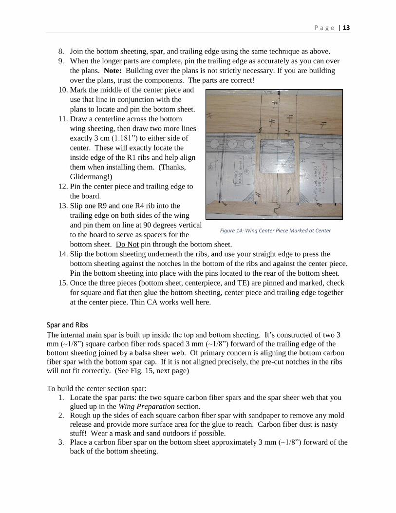
10. Mark the middle of the center piece and
use that line in conjunction with the
plans to locate and pin the bottom sheet.
11. Draw a centerline across the bottom
wing sheeting, then draw two more lines
exactly 3 cm (1.181”) to either side of
center. These will exactly locate the
inside edge of the R1 ribs and help align
them when installing them. (Thanks,
Glidermang!)
12. Pin the center piece and trailing edge to
the board.
13. Slip one R9 and one R4 rib into the
trailing edge on both sides of the wing
and pin them on line at 90 degrees vertical
to the board to serve as spacers for the
bottom sheet. Do Not pin through the bottom sheet.
14. Slip the bottom sheeting underneath the ribs, and use your straight edge to press the
bottom sheeting against the notches in the bottom of the ribs and against the center piece.
Pin the bottom sheeting into place with the pins located to the rear of the bottom sheet.
15. Once the three pieces (bottom sheet, centerpiece, and TE) are pinned and marked, check
for square and flat then glue the bottom sheeting, center piece and trailing edge together
at the center piece. Thin CA works well here.
Spar and Ribs
The internal main spar is built up inside the top and bottom sheeting. It’s constructed of two 3
mm (~1/8”) square carbon fiber rods spaced 3 mm (~1/8”) forward of the trailing edge of the
bottom sheeting joined by a balsa sheer web. Of primary concern is aligning the bottom carbon
fiber spar with the bottom spar cap. If it is not aligned precisely, the pre-cut notches in the ribs
will not fit correctly. (See Fig. 15, next page)
To build the center section spar:
1. Locate the spar parts: the two square carbon fiber spars and the spar sheer web that you
glued up in the Wing Preparation section.
2. Rough up the sides of each square carbon fiber spar with sandpaper to remove any mold
release and provide more surface area for the glue to reach. Carbon fiber dust is nasty
stuff! Wear a mask and sand outdoors if possible.
3. Place a carbon fiber spar on the bottom sheet approximately 3 mm (~1/8”) forward of the
back of the bottom sheeting.
Figure 14: Wing Center Piece Marked at Center

P a g e | 14
4. Fit ribs R1, R3, the middle R4, and R9 in place on both sides of the centerline, trapping
the carbon fiber in the notches pre-cut into the ribs and aligning it with the bottom sheet.
5. Pin the spar and the ribs securely in
place.
6. Lightly tack glue the carbon fiber
spar in place and remove the ribs.
7. Finish gluing down the carbon fiber
spar. Press down on the carbon fiber
to ensure a good bond. Use thin CA
for this. Medium CA will have
difficulty working underneath the
spar and might leave a fillet that
would prevent the balsa sheer web
from mating correctly with the carbon fiber.
8. Dry fit the balsa sheer web against the carbon
fiber spar with the notches upward.
9. When satisfied with the fit, glue the sheer web to
the forward side of the carbon spar using medium
CA. Pin/brace the spar perpendicular to and firmly
against the bottom sheeting.
10. Place the right R1 into place and pin it securely.
NOTE: Do Not forget to very lightly sand the
charring from the plywood ribs to give a better
glue bond. Use medium CA or epoxy.
11. Insert the provided plywood sheeting supports
under the leading edge of the bottom sheet
to press the sheet into contact with the
leading edge of R1.
12. Glue R1 into place using aliphatic or
medium CA. NOTE: Remove any glue
that squeezes out on the bottom inside of
R1. The fillet will prevent the hatch
frame from seating completely. A slight
fillet on the outside is permissible.
13. Check to see that R1 is at a right angle to
the bottom sheet then weigh it down.
14. Locate the 3 mm (~1/8”) plywood hatch
frame and dry fit it into the right hand R1.
Be certain that it fits tightly against the rib.
15. Use aliphatic or medium CA to glue the hatch frame to the bottom sheeting and R1.
16. Repeat Steps #10 -- #12 for the left hand R1.
17. Locate the 4 mm (~3/16”) ply half rib, its mounting plate (See plans), and the two 10 mm
(~3/8”) x 10 mm x ~38 mm (~1.5”) balsa blocks that serve as reinforcements and spacers
Figure 15: Ribs Used to Place Bottom Spar
Figure 16: Spar Webbing and Bottom Spar Weighted
Figure 17: Plywood Bottom Sheeting Supports

P a g e | 15
for the carbon fiber wing hold down pin at the leading edge. NOTE: Remove any char
from the plywood pieces.
18. Dry fit the plywood spar rib
reinforcement between the two R1 ribs
in front of the spar. Sand if necessary.
19. Glue the spar mounting plate into place
with aliphatic or medium CA.
20. Glue the half rib into place. (See plans)
Ensure that it is in good contact against
the spar web and bottom sheeting all
along its bottom length.
21. Dry fit and glue the two balsa spacer blocks into place. When dry, sand to match rib
contour.
22. Fit and pin all the ribs securely into the center section,
ensuring that all but the R9 ribs are at 90° to the
board. IMPORTANT! The R9 ribs are not at 90° to
the board, but are slanted slightly inward as part of
the first polyhedral break angle! (See Fig. 19)
23. Use thin CA to glue the ribs into the trailing edge and
lightly tack glue the ribs at the rear of the bottom
sheeting only. Use the sheeting supports to help pull
the bottom sheeting against the rib bottoms.
WARNING!
THE MOST COMMON CAUSE OF A WARPED WING IS A FAILURE TO FULLY SEAT THE RIBS AT EVERY
POINT OF CONTACT. DOUBLE CHECK FOR THIS!
Figure 20: Using Bottom Sheeting Supports
Figure 18: Hatch Frame and Wing Hold Down
Figure 19: Tilted R9
P a g e | 16
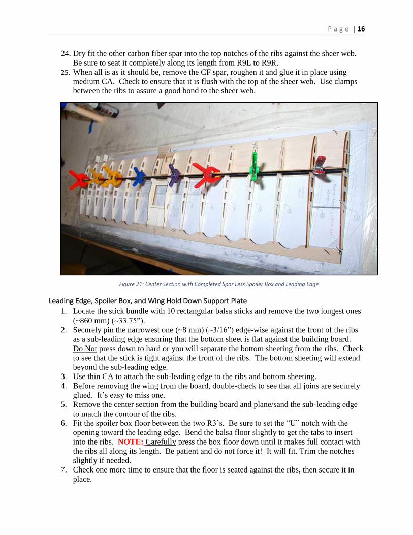
24. Dry fit the other carbon fiber spar into the top notches of the ribs against the sheer web.
Be sure to seat it completely along its length from R9L to R9R.
25. When all is as it should be, remove the CF spar, roughen it and glue it in place using
medium CA. Check to ensure that it is flush with the top of the sheer web. Use clamps
between the ribs to assure a good bond to the sheer web.
Leading Edge, Spoiler Box, and Wing Hold Down Support Plate
1. Locate the stick bundle with 10 rectangular balsa sticks and remove the two longest ones
(~860 mm) (~33.75”).
2. Securely pin the narrowest one (~8 mm) (~3/16”) edge-wise against the front of the ribs
as a sub-leading edge ensuring that the bottom sheet is flat against the building board.
Do Not press down to hard or you will separate the bottom sheeting from the ribs. Check
to see that the stick is tight against the front of the ribs. The bottom sheeting will extend
beyond the sub-leading edge.
3. Use thin CA to attach the sub-leading edge to the ribs and bottom sheeting.
4. Before removing the wing from the board, double-check to see that all joins are securely
glued. It’s easy to miss one.
5. Remove the center section from the building board and plane/sand the sub-leading edge
to match the contour of the ribs.
6. Fit the spoiler box floor between the two R3’s. Be sure to set the “U” notch with the
opening toward the leading edge. Bend the balsa floor slightly to get the tabs to insert
into the ribs. NOTE: Carefully press the box floor down until it makes full contact with
the ribs all along its length. Be patient and do not force it! It will fit. Trim the notches
slightly if needed.
7. Check one more time to ensure that the floor is seated against the ribs, then secure it in
place.
Figure 21: Center Section with Completed Spar Less Spoiler Box and Leading Edge

P a g e | 17
8. Roughen the outside of the two pieces of 5 mm
aluminum tubing that serve as wing joiner
bushings. Trial fit them through R9 and into R8
for each end of the center section, then use either
epoxy or medium CA to secure them in place.
Pay attention to not allow any adhesive into the
tubes and make sure that you get the outside
ends flush with R9.
9. Locate four of the thin triangular pieces (see Fig.
23). They are braces for the joiner tubes. Glue
one on top of the tube and one on the bottom,
against the tube.
Wing Hold Down Support & Top Sheeting
1. Now dig out two of the four pieces of 2 mm (~1/16”) x ~57 mm (~2-1/4”) pieces of
carbon fiber rod and use medium CA to install them in
the rear of R9 – R8. (See plans)
2. Locate the 60 mm (~2-3/8”) piece of trailing edge
stock and the matching piece of 3 mm (~1/8”) ply
with the hole in it. These will become your wing hold
down block. Glue the triangle stock against the
trailing edge making certain that it is pressed solidly
against the bottom center piece.
3. Use medium CA or aliphatic glue to glue the plywood
piece in place. Weigh it down as it dries.
4. Install the four triangular gussets outboard of the R1
ribs and inboard of the R9’s, as shown on the plans.
5. Inspect one last time to see that all parts have been
installed and are securely glued.
Figure 22: Joiner Tube and CF Reinforcement
Figure 23: Joiner Tube Braces
Figure 24: Wing Hold-Down Parts w/o Spoiler Box
P a g e | 18
6. The next step will be to install the top sheeting. Pin the trailing edge to the building board
and pin the ribs aft of the spar. This helps to guarantee a warp free wing.
7. Dry fit the top sheeting to the center section. It is helpful to moisten the sheeting to allow
it to bend.
8. Finally, glue the top sheeting. The choice of adhesive is up to you. Some prefer CA for
the speed, others aliphatic, and still others use epoxy or a combination of all three.
NOTE: When gluing the sheeting, pay attention that
the sheeting contacts the sub-leading edge all along
the join! Use clamps, pins and weights where
needed.
9. Fit and install the top spoiler cover between the top
sheeting and the trailing edge.
10. When dry, carefully remove the cross pieces from
the spoiler opening to open it up, then plane/sand the
forward edge of the sheeting and sub-leading edge
completely flat.
11. Glue the leading edge to the sub-leading ledge. Use an adhesive that sands easily.
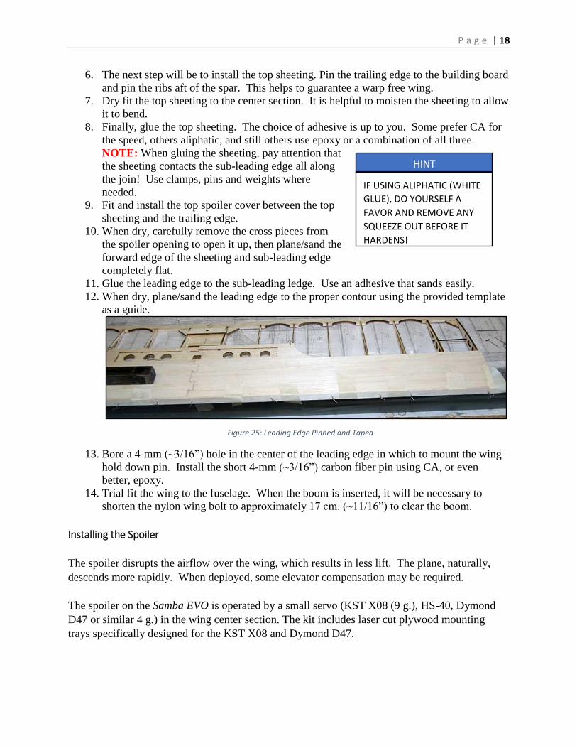
12. When dry, plane/sand the leading edge to the proper contour using the provided template
as a guide.
13. Bore a 4-mm (~3/16”) hole in the center of the leading edge in which to mount the wing
hold down pin. Install the short 4-mm (~3/16”) carbon fiber pin using CA, or even
better, epoxy.
14. Trial fit the wing to the fuselage. When the boom is inserted, it will be necessary to
shorten the nylon wing bolt to approximately 17 cm. (~11/16”) to clear the boom.
Installing the Spoiler
The spoiler disrupts the airflow over the wing, which results in less lift. The plane, naturally,
descends more rapidly. When deployed, some elevator compensation may be required.
The spoiler on the Samba EVO is operated by a small servo (KST X08 (9 g.), HS-40, Dymond
D47 or similar 4 g.) in the wing center section. The kit includes laser cut plywood mounting
trays specifically designed for the KST X08 and Dymond D47.
HINT
IF USING ALIPHATIC (WHITE
GLUE), DO YOURSELF A
FAVOR AND REMOVE ANY
SQUEEZE OUT BEFORE IT
HARDENS!
Figure 25: Leading Edge Pinned and Taped

P a g e | 19
Mounting the spoiler servo is a builder option, but many choose to glue the mounting frame into
the servo bay then use thin double-side tape to mount the servo to the balsa. Hot glue or any
other builder preferred method will work as well.
An excellent video showing the linkage and operation of the spoiler is available on YouTube at:
Samba EVO Spoiler. Take time to view the video. Pay special attention to the orientation and
placement of the servo, the length of the servo arm and the holes used in the servo arm and the
control horn. Your experience may vary.
To install the spoiler:
1. Trial fit the spoiler into the spoiler box to check the fit, and if using one of the supplied
servo mounts, check to see that your servo fits in the mount.
2. Invert the center section, and place the servo into the
servo well. The end of the servo with the arm will be
under the servo opening, or close to it. With the center
section upside down, the servo will rotate toward the
table when activated.
3. The servo does not operate from the standard center
position. Instead, it rests against one travel limit. Use
a servo tester to set the servo at one limit so that when
activated the servo will rotate the arm upward through
the opening in the spoiler box. Most computer radios
will allow you to limit travel when configuring the
model for operation if the servo raises the spoiler past
90°.
4. Return the servo to what will be the ‘closed’ position and attach a servo arm as close to
horizontal as possible, with the end of the arm pointing forward under the spoiler. The
actual location forward/aft will be determined by the length of your servo arm, your servo
dimensions, etc.
5. If using a servo mounting tray, press the servo into the tray, position it in the desired
location, and mark the location of the servo tray. Do Not place the servo so far forward
that the arm contacts the leading edge of the spoiler box when it is raised.
6. Glue the servo tray into its place and refit the servo. Do Not fasten the servo into
position at this time.
7. Using a servo tester, activate the servo to check its motion. NOTE: The servo must be
free to rotate far enough to raise the spoiler to a desired angle of 90 degrees. For this to
happen, you may have to cut a small notch in the servo box bottom so that the arm will
not contact the box when fully raised.
8. Temporarily hinge the spoiler into the spoiler box, turn the center section over, and using
the servo arm mark the location for the spoiler control horn just to one side of the spoiler
arm. It should be near the spoiler centerline. The control horn has three holes and is in
the sheet of 1.5 mm (~1/16”) ply that held the polyhedral braces.
WARNING
SPOILER SERVO PLACEMENT
IS CRITICAL TO THE PROPER
OPERATION OF THE
SPOILER. TAKE YOUR TIME.
TRIAL FIT AND TEST
EVERYTHING BEFORE
MAKING THE INSTALLATION
PERMANENT.
P a g e | 20
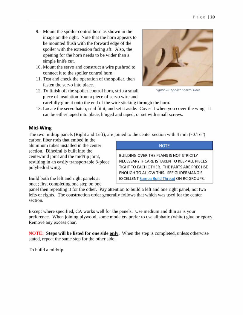
9. Mount the spoiler control horn as shown in the
image on the right. Note that the horn appears to
be mounted flush with the forward edge of the
spoiler with the extension facing aft. Also, the
opening for the horn needs to be wider than a
simple knife cut.
10. Mount the servo and construct a wire pushrod to
connect it to the spoiler control horn.
11. Test and check the operation of the spoiler, then
fasten the servo into place.
12. To finish off the spoiler control horn, strip a small
piece of insulation from a piece of servo wire and
carefully glue it onto the end of the wire sticking through the horn.
13. Locate the servo hatch, trial fit it, and set it aside. Cover it when you cover the wing. It
can be either taped into place, hinged and taped, or set with small screws.
Mid-Wing The two mid/tip panels (Right and Left), are joined to the center section with 4 mm (~3/16”)
carbon fiber rods that embed in the
aluminum tubes installed in the center
section. Dihedral is built into the
center/mid joint and the mid/tip joint,
resulting in an easily transportable 3-piece
polyhedral wing.
Build both the left and right panels at
once; first completing one step on one
panel then repeating it for the other. Pay attention to build a left and one right panel, not two
lefts or rights. The construction order generally follows that which was used for the center
section.
Except where specified, CA works well for the panels. Use medium and thin as is your
preference. When joining plywood, some modelers prefer to use aliphatic (white) glue or epoxy.
Remove any excess char.
NOTE: Steps will be listed for one side only. When the step is completed, unless otherwise
stated, repeat the same step for the other side.
To build a mid/tip:
NOTE
BUILDING OVER THE PLANS IS NOT STRICTLY
NECESSARY IF CARE IS TAKEN TO KEEP ALL PIECES
TIGHT TO EACH OTHER. THE PARTS ARE PREC1ISE
ENOUGH TO ALLOW THIS. SEE GLIDERMANG’S
EXCELLENT Samba Build Thread ON RC GROUPS.
Figure 26: Spoiler Control Horn
P a g e | 21
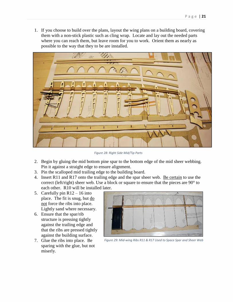
1. If you choose to build over the plans, layout the wing plans on a building board, covering
them with a non-stick plastic such as cling wrap. Locate and lay out the needed parts
where you can reach them, but leave room for you to work. Orient them as nearly as
possible to the way that they to be are installed.
2. Begin by gluing the mid bottom pine spar to the bottom edge of the mid sheer webbing.
Pin it against a straight edge to ensure alignment.
3. Pin the scalloped mid trailing edge to the building board.
4. Insert R11 and R17 onto the trailing edge and the spar sheer web. Be certain to use the
correct (left/right) sheer web. Use a block or square to ensure that the pieces are 90° to
each other. R10 will be installed later.
5. Carefully pin R12 – 16 into
place. The fit is snug, but do
not force the ribs into place.
Lightly sand where necessary.
6. Ensure that the spar/rib
structure is pressing tightly
against the trailing edge and
that the ribs are pressed tightly
against the building surface.
7. Glue the ribs into place. Be
sparing with the glue, but not
miserly.
Figure 28: Right Side Mid/Tip Parts
Figure 29: Mid-wing Ribs R11 & R17 Used to Space Spar and Sheer Web
P a g e | 22
8. Now attach the lower wing
sheet/strip to the forward rib
bottoms. These are the ~400 mm
(~15-3/4”) x ~15 mm (~9/16”)
pieces of slightly curved ~2 mm
(~1/16”) balsa. NOTE: Like the
sheer webs, these are matched to
Left and Right. When in place, the
etching for the rib placement is
visible and the side with the slightly
greater curve is to the outboard end
of the wing. Use the “lifter wedges” that you used to lift the center section bottom
sheeting into place.
9. With the wedges in place to pull the bottom sheeting against the ribs, press lightly down
on the rib to ensure proper alignment and contact with the edge, and use thin CA to bond.
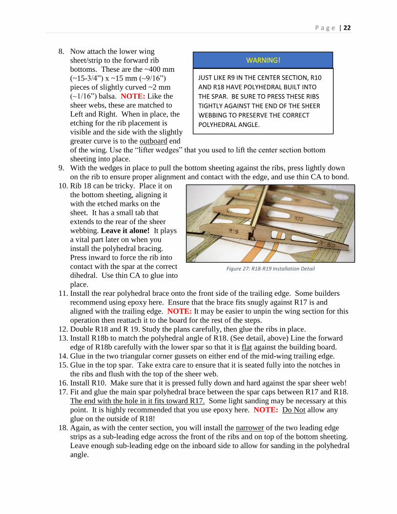
10. Rib 18 can be tricky. Place it on
the bottom sheeting, aligning it
with the etched marks on the
sheet. It has a small tab that
extends to the rear of the sheer
webbing. Leave it alone! It plays
a vital part later on when you
install the polyhedral bracing.
Press inward to force the rib into
contact with the spar at the correct
dihedral. Use thin CA to glue into
place.
11. Install the rear polyhedral brace onto the front side of the trailing edge. Some builders
recommend using epoxy here. Ensure that the brace fits snugly against R17 is and
aligned with the trailing edge. NOTE: It may be easier to unpin the wing section for this
operation then reattach it to the board for the rest of the steps.
12. Double R18 and R 19. Study the plans carefully, then glue the ribs in place.
13. Install R18b to match the polyhedral angle of R18. (See detail, above) Line the forward
edge of R18b carefully with the lower spar so that it is flat against the building board.
14. Glue in the two triangular corner gussets on either end of the mid-wing trailing edge.
15. Glue in the top spar. Take extra care to ensure that it is seated fully into the notches in
the ribs and flush with the top of the sheer web.
16. Install R10. Make sure that it is pressed fully down and hard against the spar sheer web!
17. Fit and glue the main spar polyhedral brace between the spar caps between R17 and R18.
The end with the hole in it fits toward R17. Some light sanding may be necessary at this
point. It is highly recommended that you use epoxy here. NOTE: Do Not allow any
glue on the outside of R18!
18. Again, as with the center section, you will install the narrower of the two leading edge
strips as a sub-leading edge across the front of the ribs and on top of the bottom sheeting.
Leave enough sub-leading edge on the inboard side to allow for sanding in the polyhedral
angle.
WARNING!
JUST LIKE R9 IN THE CENTER SECTION, R10
AND R18 HAVE POLYHEDRAL BUILT INTO
THE SPAR. BE SURE TO PRESS THESE RIBS
TIGHTLY AGAINST THE END OF THE SHEER
WEBBING TO PRESERVE THE CORRECT
POLYHEDRAL ANGLE.
Figure 27: R18-R19 Installation Detail

P a g e | 23
19. Trim the sub-leading-edge close to length and plane/sand a bevel it to match the rib
profile leaving the front flat.
20. Glue on the top sheeting. Align it to the end of R10. Pin it and weigh it down to ensure
good contact. NOTE: The sheeting is cut to form! It fits the curve of the sub-leading
edge. If the curves do not match closely, try the other piece of sheeting.
21. When dry, plane/sand the sub-leading edge flat and perpendicular.
22. Pin and glue the wider piece of leading edge to the sub-leading edge and sheeting.
23. When dry, use the edge profile guide to sand the leading-edge profile.
24. Bevel one end of one of the 4 mm carbon fiber
rods to match the angle at which it meets the
sheer web. Lightly sand the beveled half to
roughen the surface. Chamfer/round the other
end.
25. Insert the rod into the mid-wing section with the
beveled side flat against the sheer webbing, then
dry fit the mid-wing to the center section.
26. Remove the mid-wing, and use either medium
CA or epoxy to glue the CF rod into the mid-
wing with the flat bevel against the mid-section
sheer web. NOTE: Ensure that no adhesive builds up
beyond the top or bottom of the rod.
27. As with the center section, use two of the thin triangular wedges (Fig. 24) to support the
carbon fiber rod. Glue one on top and one on the bottom of the rod.
28. Locate one of the 4 mm (~5/32”) wooden locating pins, chamfer one end and glue the
non-chamfered end into the aft 4 mm hole in the mid-wing using medium CA or epoxy.
29. Use medium CA to install the 2-mm carbon fiber rod brace just forward of the locating
pin.
30. Trim and sand the spars and sheeting flush against the end ribs on both ends. Check to
see that there is no squeeze-out around the CF rods.
If you were not building the left and right sections concurrently, return to Step #1, Page 21, and
repeat.
Wing Tip
The wing tip and its associated winglet are the last major assembly modules for the Samba, yet
they are among the most critical parts that you will build. The tips have been especially designed
to reduce vortex drag at the end of the wing, and care needs to be exercised in their construction.
To build the wing tip section (R20 – R22):
1. Locate all the tip parts: Pine spar sticks (~163 mm (~6-7/16”) long), sheer webbing, R20-
22, 2 pcs. of leading edge, trailing edge piece, and 2 triangular gussets for each tip.
2. Glue the bottom pine spar even with the bottom of the sheer webbing.
3. As you did with the other wing sections, pin the tip trailing edge to the board and use
R20, R21 and R22 to trap the bottom tip spar and the tip sheer web into place. NOTE:
The slightly wider end of the sheer web fits to the inboard side (R19) of each tip.
Figure 28: Beveled Carbon Fiber Rod
P a g e | 24
4. Check to see that all is aligned properly, then use thin CA to glue the parts together.
5. Add the upper spar, check to see that it is fully seated into the rib notches and flush with
the sheer webbing, then glue.
6. Place and pin the bottom sheeting into place using the wedges to pull it up against the
ribs as before.
7. As with the center section and mid-wing, install the sub-leading edge.
8. Shape the sub-leading edge to the rib profile.
9. Install and trim top sheeting.
10. Install the leading-edge.
11. Shape the leading-edge profile.
12. Add the tip outboard triangular gusset at R22.
13. Sand spars, webbing, and sheeting on the ends of the tip flush with the existing ribs.
Repeat for the other wing tip if not building the two concurrently.
Attaching the Tip to the Mid-wing
1. Pin the mid-section securely to the building board.
2. Trial fit the mid-wing and the tip together. Sand the polyhedral braces as needed to fit
between the pine spar caps.
3. Make any adjustments needed to fit R19 tightly against R18 and the two pieces of trailing
edge together without gaps.
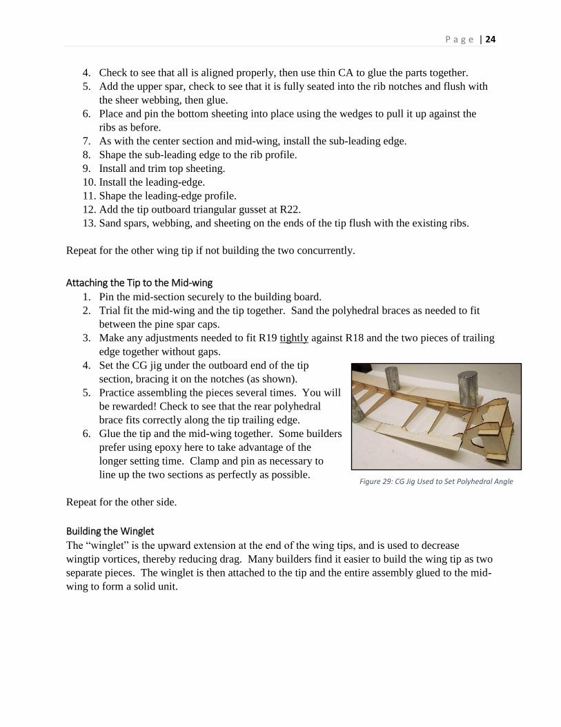
4. Set the CG jig under the outboard end of the tip
section, bracing it on the notches (as shown).
5. Practice assembling the pieces several times. You will
be rewarded! Check to see that the rear polyhedral
brace fits correctly along the tip trailing edge.
6. Glue the tip and the mid-wing together. Some builders
prefer using epoxy here to take advantage of the
longer setting time. Clamp and pin as necessary to
line up the two sections as perfectly as possible.
Repeat for the other side.
Building the Winglet
The “winglet” is the upward extension at the end of the wing tips, and is used to decrease
wingtip vortices, thereby reducing drag. Many builders find it easier to build the wing tip as two
separate pieces. The winglet is then attached to the tip and the entire assembly glued to the mid-
wing to form a solid unit.
Figure 29: CG Jig Used to Set Polyhedral Angle
P a g e | 25
To build the winglet:
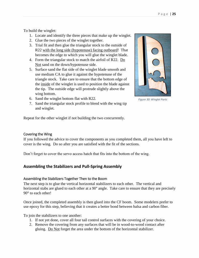
1. Locate and identify the three pieces that make up the winglet.
2. Glue the two pieces of the winglet together.
3. Trial fit and then glue the triangular stock to the outside of
R22 with the long side (hypotenuse) facing outboard! That
becomes the edge to which you will glue the winglet blade.
4. Form the triangular stock to match the airfoil of R22. Do
Not sand on the down/hypotenuse side.
5. Surface sand the flat side of the winglet blade smooth and
use medium CA to glue it against the hypotenuse of the
triangle stock. Take care to ensure that the bottom edge of
the inside of the winglet is used to position the blade against
the tip. The outside edge will protrude slightly above the
wing bottom.
6. Sand the winglet bottom flat with R22.
7. Sand the triangular stock profile to blend with the wing tip
and winglet.
Repeat for the other winglet if not building the two concurrently.
Covering the Wing
If you followed the advice to cover the components as you completed them, all you have left to
cover is the wing. Do so after you are satisfied with the fit of the sections.
Don’t forget to cover the servo access hatch that fits into the bottom of the wing.
Assembling the Stabilizers and Pull-Spring Assembly
Assembling the Stabilizers Together Then to the Boom
The next step is to glue the vertical horizontal stabilizers to each other. The vertical and
horizontal stabs are glued to each other at a 90° angle. Take care to ensure that they are precisely
90° to each other!
Once joined, the completed assembly is then glued into the CF boom. Some modelers prefer to
use epoxy for this step, believing that it creates a better bond between balsa and carbon fiber.
To join the stabilizers to one another:
1. If not yet done, cover all four tail control surfaces with the covering of your choice.
2. Remove the covering from any surfaces that will be in wood-to-wood contact after
gluing. Do Not forget the area under the bottom of the horizontal stabilizer.
Figure 30: Winglet Parts

P a g e | 26
3. Trial fit the two stab parts together. NOTE: It is vital that the two stabilizers are at 90°
to each other in both the vertical and horizontal dimensions!
4. Alignment horizontally (fore/aft) is achieved by carefully aligning the bottom edge of the
horizontal stab with the bottom edge of the cut for the boom in the vertical stab.
5. Dry fit the parts together and check to see that they are square in both the horizontal and
vertical dimensions…then check it again!
6. Remove the parts from the jig and glue them together. Again, many modelers use epoxy
here to take advantage of the increased setting time.
7. Place everything back in the jig and check for square. Use weights, tape, pins,
string…whatever it takes…to ensure that they are aligned as perfectly as possible.
To attach the stabilizers to the boom:
Trial fit the assembly to the boom, and mark the contact points between the boom and the stab
assembly with a felt tip marker. NOTE: Ensure that
the vertical stab tracks a straight line down the center
of the boom!
1. Use 150-220 grit sand paper to roughen the
surface of the CF boom where the stab
assembly will contact it.
2. Use epoxy to attach the stab assembly to the
boom.
Attaching the Fuselage and Boom
The most critical part of this operation is to ensure that the flat across the wing saddle is perfectly
parallel to the horizontal stabilizer. How you ensure that the fuse and horizontal stab are parallel
is up to you. Methods range from using a digital inclinometer, a level, or even the Mk. I
Calibrated Eyeball.
To attach the fuselage to the boom assembly:
1. If not done, cover the fuselage.
2. Trial fit the fuse and boom assembly.
3. Set the fuselage and horizontal stab parallel to
each other, then trace the rear outline of the
fuse where the boom emerges being careful
not to move anything.
4. Separate the fuselage and boom, then roughen
the boom following the outline you just
traced back to where the boom emerges from
the tail block.
5. Glue the fuselage to the boom using the tracing to ensure that the fuse and the horizontal
stab are parallel. Epoxy is recommended for this operation.
6. Allow to cure undisturbed, and you’ll have a completed pod-boom-tail component!
HINT
ONE OF THE MOST USEFUL TOOLS
THAT YOU CAN HAVE ON YOUR BENCE
IS A COMMON EMERY BOARD. THEY
MAKE GREAT SANDING STICKS.
HINT
SEVERAL FREE OR INEXPENSIVE SMART
PHONE INCLINOMETER APPS ARE
AVAILABLE. ONE OF THE MOST
RECOMMENDED IS ‘CLINOMETER’,
AVAILABLE FOR BOTH ANDROID AND
MAC.
P a g e | 27
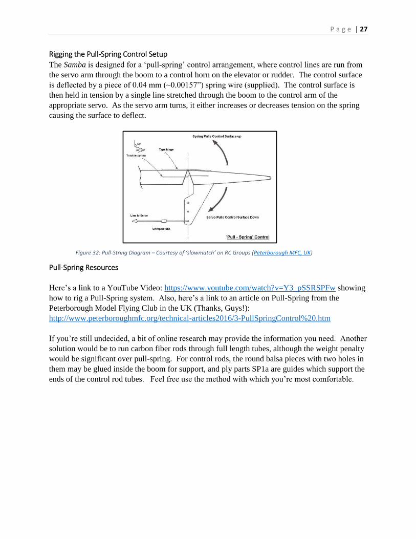
Rigging the Pull-Spring Control Setup
The Samba is designed for a ‘pull-spring’ control arrangement, where control lines are run from
the servo arm through the boom to a control horn on the elevator or rudder. The control surface
is deflected by a piece of 0.04 mm (~0.00157”) spring wire (supplied). The control surface is
then held in tension by a single line stretched through the boom to the control arm of the
appropriate servo. As the servo arm turns, it either increases or decreases tension on the spring
causing the surface to deflect.
Pull-Spring Resources
Here’s a link to a YouTube Video: https://www.youtube.com/watch?v=Y3_pSSRSPFw showing
how to rig a Pull-Spring system. Also, here’s a link to an article on Pull-Spring from the
Peterborough Model Flying Club in the UK (Thanks, Guys!):
http://www.peterboroughmfc.org/technical-articles2016/3-PullSpringControl%20.htm
If you’re still undecided, a bit of online research may provide the information you need. Another
solution would be to run carbon fiber rods through full length tubes, although the weight penalty
would be significant over pull-spring. For control rods, the round balsa pieces with two holes in
them may be glued inside the boom for support, and ply parts SP1a are guides which support the
ends of the control rod tubes. Feel free use the method with which you’re most comfortable.
Figure 32: Pull-String Diagram – Courtesy of ‘slowmatch’ on RC Groups (Peterborough MFC, UK)
P a g e | 28
To build the Pull-Spring Control:
1. Hinge the rudder and elevator using the method of your choice. This manual uses taped
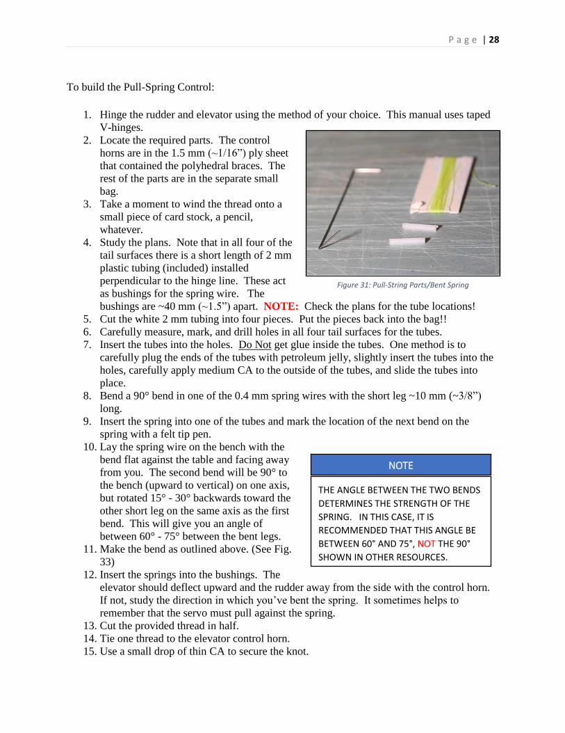
V-hinges. 2. Locate the required parts. The control
horns are in the 1.5 mm (~1/16”) ply sheet
that contained the polyhedral braces. The
rest of the parts are in the separate small
bag. 3. Take a moment to wind the thread onto a
small piece of card stock, a pencil,
whatever. 4. Study the plans. Note that in all four of the
tail surfaces there is a short length of 2 mm
plastic tubing (included) installed
perpendicular to the hinge line. These act
as bushings for the spring wire. The
bushings are ~40 mm (~1.5”) apart. NOTE: Check the plans for the tube locations! 5. Cut the white 2 mm tubing into four pieces. Put the pieces back into the bag!!
6. Carefully measure, mark, and drill holes in all four tail surfaces for the tubes. 7. Insert the tubes into the holes. Do Not get glue inside the tubes. One method is to
carefully plug the ends of the tubes with petroleum jelly, slightly insert the tubes into the
holes, carefully apply medium CA to the outside of the tubes, and slide the tubes into
place. 8. Bend a 90° bend in one of the 0.4 mm spring wires with the short leg ~10 mm (~3/8”)
long.
9. Insert the spring into one of the tubes and mark the location of the next bend on the
spring with a felt tip pen.
10. Lay the spring wire on the bench with the
bend flat against the table and facing away
from you. The second bend will be 90° to
the bench (upward to vertical) on one axis,
but rotated 15° - 30° backwards toward the
other short leg on the same axis as the first
bend. This will give you an angle of
between 60° - 75° between the bent legs. 11. Make the bend as outlined above. (See Fig.
33) 12. Insert the springs into the bushings. The
elevator should deflect upward and the rudder away from the side with the control horn.
If not, study the direction in which you’ve bent the spring. It sometimes helps to
remember that the servo must pull against the spring.
13. Cut the provided thread in half. 14. Tie one thread to the elevator control horn.
15. Use a small drop of thin CA to secure the knot.
Figure 31: Pull-String Parts/Bent Spring
NOTE
THE ANGLE BETWEEN THE TWO BENDS
DETERMINES THE STRENGTH OF THE
SPRING. IN THIS CASE, IT IS
RECOMMENDED THAT THIS ANGLE BE
BETWEEN 60° AND 75°, NOT THE 90°
SHOWN IN OTHER RESOURCES.
P a g e | 29
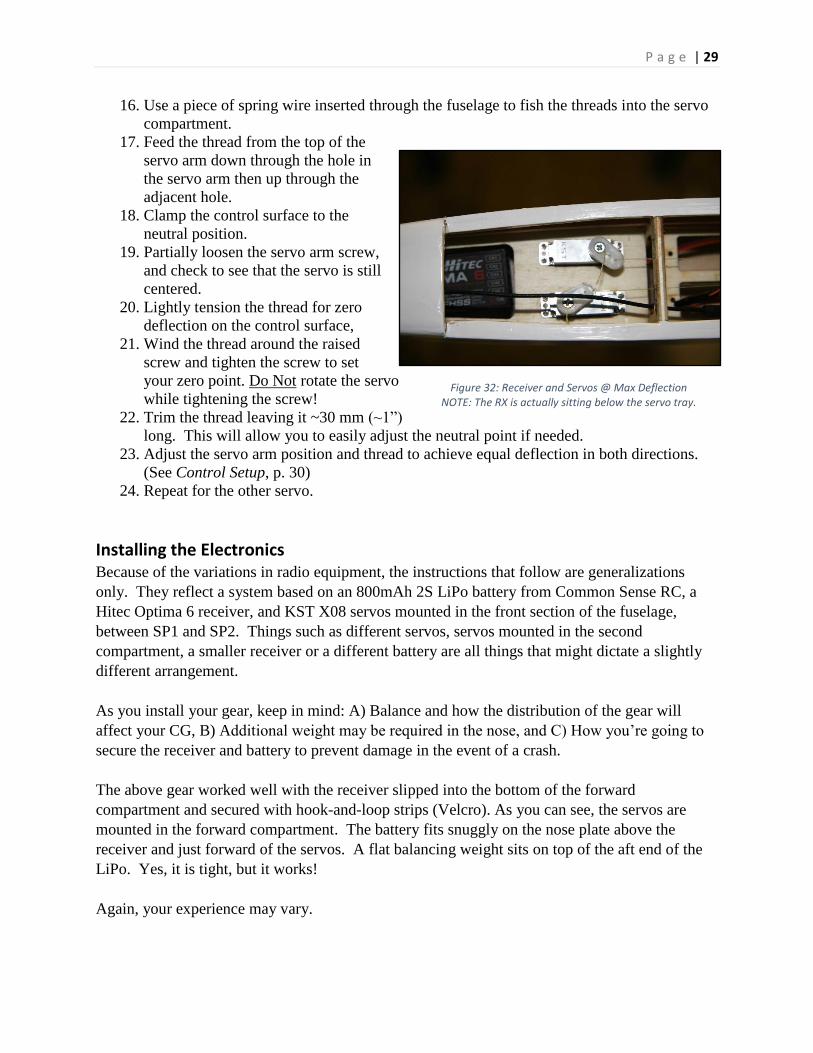
16. Use a piece of spring wire inserted through the fuselage to fish the threads into the servo
compartment.
17. Feed the thread from the top of the
servo arm down through the hole in
the servo arm then up through the
adjacent hole. 18. Clamp the control surface to the
neutral position. 19. Partially loosen the servo arm screw,
and check to see that the servo is still
centered.
20. Lightly tension the thread for zero
deflection on the control surface, 21. Wind the thread around the raised
screw and tighten the screw to set
your zero point. Do Not rotate the servo
while tightening the screw! 22. Trim the thread leaving it ~30 mm (~1”)
long. This will allow you to easily adjust the neutral point if needed.
23. Adjust the servo arm position and thread to achieve equal deflection in both directions.
(See Control Setup, p. 30)
24. Repeat for the other servo.
Installing the Electronics Because of the variations in radio equipment, the instructions that follow are generalizations
only. They reflect a system based on an 800mAh 2S LiPo battery from Common Sense RC, a
Hitec Optima 6 receiver, and KST X08 servos mounted in the front section of the fuselage,
between SP1 and SP2. Things such as different servos, servos mounted in the second
compartment, a smaller receiver or a different battery are all things that might dictate a slightly
different arrangement.
As you install your gear, keep in mind: A) Balance and how the distribution of the gear will
affect your CG, B) Additional weight may be required in the nose, and C) How you’re going to
secure the receiver and battery to prevent damage in the event of a crash.
The above gear worked well with the receiver slipped into the bottom of the forward
compartment and secured with hook-and-loop strips (Velcro). As you can see, the servos are
mounted in the forward compartment. The battery fits snuggly on the nose plate above the
receiver and just forward of the servos. A flat balancing weight sits on top of the aft end of the
LiPo. Yes, it is tight, but it works!
Again, your experience may vary.
Figure 32: Receiver and Servos @ Max Deflection NOTE: The RX is actually sitting below the servo tray.

P a g e | 30
Balancing The balance of an airplane can determine
whether or not you enjoy many hours of reward
for your effort or whether or not you bring
home the pieces in a plastic bag. Most pilots
are aware of the importance of establishing a
proper Center of Gravity (CG), but lateral
balance (side-to-side through the roll axis) is
also important.
Before balancing, you need to install the
adjustable tow hook in the provided slot in the
fuselage.
To install the hook:
1. Make a small slit in the covering over the fuselage slot in the bottom of the fuselage and
carefully seal the cut edges inside the edges of the slot.
2. Locate the tow hook parts.
3. Screw the 3-mm nut to the bottom of the tow hook and place one of the washers above it.
4. Insert the tow hook through the slot in the fuselage, then add the second washer and the
nylon insert lock nut on the inside of the fuselage.
5. For your maiden flight, position the tow hook ~7-mm (~1/4”) forward of the holes in the
fuselage covering that represent the CG point and tighten the nut. This may be adjusted
later for a more aggressive launch angle if desired.
To check the lateral balance:
1. Invert the plane and suspend it from the tow hook.
2. The model should remain level through the roll axis (left/right). If not, the easiest
solution is usually to add weight to the higher side. Do not be terribly concerned about
the nose or the tail dropping at this point.
Included in the kit is a Center of Gravity jig. This
works in conjunction with two holes bored through
the fuselage to balance the model at the designer’s
recommended CG starting point.
It works on the principle that if the wire transects the
fuselage where the CG should be, then when the
fuselage is placed into the jig, the model will pivot
forward or backward on the wire depending upon
whether the nose or the tail is lighter.
NOTE
TO SOME EXTENT, THE EXACT
LOCATION OF THE CENTER OF GRAVITY
IS A PILOT PREFERENCE. IT IS HIGHLY
RECOMMENDED THAT THE DESIGNER’S
LOCATION BE USED FOR THE FIRST FEW
FLIGHTS. THE CG MAY THEN BE
ADJUSTED TO THE PILOTS LIKING FOR
LATER FLIGHTS.
Figure 33: Center of Gravity Jig
P a g e | 31
To use the CG jig:
1. Locate the two small thru holes in the fuselage ~72-mm (~2.75”) from the wing leading
edge and just below the top stringer. Open them with a wire or pin.
2. With the wing attached and all the equipment
installed, insert the jig wire through the holes
in the jig and the fuselage thereby suspending
the fuse inside the jig.
3. Set the jig on a flat, steady surface and release
the fuselage. Observe if the nose drops, rises,
or stays balanced. A slight nose down
attitude is permissible for the first few flights.
4. Attempt to reposition the equipment forward
or backward to counteract any imbalance.
With the equipment listed in the previous
section, Installing Electronics, options for repositioning were limited. This necessitated
adding additional weight. Adding weight is normally the least desirable action, but at
times it cannot be avoided. If tail heavy, add the weight as far forward as you can, and
add absolutely no more than the minimum needed to bring the plane into balance at the
recommended CG. NOTE: Ensure that any weight you add is securely fixed into place!
5. If you wish to move the CG, drill additional holes in the fuselage at the desired point.
Control Setup The recommended throws for the Samba are as follows:
Elevator: +/- 15 – 20 mm (~9/16” – ~3/4”)
Rudder : +/- 25 – 30 mm (~15/16” – ~1-3/16”)
Spoiler: Up to 90°
It is recommended that these throws not be exceeded for the first few flights.
Many pilots also find it helpful to set exponential on their controls to make them less sensitive
around the center position. This is an aid to prevent overcontrolling the airplane, a common
difficulty with less experienced pilots. The exact procedure for setting Expo will vary from radio
to radio. See your transmitter manual. Similarly, the amount of Expo used will depend upon
pilot preferences.
Final Inspection & Test Toss
You’re almost there! Just a quick couple of checks and the test glide, and you’re ready to
maiden. It is assumed that you have already bound your transmitter and receiver and configured
your model to operate as you wish.
Figure 34: Balancing Using the CG Jig
P a g e | 32
Here are a few final check points:
1. Check the stab and fuse alignment one last time.
2. Check the CG.
3. Inspect for any loose covering.
4. Operate the elevator, rudder, and spoiler to ensure that their movement is correct.
5. Check the CG…again.
6. Using the procedures outlined for your transmitter and receiver, perform a range check.
7. Have you checked your CG?
When satisfied with your setup, turn on your transmitter and receiver, confirm operation of the
controls, and then gently toss the airplane straight ahead into the wind. NOTE: It is somewhat
easier if you have someone else actually toss the plane while you stand ready to make any
needed corrections. Repeat the toss as many times as necessary while adjusting rudder and
elevator trim to achieve a straight gently descending glide.
CONGRATULATIONS! Your Samba EVO is now ready for its first flight. May it be the first
of many!
We hope that you have enjoyed building the Samba EVO as much as we’ve enjoyed bringing it
to you. Please check out our website at: cad2cnc (http://www.cad2cnc.ch/) for additional kits
and building opportunities.
P a g e | 33
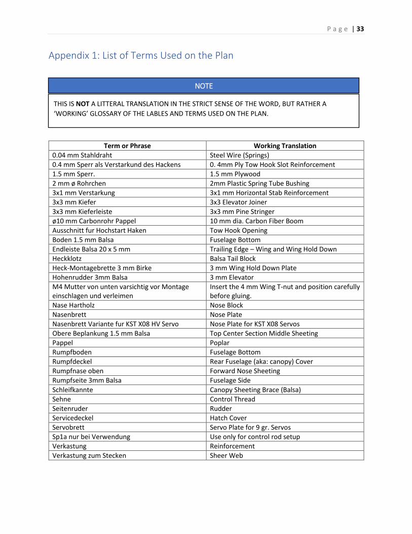
Appendix 1: List of Terms Used on the Plan
Term or Phrase Working Translation
0.04 mm Stahldraht Steel Wire (Springs)
0.4 mm Sperr als Verstarkund des Hackens 0. 4mm Ply Tow Hook Slot Reinforcement
1.5 mm Sperr. 1.5 mm Plywood
2 mm ø Rohrchen 2mm Plastic Spring Tube Bushing
3x1 mm Verstarkung 3x1 mm Horizontal Stab Reinforcement
3x3 mm Kiefer 3x3 Elevator Joiner
3x3 mm Kieferleiste 3x3 mm Pine Stringer
ø10 mm Carbonrohr Pappel 10 mm dia. Carbon Fiber Boom
Ausschnitt fur Hochstart Haken Tow Hook Opening
Boden 1.5 mm Balsa Fuselage Bottom
Endleiste Balsa 20 x 5 mm Trailing Edge – Wing and Wing Hold Down
Heckklotz Balsa Tail Block
Heck-Montagebrette 3 mm Birke 3 mm Wing Hold Down Plate
Hohenrudder 3mm Balsa 3 mm Elevator
M4 Mutter von unten varsichtig vor Montage einschlagen und verleimen
Insert the 4 mm Wing T-nut and position carefully before gluing.
Nase Hartholz Nose Block
Nasenbrett Nose Plate
Nasenbrett Variante fur KST X08 HV Servo Nose Plate for KST X08 Servos
Obere Beplankung 1.5 mm Balsa Top Center Section Middle Sheeting
Pappel Poplar
Rumpfboden Fuselage Bottom
Rumpfdeckel Rear Fuselage (aka: canopy) Cover
Rumpfnase oben Forward Nose Sheeting
Rumpfseite 3mm Balsa Fuselage Side
Schleifkannte Canopy Sheeting Brace (Balsa)
Sehne Control Thread
Seitenruder Rudder
Servicedeckel Hatch Cover
Servobrett Servo Plate for 9 gr. Servos
Sp1a nur bei Verwendung Use only for control rod setup
Verkastung Reinforcement
Verkastung zum Stecken Sheer Web
NOTE
THIS IS NOT A LITTERAL TRANSLATION IN THE STRICT SENSE OF THE WORD, BUT RATHER A
‘WORKING’ GLOSSARY OF THE LABLES AND TERMS USED ON THE PLAN.
![13885 - Uma história do samba - 05 [emendas] · O samba é pai do prazer O samba é filho da dor. Caetano Veloso, “ Desde que o samba é samba” 13885 - Uma história do samba](https://img.pdfslide.net/doc/110x75/5ae903e07f8b9a290490f3a0/13885-uma-histria-do-samba-05-emendas-samba-pai-do-prazer-o-samba-filho-da.jpg)