Embed Size (px)
Citation preview
P-A-X/PABX SWITCHBOARD
TYPE 50
~ ®
AUTOM·ATIC
Technical 3 2 2 bulletin
ELECTRIC ORIGINATORS OF THE DIAL TELEPHONE
TCI Library www.telephonecollectors.info
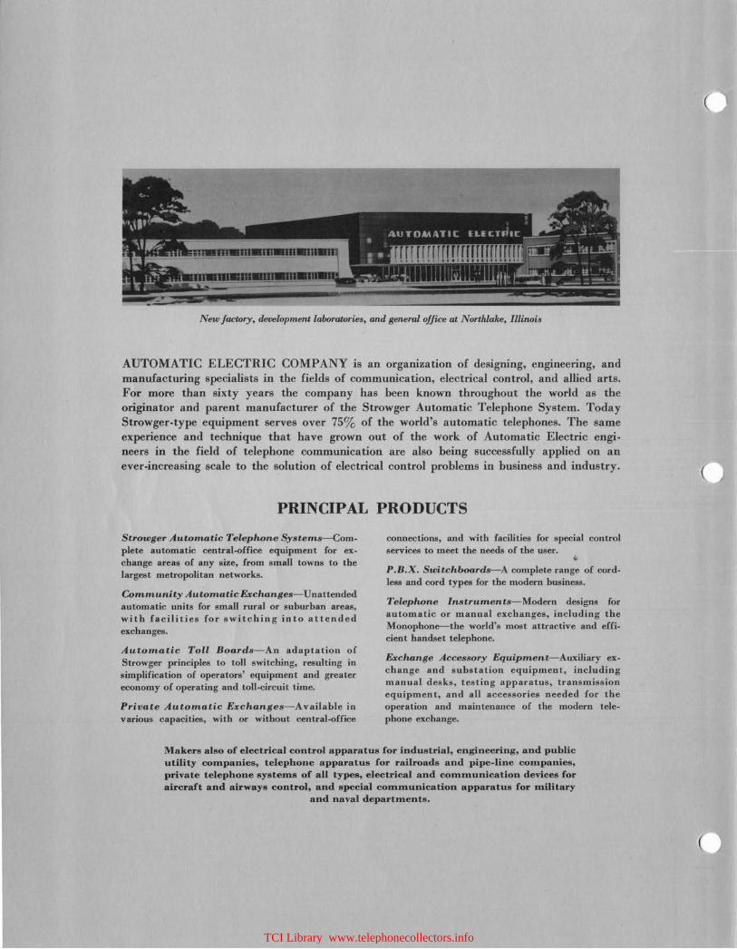
New factory, development laboratories, and general office at Northlake, Illinois
AUTOMATIC ELECTRIC COMPANY is an organization of designing, engineering, and manufacturing specialists in the fields of communication, electrical control, arid allied arts. For more than sixty years the company has been known throughout the world as the originator and parent manufacturer of the Strowger Automatic Telephone System. Today Strowger-type equipment serves over 75% of the world's automatic telephones. The same experience and technique that have grown out of the work of Automatic Electric engineers in the field of telephone communication are also being successfully applied on an ever-increasing scale to the solution of electrical control problems in business and industry.
PRINCIPAL PRODUCTS
Strowger Automatic Telephone Systems-Complete automatic central.office equipment for ex· change areas of any size, from small towns to the largest metropolitan networks.
Community Automatic Exchanges-Unattended automatic units for small rural or suburban areas, with facilities for switching into attended exchanges.
Automatic Toll Boards-An adaptation of Strowger principles to toll switching, resulting in simplification of operators' equipment and greater economy of operating and toll.circuit time.
Private Automatic Exchanges-Available in various capacities, with or without central-office
connections, and with facilities for special control services to meet the needs of the user. .. P.B.X. Switchboards-A complete range of cordless and cord types for the modern business.
Telephone Instruments-Modern designs for automatic or manual exchanges, including the Monophone--the world's most attractive and effi. cient handset telephone.
Exchange Accessory Equipment-Auxiliary exchange and substation equipment, including manual desks, testing apparatus, transmission equipment, and all accessories needed for the operation and maintenance of the modern telephone exchange.
Makers also of electrical control apparatus for industrial, engineering, and public utility companies, telephone apparatus for railroads and pipe-line companies, private telephone systems of all types, electrical and communication devices for aircraft and airways control, and special communication apparatus for military
and naval departments.
(
TCI Library www.telephonecollectors.info

P-A-X/PABX SWITCHBOARD
TYPE 50
Bulletin 322
AUTOMATIC ELECTRIC
TCI Library www.telephonecollectors.info
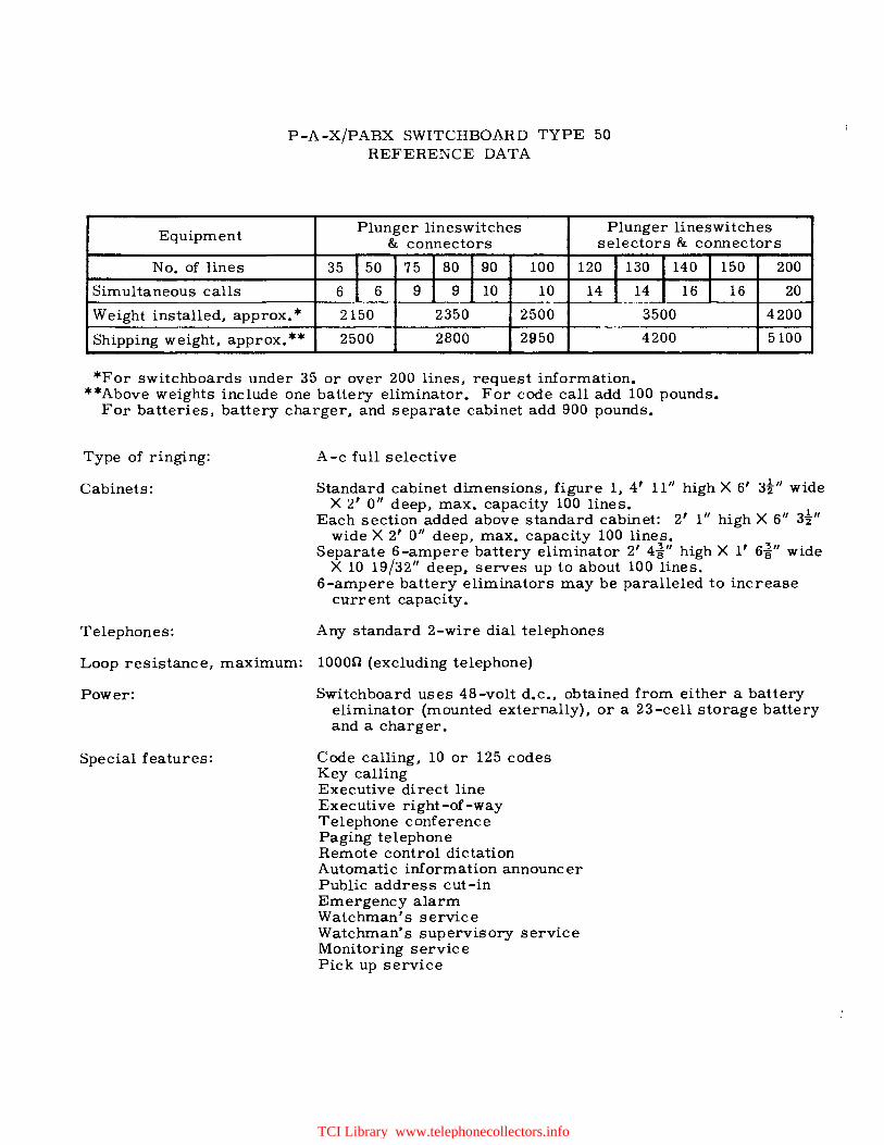
P-A-X/PABX SWITCHBOARD TYPE 50 REFERENCE DATA
Equipment Plunger lineswitches Plunger lineswitches & connectors selectors & connectors
No. of lines 35 50 75 80 90 100 120 130 140 150 200
Simultaneous calls 6 6 9 9 10 10 14 14 16 16 20
Weight installed, approx.* 2150 2350 2500 3500 4200
Shipping weight, approx.** 2500 2800 2950 4200 5100
*For switchboards under 35 or over 200 lines, request information. **Above weights include one battery eliminator. For code call add 100 pounds.
For batteries, battery charger, and separate cabinet add 900 pounds.
Type of ringing: A-c full selective
Cabinets: Standard cabinet dimensions, figure 1, 4' 11" high X 6' 3!" wide X 2' O" deep, max. capacity 100 lines.
Each section added above standard cabinet: 2' 1" high X 6 11 3!" wide X 2' O" deep, max. capacity 100 lines.
Separate 6-ampere battery eliminator 2' 4i" high X 1' 6i" wide X 10 19/32" deep, serves up to about 100 lines.
6-ampere battery eliminators may be paralleled to increase current capacity.
Telephones: Any standard 2-wire dial telephones
Loop resistance. maximum: 10000 (excluding telephone)
Power: Switchboard uses 48-volt d.c., obtained from either a battery eliminator (mounted externally). or a 23-cell storage battery and a charger.
Special features: Code calling, 10 or 125 codes Key calling Executive direct line Executive right-of -way Telephone conference Paging telephone Remote control dictation Automatic information announcer Public address cut-in Emergency alarm Watchman's service Watchman's supervisory service Monitoring service Pick up service
TCI Library www.telephonecollectors.info
CONTENTS
1. INTRODUCTION.
2. AUXILIARY SERVICES
2:01 Code calling (10 or 125 codes) 2.02 Key-calling 2,03 Executive direct-line 2.04 Executive right-of-way 2.05 Telephone conference . • • 2.06 Paging telephone (area communication) 2.07 Remote-control dictation 2.08 Automatic information announcer 2.09 Public-address cut-in 2.10 Emergency alarm 2.11 Watchman's service . • 2.12 Watchman's supervisory service
3. SWITCHING EQUIPMENT
4. LINESWITCH TRUNK OUTLETS
5. SWITCHBOARD MOUNTING ARRANGEMENTS
6. POWER SUPPLY SHELF
7. LINESWITCHES
8. MASTER SWITCH
9. CONNECTORS
9.1 Types of connector 9.2 Individual-line, isolated-service connector 9.3 Rotary or trunk-hunting connector 9.4 Local and switch-thru connectors
10. TWO-HUNDRED-LINE TYPE CONNECTORS
11. SELECTORS
12, POWER SUPPLY SHELF.
12.1 12.2 12.3 12.4 12.5
Ringing converter . Ringing interrupter Tone and charge-control relays Code-call equipment Power panel
13. SUPERVISORY ALARM EQUIPMENT
13.1 Space for extra equipment'
14. TELEPHONE INSTRUMENTS
15, TELEPHONE NUMBERING
16, SWITCHBOARD CABINET
17. ASSOCIATED EQUIPMENT
17 .1 17.2 17.3 17.5 17.6 17.7
Protection Terminal equipment Storage battery or battery eliminator Rectifier . Direct charge • Power-control apparatus
18, METHOD OF OPERATION
•.
18.1 Local calls - connector and selector systems 18.2 Calls to other switchboards •
19. FLOOR PLANS .
WEIGHTS AND MEASUREMENTS •
MONOPHONE TYPE 80
MONOPHONE TYPE 90
Page
1
1 1 1 1 2 2 2 2 2 2 2 2
2
2
2
3
4
6
7
7 7 8 8
8
9
10
10 10 10 11 11
11
11
11
12
12
12
12 12 12 12 13 13
13
13 14
16
17
18
19
TCI Library www.telephonecollectors.info
(
(
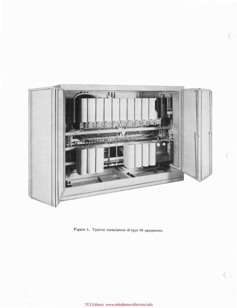
Figure 1. Typical installation of type 50 equipment.
(
TCI Library www.telephonecollectors.info
P-A-X/PABX SWITCHBOARD TYPE 50
1. INTRODUCTION
The Type 50 P-A-X is a full-automatic, secretservice, machine-ringing, private telephone switchboard. It is particularly adapted for use in establishments where the initial requirements are between 35 and 100 lines and the probable ultimate growth will not ordinarily exceed 200 lines. Plunger type, self-aligning line switches are used in connection with connectors or, selectors and connectors.
In the case of hospitals, schools, etc. where the ultimate of 100 lines is already fixed, 100 lines can be accommodated with the ordinary onehundred line type connector, but if the ultimate number of lines is expected to be between 100 and 200, then the two-hundred line type connector should be specified. In that event up to 200 lines can be accommodated without introducing selectors.
Should the initial requirements be close to 200 lines, which is the maximum capacity of the twohundred line type connectors, and the indications are that the plant will soon increase beyond 200 lines, then selectors should be specified for the initial scheme, with 100 line type connectors.
An ultimate of 100 lines can be accommodated with the ordinary one-hundred line type connector. A 35 line, stock type 50 addition is used to expand boards from 100 lines to over 100 lines by converting the board to a selector system.
For a selector system, using 100 line type connectors three digits would be required, the same as for a system using two-hundred-line type connectors. Regardless of the initial number of lines provided, additional line switches, selectors and connectors with their respective shelves and banks and switchboard sections may be erected, as and when required, to increase the capacity of the exchanges to 400 lines, which is considered as the ultimate for this type of installation.
Should selectors be decided upon for the initial, or any subsequent stage, these are assembled on shelves and would be housed in sectional type cabinets. The selectors, with their respective banks and shelves, are mounted 10 per shelf, and the quantity to be furnished for an installation will be determined by the traffic requirements.
This Type P-A-X switchboard can be arranged for intercommunication service only or for connection with other existing private manual or automatic switchboards--or any such switchboards which may be required to be installed at some future date.
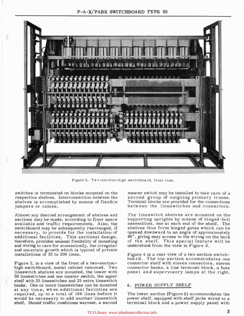
Figure 1 is a general view of a typical installation of Type 50 equipment, illustrating the features of the metal cabinet with swinging collapsible doors (both front and rear), which allows easy access to the equipment and wiring. This illustration is a two section high cabinet which would have an ultimate capacity, of 50 line switches, one power and one connector shelf in the rear. The shelf arrangement and methods of assembly are illustrated on page 15, Figure 14 A to G.
2. AUXILIARY SERVICES
In addition to providing rapid and accurate intercommunication between the telephones connected to one or more private switchboards, provision may be made for the following auxiliary services.
2.01 Code calling ( 10 or 125 codes)G
Permits a P-A-X user to locate promptly and to talk with any person who is not at his regular telephone and who has been assigned a code ring. The desired party can answer the code ring from any nearby telephone by dialing a predetermined number.
2.0 2 Key-calling
By depressing a key in a small cabinet located near the telephone permits an executive to call some one with whom he must talk frequently without dialing.
2.03 Executive Direct-Line
Similar to Key calling except that he can use his P-A-X telephone or a speaker and microphone unit whichever he prefers.
2.04 Executive Right-of-Way
Lines designated executives the privilege of cutting in on a busy connection and holding conversation with one or both of the engaged parties.
1 TCI Library www.telephonecollectors.info
P-A-X/PABX SWITCHBOARD TYPE 50
2.05 Telephone Conference
Provides for a telephone conference at any time between a given number of P-A-X subscribers with the conferees remaining at their regular telephones.
2.06 Paging Telephone (Area Communication)
Establishes communication immediately with any number of others throughout extended areas. It consists of a special loudspeaker, microphone and a two-way amplifying unit. They are able to reply by merely facing towards one of the microphone-loudspeakers, and speaking.
2.07 Remote Control Dictation
This service permits by merely changing the handset of selected stations to dictate to their existing dictation machine providing "dictation by telephone''.
2_08 Automatic Information Announcer
Provides voice recording of any message and Automatic repetltion of that message to any person dialing the P-A-X "message repeater" number.
2.09 Public Address Cut-in
Provides the convenience of using an existing public address system by allowing announcement to be made from any P-A-X telephone.
2.10 Emergency Alarm
Permits each P-A-X telephone to become an alarm, or fire reporting station; whereby quick action can be taken in an emergency.
2.11 Watchman's Service
Provides for the recording of watchmen's calls.
2.12 Watchman's Supervisory Service
Provides for the supervision of watchmen's routes.
Several of the above services can be added to an existing Type 50 P-A-X without alteration or increase in quantities of automatic equipment. However, some of these services require a small amount of additional equipment, relay groups, power relays, etc. In the case of the watchman's supervisory service, emergency alarm or fire alarm service, these require that the switch-thrutype connector shall be used, when selectors are not used.
Consideration should be given to these requirements at the time the initial installation is being planned.
2
The Code Call Relay Group is mounted on two switch bases wired and arranged to mount on the power shelf on a shelf -jack which forms a part of the initial installation.
3. SWITCHING EQUIPMENT
The switching equipment includes: - self-aligning plunger type line switches (one for each line in service); one master switch for each group of outgoing primary line switch trunks; a connector or selector for each outgoing line switch trunk; a ringing converter; a ringing interrupter; a tone and charge control relay group; and a power supply panel.
The line switches, connectors, selectors and other equipment in the switchboard, excepting the power supply panel, are wired to multi-contact jacks which facilitate mounting and demounting, for installation, inspection and repair.
When special service equipment; such as Watchman's Service, Conference Service, Emergency Alarms, Executive Right-of-Way, are specified; the associated apparatus may be mounted on a separate unit and located near the switchboard or when circumstances permit, made a unit of the P-A-X.
4. LINESWITCH TRUNK OUTLETS
The number of trunk outlets required from the lineswitches to the connectors (or selectors) can best be determined by a study of the telephone traffic of the individual organization. In cases where such data is not available, the number of lineswitch outlets recommended for various line capacities, are as follows:
Line Switches
35 50 75 80 90
100 120 130 140 150 200
Total Number of Links
6 6 9 9
10 10 14 14 16 16 20
5. SWITCHBOARD MOUNTING ARRANGEMENTS
The Type 50 Switchboards are of the "sectional" design, with the switch shelves mounted on onepiece end frame. Shelves are mounted on both sides of the end frame to form a double sided 1
unit. The shelf units are housed, one above the other, in a metal type cabinet with hinged doors on both sides, to provide ready access to the equipment and wiring. All wiring to and from the
TCI Library www.telephonecollectors.info
(
(
(
P-A-X/PABX SWITCHBOARD TYPE 50
Figure 2. Tw o -s ect i o n-hig h s wi tc hb oard , front v iew .
switches is terminated on blocks mounted on the respective shelves. Interconnection between the shelves is accomplished by means of flexible jumpers or cables.
Almost any desired arrangement of shelves and sections may be made, according to floor space available and traffic requirements. Also, the switchboard may be subsequently rearranged, if necessary, to provide for the installation of additional facilities. This sectional design, therefore, provides unusual flexibility of mounting and wiring to care for economically, the irregular and uncertain growth which is typical of private installations of 35 to 200 lines.
Figure 2, is a view of the front of a two-sectionhigh switchboard, metal cabinet removed. Two lineswitch shelves are mounted, the lower with 50 lineswitches and one master switch, the upper shelf with 25 lineswitches and 25 extra lineswitch banks. One or more lineswitches can be mounted at any time, when additional facilities are required, up to a total of 100 lines before it would be necessary to add another lineswitch shelf. Should traffic conditions warrant, a second
master switch may be installed to take care of a second group of outgoing primary trunks . Terminal blocks are provided for the connections between the lines witc hes and conn e ctors.
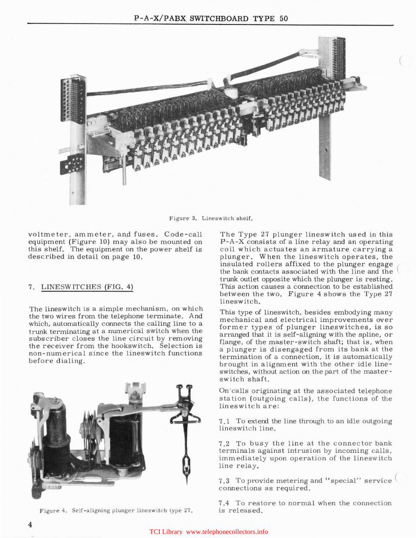
The lineswitch shelves are mounted on the· supporting uprights by means of hinged-bolt assemblies , one at each end of the shelf. The shelves thus form hinged gates which can be opened downward to an angle of approximately 90°, giving easy access to the wiring on the back of the shelf. This special feature will be understood from the view in Figure 3.
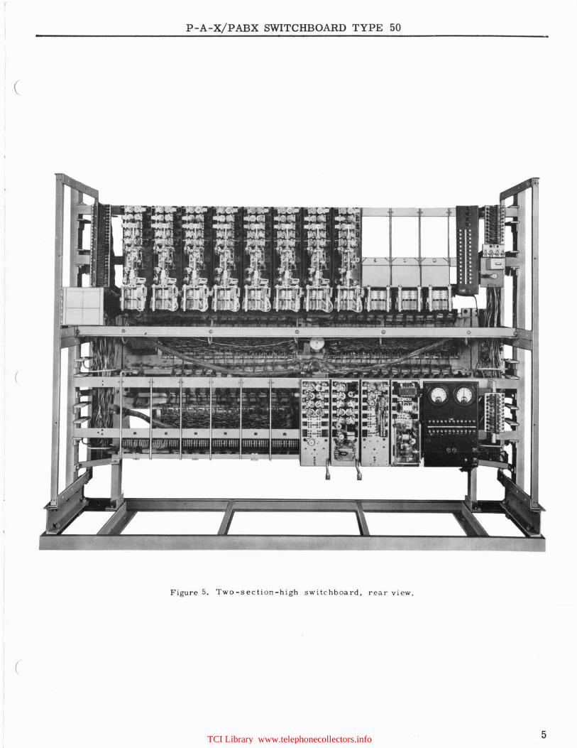
Figure 4 is a rear view of a two section switchboard. The top section accommodates one connector shelf with eleven connectors, eleven connector banks , a line terminal block, a fuse panel and supervisory lamps at the right.
6. POWER SUPPLY SHELF
The lower section (Figure 5) accommodates the power shelf, equipped with shelf jacks wired to a terminal block and a power supply panel with
3 TCI Library www.telephonecollectors.info
P-A-X/PABX. SWITCHBOARD TYPE 50
(
Figure 3. Lineswitch shelf.
voltmeter, ammeter, an.ct fuses. Code-call equipment (Figure 10) may also be mounted on this shel f. The equipment on the power shelf is described in detail on page 10.
7. LINESWITCHES (FIG. 4)
The lineswitch is a simple mechanism, on which the two wires from the telephone terminate. And which, automatically connects the calling line to a trunk terminating at a numerical switch when the subscriber closes the line circuit by removing the receiver from the hookswitch. Selection is non-numerical since the lineswitch functions before dialing.
Figure 4. Se lf-aligning plunger lines w i t c h type 27.
4
The Type 27 plunger lineswitch used in this P -A-X consists of a line relay and an ope.rating coil which actuates an armature carrying a plunger. When the lineswitch operates, the insulated rollers affixed to the plunger engage ( the bank contacts associated with the line and the trunk outlet opposite which the plunger is resting. This action causes a connection to be established between the two. Figure 4 shows the Type 27 lineswitch.
This type of lineswitch, besides embodying many mechanical and electrical improvements over former types of plunger lineswitches, is so arranged that it is self-aligning with the spline, or flange, of the master-switch shaft; that is, when a plunger is disengaged from its bank at the termination of a connection, it is automatically brought in alignment with the other idle lineswitches, without action on the part of the master -switch shaft.
On ·calls originating at the associated telephone station (outgoing calls), the functions of the lineswitch are:
7. 1 To extend the line through to an idle outgoing lineswi1.c h line.
7 .2 To busy the line at the connector bank terminals against intrusion by incoming calls , immediately upon operatio n of the lineswitch line relay .
7 . 3 To provide metering and "special" service ( connections as required .
7 .4 To restore to normal when the c onnection is released.
TCI Library www.telephonecollectors.info
P-A-X/PABX SWITCHBOARD TYPE 50
(
(
Figure 5. Two-section-high switchboard, rear view.
(
5 TCI Library www.telephonecollectors.info

P-A-X/PABX SWITCHBOARD TYPE 50
On calls to the associated telephone station (incoming calls), the functions of the lineswitch are:
7 . 5 To free the line of all attachments.
7 .6 To prevent its plunger from engaging an outgoing lineswitch trunk.
7. 7 To busy the line from intrusion by other calls, either incoming or outgoing.
A characteristic of the Type 27 lineswitch is that in case an "open" primary trunk is encountered, the lineswitch will immediately withdraw from the faulty connection and automatically re-establish connection with another idle trunk.
The lineswitc hes are mounted on shelves in groups of twenty-five, two groups per shelf or a total of fifty switches. The shelves are mounted in a horizontal position, as shown in Fig. 2. Access to the lineswitch bank wiring, and to the rear of power and connector shelves, is accomplished by swinging the lineswitch shelves downward. See Figure 3.
The Type 27 lineswitch is fully described in Engineering Bulletin 305, copies of which will be furnished upon request.
8. MASTER SWITCH
In describing the lineswitch it was stated that, a calling line would be connected to an idle trunk by the plunger, in response to the closing of the line circuit. Simultaneously, the plunger action closes a circuit through the Master-Bank, causing the Master Switch to operate one step and m ec hanica lly move all idle lineswitch plungers to a position oppo,site an idle trunk. This control is through the movement of the plunger guide shaft. Each time a trunk is engaged, the master switch immediately moves, or steps the guide shaft which in turn carries with it the plungers of all idle lineswitches, to a position opposite an idle trunk. The plunger-type lines witch is thus preselecting in opera ti on; that is, the idle trunk is selected prior to the origin of the call.
The functions of the master switch may be summarized as follows:
8.1 Provide ''supervised'' positive battery to the associated lineswitches.
8.2 Seek an idle trunk whenever a lineswitch engages the pres elected trunk.
8.3 Prevent any lineswitch from plunging while the master switch is seeking an idle trunk.
6
8.4 Lock the plunger guide shaft in the trunk position chosen.
When specified, a "peg count" meter is connected into the master switch circuit to register each time a lineswitch engages a trunk outlet, thus recording all calls originating from the telephone stations associated with the P-A-X.
If all trunk outlets are busy, the master switch will not start searching until an idle trunk is available. In this event the absence of dial tone will indicate to the calling subscriber that the equipment is not ready to receive his call and dialing should not commence until dial tone is heard.
Figure 6 is a photographic view of an unmounted master switch and clearly shows its mechanical structure, A feature of design is, that the relays associated with the master switch are mounted on a plate separate from the masterswitch mechanism and magnets.
Figure 6. Master switch and control relays.
(
(
(
TCI Library www.telephonecollectors.info
(
(
(
P-A-X/PABX SWITCHBOARD TYPE 50
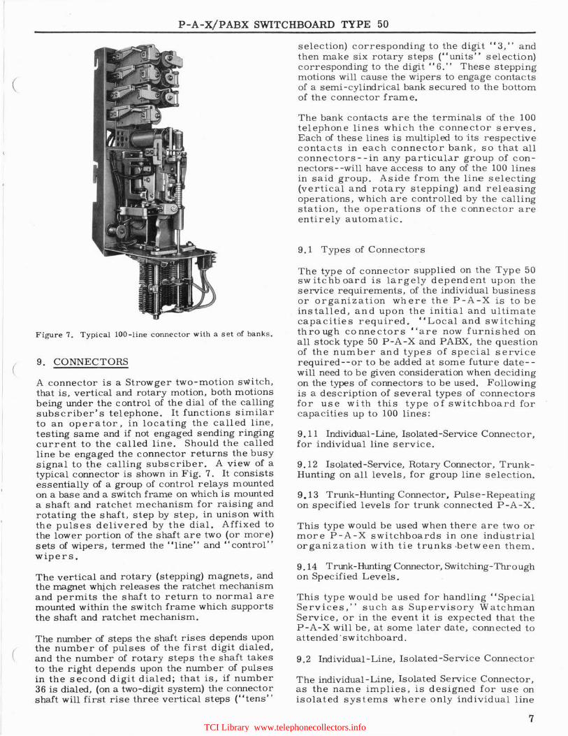
Figure 7. Typical 100-line connector with a s e t of banks.
9. CONNECTORS
A connector is a Strowger two-motion switch, that is, vertical and rotary motion, both motions being under the control of the dial of the calling subscriber's telephone. It functions similar to an opera tor, in lo ca ting the called line, testing same and if not engaged sending ringing current to the called line. Should the called line be engaged the connector returns the busy signal to the calling subscriber. A view of a typical connector is shown in Fig. 7. It consists essentially of a group of control relays mounted on a base and a switch frame on which is mounted a shaft and ratchet mechanism for raising and rotating the shaft, step by step, in unison with the pulses delivered by the dial. Affixed to the lower portion of the shaft are two (or more) sets of wipers, termed the "line" and " control" wipers,
The vertical and rotary (stepping) magnets, and the magnet wh!ch releases the ratchet mechanism and permits the shaft to return to normal are mounted within the switch frame which supports the shaft and ratchet mechanism.
The number of steps the shaft rises depends upon the number of pulses of the first digit dialed, and the number of rotary steps the shaft takes to the right depends upon the number of pulses in the second digit dialed; that is, if number 36 is dialed, (on a two-digit system) the connector shaft will first rise three vertical steps ("tens''
selection) corresponding to the digit "3," and then make six rotary steps ("units" selection) corresponding to the digit "6." These stepping motions will cause the wipers to engage contacts of a semi-cylindrical bank secured to the bottom of the connector frame.
The bank contacts are the terminals of the 100 telephone lines which the connector serves. Each of these lines is multipled to its respective contacts in each connector bank, so that all connectors--in any particular group of connectors- -will have access to any of the 100 lines in said group. Aside from the line selecting (vertical and rotary stepping) and releasing operations, which are controlled by the calling station, the operations of the connector are entirely automatic.
9.1 Types of Connectors
The type of connector supplied on the Type 50 switchboard is largely dependent upon the service requirements, of the individual business or organization where the P-A-X is to be installed, and upon the initial and ultimate capacities required. "Local and switching through connectors "are now furnished on all stock type 50 P-A-X and PABX, the question of the number and types of special service required--or to be added at some future date-will need to be given consideration when deciding on the types of connectors to be used. Following is a description of several types of connectors for use with this type of switchboard for capacities up to 100 lines:
9. 11 Individual - Line, Isolated-Service Connector, for individual line service.
9.12 Isolated-Service, Rotary Connector, TrunkHunting on all levels, for group line selection.
9.13 Trunk-Hunting Connector, Pulse-Repeating on specified levels for trunk connected P-A-X.
This type would be used when there are two or more P-A-X switchboards in one industrial organization with tie trunks ·between them.
9.14 Trunk-Hunting Connector, Switching- Through on Specified Levels.
This type would be used for handling " Special Services , '' such as Supervisory Watchman Service, or in the event it is expected that the P-A-X will be , a t some later date, connected to attended · switchboard .
9 .2 Individual-Line, Isolated-Service Connector
The individual -Line, Isolated Service Connector, as the name implies, is designed for use on isolated systems where only individual line
7 TCI Library www.telephonecollectors.info
P-A-X/PABX SWITCHBOARD TYPE 50
service is provided. In this case only two digit numbering is required, up to a capacity of 100 lines.
Its major functions are:
9. 21 Immediately upon seizure by the calling line, to hold the preceding switches operated, make itself busy, start the "dial tone" equipment and connect dial-tone to the calling line.
9.22 In response to the pulses from the dial on the telephone of the calling line, to direct and connect its wipers to the line being called, and start the ringing and busy machines.
9.23 Test the dialed line and if not busy, ring the dialed station at the same time connect ring-back tone to the calling line. If the dialed line is busy, prevent intrusion on the dialed line and give the dialing party the busy tone.
9.24 Remove the ringing current from the dialed line after the called subscriber answers, connect the calling and called lines together and furnish transmission battery to both parties.
9.25 This connector returns to normal position after the calling subscriber opens the line by replacing his receiver on the switchhook. This allows the lineswi tch plunger to return to the control of the master switch.
9.26 In case the connector shaft does not return to normal after the calling party replaces his receiver, a circuit is established to a visible and audible signal.
9.3 Rotary or Trunk-Hunting Connector
The Trunk-Hunting or Rotary Connector is similar in operation to the regular Individual-Line, Isolated Service Connedor. lt'performs all of the functions as enumerated under the heading ''Individual Line, I.solated Service Connector.'' In addition it is so arranged that on the horizontal (rotary) movement across the bank terminals, after it has ceased rotating under the control of the dial, it will continue to rotate arrl automatically select an idle line from the sequence group chosen by the dial. This feature is required where the number of incomi.ng calls to any department is greater than that which a single line is capable of handling.
Only the number of the first line in a multiplelin e group is listed in the directory. When this number is dialed and the first line tests busy, the conn.ector automatic ally steps the wipers to the next non-busy line of the group. Should all lines in the group test busy, a busy signal will be heard by the calling person. Since all numbers ending in "O" appear as the last set of terminals at the right-hand side of
8
the connector bank levels, these numbers cannot be employed as the listed number of a multipleline group.
9.4 Local and Switch-through Connectors.
These switches are combinations of selectors and connectors. On the upper levels, used for trunks and tie lines, normal-post-springs cause automatic rotary and switch-through after only 1 digit has been dialed. For calls to the station lines in the other (lower) levels, 2 digits are dialed.
Its major functions are: -
9.41 Hold the preceding switches operated and make itself busy.
9.42 Move the wipers to the dialed level.
9.43 If the dialing line is not entitled to trunk hunting service, give the dialing party the busy tone.
9.44 If the dialing party is entitled to trunk hunting service automatically to cut-in on the dialed level.
9.45 Automatically hunt for a free trunk.
9.46 Seize the first free trunk encountered. Make the seized trunk busy and extend the dialing line directly throtigh to the seized trunk without attachments.
9.47 Release when the dialing party disconnects. Open a part of the chain circuit.
9.48 Remove the wipers from the banks when all trunks are busy.
9.49 Give the dialing party the busy tone.
9.50 Release when the dialing party disconnects.
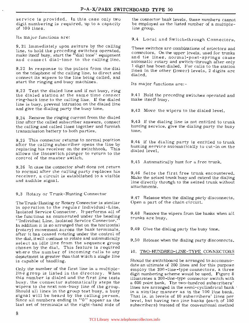
10. TWO-HUNDRED-LINE-TYPE CONNECTORS
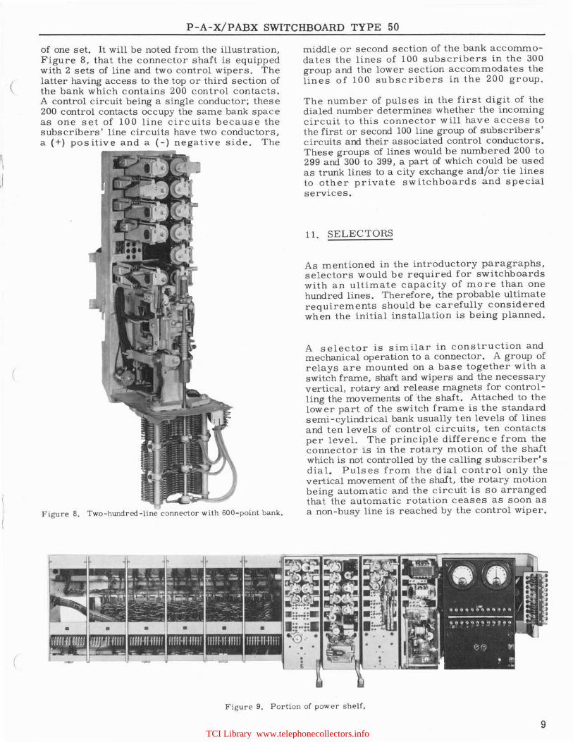
Should the switchboard be arranged to accommodate an ultimate of 200 lines and for this purpose employ the 200 -line-type connectors, a three digit numbering scheme would be used. Figure 8 illustrates a 200-line-type connector switch with a 600 point bank. The two-hundred subscribers' lines are arranged in the semi-cyclindrical bank 1
in a similar manner as in the 100 line bank. That is, in levels of 10 subscribers' lines per level, but having two line banks (each of 100 subscribers) instead of the conventional met.hod
TCI Library www.telephonecollectors.info
\ ,I
(
(
(
P-A-X/PABX SWITCHBOARD TYPE 50
of one set. It will be noted from the illustration, Figure 8, that the connector shaft is equipped with 2 sets of line and two control wipers. The latter having access to the top or third section of the bank which contains 200 control contacts. A control circuit being a single conductor; these 200 control contacts occupy the same bank space as one set of 100 line circuits because the subscribers' line circuits have two conductors, a(+) positive and a (-)negative side. The
Figure 8. Two-hundred-line connector with 600-point bank.
middle or second section of the bank accommodates the lines of 100 subscribers in the 300 group and the lower section accommodates the lines of 100 subscribers in the 200 group.
The number of pulses in the first digit of the dialed number determines whether the incoming circuit to this connector will have access to the first or second 100 line group of subscribers' circuits and their associated control conductors. These groups of lines would be numbered 200 to 299 and 300 to 399, a part of which could be used as trunk lines to a city exchange and/or tie lines to other private switchboards and special services.
11. SELECTORS
As mentioned in the introductory paragraphs, selectors would be required for switchboards with an ultimate capacity of more than one hundred lines. Therefore, the probable ultimate requirements should be carefully considered when the initial installation is being planned.
A selector is similar in construction and mechanical operation to a connector. A group of relays are mounted on a base together with a switch frame, shaft and wipers and the necessary vertical, rotary an:I. release magnets for controlling the movements of 'the shaft. Attached to the lower part of the switch frame is the standard semi-cylindrical bank usually ten levels of lines and ten levels of control circuits, ten contacts per level. The principle difference from the connector is in the rotary motion of the shaft which is not controlled by the calling subscriber's dial. Pulses from the dial control only the vertical movement of the shaft, the rotary motion being automatic and the circuit is so arranged that the automatic rotation ceases as soon as a non-busy line is reached by the control wiper.
Figure 9. Portion of power shelf.
9 TCI Library www.telephonecollectors.info
P-A-X/PABX SWITCHBOARD TYPE 50
The major functions of a selector are:
11. 1 Immediately upon seizure, to hold the line -switch operated, make itself busy, and connect dial tone to the calling line.
11.2 In response to the pulses from the dial of the calling telephone to raise the shaft (vertical motion) so that the wipers are opposite the level corresponding to the digit dialed. Automatic rotation then takes place, the wipers are stepped horizontally and each contact in the level is tested until a vacant contact is reached. Rotation then ceases and the line and control circuits are connected through the wipers and bank contacts to the succeeding switch or tie line.
11. 3 To release when the calling person opens the line circuit by restoring the receiver to the switch hook.
12. POWER SUPPLY SHELF
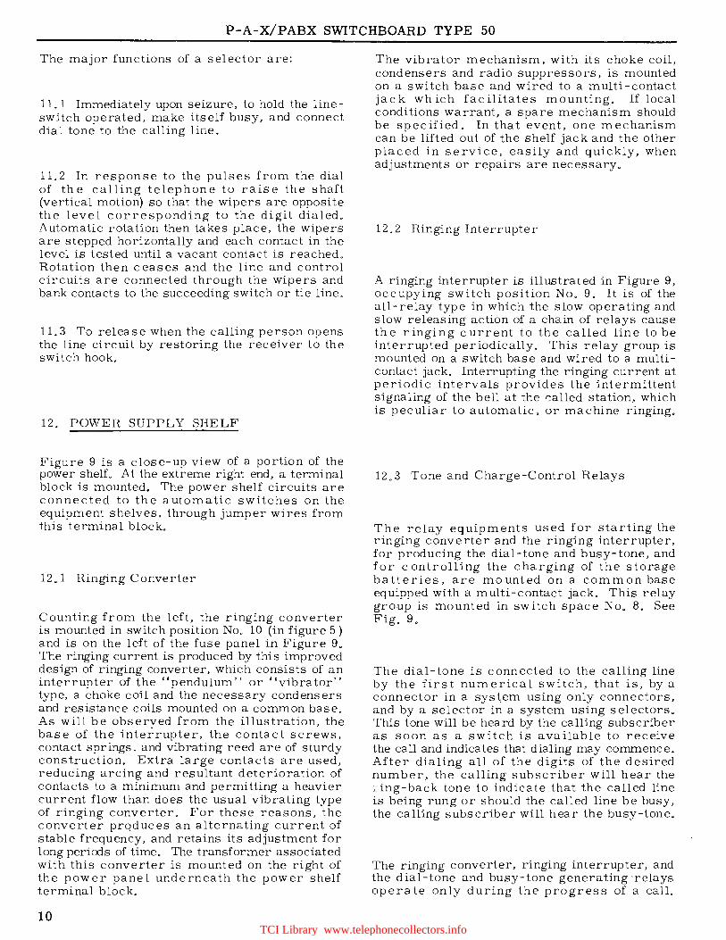
Figure 9 is a close-up view of a portion of the power shelf. At the extreme right end, a terminal block is mounted. The power shelf circuits are connected to the automatic switches on the equipment shelves, through jumper wires from this terminal block.
12. l Ringing Converter
Counting from the left, the ringing converter is mounted in switch position No. 10 (in figure 5) and is on the left of the fuse panel in Figure 9. The ringing current is produced by this improved design of ringing converter, which consists of an interrupter of the "pendulum" or "vibrator" type, a choke coil and the necessary condensers and resistance coils mounted on a common base. As will be observed from the illustration, the base of the interrupter, the contact screws, contact springs, and vibrating reed are of sturdy construction. Extra large contacts are used, reducing arcing and resultant deterioration of contacts to a minimum and permitting a heavier current flow than does the usual vibrating type of ringing converter. For these reasons, the converter produces an alternating current of stable frequency, and retains its adjustment for long periods of time. The transformer associated with this converter is mounted on the right of the power pane 1 underneath the power shelf terminal block.
10
The vibrator mechanism, with its choke coil, condensers and radio suppressors, is mounted on a switch base and wired to a multi-contact jack which facilitates mounting. If local conditions warrant, a spare mechanism should be specified. In that event, one mechanism can be lifted out of the shelf jack and the other placed in service, easily and quickly, when adjustments or repairs are necessary.
12. 2 Ringing Interrupter
A ringing interrupter is illustrated in Figure 9, occupying switch position No. 9. It is of the all-relay type in which the slow operating and slow releasing action of a chain of relays cause the ringing current to the called line to be interrupted periodically. This relay group is mounted on a switch base and wired to a multicontact jack. Interrupting the ringing current at periodic intervals provides the intermittent signaling of the bell at the r:alled station, which is peculiar to automatic, or machine ringing.
12. 3 Tone and Charge-Control Relays
The relay equipments used for starting the ringing converter and the ringing interrupter, for producing the dial-tone and busy-tone, and for controlling the charging of the storage batteries, are mounted on a common base equipped with a multi-contact jack. This relay group is mounted in switch space No. 8. See Fig. 9.
The dial-tone is connected to the calling line by the first numerical switch, that is, by a connector in a sys~em using only connectors, and by a selector in a system using selectors. This tone will be heard by the calling subscriber as soon as a switch is available to receive the call and indicates that dialing may commence. After dialing all of the digits of the desired number, the calling subscriber will hear the :.ing-back tone to indicate that the called line is being rung or should the called line be busy, the calling subscriber will hear the busy-tone.
The ringing converter, ringing interrupter, and the dial-tone and busy-tone generating -relays operate only during the progress of a call.
TCI Library www.telephonecollectors.info

(
(
P-A-X/PABX SWITCHBOARD TYPE 50
12.4 Code Call Equipment
Code call equipment is referred to in figure 10 which is a close-up view of the equipment arranged for 125 ccxies. These sets are available in capacities from a minimum of 10 to a maximum of 125 codes, therefore, it is necessary to specify suitable equipment to meet the requirements of the individual organization.
Figure 10. Complete code-call equipment .
12. 5 Power Panel
A voltmeter 0- 80 volts for determining the battery potential, and an ammeter (up to 60-0-60 amperes) for determining the c harge and discharge rate can be supplied. Both meters are mounted on the face of the power panel located on the power supply s he lf, as s hown in Figure 9. A " c harge" and a "discharge" fuse, of the cartridge type, and a number of alarm -type fuses are also mounted on the panel. These latter fuses serve to protect the battery supply leads to the .various power units . On the rear of the panel is mounted a resistance unit which is associated with the battery c ha rging circuit.
13. SUPERVISORY ALARM EQUIPMENT
The signal lamps of the P-A-X supervisory ala rm system are mounted on the individual apparatus shelves which they supervise, together with certain associated supervisory relays. This equipment operates in conjunction with common supervisory relays mounted on the power supply shelf in switch position No. 7. A buzzer, to be mounted in a location suitable for proper audible supervision, provides a general alarm to all shelf units. The supervisory alarm equipment operates as follows:
Power-Supply Shelf
Red lamp glows --Indicates a blown fuse . White lamp glows--Indicates failure of the charging equipment to deliver current to the storage battery when the charge-control relays operate. ·
Lineswitch Shelf
Red lamp glows --Indicates a blown fuse. White lamp glows--Indicates all lineswitch trunk outlets busy, failure of the master switch to function properly, or failure of a lineswitch to plunge into a trunk when a call is originated.
Connector Shelf
Red lamp glows --Indicates a blown fuse. Green lamp glows--Indicates a connector switch failing to release.
Selector Shelf
Red lamp glows -- Indicates a blown fuse. Green lamp glows--Indicates a selector switch failing to release. White lamp glows--Indicates a permanent.
13.1 Space for Extra Equipment
The vacant shelf spaces 1 and up to 6 on the power supply shelf, shown in Figure 5, may be utilized when required for relay groups or other equipment to provide other Special Services, such as "Conference", "Watchman's Recording", Watchman's Supervisory Service", etc.
14. TELEPHONE INSTRUMENTS
Regular dial telephones or Monophones are used with the type 50 P-A-X. The Monophones are illustrated and described on pages 16 and 17. Two wires are required from the switchboard to each telephone, for individual line s_ervice. The local station lines should be limited to a maximum of 1000 ohms l oop resistance (ex clu siv e of the telephone instrument), and insulation resistance should be at least 10,000 ohms , to maintain' satisfactory transmission. Adjust loop compensators of type 80 and type 90 Monophones as described in A. E. Co. bulletin, 700-80 (in the June 1955 edition s ee §7 .4 ) .
11 TCI Library www.telephonecollectors.info
P-A-X/PABX SWITCHBOARD TYPE 50
15. TELEPHONE NUMBERING
Two digit numbers are employed when the switchboard has an ultimate capacity of not more than 100 lines, and using the standard 100 line-type connector. Should two-party selective ringing party line service be adopted for all, or a part of the lines, such lines would have three digit numbers when service is given by either the standard connector or the two-hundred line-type. Three digit numbers would also be used when the switchboard is equipped with 200 lines and employing the 200 line type connectors. Also three digits would be required for a system using selectors in combination with 100 line-type connectors, for switchboard capacities of 200 up to 400 lines.
Should the Type 50 be connected to another private switchboard through tie lines, these lines would be arranged from connector levels on a one- hundred line ultimate switchboard. On a selector system, the tie lines would be taken from selector levels and in either case, only one digit would be required to connect a calling subs crib er to a tie line.
16. SWITCHBOARD CABINET
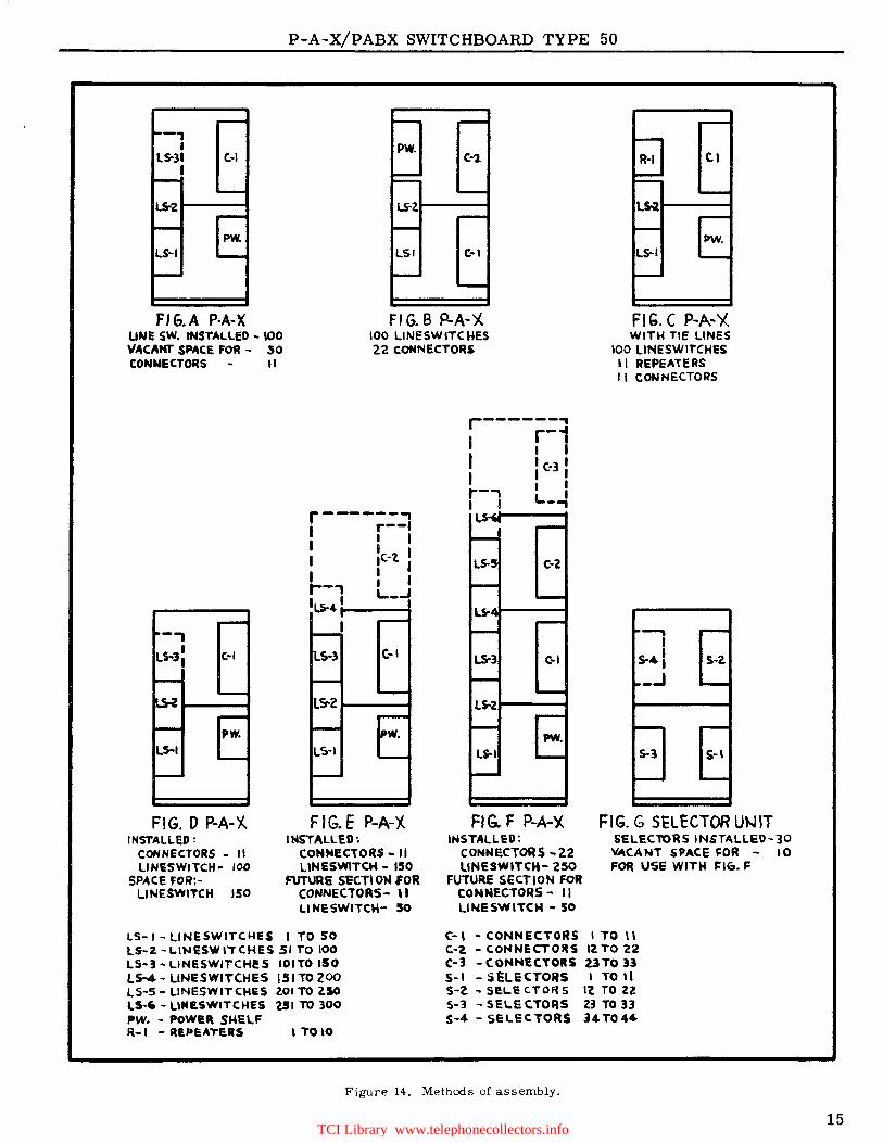
The switchboard cabinet is of metal and made sectionally. A typical installation, figure 1, cons is ts of two sections. Together (page 15 figure D) the two sections can accommodate 150 plunger lineswitches, 11 connectors, and a power shelf. The power shelf (figure 9) consists of a ringing converter, ringing interrupter, tone and charge-control relays, code-call equipment, ammeter, and voltmeter. If traffic requires more connectors, the two sections can follow the form of page 15 figure B. Page 15 figures A-G show the ease with which sectional design can be made to suit local requirements. The battery eliminator is placed adjacent to the cabinet as in figure 15.
The approximate overall dimensions of the twosection cabinet are 6' 4" wide X 2' deep X 4' 11" high. It is equipped with hinged, collapsible doors on front and rear, allowing easy access to the equipment and wiring.
The doors, as well as other parts of the cabinet can be easily removed during the time installation work is in progress, such as re-arrangement or additions to shelves and other equipment.
17. ASSOCIATED EQUIPMENT
17. 1 Protection
The majority of stations connected to a P-A-X, are located within the building where the switchboard is located, and therefore the lines to these stations would not ordinarily require
12
lightning protection. In some instances, however, a number of lines are liable to exposure to lightning or to contact with electrical power lines, and suitable protection should be provided for each exposed line. The most economical method is to interpose a protector in the line, between the exposed and unexposed portions. Should tie lines be established between a Type 50 switchboard and another private exchange switchboard either automatic or manual, the need for protection on such lines should be given due consideration.
Protectors are supplied in blocks of 10, 20 or 25 pairs per block; and may be mounted on a distributing frame of the "wall" or "floor" type.
17. 2 Terminal Equipment
The cables or interior wiring from the P-A-X telephone stations are terminated on the connector-bank terminal blocks, unless protection is used, in that event the wiring is terminated at the protectors. Inter-connections between the connector bank terminals, protector terminals (when used), and line switch terminals are established by means of flexible jumper wire or cables.
17. 3 Storage Battery or Battery Eliminator
The initial and ultimate capacity of the power supply for the Type 50 P-A-X depends upon several factors; amongst these are:
17.31 Initial and ultimate number of lines.
17. 32 The traffic to be carried by the equipment.
17.33 The number and kind of special services which are to be provided.
17.34 Local conditions, as regards to the reliability of the commercial power supply.
Therefore the power supply is to be determined for each installation in accordance with the known conditions.
17.4 Normally a battery eliminator is used; however, if the local commercial power is not dependable or if P-A-X telephone service is of extreme importance in time of commerciai power failures (e.g. power plants, hospitals) a· battery and charger should be used.
17. 5 Rectifier
When commercial 105- to 125-volt alternating current (a.c.) is available, it is standard practice to use a rectifier of the dry-plate type of sufficient capacity to charge the battery at its normal rate.
TCI Library www.telephonecollectors.info
P-A-X/PABX SWITCHBOARD TYPE 50
CALLING STATION N0.41
LINE8C.0
LINE SWITCH
,___ __ ...., RELAYS i-------<
LINE SWITCH
CONNECTOR
CALLED STATION N0.43
JTRUNKS TO CENTRAL OFFICE AND/OR TIE- LINES
--------------+- TO ANOTHER P-A-X.
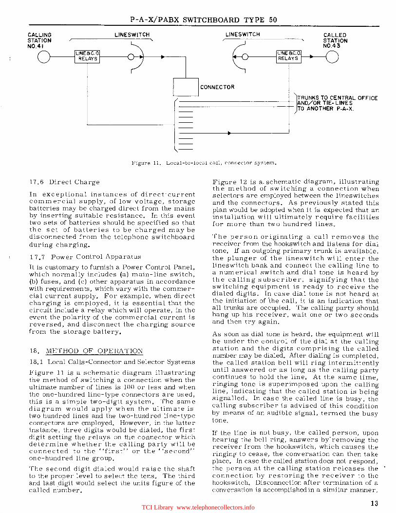
Figure 11. Local-to-local call, connector system.
17. 6 Direct Charge
In exceptional instances of direct·current commercial supply, of low voltage, storage batteries may be charged direct from the mains by inserting suitable resistance. In this event two sets of batteries should be specified so that the set of batteries to be charged may be disconnected from the telephone switchboard during charging.
17.7 Power Control Apparatus
It is customary to furnish a Power Control Panel, which normally includes (a) main-line switch, (b) fuses, and (c) other apparatus in accordance with requirements, which vary with the commercial current supply. For example, when direct charging is employed, it is essential that the circuit include a relay which will operate, in the event the polarity of the commercial current is reversed, and disconnect the charging source from the storage battery.
18. METHOD OF OPERATION
18.1 Local Calls-Connector and Selector Systems
Figure 11 is a schematic diagram illustrating the method of switching a connection when the ultimate number of lines is 100 or less and when the one-hundred line-type connectors are used, this is a simple two-digit system. The same diagram would apply when the ultimate is two hundred lines and the two-hundred line-type connectors are employed. However, in the latter instance, three digits would be dialed, the first digit setting the relays on the connector which determine whether the calling party will be connected to the·• 'first'' or the ''second" one-hundred line group.
The second digit dialed would raise the shaft to the proper level to select the tens. The third and last .digit would select the units figure of the called number.
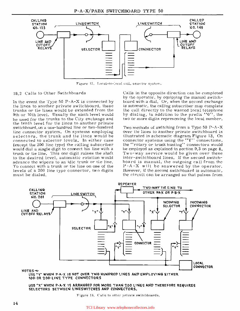
Figure 12 is a. schematic diagram, illustrating the method of switching a connection when selectors are employed between the lineswitches and the connectors. As previously stated this plan would be adopted when it is expected that an installation will ultimately require facilities for more than two hundred lines.
The person originating a call removes the receiver from the hookswitch and listens for dial tone. If an outgoing primary trunk is available, the plunger of the lineswitch will enter the lineswitch bank and connect the calling line to a numerical switch and dial tone is heard by the calling subscriber, signifying that the switching equipment is ready to receive the dialed digits. In case dial tone is not heard at the initiation of the call, it is an indication that all trunks are occupied. The calling party should hang up his receiver, wait one or two seconds and then try again.
As soon as dial tone is heard, the equipment will be under the control of the dial at the calling station and the digits comprising the called number may be dialed. After dialing is completed, the called station bell will ring intermittently until answered or as long as the calling party continues to hold the line. At the same time, ringing tone is superimposed upon the calling line, indicating that the called station is being signalled. In case the called line is busy, the calling subscriber is advised of this condition by means of an audible signal, termed the busy tone.
If the line is not busy, the called person, upon hearing the bell ring, answers by· removing the receiver from the hookswitch, which causes the ringing- to cease, the conversation can then take place. ln case the called station does not respond, the person at the calling station releases the • connection by restoring the receiver to the hookswitch. Disconnection after termination of a conversation is accomplished in a similar manner.
13 TCI Library www.telephonecollectors.info
P-A-X/PABX SWITCHBOARD TYPE 50
CAlUNG STATION tJO. 123
lHJESWITCK CALLED '3TATI0"3 ~ o. 14.9
LINE AND CUTOFF RELAVS
Figure 12. Local-to-local call, selector system.
18.2 Calls to Other Switchboards
In the event the Type 50 P-A-X is connected by tie lines to another private switchboard, these trunks or tie lines would be extended from the 9th or 10th leveL Usually the ninth level would be used for the trunks to the City exchange and the tenth level for tie lines to another private switchboard, on a one-hundred line or t\vo-hundred line connector system. On systems employing selectors, the trunk and tie lines would be connected to selector levels. In either case (except the 200 line type) the calling subscriber would dial a single digit to connect his line with a trunk or tie line. This one digit raises the shaft to the desired level, automatic rotation would advance the wipers to an idle trunk or tie line. To connect with a trunk or tie line on one of the levels of a 200 line type connector, two digits must be dialed.
CALLIN<DSTATI01'1
t-.10. 20f
WOTES'""1
"1•x•t SELECTOR LJ _
Calls in the opposite direction can be completed by the operator, by equipping the manual switchboard with a dial. Or, when the second exchange is automatic, the calling subscriber may complete the call directly to the wanted local telephone by dialing, in addition to the prefix "O", the two or more digits representing the local number.
Two methods of switching from a Type 50 P-A-X over tie lines to another private switchboard is illustrated in schematic diagram Figure 13. On connector systems using the "Y'' connections, the ''rotary or trunk hunting'' connectors would be employed as explained in section 9.3 on page 8. Two-way service would be given over these inter-switchboard lines. If the second switchboard is manual, the outgoing call from the P-A-X will be answered by the operator. However, if the second switchboard is automatic, the circuit can be arranged so that pulses from
REPEATER TWO-WAV TIE LINE TO OTHER J:tM< OR P-B-X
"v"
CONNECTOR •y• <Py''
IN COM II-JG COfllt.IECTOR
LOCAL CONNECTOR
USE"'{" WHEN l'-11.-X IS NOT OVER TWO HUNDRED llNES AllJD EMPLOYll'JG EITHER mo-OR '2.00-UNE TYPE CONNECTORS
USE"~" VJl·H:N 1'-A-~ \S ARRANGED FOR MORE THM.J -200 LINES AND THEREFORE RE~UIRES SELECTORS BETWEEllJ l1NESWITCHES ANP CONNECTORS.
Figure 13. Calls to other private switchboards.
14 TCI Library www.telephonecollectors.info
P-A-X/PABX SWITCHBOARD TYPE 50
-, I PW.
LS-31 C.·I C-1 ti I
LW Ls-2. LW
PW. PW. LS-I LSI C•1 LS--1
ff G.A P·A·X UNE SW. INSTALLED • \00 VACANT SPACE FOR • .50
Fl G. B P-A-X 100 LINESWITCHES 22 C.ONNECTORS
FIG. C P-A-Y.. WITH TIE LINES
100 l..INESWITCHt:S 11 REPEATERS CONNECTORS 1 I
-, LS.JI I
LS-I
c.-1
PW.
FIG. D P-A-)(. INSTALLED:
CONNECTORS - II LINISWITCH• 100
SPACE FOR:LINESWITCH 150
r------~ I r--1 I I I I :c-? I I I I r--, I I ILH I L..-.J
I
S-l t·I
LS-I
FIG.E P-A-X INSTALLED~
CONNECTORS - II l\NESWITCH - 150
FUTURE SliCTl ON #Oft CONNECTORS- U LINESWITCM- 50
LS- I - LINESWITCl-IES I TO SO lS·Z ·LIWESWlTCHl!S SI TO 100 LS-J•LINESWlrCHE!S IOITO 150 Ls-.4 • LINESWITCHES 151 TO ZOO LS-5- LJNESWITCHES ZOI TO 2.50 I.~ ·LINE.SWITCHES 251 TO 300 PW. - POWll\ SHELF ~-I - R&PEA,.1!.15 l TO 10
I I CON NEC TORS
C•Z
c-1 S·2.
PW. LS-I S-3
,_,
FIG. F P-A-~ FIG. G SELECTOR Ut-J1T INSTALLED:
CONNECTORS ·Z2 llNESWITCH- 250
FUTURE SECTION FOR CONNECTORS - II LINESWl'TCH - 50
SELEClORSINSTALLED-30 ~CANT SPACE J:OR - lO FOR use WITM S:IC:.. F
C-l •CONNECTORS ITO I\ C.·Z - C.ONNECTOltS 12 TO 'Z2 C-3 - CONNECTORS 2JTO 33 S· I - S ELECTOltS I TO 11 S-2. .. seLe c. TOR s I? TO l2 S·l - SEl.E C.TORS 23 TO 33 S-4 - SELECTORS J4 T044
Figure 14. Methods of assembly.
15 TCI Library www.telephonecollectors.info
P-A-X/PABX SWITCHBOARD TYPE 50
P-A-X TYPE 50 INSTALLATION DIAGRAM TYPICAL FRONT VIEW
APPROXIMATELY Ji' CLEARANCE IS REQUIREC..ABOVE CAt:UNET
CODE CALL UNIT IS SELF-CONTAINED
r ===.==. === ~~~~~~~;;
~ 2'4y,• BATTERY
ELIMINATOR
b~'ll.1= lf~'iil.ll.ifit.tif~~iU_ TERMINAL BOXES)
INDIVIDUAL LINES TO NEARBY TELEPHONES
(IF BATTERY AND CHARGER ARE USED, THEY ARE MOUNTED CONVENIENTLY NEAR THE SWITCHBOARD OR CONTAINED IN A SEPARATE CABINET)
llD VOL TS AI;.
TYPICAL TOP VIEW
~---·y ~----:-POWER-~ TO ALL ,; CODE CALL UNIT I RELAY I SIGNALS
, "" ~1f~1'N"-sc~1~h~~ED !..------~110 VOLTA.C. BOARD CABINET ~~~~~~~N~~~~~
21611 TO 3' CL.£ARANCE'' IS NEEDED, BOTH FRONT ANO BACK FOR llOORS TO OPEN DURING INSTALLATION ' AND OCCASIONAL /
', '·
LINES AND CABLES TO TELEPHONES
2'
' '
ALL ELEMENTS ARE ALWAYS PLACED FOR MAXIMUM ECONOMY OF SPACE
MAXIMUM WIRING ECONOMY
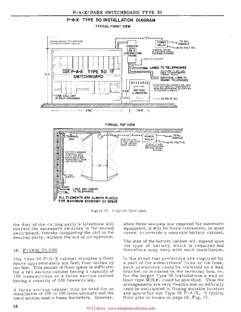
Figure 15. A typical floor plan.
the dial of the calling party's telephone will operate the necessary switches in the second switchboard, thereby completing the call to the desired party, without the aid of an operator.
19. FLOOR PLANS
The Type 50 P-A-X cabinet occupies a floor space approximately six feet, four inches by two feet. This amount of floor space is sufficient for a two section cabinet having a capacity of 150 lineswitch~s or a three section cabinet having a capacity of 250 lineswitches.
A three section cabinet may be used for an installation of 100 to 150 lines ultimate and the lower section used to house the battery. However,
16
when three sections are required for automatic equipment, it will be more convenient, in most cases, to provide a separate battery cabinet.
Ths size of the battery cabinet will depend upon the type of battery which is required and therefore may vary with each installation.
In the event that protectors are required for a part of the subscribers' lines or tie lines, such protectors could be installed on a wall bracket or mounted in the terminal box, or, for the larger Type 50 installations a wall or floor type M.D.F. could be specified. Thus the arrangements are very flexible and no difficulty need be anticipated in finding suitable location and· space for the Type 50 P-A-X. A typical floor plan is shown on page 16, Fig. 15.
TCI Library www.telephonecollectors.info
P-A-X/PABX SWITCHBOARD TYPE 50
WEIGHTS OF EQUIPMENT - P-A-X/PABX SWITCHBOARD TYPE 50
ITEM
1. Iron frame, three sections high, one sect.ion wide, including one lineswitch shelf with 50 lineswitches and one master switch, one connector shelf with 11 connector banks (300 point) and 7 connector switches (100 line type) and, 1 light duty power shelf with power panel, vibrating ringing machine, ringing
POUNDS
interrupter, charge control relays and alarm signal relays • 960
For the Above:
1.1 Miscellaneous switchboard ironwork, cable runway, switchboard cable and wire, and miscellaneous installing materials for Item 1 • 550
1.2 Three section cover for Item 1, including doors 585
1.3 To increase Item 1 to accommodate 100 subscribers' lines, add the following Items A and B:
A. One primary lineswitch shelf with 50 lineswitches and 50 lineswitch banks, including. mounting frame, connecting link and miscellaneous materials 360
B. One or more, one-hundred line type connector switches, each 40
NOTE: Only 4 connectors may be added to Item 1. If more are required, then also add a connector shelf and set of banks. See Item 2.
2. Connector shelf including 11 connector banks (300 point), terminal block and shelf supervisory equipment . 190
3. Selector shelf including 10 selector banks (300 point), 10 selector switches, terminal block and shelf supervisory equipment 250
4. To increase Item 1 from three sections high to four sections high, add end frame for one section including miscellaneous ironwork and a one section cover with doors 370
5. Battery cabinet for a storage battery of 48 volts and 100 AH (consisting of 8 - 3 cell units) 295
6. (a) Storage battery, of 48 volts and 120 AH capacity, consisting of 24 individual cells 1350
(b) Storage battery, of 48 volts and 200 AH capacity, consisting of 24 individual cells 1800
7. Battery eliminator, 6 ampere capacity 170
8. Charger (fully automatic rectifier - available in three capacities - 3, 6, and 12 amperes filtered direct current) - net weight 125, 200, and 310 lbs. respectively.
NOTES:
A. The figures in pounds, shown above, are the weight of the equipment and materials packed for domestic shipping by railway or motor transport, in the United States and Canada and are classed as domestic weight.
B. All figures are approximate and for estimating purposes only.
C. Special packing is required for shipping overseas and in addition to net weight, the transportation companies require the gross weight and the space in cubic feet, the latter being required in determining the costs of shipping by steamer, these may be estimated as follows:
(1) Domestic weight in pounds multiplied by 1.5 equals gross weight.
(2) Domestic weight in pounds multiplied by the factor .061 equals the cubic feet space which will be occupied by the equipment when packed for shipment by steamer.
The factors mentioned in C-1 and C-2 cannot be used for individual shipments of storage batteries.
17 TCI Library www.telephonecollectors.info

P-A-X/PABX SWITCHBOARD TYPE 50
Figure 16. Type 80 Monophone.
This desk Monophone is one of the newest and most popular types of telephones offered for P-A-X service - a strikingly modern, yet dignified, design suitable for use in the finest office. It is of the "self-contained" type, including the bell signal, and therefore does not require a separate bell box. It is pleasant to use, because of the smooth-running "silent" dial and the lightweight handset - which is non-tiring
even in extended conversations. Two-toned gongs provide a pleasing and effective call signal. Voice transmission is clear, crisp, and lifelike.
A six-foot line cord and a terminal block are provided for connection to P-A-X line. Handset may have an Extensicord or a Koiled Kord, if specified.
DIMENSIONS - Beight, 4~" (11.1 cm); width, 5!" (13.3 cm); depth, 9t" (24.2 cm).
WEIGHTS - Net weight, 6~ lb. (3 kg); shipping weight, 9 lb. (4 kg).
18
(
(
(
TCI Library www.telephonecollectors.info
(
(
P-A-X/PABX SWITCHBOARD TYPE 50
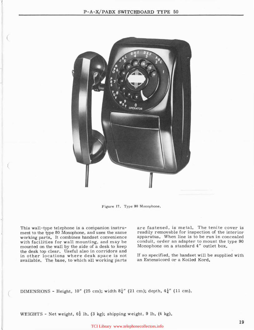
Figure 17. Type 90 M onophone.
This wall-type telephone is a companion instrument to the type 80 Monophone, and uses the same working parts. It combines handset convenience with facilities for wall mounting, and may be mounted on the wall by the side of a desk to keep the desk top clear. Useful also in corridors a nd in other locations where desk space is not available. The base, to which all working parts
are fastened, is metal. The tenite cover is readily removable for inspection of the interior apparatus. When line is to be run in concealed conduit, order a n adapter to mount the type 90 Monophone on a standard 4" outlet box.
If so specified, the handset will be supplied with an Extensicord or a Koiled Kord.
( DIMENSIONS - Height, 10" (25 c m); width Bi" (21 cm); depth, 4i" (11 cm).
WEIGHTS - Ne t weight, 6t lb. (3 kg); shipping weight, 9 lb. (4 kg).
19 TCI Library www.telephonecollectors.info

,
Revised May 1956 Printed in U.S.A. by Brookes & Sons Company 1000 2-58
TCI Library www.telephonecollectors.info

TCI Library www.telephonecollectors.info
\
AUTOMATIC .. ELECTRIC
ORIGINATORS OF THE DIAL TELEPHONE
Makers of Telephone, Signaling, and Communication Apparatus •.. Electrical Engineers, Designers, and Consultants
Factory and General Offices: Northlake, Illinois, U.S.A .
• ASSOCIATED RESEARCH AND MANUFACTURING COMPANIES
General Telephone. Laboratories, Incorporated
Automatic Electric (Canada) Limited
Automatique Electrique, S.A. -
Automatic Electric, S. A. T. A. P.
•
Northlake, Illinois, U.S. A.
Brockville, Ontario, Canada
Antwerp, Belgium
- - - Milan, Italy
DISTRIBUTOR IN U.S. AND POSSESSIONS
AUTOMATIC ELECTRIC SALES CORPORATION Northlake, Illinois, U.S.A.
Sales Offices in All Principal Cities
• GENERAL EXPORT DISTRIBUTOR
AUTOMATIC ELECTRIC INTERNATIONAL JNCORPORATED
Northlake, Illinois, U.S. A .
• REGIONAL DISTRIBUTING COMPANIES AND REPRESENTATIVES
ARGENTINA, URUGUAY, PARAGUAY, COLOMBIA CHILE, AND BOLIVIA Automatic Electric de Colombia, S.A.
D. C. Clegg Apartado Aereo 3968 Sala 61 Bogota, Colombia Rua Conselheiro Crispiniano No. 69 Sao Paulo, Brazil
AUSTRALIA. Automatic Electric Telephones Limited 86 Holdsworth Street, W oollahra Sydney, Australia
BELGIUM AND LUXEMBOURG Automatique Electrique, S. A. 22 Rue du Verger Antwerp, Belgium
BRAZIL Automatic Electric do Brasil, S. A. Sala 61 Rua Conselheiro Crispiniano No. 69 Sao Paulo, Brazil
CANADA Automatic Electric Sales (Canada) Limited 185 Bartley Drive Toronto 16, Ontario, Canada
CENTRAL AMERICA L. Pitigliani Apartado Postal 21327 Mexico 7, D. F., Mexico
VENEZUELA
EUROPE. NORTH AFRICA, AND NEAR EAST
Automatic Electric International, Incorporated
P. 0. Box 15 Geneva Montbrillant Geneva, Switzerland
ITALY Automatic Electric S;A. T.A.P. V-ia Bernina 12 Milan, Italy
MEXICO Automatic Electric de Mexico, S.A. Apartado Postal 21327 Mexico 7, D.F., Mexico
NETHERLANDS Automatique Electrique, S.A. Huygenstraat 6 's-Gravenhage, Netherlands
PERU AND ECUADOR J. P. Maclaren Apartado Aereo 3968 Bogota, Colombia
Automatic Electric De Venezuela, Compaiiia Anonima Apartado 6362, Est. Caracas, Venezuela
Other Sales Representatives and Agents Throughout the World
Automatic Electric Company ... A member of the General Telephone System
,, I
)> I
>< ~ ,, )> g:,
><
TCI Library www.telephonecollectors.info