Upload others
View 3
Download 0
Embed Size (px) 344 x 292 429 x 357 514 x 422 599 x 487
Citation preview
One component phase diagram - University of California ...maecourses.ucsd.edu/~jmckittr/mae20-wi11/C9-Phase diagrams.pdf · 1 1 Chapter 9: Phase diagrams One component phase diagram
Component Diagram Mod
Clickermatic Client Component-Level Design. Client Class Diagram ControllerTimerUserInterfaceQuestionDefaultProtocolClientConnectionManagerNetworkInterfaceQuestionRecordHistorian
Residential Heating and Cooling Loads Component …simulationresearch.lbl.gov/dirpubs/44636.pdfRESIDENTIAL HEATING AND COOLING LOADS COMPONENT ANALYSIS ... (heat loss for heating,
Service Manual Micro Component Systemcncms.com.au/SANYO-SMs/Consumer-Electronics/Audio System...Schematic Diagram (USB/SD) .....19 Wiring Diagram (CD).....20 Wiring Diagram (CONTROL)
Activity, State, Component, Deployment Diagram · 6 – Activity, State, Component, Deployment Diagram Ký hiệu 7 Biểu đồ hoạt động chỉ mô tả điều gì xảy ra
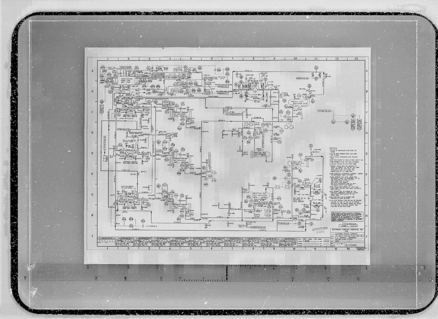
Drawing 5379-376LR, Sheet 4, 'Component Cooling Water
Crankshaft Valve Lub Cooling & FO diagram katup
-Component Diagram -Deployment Diagramsiam2dev.net/E_Learning/OOAD/Lec11_OOAD_Application... · 2018. 2. 10. · Deployment Diagramซึ่ง Deployment Diagram เป น Diagram
Continuous Cooling Transforming Diagram
Chủ đề 2: UML - monhoc.weebly.com · •Biểu đồ gói (Package diagram) •Biểu đồ thành phần (Component diagram) •Biểu đồ triển khai (Deployment diagram)
TIME-TEMPERATURE- TRANSFORMATION DIAGRAM...TTT Diagram On the other hand, TTT diagram is a more practical diagram. It shows what structures can be expected after various rates of cooling
BasicRefrigerationSystem 4 Component Flow Diagram
UML Primer - OoCities · UML diagrams Types of UML Diagrams Structural Diagrams Class Diagram, Object Diagram, Component Diagram, and Deployment Diagram. Behavior Diagrams Use Case
Experiment - Phase Diagram -Three Component Liquid System
P & I DIAGRAM COMPONENT COOLING WATER SYSTEM.Sheet 2 …
COMPONENT DIAGRAM in UML 2.0 Veronica Carrega
Android Application Designstaff.ustc.edu.cn/~waterzhj/files/appdesign/Session 2.pdf · 2017-09-09 · Class Diagram, Object Diagram, Component Diagram, Composite Structure Diagram,
Technical Specification - Component Cooling Water System.CC System B 3.7.7 B 3.7 PLANT SYSTEMS B 3.7.7 Component Cooling Water (CC) System BASES BACKGROUND The CC System provides a
Ten64 Component Placement Diagram (Top Side)
Wiring Diagram - Danfosspfheating.danfoss.com/PCMPDF/X021412_Df_DHP-R_wiring_VWIFB102… · 307 Distribution circulation pump ... 460 HPC-CM Cooling module ... Wiring Diagram DHP-R
Phase equilibrium Plan 1.Phase equilibrium. Gibb’s phase rule. 2.Diagram of the state for a one component system 2.Diagram of the state for a one component
Thermal analysis of cooling curves for phase diagram
Z-Retinal, shown in the diagram, is a component in vitamin
District Cooling, Key Component in Sustainable District
(a) Component block diagram of a room temperature control
CFD Modeling of High Heat Flux Component Cooling FNST …info.ornl.gov/events/fest_seminar/Shared Documents/2011_08_01... · CFD Modeling of High Heat Flux Component Cooling – FNST
Table 9.2.2-5—Component Cooling Water System - Failure ... · Table 9.2.2-5—Component Cooling Water System - Failure Modes and Effects Analysis Sheet 1 of 25 Component Name Identifier
Papyrus User Guide - Eclipsepedia - unipr.it · · 2014-09-01Initialize Sequence Diagram Initialize Deployment Diagram ... Structures Diagram Initialize Component Diagram Initialize
Architecture Overview Diagram & Component Model · High level design focuses on component identification Detailed design deals with component specification Development deals with