Embed Size (px)
Citation preview

P/N 1010918 Rev. E 03/13
MT-12owner’s manual
muffin toaster
Manufacturing Numbers:9200139, 9200146, 9200148
www.ajantunes.com
Partial Load
READY

2 P/N 1010918 Rev. E 03/13
SERVICE/TECHNICAL ASSISTANCEIf you experience any problems with the installation or operation of your unit, contact your local Roundup Authorized Service Agency.
Fill in the information below and have it handy when calling your Authorized Service Agency for assistance. The serial number is on the specification plate located on the rear
of the unit.
Use only genuine Roundup replacement parts in this unit. Use of replacement parts other than those supplied by the manufacturer will void the warranty. Your Authorized Service Agency has been factory trained and has a complete supply of parts for this toaster.
Visit www. ajantunes.com or contact the fac-tory at 1-630-784-1000 to locate your nearest Authorized Service Agency.
Refer to the service agency directory packaged with your manual and fill in the information below.
GENERALThe Muffin Toaster Model MT-12 is designed to toast 6 full English muffins (12 halves) at one time. A temperature sensing solid state control measures the internal temperature of the toaster and adjusts the toasting time automatically to toast muffins faster during heavier use. The toaster signals the operator with an audible beep and a ready light when muffins are ready.
The toaster is capable of producing up to 324 muffins per hour. 6 muffin halves or less is a partial load and 7 - 12 muffin halves is a full load.
To conserve energy, when the toasting cham-ber is empty, the toaster idles at 600 watts. This represents a 75% reduction in opera-tional power consumption.
This manual provides the safety, installation, and operating procedures for the unit. We recommend that all information contained in this manual be read prior to installation and operation.
This unit is manufactured from the finest materials available and is assembled to Roundup’s strict quality standards. It has been tested at the factory to ensure depend-able trouble-free operation.
WARRANTY INFORMATIONPlease read the full text of the Limited Warranty in this manual.
If the unit arrives damaged, contact the car-rier immediately and file a damage claim with them. Save all packing materials when filing a claim. Freight damage claims are the responsibility of the purchaser and are not covered under warranty.
The warranty does not extend to:
• Damages caused in shipment or dam-age as result of improper use.
• Installation of electrical service.
• Normal maintenance as outlined in this manual.
• Malfunction resulting from improper maintenance.
• Damage caused by abuse or careless handling.
• Damage from moisture into electrical components.
• Damage from tampering with, removal of, or changing any preset control or safety device.
General .................................................. 2Warranty Information ............................. 2Service/Technical Assistance ................... 2Important Safety Information ................. 3Warnings ................................................ 3Specifications ......................................... 4Installation ............................................. 5Operation ............................................... 6Hi-Limit Reset Button ............................. 7Maintenance Schedule ........................... 7Function of Diagnostic LEDs ................... 7Diagnostic Flow Chart ............................ 8Troubleshooting...................................... 9Wiring Diagram ...................................... 11Replacement Parts .................................. 12Notes ...................................................... 14Limited Warranty .................................... 16
Table of Contents
Purchased From
Date of Purchase
Authorized Service Agency
Model Number
Name
Serial Number
Phone Number
Manufacturing Number
Address
IMPORTANTA.J. Antunes & Co. reserves the right to change specifications and product design without notice. Such revisions do not entitle the buyer to corresponding changes, improvements, additions or replacements for previously purchased equipment.
IMPORTANTKeep these instructions for future ref-erence. If the unit changes ownership, be sure this manual accompanies the equipment.

3P/N 1010918 Rev. E 03/13
IMPORTANT SAFETY INFORMATIONUse the following guidelines for safe opera-tion of the unit.
• Read all instructions before using equipment.
• For your safety, the equipment is fur-nished with a properly grounded cord connector. Do not attempt to defeat the grounded connector.
• Install or locate the equipment only for its intended use as described in this manual. Do not use corrosive chemicals in this equipment.
• Do not operate this equipment if it has a damaged cord or plug, if it is not working properly, or if it has been damaged or dropped.
• This equipment should be serviced by qualified personnel only. Contact the nearest Roundup authorized service facility for adjustment or repair.
• Do not block or cover any openings on the unit.
• Do not immerse cord or plug in water.
• Keep cord away from heated surfaces.
• Do not allow cord to hang over edge of table or counter.
• Turn the unit off, unplug the power cord, and allow unit to cool down before performing any service or maintenance on the unit.
• The procedures in this manual may include the use of chemical prod-ucts. These chemical products will be highlighted with bold face letters followed by the abbreviated HCS (Hazard Communication Standard). See Hazard Communication Standard manual for the appropriated Material Safety Data Sheets (MSDS).
• The equipment should be grounded according to local electrical codes to prevent the possibility of electrical shock. It requires a grounded recep-tacle with separate electrical lines, protected by fuses or circuit breaker of the proper rating.
• Bread may burn. Therefore toasters must not be used near or below cur-tains or other combustible walls and materials. Failure to maintain safe operating distances may cause discol-oration or combustion.
• Do not clean this appliance with a water jet.
WARNINGSBe advised of the following warnings when operating and performing maintenance on this unit.
• If the supply cord is damaged, it must be replaced by the manufacturer or its service agent or a similarly qualified person in order to avoid a hazard.
• Do not modify the power supply cord plug. if it does not fit the outlet, have a proper outlet installed by a qualified electrician.
• Do not use an extension cord with this appliance.
• Check with a qualified electrician if you are in doubt as to whether the appliance is properly grounded.
• If a chemical cleaner is used, be sure it is safe to use on cast aluminum. Observe all precautions and warnings on product label.
• Hot toasting surfaces will be exposed during maintenance steps. Use extreme care to avoid personal injury.
• Inspection, testing, and repair of elec-trical equipment should only be per-formed by qualified service personnel.
• Chlorides or phosphates in cleans-ing agents (e.g. bleach, sanitizers, degreasers or detergents) could cause permanent damage to stainless steel equipment. The damage is usually in the form of discoloration, dulling of metal surface finish, pits, voids, holes, or cracks. This damage is permanent and not covered by warranty. The following tips are recommended for maintenance of your stainless steel equipment:
• Always use soft, damp cloth for cleaning, rinse with clear water and wipe dry. When required, always rub in direction of metal polish lines.
• Stains and spots should be sponged using a vinegar solution.
• Finger marks and smears should be rubbed off using soap and water.
• Check with a qualified electrician if you are in doubt as to whether the appliance is properly grounded.
• Do not use an extension cord with this appliance.
• Electrical ground is required on this appliance.

4 P/N 1010918 Rev. E 03/13
SPECIFICATIONS
Model & Mfg. No.
Volts Watts Amps HertzPlug
DescriptionConfiguration
MT-12 9200139
(Australia)
220-240
3400 15.4 - 14.2 50/60
AS3112 Australian
Plug 20 Amp., 250 VAC.
MT-12 9200146
(US & Canada)
208 3400 16.3 50/60
Straight Twist Lock
L6-20P, 20 Amp., 250 VAC
R
R
30A. 250V.
MT-12 9200148 (Europe)
220-240
3400 15.5 - 14.2 50/60
Pin & Sleeve IEC-309 16 Amp., 230 VAC (Europe)
A
C
B
Model & Mfg. No.
Width (A)
Depth(B)
Height (C)
MT-12 9200139 9200146 9200148
15 5/8” (397 mm)
26 5/8” (676 mm)
8 1/8” (207 mm)
Model & Mfg. No.
Agency Approvals
MT-12 9200139 9200146 9200148
CTI SL
USE D
AS
DL I S T E CM
OI NNITA T
Testing & Certification
ITS
geprufteSicherheit

5P/N 1010918 Rev. E 03/13
INSTALLATION1. Remove unit and all packing materials
from shipping carton.
2. Open the large box. It should contain the following items:
• Muffin Toaster with Crumb Tray
• Information Packet
3. Remove information packet.
4. Remove all packing materials and pro-tective coverings from the unit.
NOTE: If any parts are missing or dam-aged, contact Antunes IMMEDIATELY at 1-630-784-1000 or in the U.S. or Canada, 1-800-253-2991 toll free.
5. Clean the toaster with a damp cloth. Remove and clean the Crumb Tray and Removable Plate (refer to the Maintenance secton of this manual).
When placing the toaster into service, pay attention to the following guidelines.
• Make sure the unit’s power On/Off switch is off and the toaster is at room temperature before plugging in the power cord.
• Do not block or cover any openings on the unit.
• Do not immerse the power cord or plug in water.
• Keep the power cord away from heated surfaces.
• Do not allow the power cord to hang over edge of table or counter.
Plug the power cord into the appropriate power outlet. Refer to the specification plate for the proper voltage.
Figure 1. Muffin Toaster MT-12
Partial Load
READY
Crumb Tray
Front Door Control Knob
Indicator Light (Amber)
Indicator Light (Green)Removable Plate
Partial Load Timer Control Knob

6 P/N 1010918 Rev. E 03/13
Partial Load
READY
Turn Power Switch ON
(Back of Unit)
The unit beeps twice and both lights blink twice.
Allow the unit to warm up for 30 minutes.
A
B
1
FULL LOAD = 7 - 12 muffin halves
PARTIAL LOAD = 1 - 6muffin halves
2
Partial Load
READY
Press the Partial Load button ONLY when toasting
a partial load of product.
3
Partial Load
READY
Push the Front Door Control Knob IN
to UNLOCK and open the Front Door.
Next, slide the loaded Spatula into the unit.
A
B
4
5
NOTE: When the Amber light is on, a Partial Load Cycle is selected. When this light is off, a Full Load Cycle is selected.
NOTE: Always use a Spatula to insert and remove product from the unit. This is the only approved method for loading and unloading product into the toaster.
Partial Load
READY
Pull the Front Door Control Knob OUT to close and LOCK
the Front Door.
Next, pull out the Spatula. The locked door keeps the product inside the toaster.
A
B
Partial Load
READY
TOASTING TIMES: Full Load = 90 - 130 seconds
Partial Load = 85 - 125 seconds
6
NOTE: The indicator lights blinks and the Audio Signal beeps when the toast cycle completes.
Partial Load
READY
Carefully insert the Spatula into the unit. This transfers thethe product onto the spatula.
7
The Crumb Tray and Removable Plate will be very hot when the unit is in opera-tion. Do NOT use the Crumb Tray and Removable Plate as a means to load/unload product from the unit.
Do NOT toast product with the Spatula inserted in the toaster.
NOTE: If the self-test fails, a series of beeps will sound (see the Diagnostic Flow Chart).
Partial Load
READY
Remove the Spatula out of the unit carefully.
B
Push the Front Door Control Knob IN
to UNLOCK and open the Front Door.
A
8
9
Remove product from the spatula. The unit is ready for another cycle.
OPERATION

7P/N 1010918 Rev. E 03/13
FUNCTION OF DIAGNOSTIC LEDSThis section describes the Diagnostic LEDs and their functions. The Diagnostic LEDs (Figure 4) are found at the back of the unit.
1 Full Load Switch Light - ON when the Full Load Switch is closed.
2 Thermocouple Fault - ON when the
thermocouple is disconnected or damaged. The toaster will not heat.
3 Solid State Relay On - ON when
power is sent to the Solid State Relay. This LED pulses rapidly during opera-tion.
4 Ready Light - ON when power is sent
to the Ready Light.
5 Partial Load Switch - ON when the Partial Load Switch is closed.
6 Audio Signal - ON when power is sent to the Audio Signal.
7 Partial Load Light - ON when power is sent to the Partial Load Light.
HI-LIMIT RESET BUTTONA hi-limit thermostat will turn off electrical power to the heater and control circuits if the unit overheats. To reset the thermostat, allow sufficient time (about 45 minutes) for the unit to cool down, remove the cap and press the red reset button located on the side of the unit (Figure 2).
If the unit requires continuous resetting, con-tact your Authorized Service Agency.
Figure 2. Hi-Limit Reset Button
Partial Load
READY
Hi-Limit Reset Button
MAINTENANCE SCHEDULEDAILY – CLEAN CRUMB TRAY
1. Turn the Rocker Switch (power on/off) to OFF and unplug the power cord.
2. Allow the toaster and plate to cool sufficiently to handle.
3. From the front of the toaster, raise the Crumb Tray, and remove it from the unit (Figure 1).
4. Lift the Removable Plate from the Crumb Tray (Figure 1).
5. With a clean, damp cloth, wash the top surface of the Removable Plate.
6. Inspect the Removable Plate for exces-sive carbon build-up (use coloration of the bottom of the plate for reference). If there is only a slight carbon build-up, proceed to step 8.
7. If excessive build-up of carbon exists, remove with a griddle cloth.
8. Wipe the Removable Plate clean with a paper towel dampened with sanitiz-ing solution.
9. Reinstall the Removable Plate into the Crumb Tray, reinstall the Crumb Tray into the toaster, and plug the power cord into the appropriate power outlet.
Partial Load Temp. Timer Adjustment
Full Load Temp. Timer Adjustment
Figure 3. Timer Adjustments
Figure 4. Diagnostic LEDs
MONTHLY – CHECK CALIBRATION
NOTE: You will need a stopwatch
1. Turn the Rocker Switch (power on/off) to ON and allow the unit to preheat for approximately 30 minutes.
2. Close the front door and wait for the Audio Signal to beep. When the Audio Signal beeps, open the Front Door, then close it again. When the Audio Signal beeps a second time, open the Front Door.
3. Load 12 muffin halves into the toaster, close the Front Door, and start and start the stopwatch.
4. Check the time on the stopwatch when the Audio Signal beeps.
NOTE: The Audio Signal should beep and the Ready light should come on within 90 to 130 seconds.
5. Open the Front Door to stop the Audio Signal and to turn off the Ready light.
6. Remove muffins and reload with 6 muffin halves.
7. Close the Front Door, press and release the Partial Load Control Knob on the right front of the toaster until the Amber light is lit (Figure 1). Start the stopwatch.
8. Check the time on the stopwatch when the Audio Signal beeps.
NOTE: The Audio Signal should beep and the Ready Light should come on within 85 to 125 seconds.
9. Open the Front Door to stop the Audio Signal and to turn off the Ready light.
10. If the times are correct, calibration is complete. If the times are not correct, adjust the timers located at the rear of the toaster (Figure 3).
Rear Panel Diagnostic LEDs
1 2 3 4
5 6 7

8 P/N 1010918 Rev. E 03/13
DIAGNOSTIC FLOW CHART
Turn toaster on, toaster performs self-test
Toaster Passes Self-test
Both indicator lights flash and an Audio Signal beeps twice to indicate success-
ful self-test
Heats to more than 105°F (65°C) but less than 750°F (400°C) in 30
minutes
BEEP CODES2 Beeps = Voltage too low3 Beeps = Toaster temperature more than 750°F
(400°C) after 30 minutes4 Beeps = Toaster temperature less than 150°F (65°C)
after 30 minutes5 Beeps = Thermocouple disconnected or brokenNOTE: All beep codes are followed by a 2 second pause, then repeated.
IMPORTANT Beep Codes
(errors) can occur any time during operation.
Less than 150° F (65°C) (Control turns solid state relay off). Audio
signal beeps 4 times, waits 2 seconds, beeps 4 times, waits 2
seconds, and continues until unit is turned off
More than 750°F (400° C) (con-trol turns solid state relay off)
Audio signal beeps 3 times, waits 2 seconds, beeps 3 times, waits 2 seconds and continues until unit
is turned off
Refer to Troubleshooting
Yes
Yes
Yes
No
No No
Heats to more than 105°F (65°C) but less than 750°F (400°C) in 30
minutes
Yes
Door is opened during cook cycle - Audio Signal beeps once every
second door is openNo
Door is open for more than 8 consecutive seconds during cook cycle - Audio Signal beeps very
rapidly 15 times - cook cycle is automatically cancelled.
No
Yes Yes
Toaster times-out for:
Partial Load (85-125 sec) or Full load (90-130 sec.)
Unit beeps 2 times per second until front door is opened. NOTE: Push partial load control knob to turn off partial load light.
Product is too lightNo
Product is too darkNo
Refer to Troubleshooting
Yes
Product toasted properly
Yes

9P/N 1010918 Rev. E 03/13
TROUBLESHOOTING
Problem Possible Cause Corrective Action
Muffins too light or too dark at Audio Signal.
Using refrigerated or frozen muffins. Muffins must be at room temperature before toast-ing. Allow a two day old rotation when using fresh muffins.
Incorrect setting or regional preference dictates an adjustments of the timer. Approximate times are: Partial Load - 85-125 seconds Full Load - 90-130 seconds
Adjust full or partial load timers as needed. Refer to the Maintenance section of this manual.
Toaster does not operate properly when it is initially installed.
Toaster selected/shipped is not for the electrical ser-vice as this location.
Check toaster identification plate and refer to the Electrical Specifications of this Manual.
Toaster does not operate after the replacement of a Control Board.
One or more electrical service dip switches are improperly set for the locations electrical service.
Refer to the Dip Switch setting instructions provided in this manual.
Toaster will not operate (no heat and no fan operation) and Rocker Switch not lit.
Rocker Switch (Power On/Off) not On Confirm that the Rocker Switch is ON.
No Power. Circuit Breaker is off or tripped. Reset Circuit Breaker. Contact your maintenance person or Authorized Service Agency if it trips again.
Rocker Switch is inoperable. Replace Rocker Switch.
Poor plug to receptacle connection. Lock plug into receptacle.
Damaged or defective power cord. Inspect power cord, replace if needed.
Damaged or defective plug, and/or pins. Inspect plug and pins. Replace if needed.
Damaged or defective receptacle. Inspect receptacle. Call your electrician.
Loose electrical connection. Contact your maintenance person or Authorized Service Agency for service.
Toaster not heating (but fan is work-ing.)
Hi-Limit control is tripped or defective. Turn toaster off for 30 minutes and then reset. If the Hi-Limit control trips repeatedly, contact your maintenance person or Authorized Service Agency.
Loose/defective electrical connections. Contact your maintenance person or Authorized Service Agency.Heating element/coil is broken/open.
Solid State Heater Relay is defective.
Control Board is defective.
Fan not running but toaster is heating. Fan is dirty or defective. Clean or replace defective fan.
No Audio Signal, but Ready Light works.
Defective Audio Signal. If Audio Diagnostic LED is on but there is no Audio Signal, replace the Audio Signal.
No Ready Light but Audio Signal works.
Defective Ready Light. If Ready Light Diagnostic LED is on, but the ready light is not, replace the ready light.
No Audio Signal or Ready light on either Full or Partial Load cycles.
Control Board is Defective. Replace the Control Board.
Front Door will not open or close properly.
Door Push Rod is Damaged. Remove left cover and check Door Push rod for free movement of door. Straighten or replace rod as required.
Have your maintenance person or Authorized Service Agency straighten or replace the Door Push Rod as required.
Heating element/coil is on continu-ously
Defective Solid State Relay. Contact your maintenance person or your Authorized Service Agency.Defective Control board.
Only Half the element coil is working Loose/defective electrical wiring connection. Check wiring connections at element/coil
Heating element/coil is broken/open Replace the heating element/coil.

10 P/N 1010918 Rev. E 03/13
Dip Switch Settings
Check your Control Board assembly to insure the Dip Switch settings are correct.
NOTE: Refer to the table below for a list-ing of Manufacturing numbers that use the 220 or 200 setting.
DO NOT USE HIGH SETTING.
Mfg. No. 200 or 220? LO or High?
9200139 220 LO
9200146 200 LO
9200148 220 LO
MADE IN U.S.A.ANTUNES CONTROLS
SFT00-
0216-B
1 YELLOWRED
1 2
PARTIALDS1
- +
LED
DONE
SWPARTIALBUZZER
ONSSR THERM.
FAULT. SWFULL
PARTIAL
FULL
200HIGHBD
AC
LOW220
+-DS1
C35
C31
J3
J2
C7
C22
C4
C12
C8
C18
C2
C1
C6
C5
C27
C15
C19
C11
C23
C28
C21
C30C24
C33
C29
C34
C26
C16
C20
C32
C25
C17
C9
C13
C3
C14
C10
CRY
1
CR8
CR10
CR9
BR2 BR1
L2
L6L5
L3
U5
L4L1
CR13 CR14 CR15 CR16
CR17
CR18 CR19
U2
U4
U3
U1
R27
R29
R46
R41
R51
R31
R20
R43
R40
R44
R38
R36
R47
R49
R42
R52
R50
R39
R14
R37
R24
R23
R10
R48
R54
R53
R13
R4
R34
R7
R21
R5R2
R18
R11
R8
R15
R33
R22
R45
R12
R32
R9R6R3
R17
R35
R30
14
32
P1
1
P2
1
P4
U6
Q3
Q2
Q1
Q4
VAR1
VAR2
VRL1
P3
123
R16
R1
123
LOW HIGH200220
A BC D
Control Board

11P/N 1010918 Rev. E 03/13
WIRING DIAGRAM

12 P/N 1010918 Rev. E 03/13
Partial Load
1
3
5
6
789
10
11
12
13
14
15
28
2830
31
3233
56
40
40
46
46
H
50
5050
5050
50
52
53
View A-Next Page
57
37
75
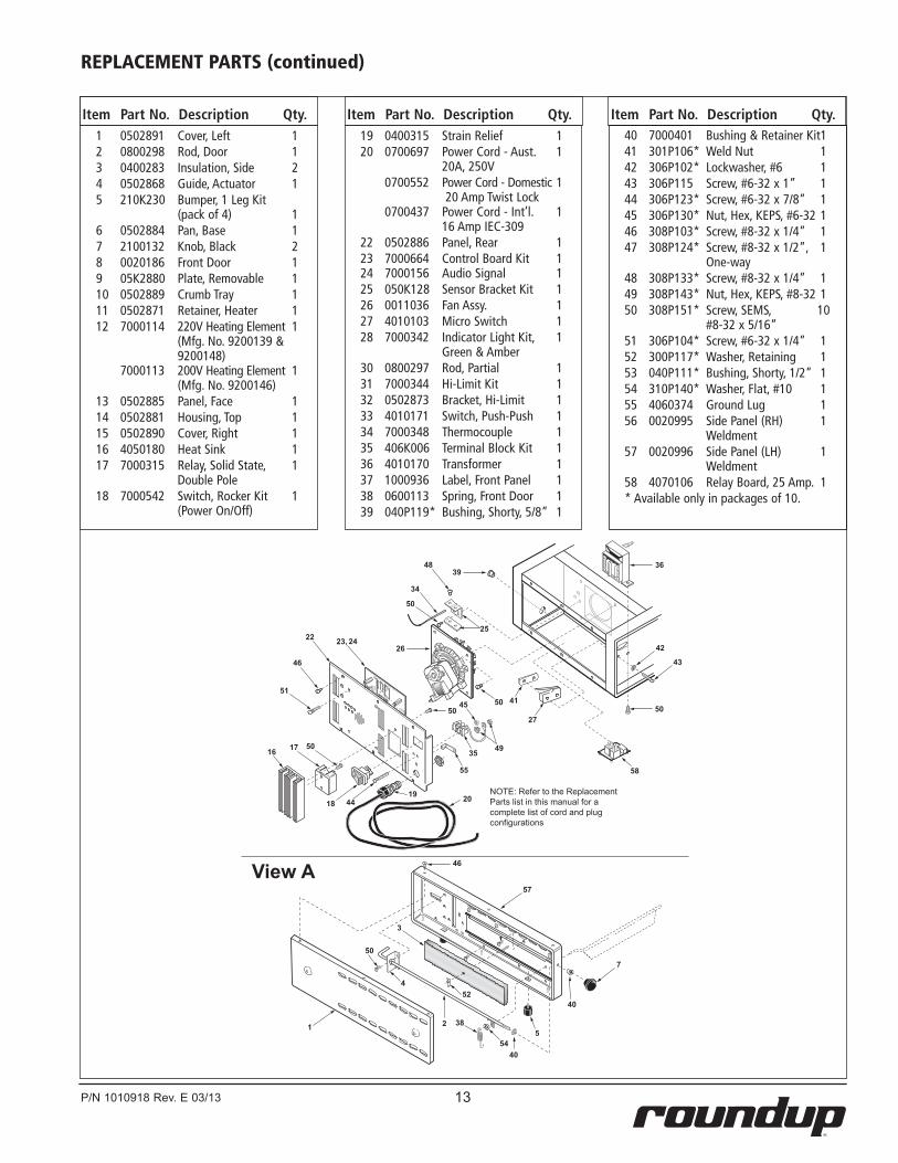
1 0502891 Cover, Left 12 0800298 Rod, Door 13 0400283 Insulation, Side 24 0502868 Guide, Actuator 15 210K230 Bumper, 1 Leg Kit (pack of 4) 16 0502884 Pan, Base 17 2100132 Knob, Black 28 0020186 Front Door 19 05K2880 Plate, Removable 110 0502889 Crumb Tray 111 0502871 Retainer, Heater 112 7000114 220V Heating Element 1 (Mfg. No. 9200139 & 9200148) 7000113 200V Heating Element 1 (Mfg. No. 9200146)13 0502885 Panel, Face 114 0502881 Housing, Top 115 0502890 Cover, Right 116 4050180 Heat Sink 117 7000315 Relay, Solid State, 1 Double Pole18 7000542 Switch, Rocker Kit 1 (Power On/Off)
19 0400315 Strain Relief 120 0700697 Power Cord - Aust. 1 20A, 250V 0700552 Power Cord - Domestic 1 20 Amp Twist Lock 0700437 Power Cord - Int’l. 1 16 Amp IEC-309 22 0502886 Panel, Rear 123 7000664 Control Board Kit 1 24 7000156 Audio Signal 125 050K128 Sensor Bracket Kit 126 0011036 Fan Assy. 127 4010103 Micro Switch 128 7000342 Indicator Light Kit, 1 Green & Amber 30 0800297 Rod, Partial 131 7000344 Hi-Limit Kit 132 0502873 Bracket, Hi-Limit 133 4010171 Switch, Push-Push 134 7000348 Thermocouple 135 406K006 Terminal Block Kit 136 4010170 Transformer 137 1000936 Label, Front Panel 138 0600113 Spring, Front Door 139 040P119* Bushing, Shorty, 5/8” 1
Item Part No. Description Qty. Item Part No. Description Qty. Item Part No. Description Qty.
REPLACEMENT PARTS
40 7000401 Bushing & Retainer Kit 141 301P106* Weld Nut 142 306P102* Lockwasher, #6 143 306P115 Screw, #6-32 x 1” 144 306P123* Screw, #6-32 x 7/8” 145 306P130* Nut, Hex, KEPS, #6-32 146 308P103* Screw, #8-32 x 1/4” 147 308P124* Screw, #8-32 x 1/2”, 1 One-way 48 308P133* Screw, #8-32 x 1/4” 149 308P143* Nut, Hex, KEPS, #8-32 150 308P151* Screw, SEMS, 10 #8-32 x 5/16” 51 306P104* Screw, #6-32 x 1/4” 152 300P117* Washer, Retaining 153 040P111* Bushing, Shorty, 1/2” 154 310P140* Washer, Flat, #10 155 4060374 Ground Lug 156 0020995 Side Panel (RH) 1 Weldment 57 0020996 Side Panel (LH) 1 Weldment 58 4070106 Relay Board, 25 Amp. 1* Available only in packages of 10.
13P/N 1010918 Rev. E 03/13
1
2
3
4
5
7
16 17
18
22 23, 24 25
26
27
34
35
36
20
38
39
40
40
41
58
42
43
44
45
46
46
48
49
50
57
50
50
5050
50
51
52
54
19
55
View A
NOTE: Refer to the Replacement Parts list in this manual for a complete list of cord and plug configurations
1 0502891 Cover, Left 12 0800298 Rod, Door 13 0400283 Insulation, Side 24 0502868 Guide, Actuator 15 210K230 Bumper, 1 Leg Kit (pack of 4) 16 0502884 Pan, Base 17 2100132 Knob, Black 28 0020186 Front Door 19 05K2880 Plate, Removable 110 0502889 Crumb Tray 111 0502871 Retainer, Heater 112 7000114 220V Heating Element 1 (Mfg. No. 9200139 & 9200148) 7000113 200V Heating Element 1 (Mfg. No. 9200146)13 0502885 Panel, Face 114 0502881 Housing, Top 115 0502890 Cover, Right 116 4050180 Heat Sink 117 7000315 Relay, Solid State, 1 Double Pole18 7000542 Switch, Rocker Kit 1 (Power On/Off)
19 0400315 Strain Relief 120 0700697 Power Cord - Aust. 1 20A, 250V 0700552 Power Cord - Domestic 1 20 Amp Twist Lock 0700437 Power Cord - Int’l. 1 16 Amp IEC-309 22 0502886 Panel, Rear 123 7000664 Control Board Kit 1 24 7000156 Audio Signal 125 050K128 Sensor Bracket Kit 126 0011036 Fan Assy. 127 4010103 Micro Switch 128 7000342 Indicator Light Kit, 1 Green & Amber 30 0800297 Rod, Partial 131 7000344 Hi-Limit Kit 132 0502873 Bracket, Hi-Limit 133 4010171 Switch, Push-Push 134 7000348 Thermocouple 135 406K006 Terminal Block Kit 136 4010170 Transformer 137 1000936 Label, Front Panel 138 0600113 Spring, Front Door 139 040P119* Bushing, Shorty, 5/8” 1
Item Part No. Description Qty. Item Part No. Description Qty. Item Part No. Description Qty.40 7000401 Bushing & Retainer Kit 141 301P106* Weld Nut 142 306P102* Lockwasher, #6 143 306P115 Screw, #6-32 x 1” 144 306P123* Screw, #6-32 x 7/8” 145 306P130* Nut, Hex, KEPS, #6-32 146 308P103* Screw, #8-32 x 1/4” 147 308P124* Screw, #8-32 x 1/2”, 1 One-way 48 308P133* Screw, #8-32 x 1/4” 149 308P143* Nut, Hex, KEPS, #8-32 150 308P151* Screw, SEMS, 10 #8-32 x 5/16” 51 306P104* Screw, #6-32 x 1/4” 152 300P117* Washer, Retaining 153 040P111* Bushing, Shorty, 1/2” 154 310P140* Washer, Flat, #10 155 4060374 Ground Lug 156 0020995 Side Panel (RH) 1 Weldment 57 0020996 Side Panel (LH) 1 Weldment 58 4070106 Relay Board, 25 Amp. 1* Available only in packages of 10.
REPLACEMENT PARTS (continued)

14 P/N 1010918 Rev. E 03/13
NOTES

15P/N 1010918 Rev. E 03/13
NOTES (continued)

LIMITED WARRANTYEquipment manufactured by Roundup Food Equipment Division of A.J. Antunes & Co. has been constructed of the finest materi-als available and manufactured to high quality standards. These units are warranted to be free from electrical and mechanical defects for a period of one (1) year from date of purchase under normal use and service, and when installed in accordance with manufacturer’s recommendations. To insure continued operation of the units, follow the maintenance procedures outlined in the Owner’s Manual. During the first 12 months, electro-mechanical parts, non-overtime labor, and travel expenses up to 2 hours (100 miles/160 km), round trip from the nearest Authorized Service Center are covered.
1. This warranty does not cover cost of installation, defects caused by improper storage or handling prior to placing of the Equipment. This warranty does not cover overtime charges or work done by unauthorized service agencies or personnel. This warranty does not cover normal maintenance, calibration, or regular adjustments as specified in operating and maintenance instructions of this manual, and/or labor involved in moving adjacent objects to gain access to the equipment. This warranty does not cover consum-able/wear items. This warranty does not cover damage to the Load Cell or Load Cell Assembly due to abuse, misuse, dropping of unit/shock loads or exceeding maximum weight capacity (4 lbs). This warranty does not cover water contamination problems such as foreign material in water lines or inside solenoid valves. It does not cover water pressure problems or failures resulting from improper/incorrect voltage supply. This warranty does not cover Travel Time & Mileage in excess of 2 hours (100 miles/160 km) round trip from the nearest authorized service agency.
2. Roundup reserves the right to make changes in design or add any improvements on any product. The right is always reserved to modify equipment because of factors beyond our control and government regulations. Changes to update equipment do not con-stitute a warranty charge.
3. If shipment is damaged in transit, the purchaser should make a claim directly upon the carrier. Careful inspection should be made of the shipment as soon as it arrives and visible damage should be noted upon the carrier’s receipt. Damage should be reported to the carrier. This damage is not covered under this warranty.
4. Warranty charges do not include freight or foreign, excise, municipal or other sales or use taxes. All such freight and taxes are the responsibility of the purchaser.
5. THIS WARRANTY IS EXCLUSIVE AND IS IN LIEU OF ALL OTHER WARRANTIES, EXPRESSED OR IMPLIED, INCLUDING ANY IMPLIED WARRANTY OR MERCHANTABILITY OR FITNESS FOR A PARTICULAR PURPOSE, EACH OF WHICH IS HEREBY EXPRESSLY DIS-CLAIMED. THE REMEDIES DESCRIBED ABOVE ARE EXCLUSIVE AND IN NO EVENT SHALL ROUNDUP BE LIABLE FOR SPECIAL CON-SEQUENTIAL OR INCIDENTAL DAMAGES FOR THE BREACH OR DELAY IN PERFORMANCE OF THIS WARRANTY.