Embed Size (px)
Citation preview
P BA seriesP15 - P25 - P40 - P60 - P100
INSTALLATION
USE
MAINTENANCE
INSTRUCTIONS 1008-C00 e
Section 1008
Effective November 2010
Replaces October 2010
Original instructions
Your distributor :
Z.I. La Plaine des Isles - F 89000 AUXERRE - FRANCE
Tel. : +33 (0)3.86.49.86.30 - Fax : +33 (0)3.86.49.87.17
[email protected] - www.mouvex.com

2/52NT 1008-C00 11.10 P BA P15 - P25 - P40 - P60 - P100 series e
VANES PUMPSSAFETY, STORAGE, INSTALLATION AND MAINTENANCE INSTRUCTIONS
MODELS : P BA SERIESP15 - P25 - P40 - P60 - P100
1. DIMENSIONS . . . . . . . . . . . . . . . . . . . . . . . . . . . . . . . . . .32. INSTALLATION . . . . . . . . . . . . . . . . . . . . . . . . . . . . . . . .15
2.1 Choice of pump . . . . . . . . . . . . . . . . . . . . . . . . . . . . . .15
2.2 Pipe diameter . . . . . . . . . . . . . . . . . . . . . . . . . . . . . . .15
2.3 Piping assembly . . . . . . . . . . . . . . . . . . . . . . . . . . . . .15
2.4 Direction of rotation . . . . . . . . . . . . . . . . . . . . . . . . . . .16
2.5 Protecting the system against overpressure . . . . . . .16
2.6 Cleaning . . . . . . . . . . . . . . . . . . . . . . . . . . . . . . . . . . .16
2.7 Heating jacket variant . . . . . . . . . . . . . . . . . . . . . . . . .17
2.8 Installation of units . . . . . . . . . . . . . . . . . . . . . . . . . . .17
2.9 Alignment of motor/pump and reduction gearbox/
pump shafts . . . . . . . . . . . . . . . . . . . . . . . . . . . . . . . .18
2.10 Electric motors . . . . . . . . . . . . . . . . . . . . . . . . . . . . .18
2.11 Diesel engines drive . . . . . . . . . . . . . . . . . . . . . . . . .19
3. USE . . . . . . . . . . . . . . . . . . . . . . . . . . . . . . . . . . . . . . . . .203.1 Pumping hot liquids . . . . . . . . . . . . . . . . . . . . . . . . . .20
3.2 Pump full of liquid when stopped . . . . . . . . . . . . . . . .20
3.3 Noise level . . . . . . . . . . . . . . . . . . . . . . . . . . . . . . . . .20
3.4 Starting-up the pump . . . . . . . . . . . . . . . . . . . . . . . . .20
3.5 Running without liquid in the pump . . . . . . . . . . . . . . .20
3.6 Shutting down the pump . . . . . . . . . . . . . . . . . . . . . . .21
3.7 Storage . . . . . . . . . . . . . . . . . . . . . . . . . . . . . . . . . . . .21
3.8 Lubrication . . . . . . . . . . . . . . . . . . . . . . . . . . . . . . . . .21
3.9 Scrapping . . . . . . . . . . . . . . . . . . . . . . . . . . . . . . . . . .21
4. NECESSARY TOOLS AND TIGHTENING TORQUES . . . .214.1 Necessary tools . . . . . . . . . . . . . . . . . . . . . . . . . . . . .21
4.2 Assembly torques . . . . . . . . . . . . . . . . . . . . . . . . . . . .21
5. OPENING AND CLOSING THE NON-DRIVE SIDE BASE .225.1 Opening the non-drive side base . . . . . . . . . . . . . . . .23
5.2 Checking the vanes . . . . . . . . . . . . . . . . . . . . . . . . . .23
5.3 Changing the bushing . . . . . . . . . . . . . . . . . . . . . . . . .23
5.4 Closing the non-drive side base . . . . . . . . . . . . . . . . .24
6. OPENING AND CLOSING THE DRIVE SIDE BASE . . . . .256.1 Opening the drive side base . . . . . . . . . . . . . . . . . . . .26
6.2 Dismantling the vanes and pushrods . . . . . . . . . . . . .26
6.3 Changing the bushing . . . . . . . . . . . . . . . . . . . . . . . . .27
6.4 Reassembly the vanes and pushrods . . . . . . . . . . . .27
6.5 Closing the drive side base . . . . . . . . . . . . . . . . . . . .28
7. CHANGING THE BALL BEARING . . . . . . . . . . . . . . . . . .298. BYPASS . . . . . . . . . . . . . . . . . . . . . . . . . . . . . . . . . . . . .31
8.1 Bypass operation . . . . . . . . . . . . . . . . . . . . . . . . . . . .32
8.2 Bypass orientation . . . . . . . . . . . . . . . . . . . . . . . . . . .32
8.3 Bypass inversion . . . . . . . . . . . . . . . . . . . . . . . . . . . . .32
8.4 Bypass adjustment . . . . . . . . . . . . . . . . . . . . . . . . . . .32
8.5 Obtaining the flow . . . . . . . . . . . . . . . . . . . . . . . . . . . .33
8.6 Energy consumption . . . . . . . . . . . . . . . . . . . . . . . . . .33
8.7 Replacing the spring . . . . . . . . . . . . . . . . . . . . . . . . . .33
9. SHAFT SEAL . . . . . . . . . . . . . . . . . . . . . . . . . . . . . . . . . .349.1 Packing . . . . . . . . . . . . . . . . . . . . . . . . . . . . . . . . . . . .34
9.2 MOUVEX mechanical shaft seal . . . . . . . . . . . . . . . . .36
9.3 Single mechanical shaft seal . . . . . . . . . . . . . . . . . . .39
9.4 Remounting a single mechanical shaft seal
with grease container . . . . . . . . . . . . . . . . . . . . . . . . .43
9.5 Double mechanical shaft seal . . . . . . . . . . . . . . . . . . .44
10. MAINTENANCE . . . . . . . . . . . . . . . . . . . . . . . . . . . . . . .4810.1 Lubrication of the bearing . . . . . . . . . . . . . . . . . . . . .48
10.2 Checking the vanes and the pushrods . . . . . . . . . . .48
10.3 Checking the condition of friction bushings . . . . . . .48
10.4 Packing . . . . . . . . . . . . . . . . . . . . . . . . . . . . . . . . . . .48
10.5 Mechanical seal . . . . . . . . . . . . . . . . . . . . . . . . . . . .48
11. TROUBLESHOOTING . . . . . . . . . . . . . . . . . . . . . . . . . .4912. CERTIFICATE OF CONFORMITY . . . . . . . . . . . . . . . . .52
TABLE OF CONTENTS Page
This is a SAFETY ALERT SYMBOLWhen you see this symbol on the product, or in the manual, look
for one of the following signal words and be alert to the potential for
personal injury, death or major property damage.
Warns of hazards that WILL cause serious personal injury,
death or major property damage
Warns of hazards that CAN cause serious personal injury,
death or major property damage.
Warns of hazards that CAN cause personal injury or property
damage.
NOTICEIndicates special instructions which are very important and
must be followed.
SAFETY INFORMATIONS
WARNING
CAUTION
DANGER
TECHNICAL SPECIFICATIONS
• Maximum pump speed (rpm) :
• Running temperature :
* FKM seals .............. -10°C to +200°C
* CVT seals............... -10°C to +200°C
* FKM HT seals......... -10°C to +250°C
• Construction A : Cast iron
• Rotor :
- 6 vanes :
Anticlockwise rotation (viewed from drive shaft) standard
- 12 vanes :
Pump fully reversible
• Maximum differential pressure : 12 bar
• Maximum discharge pressure : 13,5 bar
Pump typeP15
BA
P25
BA
P40
BA
P60
BA
P100
BA
Differential
pressure
0 → 6 bar 1500 1500 1500 1150 1150
6 → 12 bar 1000 1000 1000 1000 1000

3/52NT 1008-C00 11.10 P BA P15 - P25 - P40 - P60 - P100 series e
1. DIMENSIONS
Weight :
38 kg
4 holes Ø 14
Suction Discharge
Weight :
41 kg
J Space required for removing front cover
P Pump plate
PA ATEX plate
4 holes Ø 18 at 90° on Ø 145
4 holes Ø 14
Suction Discharge
4 holes Ø 18 at 90° on Ø 145
P15 - P25 BASingle bypass
P15 - P25 BAStirrup
AJ Space required for removing cap
F Bypass adjustment
J Space required for removing front cover
P Pump plate
PA ATEX plate
SInserting M6 sensor
Thread size : 8 mm max.
Ø 1
22
Ø 1
85
18
Ø 1
22
Ø 1
85
18

4/52NT 1008-C00 11.10 P BA P15 - P25 - P40 - P60 - P100 series e
1. DIMENSIONS (continued)
AJ Space required for removing cap
F Bypass adjustment
J Space required for removing front cover
P Pump plate
PA ATEX plate
SInserting M6 sensor *
Thread size : 8 mm max.
4 holes Ø 18 at 90° on Ø 145
4 holes Ø 14
DischargeSuction
Weight :
46 kg
AJ Space required for removing cap
F Bypass adjustment
J Space required for removing front cover
K Reheating jacket port
P Pump plate
PA ATEX plate
SInserting M6 sensor
Thread size : 8 mm max.
4 holes Ø 18 at 90° on Ø 145
4 holes Ø 14
Weight :
51 kg
P15 - P25 BAJacket
Single bypass
P15 - P25 BADouble bypass
Ø 1
22
Ø 1
85
18
Ø 1
22
Ø 1
85
18
* 2 sensors on double bypass : 1 on each plug.

5/52NT 1008-C00 11.10 P BA P15 - P25 - P40 - P60 - P100 series e
1. DIMENSIONS (continued)
4 holes Ø 14
Suction Discharge
8 holes Ø 18
at 45° on Ø 160
Weight :
57 kg
AJ Space required for removing cap
F Bypass adjustment
J Space required for removing front cover
K Reheating jacket port
P Pump plate
PA ATEX plate
SInserting M6 sensor *
thread size : 8 mm max.
J Space required for removing front cover
P Pump plate
PA ATEX plate
4 holes Ø 14
Weight :
58 kg
4 holes Ø 18 at 90° on Ø 145
P40 BAStirrup
P15 - P25 BAJacket
Double bypass
Ø 1
22
Ø 1
85
18
Ø 2
00
Ø 1
38
22
* 2 sensors on double bypass : 1 on each plug.

6/52NT 1008-C00 11.10 P BA P15 - P25 - P40 - P60 - P100 series e
1. DIMENSIONS (continued)AJ Space required for removing cap
F Bypass adjustment
J Space required for removing front cover
P Pump plate
PA ATEX plate
SInserting M6 sensor
thread size : 8 mm max.
4 holes Ø 14
Suction
4 holes Ø 14
8 holes Ø 18
at Ø 45° on Ø 160
Weight :
64 kg
Discharge
8 holes Ø 18
at 45° on Ø 160
Discharge
Weight :
72 kg
Suction
P40 BADouble bypass
P40 BASingle bypass
AJ Space required for removing cap
F Bypass adjustment
J Space required for removing front cover
P Pump plate
PA ATEX plate
SInserting M6 sensor *
thread size : 8 mm max.
Ø 2
00
Ø 1
38
22
Ø 2
00
Ø 1
38
22
* 2 sensors on double bypass : 1 on each plug.

7/52NT 1008-C00 11.10 P BA P15 - P25 - P40 - P60 - P100 series e
1. DIMENSIONS (continued)K Reheating jacket port
V Draining the jacket
P Pump plate
J Space required for removing front cover
4 M12 at 90° on Ø 65
for CB ISO PN16 DN15
4 M12 at 90° on Ø 65
for CB ISO PN16 DN15
Pump shaft
8 holes Ø 18 at 45° on Ø 160
for CB ISO PN16 DN80
4 holes Ø 14
View A
4 M12 at 90°
on Ø 65
for CB ISO
PN16 DN15
4 M12 at 90° on Ø 65
for CB ISO PN16 DN15
Pump shaft
View A
K Reheating jacket port
V Draining the jacket
AJ Space required for removing cap
F Bypass adjustment
J Space required for removing front cover
P Pump plate
4 holes Ø 14
Weight :
66 kg
Weight :
69 kg
8 holes Ø 18 at 45° on Ø 160
for CB ISO PN16 DN80
Ø 2
00
Ø 1
38
Ø 2
00
Ø 1
38
22
22
P40 BAJacket
Single bypass
P40 BAJacket
Stirrup

8/52NT 1008-C00 11.10 P BA P15 - P25 - P40 - P60 - P100 series e
1. DIMENSIONS (continued)
4 holes Ø 14
8 holes Ø 18
at 45° on Ø 180
DischargeSuction
J Space required for removing front cover
P Pump plate
PA ATEX plate
Weight :
70 kg
AJ Space required for removing cap
F Bypass adjustment
J Space required for removing front cover
P Pump plate
K Reheating jacket port
V Draining the jacket
View B
Pump shaft
4 M12 at 90° on Ø 65
for CB ISO PN16 DN15
4 M12 at 90° on Ø 65
for CB ISO PN16 DN15
Weight :
74 kg
8 holes Ø 18 at 45° on Ø 160
for CB ISO PN16 DN80
4 holes Ø 14
Ø 2
00
Ø 1
38
22
Ø 2
20
Ø 1
58
22
P60 BAStirrup
P40 BAJacket
Double bypass
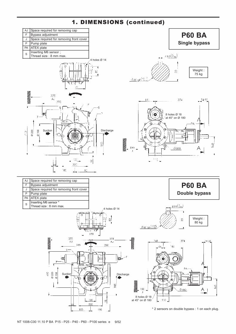
9/52NT 1008-C00 11.10 P BA P15 - P25 - P40 - P60 - P100 series e
1. DIMENSIONS (continued)AJ Space required for removing cap
F Bypass adjustment
J Space required for removing front cover
P Pump plate
PA ATEX plate
SInserting M6 sensor ;
Thread size : 8 mm max.
4 holes Ø 14
8 holes Ø 18
at 45° on Ø 180
DischargeSuction
Weight :
75 kg
8 holes Ø 18
at 45° on Ø 180
Suction Discharge
Weight :
80 kg
4 holes Ø 14
AJ Space required for removing cap
F Bypass adjustment
J Space required for removing front cover
P Pump plate
PA ATEX plate
SInserting M6 sensor *
Thread size : 8 mm max.
Ø 2
20
Ø 1
58
22
Ø 2
20
Ø 1
58
22
P60 BADouble bypass
P60 BASingle bypass
* 2 sensors on double bypass : 1 on each plug.

10/52NT 1008-C00 11.10 P BA P15 - P25 - P40 - P60 - P100 series e
1. DIMENSIONS (continued)
AJ Space required for removing cap
F Bypass adjustment
J Space required for removing front cover
P Pump plate
K Reheating jacket port
V Draining the jacket
Weight :
83 kg
K Reheating jacket port
V Draining the jacket
J Space required for removing front cover
P Pump plate
4 holes Ø 14
8 holes Ø 18 at 45° on Ø 180
for CB ISO PN16 DN100
4 M12 at 90°
on Ø 65
for CB ISO
PN16 DN15
8 holes Ø 18 at 45° on Ø 180
for CB ISO PN16 DN100
4 holes Ø 14
4 M12 at 90° on Ø 65
for CB ISO PN16 DN15
Pump shaft
View B
4 M12 at 90° on Ø 65
for CB ISO PN16 DN15
Pump shaft
View B
4 M12 at 90°
on Ø 65
for CB ISO
PN16 DN15
Weight :
77 kg
Ø 2
20
Ø 1
58
22
Ø 1
58
Ø 2
20
22
P60 BAJacket
Single bypass
P60 BAJacket
Stirrup

11/52NT 1008-C00 11.10 P BA P15 - P25 - P40 - P60 - P100 series e
1. DIMENSIONS (continued)
J Space required for removing front cover
P Pump plate
PA ATEX plate
Weight :
150 kg
P100 BAStirrup
AJ Space required for removing cap
F Bypass adjustment
J Space required for removing front cover
P Pump plate
K Reheating jacket port
V Draining the jacket
4 M12 at 90° on Ø 65
for CB ISO PN16 DN15
8 holes Ø 18 at 45° on Ø 180
for CB ISO PN16 DN100
4 holes Ø 14
Pump shaft
View B
4 M12 at 90°
on Ø 65
for CB ISO
PN16 DN15
8 holes Ø 18 at 45°
on Ø 210
Weight :
83 kg
Ø 1
58
Ø 2
20
22
Ø 2
50
Ø 1
88
24
P60 BAJacket
Double bypass
4 holes Ø 18
DischargeSuction

12/52NT 1008-C00 11.10 P BA P15 - P25 - P40 - P60 - P100 series e
1. DIMENSIONS (continued)
AJ Space required for removing cap
F Bypass adjustment
J Space required for removing front cover
P Pump plate
PA ATEX plate
SInserting M6 sensor
Thread size : 8 mm max.4 holes Ø 18
8 holes Ø 18 at 45°
on Ø 210
Weight :
175 kg
Weight :
195 kg
DischargeSuction
24
Ø 1
88
Ø 2
50
8 holes Ø 18
at 45° on Ø 210
P100 BADouble bypass
P100 BASingle bypass
DischargeSuction
24
Ø 1
88
Ø 2
50
4 holes Ø 18
AJ Space required for removing cap
F Bypass adjustment
J Space required for removing front cover
P Pump plate
PA ATEX plate
SInserting M6 sensor
Thread size : 8 mm max.

13/52NT 1008-C00 11.10 P BA P15 - P25 - P40 - P60 - P100 series e
1. DIMENSIONS (continued)
4 holes Ø 18
4 M12 at 90° on Ø 65
for CB ISO PN16 DN15
Pump shaft
View B
4 M12 at 90°
on Ø 65
for CB ISO
PN16 DN15
4 M12 at 90° on Ø 65
for CB ISO PN16 DN15
Pump shaft
View B
4 M12 at 90° on Ø 65
for CB ISO PN16 DN15
4 holes Ø 18
Weight :
126 kg
Weight :
138 kg
Ø 2
50
Ø 1
88
Ø 2
50
Ø 1
88
8 holes Ø 18
at 45° on Ø 210
for CB ISO
PN16 DN125
8 holes Ø 18
at 45° on Ø 210
for CB ISO
PN16 DN125
24
24
K Reheating jacket port
V Draining the jacket
J Space required for removing front cover
P Pump plate
AJ Space required for removing cap
F Bypass adjustment
J Space required for removing front cover
K Reheating jacket port
P Pump plate
V Draining the jacket
P100 BAJacket
Single bypass
P100 BAJacket
Stirrup

14/52NT 1008-C00 11.10 P BA P15 - P25 - P40 - P60 - P100 series e
1. DIMENSIONS (continued)AJ Space required for removing cap
F Bypass adjustment
J Space required for removing front cover
K Reheating jacket port
P Pump plate
V Draining the jacket
Pump shaft
View B
4 M12 at 90° on Ø 65
for CB ISO PN16 DN15
4 M12 at 90° on Ø 65
for CB ISO PN16 DN15
4 holes Ø 18
Weight :
149 kg
Ø 1
88
8 holes Ø 18
at 45° on Ø 210
for CB ISO
PN16 DN125
24
P100 BAJacket
Double bypass
Ø 2
50

2.1 Choice of pumpTo obtain the service expected from a MOUVEX P series
pump, regarding both performance and longevity, it is
vital that the type of pump, its speed and the materials
used for its construction are determined as a function of
the pump output, its installation and operating conditions.
You can contact our Technical Services at any time to
ask for the information you require.
2.2 Pipe diameterIn order to achieve the best usage conditions, it is impor-
tant to take the following recommendations into account
when it comes to pipe dimensions :
• The pipe diameter should be chosen as a function of
pipe length and the flow rate and viscosity of the pum-
ped liquid, so that any head loss remains within the per-
missible limits for the motor/pump unit. Therefore it is
difficult to give general and precise directions. However,
it is never a disadvantage to over-dimension pipe dia-
meters, especially for the section on the inlet side.
• In the case of thin liquids and the piping on the dischar-
ge side, one can generally allow a diameter equal to
that of the ports on the pump and a larger diameter for
the piping on the inlet side, if the value for the inlet
power of the pump is negative or especially high.
• In the case of viscous liquids, special care should be
given to choosing pipe diameters. In fact, the variation
in head loss is proportional to viscosity and inversely
proportional to the diameter as power of 4. A slight
reduction in the pipe diameter could have serious
consequences for the operating conditions of the pump.
Our Technical Services are always available to provide
you with precise data if you give them accurate informa-
tion or, better still, the installation plans.
2.3 Piping assemblyIn order to achieve the best usage conditions, it is impor-
tant to take the following recommendations into account
when it comes to fitting pipes :
• The location of the pump in the transfer or recycling cir-
cuit should always be determined so as to reduce the
height and length of the piping as much as possible.
• Wherever possible, siphons and reverse slopes should
be avoided in the inlet piping.
• Particular care needs to be taken with the sealing on
the inlet side to prevent air entering.
• Pipe elbows must always have a large radius (more
than 3 times the diameter of the pipes) and must not be
mounted too close to the pump flanges (min. recom-
mended distance : 10 times the diameter of the pipes),
on both the inlet and discharge sides.
• The pipes are supported and aligned with the pump in
such a way as to avoid putting stress on the pump
flanges. Non-compliance with this instruction can lead
to deformation of pump parts, misalignment of bearings
and accelerated material wear, even causing parts to
break.
• For ease of adjustment and checking, it is recommen-
ded that pressure tapping ports for pressure
gauges/vacuum gauges be provided as close as pos-
sible to the pump’s inlet ports (preferably, at a distance
of less than 5 times the diameter of the piping).
• If the suction head is especially high or if you want to
prevent the pipes emptying at shutdown, you can ins-
tall a foot valve. It should have a large diameter so as
not to generate additional head loss.
• We recommend placing valves as close as possible to
the pump ports to avoid having to drain the entire sys-
tem each time maintenance is carried out. These
valves should have the same diameter as the pipes
and preferably by full bore models.
• All these steps should be taken to prevent foreign
bodies entering the pump (the use of a filter in the
pump inlet pipe is strongly recommended).
• Before installing new pipes or tanks, be sure to clean
them very carefully to remove any solder, rust, etc.
which could be carried along with the water and cause
excessive pump wear.
• The pipes should be designed to allow for thermal
expansion/contraction (the use of flexible hoses or
expansion loops is recommended).
• If the liquid may freeze or solidify, prepare for draining
the piping by installing drain taps at the low points and
air vents at the high points.
15/52NT 1008-C00 11.10 P BA P15 - P25 - P40 - P60 - P100 series e
2. INSTALLATION

2.4 Direction of rotation• In its standard configuration, the MOUVEX P series
pump is supplied as non-reversible and with counter-
clockwise rotation.
NOTE :THE VIEWS CONTAINED IN THIS INSTRUCTION MANUALSHOW PARTS IN THE STANDARD DIRECTION OF ROTATION.
The rule governing the inlet side and the direction of
rotation is as follows :
• The inlet will be on the left side of the pump if the direc-
tion of rotation is counterclockwise (seen from the
discharge side).
• The inlet will be on the right side of the pump if the
direction of rotation is clockwise.
However, rotation in the opposite direction to that for
which the pump is designed is permitted for 5 minutes
maximum.
The direction of rotation can be reversed :
• On request at the time the order is placed. In this case,
the pump will be supplied with clockwise rotation.
• Manually, by referring to the relevant §.
It is also possible to order a reversible-direction MOUVEX
P series pump which can be operated for an unlimited
time in either direction.
REGARDLESS OF THE INTERNAL DESIGN OF THE PUMP,
THE DIRECTION OF ROTATION SHOULD NOT BE CHAN-
GED UNTIL THE PUMP HAS COME TO A COMPLETE STOP.
2.5 Protecting the system against overpres-sure
It is recommended that a safety device be used to pro-
tect the system from overpressures.
The standard pump is supplied fitted with a single
bypass to protect the system in one operating direction.
This is to say that its orientation is a function of the ope-
rating direction of the pump (see § BYPASS).
It is also possible to order the following options :
• Bypass clamp : the pump then has no other integrated
safety device. In that case, it is strongly recommended
to install a pressure switch to limit any overpressure.
• Double bypass : Here, the pump is fitted with an inte-
grated safety device to protect the system in both
directions of operation.
If the pump is to be used in both directions of rotation
(whatever the operating conditions), it is recommended
that a device (pressure switch, double bypass, etc.) be
used to protect the pump from overpressures, whatever
the direction of operation.
2.6 CleaningSince the pumps are delivered well greased, they must
be cleaned before starting them up (especially when
transferring food products, for example).
Cleaning can be done either by circulating an appropria-
te liquid, or by removing the front cover of the pump and
carefully cleaning the internal parts (to do so, refer to the
section on pump maintenance).
INCORRECT SETTINGS OF THE PRESSURERELIEF VALVE CAN CAUSE PUMPCOMPONENT FAILURE, PERSONALINJURY, AND PROPERTY DAMAGE.
WARNING
Hazardous pressure can cause
personal injury or property damage.
FAILURE TO INSTALL ADEQUATELYSIZED PRESSURE RELIEF VALVE(S)CAN CAUSE PROPERTY DAMAGE, PER-SONAL INJURY OR DEATH.
WARNING
Hazardous pressure can cause
personal injury
or property damage.
Counterclockwise direction of rotation
CAUTION
16/52NT 1008-C00 11.10 P BA P15 - P25 - P40 - P60 - P100 series e
2. INSTALLATION (continued)

2.7 Heating jacket variant
2.7.1 Technical characteristics
To avoid any liquid solidification in the pump, two heating
jackets are located on each side of the body.
Heating jackets permits the circulation of steam or liquid
up to 250°C and up to 12 bar (maximum pressure).
Jacket connections are :
• P15 - P25 pumps : 3/4" B.S.P.F. tapped holes.
• P40 - P60 - P100 pumps : ISO PN16 DN15 flanges +
4 holes M12 at 90° on Ø 65.
2.7.2 Connection system
The direction of the heating circuit connection to the jac-
ket depends on the nature of the heating fluid :
• If using steam, the inlet will be on the upper opening and
outlet will be on the lower opening.
P15 - P25
P40 - P60 - P100
• If using liquid, the inlet will be on the lower opening and
outlet will be on the upper opening.
P15 - P25
P40 - P60 - P100
• Draining the product when hot could cause serious
injuries or damage.
2.8 Installation of units
The correct seating of the pump is vital for its efficient ope-
ration and its longevity. The base must be flat, level and
sufficiently resistant to absorb the stresses caused by the
motor-driven pump without deformation (if it is made of
concrete, it must comply with standard BAEL 91).
In the case where the unit is fastened by anchor lugs or
bolts, it must be carefully wedged to prevent any defor-
mation of the chassis when tightening the bolts.
Deformation of the chassis will cause stress prejudicial
to the pump and the drive device and put the coupling
out of true alignment, thereby causing vibrations, noise
and premature wear. Care must be taken so that the
chassis is clear of the ground, apart from the base
plates.
If the chassis is a one-piece unit in doubled plate, it is
recommended that a horizontal clearance of about 50
cm be left between one section of the chassis and the
other to allow access for fastening the nuts on the pump,
reduction gearbox and motor. In all cases, the clearance
around the motor-driven pump should all room for
demounting the pump (for distances, refer to the dimen-
sion drawing at the start of the notice).
The chassis is equipped with a ground connection that
must be used to protect people and equipment.
BEFORE DRAINING THE HEATING JAC-KET, IT IS ESSENTIAL TO MAKE SURETHAT THE PUMP HEATING CIRCUIT ANDHEATING JACKET ARE NO LONGERPRESSURIZED.
WARNING
Hazardous pressure can cause
personal injury or property damage.
BE CAREFUL WITH THE WEIGHT OFTHE PARTS WHEN THEY ARE BEINGREMOVED.
WARNING
The weight of the parts canbe dangerous and may
provoke bodily injuries ormaterial damages.
17/52NT 1008-C00 11.10 P BA P15 - P25 - P40 - P60 - P100 series e
2. INSTALLATION (continued)
18/52NT 1008-C00 11.10 P BA P15 - P25 - P40 - P60 - P100 series e
2. INSTALLATION (continued)
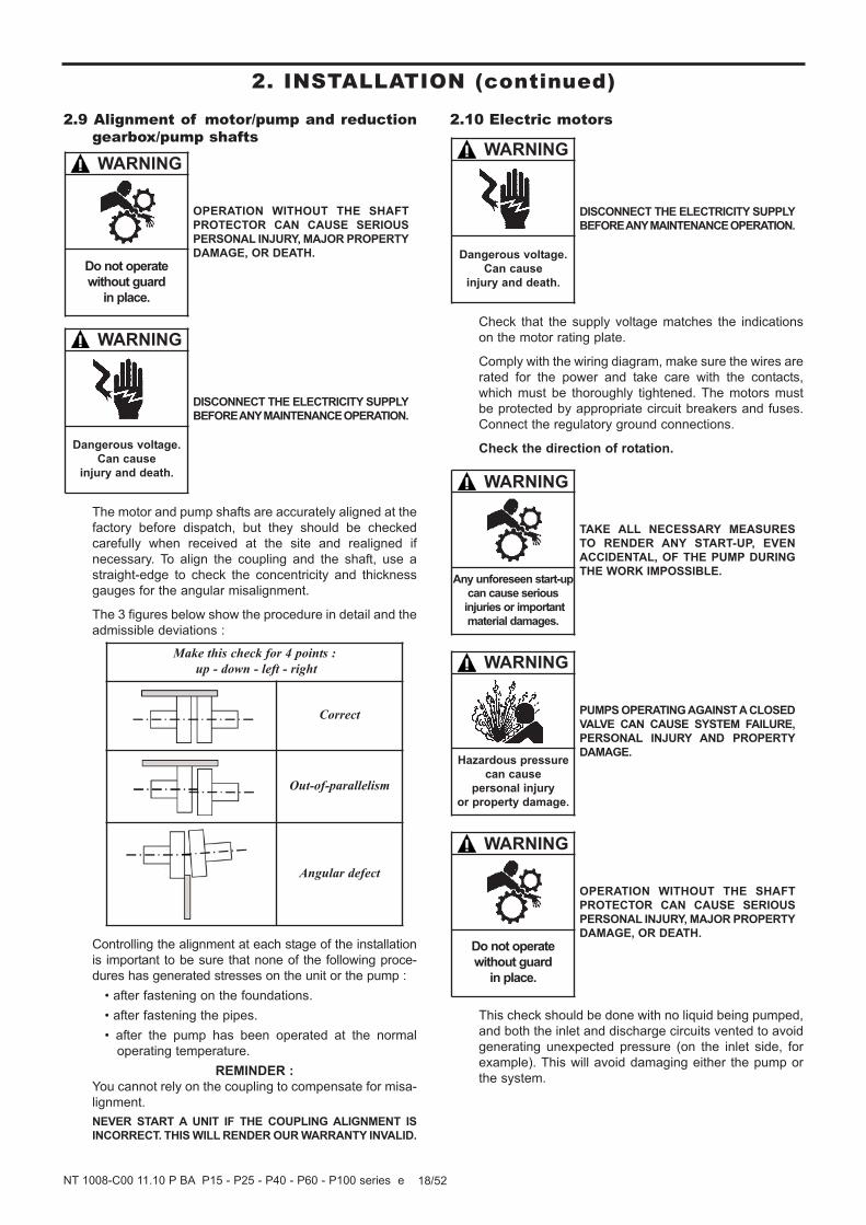
2.9 Alignment of motor/pump and reductiongearbox/pump shafts
The motor and pump shafts are accurately aligned at the
factory before dispatch, but they should be checked
carefully when received at the site and realigned if
necessary. To align the coupling and the shaft, use a
straight-edge to check the concentricity and thickness
gauges for the angular misalignment.
The 3 figures below show the procedure in detail and the
admissible deviations :
Controlling the alignment at each stage of the installation
is important to be sure that none of the following proce-
dures has generated stresses on the unit or the pump :
• after fastening on the foundations.
• after fastening the pipes.
• after the pump has been operated at the normal
operating temperature.
REMINDER :
You cannot rely on the coupling to compensate for misa-
lignment.
NEVER START A UNIT IF THE COUPLING ALIGNMENT ISINCORRECT. THIS WILL RENDER OUR WARRANTY INVALID.
2.10 Electric motors
Check that the supply voltage matches the indications
on the motor rating plate.
Comply with the wiring diagram, make sure the wires are
rated for the power and take care with the contacts,
which must be thoroughly tightened. The motors must
be protected by appropriate circuit breakers and fuses.
Connect the regulatory ground connections.
Check the direction of rotation.
This check should be done with no liquid being pumped,
and both the inlet and discharge circuits vented to avoid
generating unexpected pressure (on the inlet side, for
example). This will avoid damaging either the pump or
the system.
Make this check for 4 points :up - down - left - right
Correct
Out-of-parallelism
Angular defect
DISCONNECT THE ELECTRICITY SUPPLYBEFORE ANY MAINTENANCE OPERATION.
WARNING
Dangerous voltage.Can cause
injury and death.
OPERATION WITHOUT THE SHAFTPROTECTOR CAN CAUSE SERIOUSPERSONAL INJURY, MAJOR PROPERTYDAMAGE, OR DEATH.
WARNING
Do not operatewithout guard
in place.
PUMPS OPERATING AGAINST A CLOSED
VALVE CAN CAUSE SYSTEM FAILURE,
PERSONAL INJURY AND PROPERTYDAMAGE.
WARNING
Hazardous pressure can cause
personal injury
or property damage.
TAKE ALL NECESSARY MEASURES
TO RENDER ANY START-UP, EVEN
ACCIDENTAL, OF THE PUMP DURING
THE WORK IMPOSSIBLE.
WARNING
Any unforeseen start-up
can cause serious
injuries or important
material damages.
OPERATION WITHOUT THE SHAFTPROTECTOR CAN CAUSE SERIOUS
PERSONAL INJURY, MAJOR PROPERTYDAMAGE, OR DEATH.
WARNING
Do not operate
without guard in place.
DISCONNECT THE ELECTRICITY SUPPLYBEFORE ANY MAINTENANCE OPERATION.
WARNING
Dangerous voltage.Can cause
injury and death.

Start the pump empty to check that the connections are
good and that the direction of rotation corresponds to the
system intake and discharge directions. If it is necessa-
ry to reverse the direction of rotation, follow the instruc-
tions below :
Three-phase motor : switch any 2 current input wires.
Bi-phase motor : switch two same phase wires.
Single-phase motor : follow the instructions on the notice
supplied with the motor.
2.11 Diesel engines drive
Do not forget that these engines are not reversible. It is
therefore vital to carefully check the inlet and outlet sides
of the pump before connecting the pump unit to the piping.
The use of diesel engines drive is now well known.
Nevertheless, we strongly recommend that you carefully
read the technical manuals concerning them.
THE SURFACES OF THE PUMP CANBE AT A TEMPERATURE LIABLE TOCAUSE INJURY OR SEVERE DAMAGE.
CAUTION
Excessive temperature-
can cause injury or
severe damage.
19/52NT 1008-C00 11.10 P BA P15 - P25 - P40 - P60 - P100 series e
2. INSTALLATION (continued)

20/52NT 1008-C00 11.10 P BA P15 - P25 - P40 - P60 - P100 series e
3. USE
3.1 Pumping hot liquids
When pumping hot liquids, make your you retighten
screws and bolts after starting for the first time in order
to compensate for contraction.
3.2 Pump full of liquid when stopped
If the pump circuit is to be located between valves and/or
a non-return valve, you need to take account of the
variations in temperature that can lead to contraction of
the liquid in the circuit. In this case, you need to provide
some means of compensating for the contraction. A
discharge valve may be sufficient. The opening pressu-
re for this valve should be compatible with the permitted
pressure for the other components in the circuit.
It is also advisable to fit a discharge device to allow the
circuit to be completely emptied for any maintenance work.
In the case of liquids containing particles settling on
shut-down, it is necessary to make sure the consistency
of the deposit will not impede restarting the pump.
3.3 Noise levelThe sound level of a pump is greatly influenced by its
conditions of use. Cavitation and pumping products with
high gas contents generally increases the sound level.
Under the following pumping conditions :
• excluding cavitation
• maximum differential pressure : 12 bar
• speed of rotation 1000 rpm
• product viscosity of 1 cSt
The sound level reached for the MOUVEX P BA series
pump in good conditions without the drive is less than :
• P15 - P25. . . 74 dB(A)
• P40 - P60. . . 76 dB(A)
• P100. . . . . . . 78 dB(A)
3.4 Starting-up the pump
Before starting the pump, make sure that the following
conditions are met :
• The circuit should be in one of its pumping configu-
rations, with the appropriate valves open, especially
on the intake side.
• For products requiring heating, they must be brought
to their pumping temperature before starting the
pump.
3.5 Running without liquid in the pumpMOUVEX TVP (PEEK) or bronze vane pumps P Series
can run without liquid in the pump for 5 minutes without
causing damage, in particular during pump priming.
The running without liquid in the pump is forbidden for
steel vane pumps.
OPERATION WITHOUT THE SHAFT
PROTECTOR CAN CAUSE SERIOUS
PERSONAL INJURY, MAJOR PROPERTY
DAMAGE, OR DEATH.
WARNING
Do not operatewithout guard
in place.
FAILURE TO RELIEVE SYSTEM PRESSURE
PRIOR TO PERFORMING PUMP SERVICE
OR MAINTENANCE CAN CAUSE PERSONAL
INJURY OR PROPERTY DAMAGE.
WARNING
Hazardous pressure
can cause
personal injury
or property damage.
IF PUMPING HAZARDOUS OR TOXIC
FLUIDS, THE SYSTEM MUST BE FLUSHED
PRIOR TO PERFORMING ANY SERVICE
OPERATION.
WARNING
Toxic or hazardous
fluids can cause
serious injury.
FAILURE TO INSTALL ADEQUATELYSIZED PRESSURE RELIEF VALVE(S)
CAN CAUSE PROPERTY DAMAGE, PER-
SONAL INJURY OR DEATH.
WARNING
Hazardous pressure
can cause
personal injury
or property damage.
THE SURFACES OF THE PUMP CANBE AT A TEMPERATURE LIABLE TOCAUSE INJURY OR SEVERE DAMAGE.
CAUTION
Excessive temperature-
can cause injury or
severe damage.

21/52NT 1008-C00 11.10 P BA P15 - P25 - P40 - P60 - P100 series e
3. USE (continued)
3.6 Shutting down the pumpWhen shutting down the pump, we recommend waiting
for it to stop completely before closing the valves, espe-
cially the inlet valve.
3.7 Storage
MOUVEX pumps and motor-driven pumps are well lubri-
cated when delivered to protect the internal parts during
brief storage in a building where :
• the temperature remains between 10°C and 49°C.
• the relative humidity does not exceed 60%.
• exposure to vibration is limited (maximum movement :
0,05 mm).
We recommend the following procedure for longer periods
of storage :
3.7.1 Storage
The recommendations from the manufacturer should be
followed if the pump is stored with its gear motor.
Pump ports should be filled with a non-corrosive liquid
that it compatible with the pump components in order to
prevent corrosion.
Unpainted external surfaces of the pump (e.g. shafts,
couplings, etc.) should be covered in some form of anti-
corrosion protection.
The bearing should be well greased. If the pump is to be
stored for more than three years, the grease should be
replaced every three years to prevent it degrading (see
§ CHANGING THE BEARING for how to remove the cover).
The best storage conditions are inside a building that
meets the conditions set out above.
If inside storage is not possible, the materials should be
covered to prevent direct exposure to sun and rain. This
protection should also prevent condensation.
It is recommended to turn the pump by hand every two
months to distribute the lubricant around the interior.
Items should then be placed where there is no risk of
damage if they are moved slightly by vibrations.
3.7.2 Restarting
Follow the standard start-up procedure for the pump/
motor-driven pump, as well as the instructions below.
Turn the pump by hand to make sure the parts move
freely.
Remove the cover as explained in § CHANGING THE
BEARING and replace the grease used to lubricate the
bearing.
If the pump has a safety bypass, remove it and inspect
the parts and make sure they move freely (see §
BYPASS for removal instructions).
3.8 LubricationIf the type of liquid requires it, the pump should be lubri-
cated before each start-up, after each shutdown and
every 3 or 4 hours during continuous operation.
Preference should be given to lubricants that will not dis-
solve in the pumped liquid and, if hot liquids are invol-
ved, to lubricants that maintain their viscosity at opera-
ting temperatures.
3.9 ScrappingThe pump must be scrapped in compliance with the
regulations in force.
During this operation, particular care must be paid to the
drainage stages of the pump (pumped product).
IF PUMPING HAZARDOUS OR TOXICFLUIDS, THE SYSTEM MUST BE FLUSHEDPRIOR TO PERFORMING ANY SERVICEOPERATION.
WARNING
Toxic or hazardousfluids can causeserious injury.
4. NECESSARY TOOLS AND TIGHTENING TORQUES
4.1 Necessary tools• Open-end spanners 8 - 11 - 13 - 16 - 17
• Socket wrench 13
• Opening circlip pliers
• Screwdriver
• Extractor
• Torque wrench
• Wrench for 6 hexagonal hollows of 3
• Elastic bands
4.2 Assembly torques• M6.............10 Nm
• M8.............18 Nm
• M10...........30 Nm
• M12...........50 Nm

22/52NT 1008-C00 11.10 P BA P15 - P25 - P40 - P60 - P100 series e
Before any disassembly, make sure that the pump has been drained and take all the necessary precautions to prevent it from
starting up. The pump must not start up, even accidentally.
DISCONNECT THE ELECTRICITY SUPPLYBEFORE ANY MAINTENANCE OPERATION.
WARNING
Hazardous pressure
can cause
personal injury
or property damage.
WARNING
The weight of the parts canbe dangerous and may
provoke bodily injuries ormaterial damages.
THE SURFACES OF THE PUMP CANBE AT A TEMPERATURE LIABLE TOCAUSE INJURY OR SEVERE DAMAGE.
CAUTION
Excessive temperature-
can cause injury orsevere damage.
WARNING
Hazardous pressure can cause
personal injury or property damage.
WARNING
Hazardous or toxicfluids can causeserious injury.
CAUTION
Slippery lubricant.Spills should be
cleaned up.
TAKE ALL NECESSARY MEASURES
TO RENDER ANY START-UP, EVENACCIDENTAL, OF THE PUMP DURING
THE WORK IMPOSSIBLE.
WARNING
Any unforeseen start-up can cause serious
injuries or important material damages.
5. OPENING AND CLOSING THE NON-DRIVE SIDE BASE
WARNING
Dangerous voltage.Can cause
injury or death.
FAILURE TO RELEASE ALL SYSTEM AIRAND WHEN EQUIPPED, HYDRAULIC PRES-
SURE, CAN CAUSE PROPERTY DAMAGE,
PERSONAL INJURY OR DEATH.
BE CAREFUL WITH THE WEIGHT OF
THE PARTS WHEN THEY ARE BEING
REMOVED.
DISCONNECTING THE FLUID OR PRES-SURE CONTAINMENT COMPONENTSDURING PUMP OPERATION CAN CAUSESERIOUS PERSONAL INJURY, DEATHOR MAJOR PROPERTY DAMAGE.
IF PUMPING HAZARDOUS OR TOXICFLUIDS, THE SYSTEM MUST BE FLUSHED
PRIOR TO PERFORMING ANY SERVICE
OPERATION.
THE PUMP LUBRICANT IS VERY SLIPPERY
AND MAY CAUSE SERIOUS INJURY.
ANY SPILLS MUST BE CLEANED UP.

5.1 Opening the non-drive side base• Loosen the 6 screws 410.
• Place 2 screws 410 in the 2 diametrically opposed tapped
holes.
• Detach the front cover 401b of the body by screwing
the 2 screws at the same time.
• When the cover is free on the shaft, withdraw it manually
while supporting it.
• Check the seal 403.
• Check the bushing 407 inside the cover 401b (see §
MAINTENANCE).
5.2 Checking the vanes
• Remove a vane 317 situated in an horizontal plane.
• Check it for wear (see § MAINTENANCE). In the case
of abnormal wear, check the state of the body and front
cover faces.
• Replace the vane (with a new one if necessary),
making sure it is fitted in the right direction (see details
below) and making sure it slides properly in its slot.
• By hand, turn the pump shaft to bring the next vane into
a horizontal plane.
Then proceed in the same way for each vane.
5.3 Changing the bushingDismantling :
• Place the front cover 401b vertically on side jacket.
• Insert the extractor inside the ring 407, as far as the front
cover 401b.
• When the extractor is in place, remove the ring 407.
Reassembly :
• Place the front cover 401b vertically on side jacket.
• Offer up the ring 407 on the hole.
• Fit the ring by pushing it on with a sleeve using a press.
The face of the ring 407 must be in line with that of the
front cover 401b.
Rotor 6 vanes steelRotor 6 vanes TVP
Rotor 12 vanes TVP
23/52NT 1008-C00 11.10 P BA P15 - P25 - P40 - P60 - P100 series e
5. OPENING AND CLOSING THE NON-DRIVE SIDE BASE(continued)

5.4 Closing the non-drive side base• Check the seal 403, and replace if necessary.
• Place the front cover 401b on the shaft 501 and tighten
it as much as possible by hand.
• Tighten the 6 screws 410.
• Turn the shaft as you tighten the screws 410.
24/52NT 1008-C00 11.10 P BA P15 - P25 - P40 - P60 - P100 series e
5. OPENING AND CLOSING THE NON-DRIVE SIDE BASE(continued)

25/52NT 1008-C00 11.10 P BA P15 - P25 - P40 - P60 - P100 series e
6. OPENING AND CLOSING THE DRIVE SIDE BASE
Before any disassembly, make sure that the pump has been drained and take all the necessary precautions to prevent it from star-
ting up.The pump must not start up, even accidentally.
Uncouple the pump by removing the coupling sleeve.
Remove the pump mounting screws.
Place it on a workbench or on a flat surface free from obstructions.
DISCONNECT THE ELECTRICITY SUPPLYBEFORE ANY MAINTENANCE OPERATION.
WARNING
Hazardous pressure
can cause
personal injury
or property damage.
WARNING
The weight of the parts canbe dangerous and may
provoke bodily injuries ormaterial damages.
THE SURFACES OF THE PUMP CANBE AT A TEMPERATURE LIABLE TOCAUSE INJURY OR SEVERE DAMAGE.
CAUTION
Excessive temperature-
can cause injury orsevere damage.
WARNING
Hazardous pressure can cause
personal injury or property damage.
WARNING
Hazardous or toxicfluids can causeserious injury.
CAUTION
Slippery lubricant.Spills should be
cleaned up.
TAKE ALL NECESSARY MEASURES
TO RENDER ANY START-UP, EVENACCIDENTAL, OF THE PUMP DURING
THE WORK IMPOSSIBLE.
WARNING
Any unforeseen start-up can cause serious
injuries or important material damages.
WARNING
Dangerous voltage.Can cause
injury or death.
FAILURE TO RELEASE ALL SYSTEM AIRAND WHEN EQUIPPED, HYDRAULIC PRES-
SURE, CAN CAUSE PROPERTY DAMAGE,
PERSONAL INJURY OR DEATH.
BE CAREFUL WITH THE WEIGHT OF
THE PARTS WHEN THEY ARE BEING
REMOVED.
DISCONNECTING THE FLUID OR PRES-SURE CONTAINMENT COMPONENTSDURING PUMP OPERATION CAN CAUSESERIOUS PERSONAL INJURY, DEATHOR MAJOR PROPERTY DAMAGE.
IF PUMPING HAZARDOUS OR TOXICFLUIDS, THE SYSTEM MUST BE FLUSHED
PRIOR TO PERFORMING ANY SERVICE
OPERATION.
THE PUMP LUBRICANT IS VERY SLIPPERY
AND MAY CAUSE SERIOUS INJURY.
ANY SPILLS MUST BE CLEANED UP.

6.1 Opening the drive side base• Loosen the 6 screws 410.
• Place 2 screws 410 in the 2 diametrically opposed tapped
holes.
• Detach the front cover of the body by screwing the 2
screws at the same time.
• Withdraw the base 401a in such a way as to release
the rotor 301 from a little more that half of the pump
body 401a.
• Hold the vanes 317 in place by means of suitable straps
(elastic, bracelets...).
• Check the seal 403.
6.2 Dismantling the vanes and pushrods• Place the front cover 401a and rotor 301 assembly on
a bench.
• Remove the straps and the vanes 317.
• Pull out the pushrods 318 by pushing them, if necessary,
with a screwdriver.
• Check the pushrods 318 for wear (see § MAINTENANCE)
and change them as necessary.
• Pull out the rotor 301.
• Remove the keyways 536.
• Check the wear of the keyways and of the 2 keys 536.
26/52NT 1008-C00 11.10 P BA P15 - P25 - P40 - P60 - P100 series e
6. OPENING AND CLOSING THE DRIVE SIDE BASE (continued)

27/52NT 1008-C00 11.10 P BA P15 - P25 - P40 - P60 - P100 series e
6. OPENING AND CLOSING THE DRIVE SIDE BASE (continued)
6.3 Changing the bushing• Loosen the 3 screws 726.
• Remove the front cover 401a from the strainer 725 by
sliding it along the shaft 501 (be careful not to drag the
shaft seal or subject it to any impact).
• Insert the extractor inside the ring 407, as far as the
front cover 401a.
• When the extractor is in place, remove the ring 407.
Reassembly :
• Place the front cover 401a vertically on the smaller sur-
face.
• Offer up the ring 407 on the hole.
• Fit the ring 407 by pushing it on with a sleeve using a
press. The face of the ring 407 must be in line with that
of the front cover 401a.
• Fit the front cover 401a on the strainer 725.
If there is a double shaft seal, index the seal insert and
the cover.
• Tighten the 3 screws 726.
6.4 Reassembly the vanes and pushrods• Position the shaft 501 vertically with the front cover 401a
facing down.
• Check the seal 403, and replace if necessary.
• Fit the seal 403 in the front cover 401a.
• Fit the keyways 536.
• Insert the rotor 301 on the shaft 501.
In the case of a rotor with 6 vanes, make sure the rotor
is facing the right direction. The rule for correct orienta-
tion is as follows : The rotor should be oriented such
that as the shaft rotates and turns to the discharge side,
the inside recesses are behind the vane, as seen by the
observer (fitting direction here is counterclockwise).
• Insert the pushrods 318 in the holes on the rotor 301(in this case where the rotor has 12 vanes, insert the
pushrods using orthogonal tightening).
• Insert the vanes 317 in the mounting direction (see
detail below) and check that they slide freely.
Rotor 6 vanes steelRotor 6 vanes TVP
Rotor 12 vanes TVP
CAUTION
CAUTION
28/52NT 1008-C00 11.10 P BA P15 - P25 - P40 - P60 - P100 series e
6. OPENING AND CLOSING THE DRIVE SIDE BASE (continued)
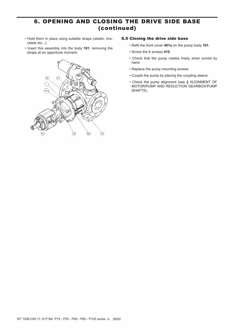
• Hold them in place using suitable straps (elastic, bra-
celets etc...).
• Insert this assembly into the body 101, removing the
straps at an opportune moment.
6.5 Closing the drive side base• Refit the front cover 401a on the pump body 101.
• Screw the 6 screws 410.
• Check that the pump rotates freely when turned by
hand.
• Replace the pump mounting screws.
• Couple the pump by placing the coupling sleeve.
• Check the pump alignment (see § ALIGNMENT OF
MOTOR/PUMP AND REDUCTION GEARBOX/PUMP
SHAFTS).

29/52NT 1008-C00 11.10 P BA P15 - P25 - P40 - P60 - P100 series e
7. CHANGING THE BALL BEARING
DISCONNECT THE ELECTRICITY SUPPLYBEFORE ANY MAINTENANCE OPERATION.
WARNING
Hazardous pressure
can cause
personal injury
or property damage.
WARNING
The weight of the parts canbe dangerous and may
provoke bodily injuries ormaterial damages.
THE SURFACES OF THE PUMP CANBE AT A TEMPERATURE LIABLE TOCAUSE INJURY OR SEVERE DAMAGE.
CAUTION
Excessive temperature-
can cause injury orsevere damage.
WARNING
Hazardous pressure can cause
personal injury or property damage.
WARNING
Hazardous or toxicfluids can causeserious injury.
CAUTION
Slippery lubricant.Spills should be
cleaned up.
TAKE ALL NECESSARY MEASURES
TO RENDER ANY START-UP, EVENACCIDENTAL, OF THE PUMP DURING
THE WORK IMPOSSIBLE.
WARNING
Any unforeseen start-up can cause serious
injuries or important material damages.
WARNING
Dangerous voltage.Can cause
injury or death.
FAILURE TO RELEASE ALL SYSTEM AIRAND WHEN EQUIPPED, HYDRAULIC PRES-
SURE, CAN CAUSE PROPERTY DAMAGE,
PERSONAL INJURY OR DEATH.
BE CAREFUL WITH THE WEIGHT OF
THE PARTS WHEN THEY ARE BEING
REMOVED.
DISCONNECTING THE FLUID OR PRES-SURE CONTAINMENT COMPONENTSDURING PUMP OPERATION CAN CAUSESERIOUS PERSONAL INJURY, DEATHOR MAJOR PROPERTY DAMAGE.
IF PUMPING HAZARDOUS OR TOXICFLUIDS, THE SYSTEM MUST BE FLUSHED
PRIOR TO PERFORMING ANY SERVICE
OPERATION.
THE PUMP LUBRICANT IS VERY SLIPPERY
AND MAY CAUSE SERIOUS INJURY.
ANY SPILLS MUST BE CLEANED UP.

Before any disassembly, make sure that the pump has been
drained, and take all the necessary precautions to prevent it
from starting up. The pump must not start up, even acciden-
tally.
Uncouple the pump by removing the coupling sleeve.
Remove the pump mounting screws.
Place it on a workbench or on a flat surface free from obstruc-
tions.
Dismantling :
• Remove the key 508.
• Carefully clean the shaft end with emery paper no. 320
to remove any trace of paint, oxidation, burrs, etc.
• Loosen the 4 screws 723.
• Remove the cover 705, taking care not to damage the
lip seal 707.
• Remove the circlips 537.
• Remove the washer 731.
• Remove the balls bearing 703 using the extractor :
pass the grippers behind the balls bearing while sliding
them into the holes of the strainer 725, using the shaft
end 501 as a support.
• Keep the washer in place 731.
Reassembly :
• Check that the washer 731 is pressed against the shoulder
of the shaft 501.
• Couple the balls bearing 703 on to the shaft by hand
(see § GREASING OF THE BALL BEARING).
• Push it on with a sleeve until it comes to bear against
the washer 731. In no case must the balls bearing be
pushed on to the shaft without support for the shaft 501.FAILURE TO FOLLOW THIS PROCEDURE CAN SERIOUS-LY DAMAGE THE INTERIOR OF THE PUMP.
• Place a second washer 731 against the balls bearing 703.
• Fit the circlips 537.
• Check the lip seal 707 and change it as necessary.
• Clean the sides of the cover 705 and of the strainer 725with a clean rag.
• Fit the lip seal 707 in the cover 705, with the lip facing
inward.
• Fit the cover 705 on the strainer 725.
• Screw the 4 screws 723.
• Check that the pump rotates freely when turned by hand.
• Put the pump back on the installation.
• Replace the pump mounting screws.
• Couple the pump by placing the coupling sleeve.
• Check the pump alignment (see § ALIGNMENT OF
MOTOR/PUMP AND REDUCTION GEARBOX/PUMP
SHAFTS).
30/52NT 1008-C00 11.10 P BA P15 - P25 - P40 - P60 - P100 series e
7. CHANGING THE BALL BEARING (continued)

31/52NT 1008-C00 11.10 P BA P15 - P25 - P40 - P60 - P100 series e
8. BYPASS
DISCONNECT THE ELECTRICITY SUPPLY
BEFORE ANY MAINTENANCE OPERATION.
WARNING
Hazardous pressure
can cause
personal injury or property damage.
WARNING
The weight of the parts canbe dangerous and may
provoke bodily injuries ormaterial damages.
THE SURFACES OF THE PUMP CANBE AT A TEMPERATURE LIABLE TOCAUSE INJURY OR SEVERE DAMAGE.
CAUTION
Excessive temperature-
can cause injury orsevere damage.
WARNING
Hazardous pressure
can cause
personal injury
or property damage.
WARNING
Hazardous or toxicfluids can causeserious injury.
CAUTION
Slippery lubricant.
Spills should becleaned up.
TAKE ALL NECESSARY MEASURES
TO RENDER ANY START-UP, EVENACCIDENTAL, OF THE PUMP DURING
THE WORK IMPOSSIBLE.
WARNING
Any unforeseen start-up can cause seriousinjuries or important
material damages.
WARNING
Dangerous voltage.
Can cause
injury or death.
FAILURE TO RELEASE ALL SYSTEM AIR
AND WHEN EQUIPPED, HYDRAULIC PRES-
SURE, CAN CAUSE PROPERTY DAMAGE,
PERSONAL INJURY OR DEATH.
BE CAREFUL WITH THE WEIGHT OFTHE PARTS WHEN THEY ARE BEINGREMOVED.
DISCONNECTING THE FLUID OR PRES-
SURE CONTAINMENT COMPONENTS
DURING PUMP OPERATION CAN CAUSE
SERIOUS PERSONAL INJURY, DEATH
OR MAJOR PROPERTY DAMAGE.
IF PUMPING HAZARDOUS OR TOXIC
FLUIDS, THE SYSTEM MUST BE FLUSHED
PRIOR TO PERFORMING ANY SERVICE
OPERATION.
THE PUMP LUBRICANT IS VERY SLIPPERYAND MAY CAUSE SERIOUS INJURY.ANY SPILLS MUST BE CLEANED UP.
Version with plug
Installing for
High Temperature

32/52NT 1008-C00 11.10 P BA P15 - P25 - P40 - P60 - P100 series e
8. BYPASS (continued)
8.1 Bypass operationThe compensated bypass operates like a valve, by auto-
matically limiting the discharge pressure at the value for
which it is adjusted.
When the discharge pressure reaches the adjusted pres-
sure of the spring, the valve 823 opens, thus permitting
the partial or total return of the liquid to the inlet side of
the pump.
The compensated bypass is used when the pump flow is
frequently diverted through its bypass, i.e. when the
discharge is closed, the compensated bypass is designed
to generate a very small increase of pressure, which
means that the motor will economically supply the
necessary additional power for specific working condi-
tions. It should be noted that the role of the bypass, as a
safety device, is limited to protecting the pump against
accidental over-pressure.
For all electric motors - unless the model used can hand-
le the increased load due to maximum overpressure -
(pump sending its flow through the bypass with the
spring tightened to the maximum) it is vital to provide
appropriate overload protection.
8.2 Bypass orientationThe single bypass only protects the pump in one direc-
tion of operation. Consequently it is necessary to check
that the pump’s direction of operation is correct by veri-
fying that the cap 827 is located on the inlet side. The
bypass must be reversed if in the wrong direction.
8.3 Bypass inversion• Loosen the 2 screws 859.
• Remove the bypass.
• Check the seals 858 and change them as necessary.
• Turn the bypass through 180°.
• Screw the 2 screws 859, taking care to balance the
tightening so that the bypass remains vertical.
8.4 Bypass adjustment
• Loosen the lock nut 835.
• Turn the adjustment nut 834 clockwise to increase the
discharge pressure and anticlockwise to decrease it.
• Once the adjustment is finished, screw the lock nut 835.
Adjustment of the bypass is satisfactory when the flow
meets the pump’s requirements and when the motor
bears, without incident, either excessive energy
consumption or the power increase due to the overpres-
sure seen upon closing the discharge. This is how the
bypasses of our pump units are adjusted, as a function
of the information provided by our Technical Services.
WARNING
Hazardous pressure
can cause
personal injury or property damage.
INCORRECT SETTINGS OF THE PRESSURE
RELIEF VALVE CAN CAUSE PUMP
COMPONENT FAILURE, PERSONAL
INJURY, AND PROPERTY DAMAGE.
Counterclockwise rotation
Version with plug
Installing for
High Temperature

33/52NT 1008-C00 11.10 P BA P15 - P25 - P40 - P60 - P100 series e
8. BYPASS (continued)
8.5 Obtaining the flow
If the flow is lower than anticipated, the cause may be
due to incorrect adjustment of the bypass valve. To cor-
rect it, see § BYPASS ADJUSTMENT.
Make sure that the pump is running well at the recom-
mended speed.
If during adjustment, you compress the spring to its limit
or disturb the operation of the motor, without obtaining
the flow required, this means that the motopump unit
must operate with a pressure higher than that for which
it was designed. In this case you should consult our
Technical Services.
When you obtain the required flow, make sure that the
motor can withstand the increased power due to the
overpressure created by closing off the discharge line.
If need be, adjust the bypass again to enable the motor
to obtain it.
8.6 Energy consumptionIf the energy consumption does not correspond to
expectations, the reason may be poor adjustment of the
bypass valve.
To correct it, close the discharge valve and adjust the
bypass (see § BYPASS ADJUSTMENT) until the energy
consumption is satisfactory.
8.7 Replacing the springBefore any disassembly, make sure that the pump has
been drained and take all the necessary precautions to
prevent it from starting up. The pump must not start up,
even accidentally.
Disassembly :
• Loosen the 2 screws 859.
• Lift off the bypass and place it on a bench or flat surface
free from obstructions.
• Set the bypass pressure to the minimum (see § BYPASS
ADJUSTMENT).
• Keep the bypass vertical during the rest of the process.
• Slowly loosen the screws 856.
THE SPRING IS ALWAYS UNDER SLIGHT TENSION.
• Remove the cap on the bypass 827 and its pressure
screw (825 - 826 - 831 - 834 - 835 - 837).
• Withdraw the bypass spring 824.
Reassembly :
• Keep the bypass vertical during this process.
• Insert the spring 824 into the bypass. Check the posi-
tion of the valve 823. It should rest flat on its support
and slide freely in its strainer.
• Replace the bypass cap 827 and pressure screw (825 -826 - 831 - 834 - 835 - 837).
• Slowly tighten the screws 856.
YOU WILL NEED TO COMPRESS THE SPRING SLIGHTLY
BEFORE YOU CAN TIGHTEN THE SCREWS.
• Check the 2 seals 858 and change them as necessary.
• Refit the bypass on the pump, checking the installation
direction in relation to the direction of operation.
• Tighten the 2 screws 859 equally so the bypass stays
vertical.
• Set the spring pressure to the desired value (see §
BYPASS ADJUSTMENT).
CAUTION
CAUTION
INCORRECT SETTINGS OF THE PRESSURERELIEF VALVE CAN CAUSE PUMPCOMPONENT FAILURE, PERSONALINJURY, AND PROPERTY DAMAGE.
WARNING
Hazardous pressure can cause
personal injury or property damage.

34/52NT 1008-C00 11.10 P BA P15 - P25 - P40 - P60 - P100 series e
9. SHAFT SEAL
9.1 Packing
DISCONNECT THE ELECTRICITY SUPPLYBEFORE ANY MAINTENANCE OPERATION.
WARNING
Hazardous pressure
can cause
personal injury
or property damage.
WARNING
The weight of the parts canbe dangerous and may
provoke bodily injuries ormaterial damages.
THE SURFACES OF THE PUMP CANBE AT A TEMPERATURE LIABLE TOCAUSE INJURY OR SEVERE DAMAGE.
CAUTION
Excessive temperature-
can cause injury orsevere damage.
WARNING
Hazardous pressure can cause
personal injury or property damage.
WARNING
Hazardous or toxicfluids can causeserious injury.
CAUTION
Slippery lubricant.Spills should be
cleaned up.
TAKE ALL NECESSARY MEASURES
TO RENDER ANY START-UP, EVENACCIDENTAL, OF THE PUMP DURING
THE WORK IMPOSSIBLE.
WARNING
Any unforeseen start-up can cause serious
injuries or important material damages.
WARNING
Dangerous voltage.Can cause
injury or death.
FAILURE TO RELEASE ALL SYSTEM AIRAND WHEN EQUIPPED, HYDRAULIC PRES-
SURE, CAN CAUSE PROPERTY DAMAGE,
PERSONAL INJURY OR DEATH.
BE CAREFUL WITH THE WEIGHT OF
THE PARTS WHEN THEY ARE BEING
REMOVED.
DISCONNECTING THE FLUID OR PRES-SURE CONTAINMENT COMPONENTSDURING PUMP OPERATION CAN CAUSESERIOUS PERSONAL INJURY, DEATHOR MAJOR PROPERTY DAMAGE.
IF PUMPING HAZARDOUS OR TOXICFLUIDS, THE SYSTEM MUST BE FLUSHED
PRIOR TO PERFORMING ANY SERVICE
OPERATION.
THE PUMP LUBRICANT IS VERY SLIPPERY
AND MAY CAUSE SERIOUS INJURY.
ANY SPILLS MUST BE CLEANED UP.

9.1.1 Operation of packing
The rings 629 have a static seal at the strainer 725 side
and a hydrodynamic seal at the shaft side 501 side.
The packing gland 631 must compress the rings 629 by
tightening the screws 729 while providing a slight leakage
to the outside.
The packing must always seep slightly to reduce friction
between the shaft 501 and the rings 629 and remove the
frictional heat that can cause the packing to overheat.
A seal is created by the rings 629 between the strainer
725 and the shaft 501.
LEAKING SHAFT SEALS :
• The shaft 501 is worn on the right of the packing.
• The rings 629 are not suitable for the pumped liquid
and have been attacked chemically and/or worn away
mechanically.
9.1.2 Replacement of packing
Before any disassembly, make sure that the pump has
been drained and take all the necessary precautions to
prevent it from starting up. The pump must not start up,
even accidentally. Uncouple the pump by removing the
coupling sleeve.
Remove the pump mounting screws.
Place it on a workbench or on a flat surface free from
obstructions.
Dismantling :
• Loosen the 2 screws 729 and their square nuts 730.
• Remove the 2 stirrups 636.
• Free the packing gland 631 by sliding it along the shaft
501.
• Carefully lift out the worn shaft seal.
Reassembly :
• Cut 5 rings with the diameter of the shaft from the
replacement packing.
• Insert them in the strainer 725, one after the other,
arranging them in such a way that the joints in the rings
629 do not merge into one another. The last ring must
not protrude from the strainer.
• Put back the packing gland 631.
• Reinstall the stirrups 636.
• Gently re-tighten the 2 screws 729 and square nuts
730 taking care to balance up the tightening so that the
packing gland enters straight into the strainer.
• Push in the packing gland 631 just enough to prevent
substantial leakage.
• Replace the pump on the installation.
• Replace the pump mounting screws.
• Couple the pump by placing the coupling sleeve.
• Check the pump alignment (see § ALIGNMENT OF
MOTOR/PUMP AND REDUCTION GEARBOX/PUMP
SHAFTS).
• Start up the pump.
• Keep tightening the screws 729, tightening as the new
shaft seal settles. Allow slight seepage of liquid neces-
sary for the lubrication and the cooling of the packing.
• Ascertain manually that there is no abnormal heating of
the strainer 725 due to overtightening of the packing
gland 631. If this happens, release the shaft seal by
loosening the 2 screws 729.
CAUTION
35/52NT 1008-C00 11.10 P BA P15 - P25 - P40 - P60 - P100 series e
9. SHAFT SEAL (continued)
* Loctite® is a registered brand.
Glued with Loctite® 243*View F

36/52NT 1008-C00 11.10 P BA P15 - P25 - P40 - P60 - P100 series e
9. SHAFT SEAL (continued)
9.2 MOUVEX mechanical shaft seal
DISCONNECT THE ELECTRICITY SUPPLYBEFORE ANY MAINTENANCE OPERATION.
WARNING
Hazardous pressure
can cause
personal injury
or property damage.
WARNING
The weight of the parts canbe dangerous and may
provoke bodily injuries ormaterial damages.
THE SURFACES OF THE PUMP CANBE AT A TEMPERATURE LIABLE TOCAUSE INJURY OR SEVERE DAMAGE.
CAUTION
Excessive temperature-
can cause injury orsevere damage.
WARNING
Hazardous pressure can cause
personal injury or property damage.
WARNING
Hazardous or toxicfluids can causeserious injury.
CAUTION
Slippery lubricant.Spills should be
cleaned up.
TAKE ALL NECESSARY MEASURES
TO RENDER ANY START-UP, EVENACCIDENTAL, OF THE PUMP DURING
THE WORK IMPOSSIBLE.
WARNING
Any unforeseen start-up can cause serious
injuries or important material damages.
WARNING
Dangerous voltage.Can cause
injury or death.
FAILURE TO RELEASE ALL SYSTEM AIRAND WHEN EQUIPPED, HYDRAULIC PRES-
SURE, CAN CAUSE PROPERTY DAMAGE,
PERSONAL INJURY OR DEATH.
BE CAREFUL WITH THE WEIGHT OF
THE PARTS WHEN THEY ARE BEING
REMOVED.
DISCONNECTING THE FLUID OR PRES-SURE CONTAINMENT COMPONENTSDURING PUMP OPERATION CAN CAUSESERIOUS PERSONAL INJURY, DEATHOR MAJOR PROPERTY DAMAGE.
IF PUMPING HAZARDOUS OR TOXICFLUIDS, THE SYSTEM MUST BE FLUSHED
PRIOR TO PERFORMING ANY SERVICE
OPERATION.
THE PUMP LUBRICANT IS VERY SLIPPERY
AND MAY CAUSE SERIOUS INJURY.
ANY SPILLS MUST BE CLEANED UP.

9.2.1 Operation of a MOUVEX mechanical shaftseal
The shaft 501 drives the rotating parts 697 (consisting of
the reservoir 612, the seal 613, the spring support 614,
the spring 615 (not shown here), the cage 616 and the
shaft seal carrier 641) by means of set screws 642. The
counterpart 604 is integrated with the shaft seal holder
601 by the seal 605 and the pin 627.
THE SEALING IS ACHIEVED :
• On the shaft, by ring seals 613 of rotating part 697.
• By the contact face between the rotating part 697 and
the fixed counterpart 604.
• Between the fixed counterpart 604 and the shaft seal
holder 601 by the seal 605.
Fluid tightness therefore depends on the condition of the
friction faces and ring seals.
REASONS FOR LEAKING SHAFT SEAL :
• Seal damaged during assembly (scratching on friction
faces, etc.).
• Shaft seal unsuitable for the liquid pumped (chemical
attack or mechanical damages to seals and counterparts).
• Normal wear of the shaft seal.
9.2.2 Replacing a MOUVEX mechanical shaftseal
Before undertaking disassembly, make sure that the pump
has been drained, and take the necessary precautions
to prevent it from starting up. The pump must not start up,
even accidentally.
Uncouple the pump by removing the coupling sleeve.
Remove the pump mounting screws.
Place it on a workbench or on a flat surface free from obs-
tructions.
Dismantling :
• Remove the shaft key 508.
• Carefully clean the end of the shaft with emery paper
no. 320 to remove all traces of paint, oxidation, burrs, etc.
• Unscrew the 4 screws 723.
• Remove the cover 705 without damaging the seal 707.
• Remove the circlip 537.
• Remove the washer 731.
• Using the bearing puller, remove the bearing 703 :
position the jaws behind the bearing, sliding them into
the openings in the housing 725 and pressing against
the shaft end 501.
• Remove the second washer 731.
• Unscrew the 4 screws 726.
• Slide the strainer unit 725 along the shaft 501 taking
care not to damage the lip seal 716 or the fixed coun-
terpart 604.
• Unscrew the 2 screws 729 and their square nuts 730.
• Remove the shaft seal holder 601.
• Remove the counterpart 604 and its ring seal 605remaining on the shaft seal holder 601.
• On the shaft, undo the screws 642 holding the rotating
part 697.
• Remove the rotating part 697 by sliding it along the
shaft 501.
37/52NT 1008-C00 11.10 P BA P15 - P25 - P40 - P60 - P100 series e
9. SHAFT SEAL (continued)
* Loctite® is a registered brand.
Glued with Loctite® 243*
View F

Reassembly :
• Check that the surfaces in contact with the counterpart
604 and rotating part 697 are in good condition.
• Check the ring seals 602 (2) - 605 (1) - 613 (1) and
change them as necessary.
• Check the lip seals 707 (1) - 716 (1) and replace if
necessary.
• Use a clean cloth to clean the surfaces in contact with
the shaft seal.
• Mount the counterpart 604 and its seal 605 in the shaft
seal holder, 601 inserting the pin 627 in the slot in the
counterpart.
• Lubricate the shaft 501 lightly.
• Slide the rotating part 697 of the shaft seal and its seal
613 along the shaft 501 until it abuts the circlip 511.
• Tighten the screws 642 to keep the rotating part 697 on
the shaft 501 (stop the screws loosening with Loctite®
643* or equivalent).
• Insert the shaft seal holder assembly 601 and the
counterpart 604 into the strainer 725 (be careful not to
bump the edge of the shaft seal counterpart 604).
• Tighten the 2 screws 729 and their nuts 730.
• Slide the strainer 725 assembly onto the shaft 501 until
it comes to abut the front cover 401a (be careful with
the friction face of the counterpart 604 of the shaft seal
and the lip seal 716).
• Screw the 3 screws 726.
• Position the washer 731 against the shoulder of the
shaft 501.
• Fit the bearing 703 on the shaft by hand.
• Push it on with a sleeve until it comes to bear against
the washer 731. Under no circumstances should you
push the bearing onto the shaft without holding the
shaft 501.FAILURE TO FOLLOW THIS INSTRUCTION CAN CAUSE
SERIOUS DAMAGE TO THE INTERIOR OF THE PUMP.
• Position the second washer 731 against the bearing 703.
• Fit the circlip 537.
• Clean the surfaces of the cover 705 and of the housing
725 with a clean cloth.
• Fit the lip seal 707 in the cover 705.
• Fit the cover 705 on the strainer 725.
• Screw the 4 screws 723.
• Check that the pump rotates freely when turned by hand.
• Replace the pump on the installation.
• Replace the pump mounting screws.
• Couple the pump by placing the coupling sleeve.
• Check the pump alignment (see § ALIGNMENT OF
MOTOR/PUMP AND REDUCTION GEARBOX/PUMP
SHAFTS).
38/52NT 1008-C00 11.10 P BA P15 - P25 - P40 - P60 - P100 series e
9. SHAFT SEAL (continued)
* Loctite® is a registered brand.
Glued with Loctite® 243*
View F

39/52NT 1008-C00 11.10 P BA P15 - P25 - P40 - P60 - P100 series e
9. SHAFT SEAL (continued)9.3 Single mechanical shaft seal
* does not apply to jacket version (mounted with calibrated bushing 512).
Maximum elevation of shaft seal = L1K.
DISCONNECT THE ELECTRICITY SUPPLYBEFORE ANY MAINTENANCE OPERATION.
WARNING
Hazardous pressure
can cause
personal injury
or property damage.
WARNING
The weight of the parts can
be dangerous and mayprovoke bodily injuries or
material damages.
THE SURFACES OF THE PUMP CAN
BE AT A TEMPERATURE LIABLE TOCAUSE INJURY OR SEVERE DAMAGE.
CAUTION
Excessive temperature-
can cause injury or
severe damage.
WARNING
Hazardous pressure
can cause
personal injury
or property damage.
WARNING
Hazardous or toxicfluids can causeserious injury.
CAUTION
Slippery lubricant.Spills should be
cleaned up.
TAKE ALL NECESSARY MEASURESTO RENDER ANY START-UP, EVEN
ACCIDENTAL, OF THE PUMP DURINGTHE WORK IMPOSSIBLE.
WARNING
Any unforeseen start-up
can cause seriousinjuries or important
material damages.
WARNING
Dangerous voltage.
Can cause
injury or death.
FAILURE TO RELEASE ALL SYSTEM AIR
AND WHEN EQUIPPED, HYDRAULIC PRES-
SURE, CAN CAUSE PROPERTY DAMAGE,
PERSONAL INJURY OR DEATH.
BE CAREFUL WITH THE WEIGHT OF
THE PARTS WHEN THEY ARE BEING
REMOVED.
DISCONNECTING THE FLUID OR PRES-SURE CONTAINMENT COMPONENTSDURING PUMP OPERATION CAN CAUSESERIOUS PERSONAL INJURY, DEATH
OR MAJOR PROPERTY DAMAGE.
IF PUMPING HAZARDOUS OR TOXIC
FLUIDS, THE SYSTEM MUST BE FLUSHED
PRIOR TO PERFORMING ANY SERVICE
OPERATION.
THE PUMP LUBRICANT IS VERY SLIPPERY
AND MAY CAUSE SERIOUS INJURY.
ANY SPILLS MUST BE CLEANED UP.
MOUNTING SHAFT SEALS STANDARDIZED IN ACCORDANCE WITH NF EN 12756
PumpShaft seal
variantShaf Ø L1K
XMounting dimension
(L1K -L)
LCompression
dimension
P15 PGSN 30 42,5 (42.5-L)± 0.3
Refer to
manufacturer’s
instructions
P25 PGSN 30 42,5 (42.5-L)± 0.3
P40* PGSN 35 42,5 (42.5-L)± 0.3
P60* PGSN 35 42,5 (42.5-L)± 0.3
P100* PGSN 45 54,0 (54.0-L)± 0.3

40/52NT 1008-C00 11.10 P BA P15 - P25 - P40 - P60 - P100 series e
9. SHAFT SEAL (continued)
Glued with Loctite® 243*
L1K
Demounting port
details
Plug 651
seal with “Loctite® 5331*”
or equivalent
STANDARD : P15 - P25 - P40 - P60 - P100 - JACKET : P15 - P25
JACKET : P40 - P60 - P100
9.3 Single mechanical shaft seal
View F
* Loctite® is a registered brand.
Slope of stan-
dard thread lock
“Loctite® 243*”

9.3.1 Operation of a single mechanical shaft seal
The shaft 501 drives the rotating part 697 by means of
set screws 617. The counterpart 604 is integrated with
the shaft seal holder 601 by the seal 605 and the pin 627.
THE SEALING IS ACHIEVED :
• On the shaft, by ring seals 613 of rotating part 697.
• By the contact face between the rotating part 697 and
the fixed counterpart 604.
• Between the fixed counterpart 604 and the shaft seal
holder 601 by the seal 605.
Fluid tightness therefore depends on the condition of the
friction faces and ring seals.
REASONS FOR LEAKING SHAFT SEAL :
• Seal damaged during assembly (scratching on friction
faces, etc.).
• Shaft seal unsuitable for the liquid pumped (chemical
attack or mechanical damages to seals and counter-
parts).
• Normal wear of the shaft seal.
9.3.2 Replacing a single mechanical shaft seal
Before undertaking disassembly, make sure that the pump
has been drained, and take the necessary precautions
to prevent it from starting up. The pump must not start up,
even accidentally.
Uncouple the pump by removing the coupling sleeve.
Remove the pump mounting screws.
Place it on a bench or a flat surface free from obstructions.
Dismantling :
• Remove the shaft key 508.
• Carefully clean the end of the shaft with emery paper
no. 320 to remove any traces of paint, oxidation, burrs, etc.
• Unscrew the 4 screws 723.
• Remove the cover, 705 without damaging the seal 707.
• Remove the circlips 537.
• Remove the washer 731.
• Using the bearing puller, remove the bearing 703 :
position the claws behind the bearing, sliding them into
the openings in the housing 725 and pressing against
the shaft end 501.
• Remove the second washer 731.
• Unscrew the 3 screws 726 (4 screws in the case of jac-
ket versions P40 - P60 - P100).
• Slide the strainer assembly 725 along the shaft 501taking care not to damage the lip seal 716 or the fixed
counterpart 604 (for jacket versions P40 - P60 - P100,
the shaft seal holder 601 is connected directly to the
front cover 401a. The strainer 725 should be removed
with just its seals).
• Unscrew the 2 screws 729 and their square nuts 730.
• Remove the shaft seal holder 601.
• Remove the counterpart 604 and its ring seal 605remaining on the shaft seal holder 601.
• Undo the screws 607 on the shaft keeping the rotating
part in place 697 (for jacket version P40 - P60 - P100 :
unscrew the plug 651 on the cover 401a to get access
to the screw 617, turn the shaft 501 slowly to align them).
• Remove the rotating part 697 by sliding it along the
shaft 501 (for jacket version P40 - P60 - P100 : remove
the jacket unit 622 and rotating part 697 by sliding them
along the shaft 501).
41/52NT 1008-C00 11.10 P BA P15 - P25 - P40 - P60 - P100 series e
9. SHAFT SEAL (continued)

Reassembly :Steps 1 to 9 :
• Check that the surfaces in contact with the counter-
parts 604 and rotating part 697 are in good condition.
• Check the ring seals 602 (2) - 605 (1) - 613 (1) and
change them as necessary.
• Check the lip seals 707 (1) - 716 (1) and replace if
necessary.
• Use a clean cloth to clean the surfaces in contact with
the shaft seal.
• Mount the counterpart 604 and its seal 605 in the shaft
seal holder 601 inserting the pin 627 in the slot in the
counterpart.
• Lightly lubricate the shaft 501. Check that the spacer is
512 resting correctly against the circlip 511 then intro-
duce the jacket 622 and its seals 602 and 623 inside
the front cover 401a, the two M5 threads must be posi-
tioned horizontally, with the bigger hole facing upward
(for jacket versions P40 - P60 - P100).
• Slide the rotating part 697 of the shaft seal and its seal
613 onto the shaft 501 to reach the side indicated in
the table (against the spacer 512 for jacket versions
P40 - P60 - P100).
• Tighten the screws 617 to keep the rotating part 697 on
the shaft 501. Lock the screws with Loctite® 643* or
equivalent (the screws are accessed 617 through the
top hole on the cover 401a). Make sure you insert the
rotating part fully against the spacer. Tighten the
second bolt 617 by locating it in front of the hole in the
cover 401a and turning the shaft 501 for jacket versions
P40 - P60 - P100).
• Insert the shaft seal holder assembly 601 and the
counterpart 604 into the strainer 725 (be careful not to
bump the edge of the shaft seal counterpart 604).
• Tighten the 2 screws 729 and nuts 730 on the strainer
725.
• Slide the strainer assembly 725 onto the shaft 501 until
it reaches the front cover 401a (be careful with the fric-
tion face of the counterpart 604 of the shaft seal and
the lip seal 716).
Step 12 :
• Screw the 3 screws 726.
• Position the washer 731 against the shoulder of the
shaft 501.
• Fit the bearing 703 on the shaft by hand.
• Push it on with a casing until it comes to bear against
the washer 731. Under no circumstances should you
push the bearing onto the shaft without holding the
shaft 501.FAILURE TO FOLLOW THIS INSTRUCTION CAN CAUSE
SERIOUS DAMAGE TO THE INTERIOR OF THE PUMP.
• Position the second washer 731 against the bearing 703.
• Fit the circlip 537.
• Clean the surfaces of the cover 705 and of the housing
725 with a clean cloth.
• Fit the lip seal 707 into the cover 705.
• Fit the cover 705 on the strainer 725.
• Screw the 4 screws 723.
• Check that the pump rotates freely when turned by hand.
• Replace the pump on the installation.
• Replace the pump mounting screws.
• Couple the pump by placing the coupling sleeve.
• Check the pump alignment (see § ALIGNMENT OF
MOTOR/PUMP AND REDUCTION GEARBOX/PUMP
SHAFTS).
42/52NT 1008-C00 11.10 P BA P15 - P25 - P40 - P60 - P100 series e
9. SHAFT SEAL (continued)
* Loctite® is a registered brand.

9.4 Remounting a single mechanical shaftseal with grease container
• When fitting a shaft seal with grease reservoir, follow
steps 1 to 9 in § REPLACING A SINGLE MECHANI-
CAL SHAFT SEAL - Reassembly.
• Check and change seals as necessary 646 (1) and 647(1). Be sure to fit the seal 647, with its lip facing the side
opposite the shaft exit.
• Slide the cover 645 and seals 646 and 647 onto the
shaft 501, facing the lubricator thread 644 downward
and the breather valve 643 upward, then tighten the
screws 729 and nuts slightly 730.
• Follow step 12 in § REPLACING A SINGLE MECHANICAL
SHAFT SEAL - Reassembly, then :
• Fit the lubricator 644 and breather 643.
• Unscrew the 2 screws 729 and push the cover 645 out-
ward.
• Using a grease gun, fill the interior of the shaft seal hol-
der 601 and the cover 645 with grease, driving out as
much air as possible, then tighten the 2 screws 729.
• Use the lubricator to fill the reservoir with grease 644 up
to the edge of the breather 643.
9.4.1 Filling the grease container 645 (on pumpsthat have one)
Every 500 hours of operation : fill the grease container
up to the edge of the breather 643.
43/52NT 1008-C00 11.10 P BA P15 - P25 - P40 - P60 - P100 series e
9. SHAFT SEAL (continued)

44/52NT 1008-C00 11.10 P BA P15 - P25 - P40 - P60 - P100 series e
9. SHAFT SEAL (continued)
9.5 Double mechanical shaft seal
* does not apply to jacket version (shaft seals mounted back to back).
Maximum elevation of shaft seal = L1K.
DISCONNECT THE ELECTRICITY SUPPLYBEFORE ANY MAINTENANCE OPERATION.
WARNING
Hazardous pressure
can cause
personal injury
or property damage.
WARNING
The weight of the parts can
be dangerous and mayprovoke bodily injuries or
material damages.
THE SURFACES OF THE PUMP CAN
BE AT A TEMPERATURE LIABLE TOCAUSE INJURY OR SEVERE DAMAGE.
CAUTION
Excessive temperature-
can cause injury or
severe damage.
WARNING
Hazardous pressure
can cause
personal injury
or property damage.
WARNING
Hazardous or toxicfluids can causeserious injury.
CAUTION
Slippery lubricant.Spills should be
cleaned up.
TAKE ALL NECESSARY MEASURESTO RENDER ANY START-UP, EVEN
ACCIDENTAL, OF THE PUMP DURINGTHE WORK IMPOSSIBLE.
WARNING
Any unforeseen start-up
can cause seriousinjuries or important
material damages.
WARNING
Dangerous voltage.
Can cause
injury or death.
FAILURE TO RELEASE ALL SYSTEM AIR
AND WHEN EQUIPPED, HYDRAULIC PRES-
SURE, CAN CAUSE PROPERTY DAMAGE,
PERSONAL INJURY OR DEATH.
BE CAREFUL WITH THE WEIGHT OF
THE PARTS WHEN THEY ARE BEING
REMOVED.
DISCONNECTING THE FLUID OR PRES-SURE CONTAINMENT COMPONENTSDURING PUMP OPERATION CAN CAUSESERIOUS PERSONAL INJURY, DEATH
OR MAJOR PROPERTY DAMAGE.
IF PUMPING HAZARDOUS OR TOXIC
FLUIDS, THE SYSTEM MUST BE FLUSHED
PRIOR TO PERFORMING ANY SERVICE
OPERATION.
THE PUMP LUBRICANT IS VERY SLIPPERY
AND MAY CAUSE SERIOUS INJURY.
ANY SPILLS MUST BE CLEANED UP.
MOUNTING SHAFT SEALS STANDARDIZED IN ACCORDANCE WITH NF EN 12756
A* B* C*Pump
Sealvariant
Shaf Ø L1KX
Mounting dimension(L1K - L)
LCompression
dimension
P15 PGDN 30 42,5 (42.5-L)± 0.3
Refer to
manufacturer’s
instructions
124,5 A =B 0
P25 PGDN 30 42,5 (42.5-L)± 0.3 124,5 A =B 0
P40 PGDN 35 42,5 (42.5-L)± 0.3 129,5 ±0,8 A =B 0
P60 PGDN 35 42,5 (42.5-L)± 0.3 129,5 ±0,8 A =B 0
P100 PGDN 45 45,0 (45.0-L)± 0.3 106,5 ± 0,2 138,5 ± 0,2 32

45/52NT 1008-C00 11.10 P BA P15 - P25 - P40 - P60 - P100 series e
9. SHAFT SEAL (continued)
Glued with Loctite® 243*A C
B
9.5 Double mechanical shaft seal
STANDARD : P15 - P25 - P40 - P60 - P100 - JACKET : P15 - P25
JACKET : P40 - P60 - P100
* Loctite® is a registered brand.
G1/4” cleaning port
View F
Slope of standard
thread lock
“Loctite® 243*”
Demounting port details
Flushing
product exit Seal with
“Loctite® 5331*”
or equivalent
Flushing
product
entry

9.5.1 Operation of a double mechanical shaft sealThe shaft 501 drives the rotating parts 697 by means of
set screws 617. The fixed counterparts 604 are integral,
one with the shaft seal holder 601 by means of the seal
605 and the retainer 627 and the other with the front
cover 401a via the seal 605 and retainer 627.
The circulation of a liquid (at a pressure higher than that
between the two shaft seals) allows contact between the
pumped liquid and the air to be avoided and prevents
the pumped liquid leaking into the interior (this is called
a barrier liquid and is used where liquids could crystallize
in contact with air or in the case of dangerous liquids).
THE SEALING IS ACHIEVED :
• On the shaft by the ring seals 613 of the rotating
parts 697.
• By the contact surfaces between the rotating parts
697 and the fixed counterparts 604.
• Between the fixed counterpart 604 and the shaft seal
holder 601 by the seal 605.
• Between the fixed counterpart 604 and the insert 603via the ring seal 605.
• Between the insert 603 and the strainer 725 via the
ring seal 602.
• Between the shaft seal holder 601 and the strainer
725 via the ring seal 602.
Fluid tightness therefore depends on the condition of the
friction faces and ring seals.
CLEANING OUT SHAFT SEALS :
• Two threaded G ¼’’ ports are provided for this purpose,
so as to avoid air pockets in the strainer, the liquid
enters via the lower port and exits via the upper port.
• To ensure that the double shaft seal unit will work pro-
perly, the flushing liquid should be pressurized to a
level higher than that between the seals.
REASONS FOR LEAKING SHAFT SEAL :
• Seal damaged during assembly (scratches on friction
faces, etc.).
• Seal unsuitable for the liquids it contacts (chemical attack
or mechanical damage to seals and counterparts).
• Normal shaft seal wear.
9.5.2 Replacing a double mechanical shaft seal
Before undertaking disassembly, make sure that the pump
has been drained, and take the necessary precautions
to prevent it from starting up. The pump must not start up,
even accidentally.
Uncouple the pump by removing the coupling sleeve.
Remove the pump mounting screws.
Place it on a workbench or on a flat surface free from obs-
tructions.
Dismantling :
• Remove the shaft key 508.
• Carefully clean the end of the shaft with emery paper
no. 320 to remove any traces of paint, oxidation, burrs,
etc.
• Unscrew the 4 screws 723.
• Remove the cover 705 taking care not to damage the
lip seal 707.
• Remove the circlip 537.
• Remove the washer 731.
• Remove the bearing 703 using the extractor : position
the claws behind the bearing, sliding them into the ope-
nings in the housing 725 and pressing against the shaft
end 501.
• Remove the second washer 731.
• Unscrew the 3 screws 726 (4 screws in the case of jac-
ket versions P40 - P60 - P100).
• Slide the strainer assembly 725 along the shaft 501taking care not to damage the lip seal 716 or the fixed
counterpart 604 (for jacket versions P40 - P60 - P100,
the shaft seal holder 601 is directly attached to the front
cover 401a. The strainer 725 should be removed with
just its seals).
• Unscrew the 2 screws 729 and their square nuts 730.
• Remove the shaft seal holder 601.
• Remove the remaining counterpart 604 and seal 605on the shaft seal holder 601.
• Undo the bolt on the shaft 607 keeping the rotating part
in place 697 (for jacket version P40 - P60 - P100 : uns-
crew the plugs 651 on the cover 401a to get access to
the screw 617, turn the shaft 501 slowly to align them).
• Remove the rotating parts 697 by sliding them along
the shaft 501 (for jacket version P40 - P60 - P100 :
remove the jacket 622 and rotating parts 697, fixed
counterpart 604 from front cover 401a by sliding them
along the shaft 501).
• Remove the remaining fixed counterpart 604 and seal
605 on the pump (the counterpart 604 and seal 605 are
to be removed from the insert 603, for jacket version
P40 - P60 - P100 : unscrew the plugs 651 on the cover
401a to get access to the screw 617, turn the shaft 501slowly to align them).
46/52NT 1008-C00 11.10 P BA P15 - P25 - P40 - P60 - P100 series e
9. SHAFT SEAL (continued)

Remounting :
• Check the condition of the contact surfaces of the
counterparts 604 and rotating parts 697.
• Check the ring seals 602 (2) - 605 (2) - 613 (2) and
change them as necessary.
• Check the lip seals 707 (1) - 716 (1) and replace if neces-
sary.
• Use a clean cloth to clean the contact surfaces of the
shaft seal.
• Mount the counterpart 604 with its ring seal 605 into the
insert 603 engaging the pin 627 in the slot in the coun-
terpart.
• Lubricate the shaft 501 lightly.
• Fit the insert 603 and seal 602 inside the cover 401a.
Be sure to index the insert 603 and pin 608.
• Place the first rotating part 697 and seal 613 in posi-
tion. Keep it on the side indicated in the table and tigh-
ten the screws 617 to keep it on the shaft 501.
• Place the second rotating part 697 and seal 613 in
position. Keep it on the side indicated and tighten the
screws 617 to keep it on the shaft 501 (lock the screws
with Loctite® 643* or equivalent).
• Mount the second counterpart 604 with its ring seal 605in the shaft seal holder 601, fitting the dowel pin 627 into
the notch in the counterpart.
• Insert the shaft seal holder 601 and seal 602 in the
strainer 725 (be careful not to bump the edge of the
counterpart 604 of the shaft seal).
• Tighten the 2 screws 729 and their nuts 730.
• Slide the strainer 725 onto the shaft 501 until it contacts
the front cover 401a.
• Tighten the 3 screws 726.
• Position the washer 731 against the shoulder of the
shaft 501.
• Fit the bearing 703 on the shaft by hand.
• Push it using a sleeve until it comes up against the
washer 731. In no case must the bearing be pushed
onto the shaft without support for the shaft 501.
FAILURE TO FOLLOW THIS INSTRUCTION CAN CAUSESERIOUS DAMAGE TO THE INTERIOR OF THE PUMP.
• Position the second washer 731 against the bearing 703.
• Fit the circlip 537.
• Wipe the faces of the cover 705 and strainer 725 with
a clean cloth.
• Fit the lip seal 707 into the cover 705.
• Fit the cover 705 to the strainer 725.
• Tighten the 4 screws 723.
• Check that the pump rotates freely when turned by
hand.
• Reinstall the pump.
• Refit the retaining screws on the pump.
• Couple the pump by refitting the coupling sleeve.
• Check the pump alignment (see § ALIGNMENT OF
MOTOR/PUMP AND REDUCTION GEARBOX/PUMP
SHAFTS).
47/52NT 1008-C00 11.10 P BA P15 - P25 - P40 - P60 - P100 series e
9. SHAFT SEAL (continued)
* Loctite® is a registered brand.

10.1 Lubrication of the bearingExcept for special cases, the MOUVEX P BA series
pump does not require lubrication especially for the shaft
inlet bearing that is lubricated for life. In the case that
lubrication is necessary, the cover 705 should be remo-
ved (see § DISMANTLING OF THE BEARING).
Use a high-quality bearing grease with a high drop point
for pumps operating at temperatures above 100°C.
10.2 Checking the vanes and the pushrodsIt is recommended that the condition of the vanes and
pushrods should be checked every 700 hours of operation.
In the case of excessive wear, vanes and pushrods
should be replaced by a complete new set.
Vanes :
Pushrods :
10.3 Checking the condition of friction bushingsWe advise checking the condition of the friction bushings
at the same intervals as the vanes and pushrods.
Replacement of the bushings should be scheduled if a
bushing shows large scratches or if it is more than 1 mm
out of oval.
Bushings :
10.4 PackingPackings should be replaced when the adjustment
screws are at the end of their thread (see § PACKING).
10.5 Mechanical sealMechanical shaft seals should be replaced if there are
leaks from the contact surfaces (see § MOUVEX
MECHANICAL SHAFT SEAL or SINGLE MECHANICAL
SHAFT SEAL or DOUBLE MECHANICAL SHAFT SEAL,
depending on the pump model).
Wear dimension
(mm)
P15 0,8
P25 0,8
P40 1,0
P60 1,5
P100 2,0
Original length
(L)
Minimum length
(L)
P15 62,30 61,80
P25 66,35 65,85
P40 82,30 81,80
P60 85,60 85,10
P100 103,30 102,80
Original height (H) Change if “H” <
P15 26,3 24,3
P25 26,3 24,3
P40 31,0 29,0
P60 35,3 33,3
P100 42,5 40,0
48/52NT 1008-C00 11.10 P BA P15 - P25 - P40 - P60 - P100 series e
10. MAINTENANCE

49/52NT 1008-C00 11.10 P BA P15 - P25 - P40 - P60 - P100 series e
11. TROUBLESHOOTING
ZERO OR INSUFFICIENT FLOW RATE
1 PRELIMINARY CHECKS
1-1
Make sure that the plastic plugs have been taken away from the ports of the pump and that the pump is run-
ning (defective drive, damaged motor, etc., faulty transmission : broken coupling, worn or poorly coupled
clutch, etc.).
1-2
Make sure that the pump rotates in the correct direction corresponding to the direction in which the liquid
circulates in the installation (cf. the pump plate). If necessary, change the electric motor connections or
adjust the piping as necessary (Diesel engines drive).
1-3Make sure that there is liquid in the tank from which the pump draws and that the end of the inlet piping is
constantly submerged.
1-4Make sure that the pump rotation speed is sufficient. Determine this by checking the speed of the pump
motor (see motor plate) and the speed reduction ratio (see reduction gearbox plate) or use a rev. counter.
If these checks do not highlight the problem :
2MEASURE THE DISCHARGE PRESSURE (as close to the outlet of the pump as possible, with a minimum
distance of 5 pipe diameters).
2-1 If the pressure is lower than the figures given for the material, or null, this could be due to :
2-1-1A poorly adjusted bypass, the valve setting is lower than the discharge pressure (tighten the set screw or
replace the spring after checking that the electric motor is suitably protected).
2-1-2 The bypass valve is not closed : check whether the seat is contaminated.
2-1-3 The pump is worn, this will also affect the suction capacity of the pump (cf 3-2-2 c).
2-2 If the pressure complies with the equipment data (pump speed and motor output) it is possible that :
2-2-1
The pressure required for the given installation to obtain the required flow rate is too high and the flow is
partially or totally circulating via the bypass, or :
a. the height of the discharge is too great (reduce it by bringing the discharge tank to the level where the
pump is. The opposite could also be effective if the intake situation allows it.)
b. that head losses are too high because :
- the piping is unsuitable (too many “bends”, too long or the diameter is too narrow) for the process
conditions : flow rate, specific gravity and viscosity which could change with temperature (reduce the
loss by simplifying the circuit : reducing the number of accessories, the bends, etc., changing the
height of the discharge or inlet reservoir if the inlet conditions allow, increasing the diameter of the
pipes, reducing the viscosity by heating, reducing the flow rate, etc.
- partially blocked piping (valve partially closed, tap partially shut, cloth obscuring flow, etc.).
2-2-2The discharge piping is completely blocked (valve fully closed, tap completely closed, cloth plugging flow,
full protection seal left by carelessness, etc.), in this case, all the liquid passes via the bypass.

50/52NT 1008-C00 11.10 P BA P15 - P25 - P40 - P60 - P100 series e
11. TROUBLESHOOTING (continued)
3 MEASURING THE VACUUM PRESSURE (as close as possible to the pump inlet, inlet side).
3-1If the vacuum is high, e.g. higher than or equal to 6 to 7 meters WC (about 45 or 50 cm of mercury), this
can result in pump noise because :
3-1-1
The suction head is too high, or :
a. the suction lift is too high (reduce it by taking the pump down closer to the level of the liquid)
b. that the dynamic suction losses are too high :
1. cf 2-2-1 b
2. the inlet piping orifice is too close to the bottom of the tank.
3-1-2 The inlet piping is completely blocked (valve, tap, filter, cloth, full seal forgotten, etc.).
3-1-3
The vapor tension of the liquid is too high (or has become so as a result of a change in temperature, for
example. Bring the pump closer to the level of the liquid, install the pump closer to the feed or cool the liquid
to reduce the vapour pressure.
3-2
If the vacuum is low, for example, less than 3 meters WC (i.e. about 20 cm of mercury), isolate the pump
from the inlet piping (by closing the valve nearest the pump or by inserting a full flange seal) and measu-
ring the vacuum once again.
3-2-1
If the vacuum is high, e.g. higher than or equal to 6 or 7 meters WC (i.e. about 45 to 50 cm of mercury), the
pump is not the cause :
a. air must be entering upstream of the pump isolating valve.
b. the vapor tension of the liquid is to high or has become so as a result of a change in temperature
(cf. 3-1-3).
3-2-2
If the vacuum is low or zero, this may be because :
a. the bypass valve is not closing properly, due to dirt on the valve seat.
b. air is entering the pump (check the front cover seals, flanges, etc.)
c. the pump is worn and the internal tightness is out of specification (the piston bushings are worn, worn
piston and cylinder, broken piston wear compensation springs, worn partition, broken shaft).
ABNORMAL HEATING OF BEARINGS
4 This heating may be due to :
4-1- excessive pulling on the pump flanges by the piping (in this case, it must have been necessary to force
the piping into position to connect it to the pump).
4-2- poor alignment of the pump - due for example to 4-1 (the pump is partially or totally uncoupled, the pump
shaft and drive shaft are not aligned with each other).
4-3- inadequate anchoring of the pump unit leading to deformation of the chassis (make sure that the chassis
is clear of the ground except for the 3 anchoring points).
4-4 - seizing of the bushings (cured product preventing lubrication and cooling, excess power, etc.).
LEAKING SHAFT SEALS
5
The seal :
a. was damaged during assembly (scratches on friction surfaces, etc.)
b. is not suitable for the product (chemical attach, mechanical damage - abrasion - to seals and counter-
parts)
c. is showing normal wear.
6The shaft is worn at the seal or does not rotate correctly due to poor alignment, excessive tension on the
transmission belts, chains, etc.

51/52NT 1008-C00 11.10 P BA P15 - P25 - P40 - P60 - P100 series e
11. TROUBLESHOOTING (continued)
ABNORMAL NOISES
These noises can be hydraulic or mechanical. They can be distinguished by the fact that only the former
disappear (or at least lessen) when air is allowed into the inlet pipe.
7 HYDRAULIC NOISE
These noises can come from insufficient product being supplied to the pump, or :
7-1- the rotation speed is too high for the installation conditions (increase of viscosity due to a change of product
or a reduction of temperature, etc.).
7-2- the suction head is too high or has become too high due to excessive head losses following clogging of
the piping or filter, a change of viscosity of the liquid, etc.
7-3 - an increase of the vapour pressure with a rise of temperature.
8 MECHANICAL NOISES
These can be due to :
8-1- the bypass valve hitting the seat, the discharge pressure approaching the bypass discharge pressure
(turn the adjuster screw after making sure the electric motor is suitably protected).
8-2 - abnormal stress on the pump : the transmission is pulling on the shaft, pulling on the flanges by the piping.
8-3 - broken material or a foreign body in the pump.
EXCESS POWER CONSUMPTION
9 The most spectacular event occurs when a heat motor stalls or the power to an electric motor is shut off.
9-1
If this incident occurs when closing the discharge line, the cause may be :
a. bypass fitted wrong way around,
b. bypass set too high,
c. motor protection set too low.
9-2
If the incident occurs during operation, the cause could be :
a. an inadequate motor (in this case, the discharge pressure complies with what was expected).
b. higher than expected losses due to viscosity or density higher than initially envisioned (in this case, the
discharge pressure is higher than expected. The pressure can be reduced by loosening the bypass
adjustment screw - the flow is decreased).
c. excessive rotation speed.
d. a fault of the equipment (faulty alignment, deformation of the chassis, stress exerted by the piping on
the flanges, seizing, etc.).
The latter case of excess power consumption can also be due to a poor motor connection (e.g. a 3 phases
motor operating on 2 phases).

52/52NT 1008-C00 11.10 P BA P15 - P25 - P40 - P60 - P100 series e
CUM 220103 FORM-QUA-18-4
CERTIFICATE OF CONFORMITY
Mouvex, ZI La Plaine des Isles – Rue des Caillottes – 89 000 Auxerre France, declares the following equipment:
Set-up : Pump / Compessor « bare-shaft » Pumping Unit / Compressor Unit
Type : Eccentric Disc Pump Vanes Pump Lobes Pump
Peristaltic Pump Centrifugal Pump Other Pump
Scews compressor Vanes compressors Hydraulic cooler
Designation: s/n°:
According to the specifications recorded in the file N°: _
And with the following marking: II2 G c IIB-T4 Max T° Flow = 80°C Is in conformity with the provisions of the following Directive:
« MACHINES » Directive 2006/42/EEC as transposed by the national legislation, concerning safe-ty equipments and arrangements relative to mechanical and electric risks applicable to rotative ma-chines.
NF EN 809:2009 NF EN 1672-2:2009 NF EN ISO 13857:2008 NF EN 12162:2009
« ATEX » Directive 94/9/EC (23 march 1994) as transposed by the national legislation, concerning equipment intended to be used in explosive atmospheres. Conformity obtained by application of the standards :
NF EN 1127-1:1997 NF EN 13463-1:2009 NF EN 13463-5:2009
ATEX Certification delivered by INERIS, Notified Body (INERIS - Parc Technologique Alata – 60550 Verneuil-en-Halatte - France).
The equipment indicated above must be used according to the foreseen use by its design and its manu-facturing, and according to the current standards. We, undersigned, declare that the concerned equipment is in conformity with the Directives listed above and in the applicable standards in force. For Mouvex SAS Company. Date: _______________
Quality Manager
MOUVEX sas : Z.I La Plaine des Isles – 2, rue des Caillottes - 89000 AUXERRE – France – SAS au capital de 8 496 855 € Tél : (33) 3.86.49.86.30 – Fax : (33) 3.86.46.42.10 – RCS AUXERRE 389 236 548 – APE 291 B – FR 85 389 236 548 – www.mouvex.com
12. CERTIFICATE OF CONFORMITY


![Shoku no Miyako - c00 [batoto]](https://img.pdfslide.net/doc/110x75/613ca8ac9cc893456e1e92ac/shoku-no-miyako-c00-batoto.jpg)