Embed Size (px)
Citation preview
P Flex Separation
Alarms and Fault Finding
Printed 06-2015
Book No. 586660-02, rev. 6
Published By:
Alfa Laval Tumba ABSE-147 80 Tumba, Sweden
Telephone: +46 8 530 650 00
Telefax: +46 8 530 310 40
© Alfa Laval Tumba AB 06-2015The original instructions are in English
This publication or any part there of may not bereproduced or transmitted by any process ormeans without prior written permission of AlfaLaval Tumba AB.
Contents
1 Alarms 5
1.1 Alarms List 5
1.2 Alarm History List 8
2 Display Alarms and Actions 9
3 EPC 60 Control panel 19
3

1 Alarms
1.1 Alarms List
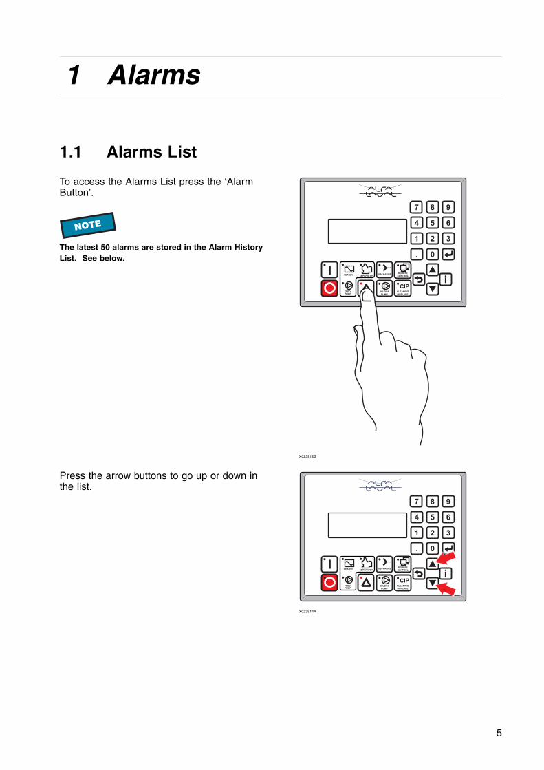
To access the Alarms List press the ‘AlarmButton’.
NOTE
The latest 50 alarms are stored in the Alarm HistoryList. See below.
9
6
3
8
2
0
7
4
1
.
i
5
SLUDGE
PUMP
CLEANING
IN PLACE
REMOTE
CONTROL
CIP
DISCHARGE
FEED
PUMP
HEATERSEPARATOR
X023912B
Press the arrow buttons to go up or down inthe list.
9
6
3
8
2
0
7
4
1
.
i
5
SLUDGE
PUMP
CLEANING
IN PLACE
REMOTE
CONTROL
CIP
DISCHARGE
FEED
PUMP
HEATERSEPARATOR
X023914A
5
1 Alarms
For each item in the list you can press the‘Information’ button for help and information.Press the ‘Information’ button again to return toyour previous position.
You can also acknowledge and/or reset thisalarm.
9
6
3
8
2
0
7
4
1
.
i
5
SLUDGE
PUMP
CLEANING
IN PLACE
REMOTE
CONTROL
CIP
DISCHARGE
FEED
PUMP
HEATERSEPARATOR
X023915A
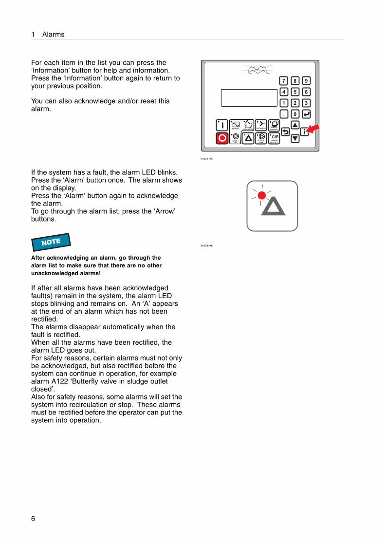
If the system has a fault, the alarm LED blinks.Press the ‘Alarm’ button once. The alarm showson the display.Press the ‘Alarm’ button again to acknowledgethe alarm.To go through the alarm list, press the ‘Arrow’buttons.
NOTE
After acknowledging an alarm, go through thealarm list to make sure that there are no otherunacknowledged alarms!
If after all alarms have been acknowledgedfault(s) remain in the system, the alarm LEDstops blinking and remains on. An ‘A’ appearsat the end of an alarm which has not beenrectified.The alarms disappear automatically when thefault is rectified.When all the alarms have been rectified, thealarm LED goes out.For safety reasons, certain alarms must not onlybe acknowledged, but also rectified before thesystem can continue in operation, for examplealarm A122 ‘Butterfly valve in sludge outletclosed’.Also for safety reasons, some alarms will set thesystem into recirculation or stop. These alarmsmust be rectified before the operator can put thesystem into operation.
X023919A
6
1 Alarms
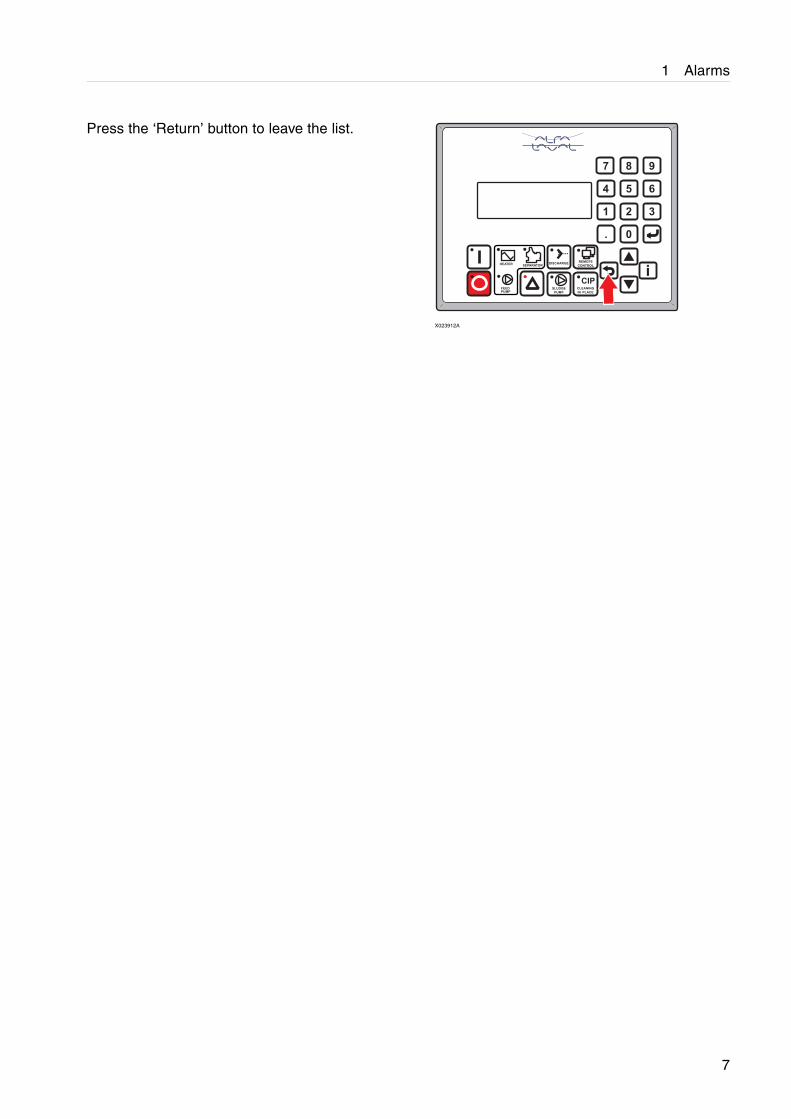
Press the ‘Return’ button to leave the list.
9
6
3
8
2
0
7
4
1
.
i
5
SLUDGE
PUMP
CLEANING
IN PLACE
REMOTE
CONTROL
CIP
DISCHARGE
FEED
PUMP
HEATERSEPARATOR
X023912A
7
1 Alarms
1.2 Alarm History List
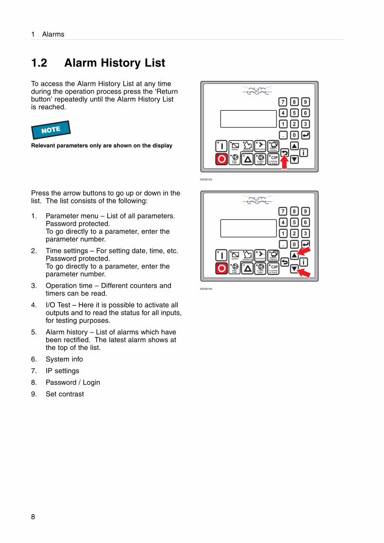
To access the Alarm History List at any timeduring the operation process press the ‘Returnbutton’ repeatedly until the Alarm History Listis reached.
NOTE
Relevant parameters only are shown on the display
9
6
3
8
2
0
7
4
1
.
i
5
SLUDGE
PUMP
CLEANING
IN PLACE
REMOTE
CONTROL
CIP
DISCHARGE
FEED
PUMP
HEATERSEPARATOR
X023912A
Press the arrow buttons to go up or down in thelist. The list consists of the following:
1. Parameter menu – List of all parameters.Password protected.To go directly to a parameter, enter theparameter number.
2. Time settings – For setting date, time, etc.Password protected.To go directly to a parameter, enter theparameter number.
3. Operation time – Different counters andtimers can be read.
4. I/O Test – Here it is possible to activate alloutputs and to read the status for all inputs,for testing purposes.
5. Alarm history – List of alarms which havebeen rectified. The latest alarm shows atthe top of the list.
6. System info
7. IP settings
8. Password / Login
9. Set contrast
9
6
3
8
2
0
7
4
1
.
i
5
SLUDGE
PUMP
CLEANING
IN PLACE
REMOTE
CONTROL
CIP
DISCHARGE
FEED
PUMP
HEATERSEPARATOR
X023914A
8
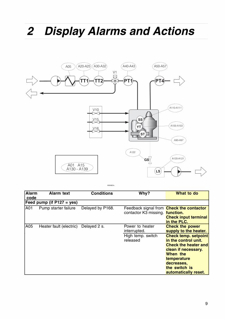
2 Display Alarms and Actions
T 2T P 1T
A05 A30-A32
T 1T
A20-A25
V1
V10
V15
V16
A40-A43
PT4
A50-A57
SS
A110-A111
YTA100-A103
ST
A90-A97
LS
A120-A121
A122
GS
A01 A15
A130 - A139
X024967a
Alarmcode
Alarm text Conditions Why? What to do
Feed pump (if P127 = yes)A01 Pump starter failure Delayed by P168. Feedback signal from
contactor K3 missing.Check the contactorfunction.Check input terminalin the PLC.
Power to heaterinterrupted.
Check the powersupply to the heater.
A05 Heater fault (electric) Delayed 2 s.
High temp. switchreleased
Check temp. setpointin the control unit.Check the heater andclean if necessary.When thetemperaturedecreases,the switch isautomatically reset.
9
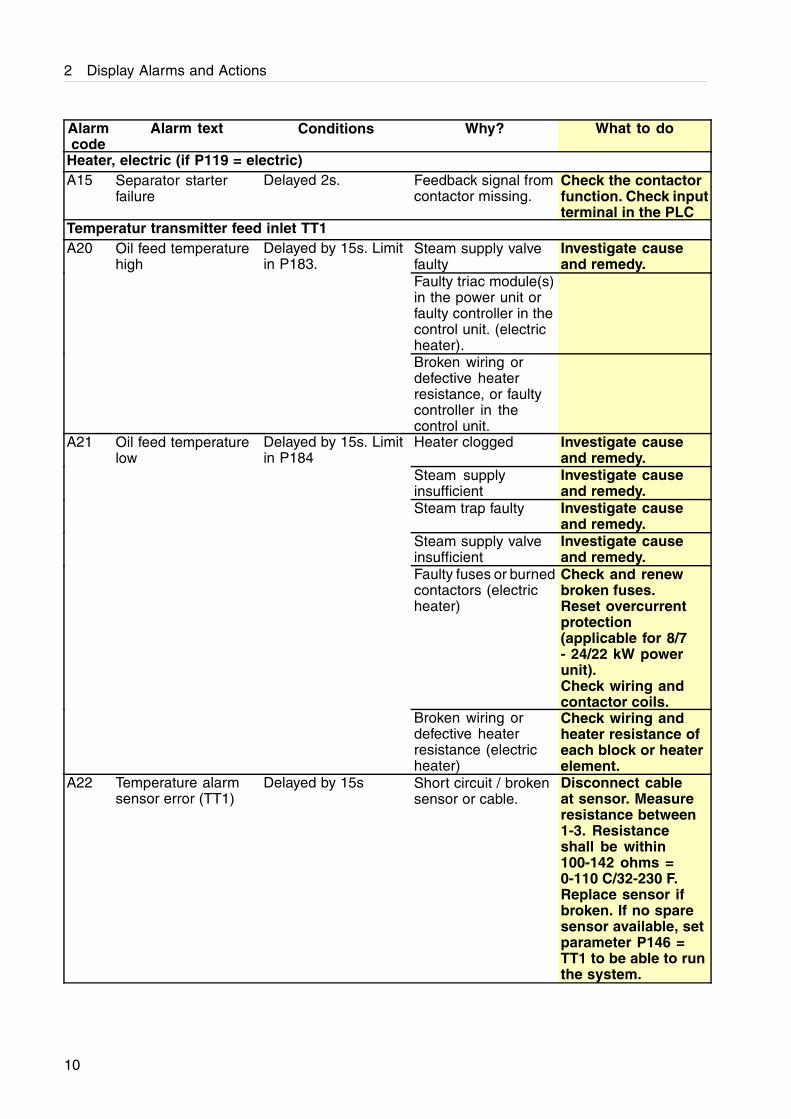
2 Display Alarms and Actions
Alarmcode
Alarm text Conditions Why? What to do
Heater, electric (if P119 = electric)A15 Separator starter
failureDelayed 2s. Feedback signal from
contactor missing.Check the contactorfunction. Check inputterminal in the PLC
Temperatur transmitter feed inlet TT1Steam supply valvefaulty
Investigate causeand remedy.
Faulty triac module(s)in the power unit orfaulty controller in thecontrol unit. (electricheater).
A20 Oil feed temperaturehigh
Delayed by 15s. Limitin P183.
Broken wiring ordefective heaterresistance, or faultycontroller in thecontrol unit.Heater clogged Investigate cause
and remedy.Steam supplyinsufficient
Investigate causeand remedy.
Steam trap faulty Investigate causeand remedy.
Steam supply valveinsufficient
Investigate causeand remedy.
Faulty fuses or burnedcontactors (electricheater)
Check and renewbroken fuses.Reset overcurrentprotection(applicable for 8/7- 24/22 kW powerunit).Check wiring andcontactor coils.
A21 Oil feed temperaturelow
Delayed by 15s. Limitin P184
Broken wiring ordefective heaterresistance (electricheater)
Check wiring andheater resistance ofeach block or heaterelement.
A22 Temperature alarmsensor error (TT1)
Delayed by 15s Short circuit / brokensensor or cable.
Disconnect cableat sensor. Measureresistance between1-3. Resistanceshall be within100-142 ohms =0-110 C/32-230 F.Replace sensor ifbroken. If no sparesensor available, setparameter P146 =TT1 to be able to runthe system.
10
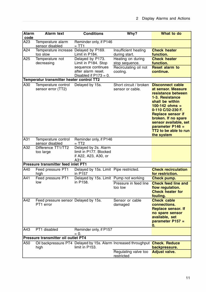
2 Display Alarms and Actions
Alarmcode
Alarm text Conditions Why? What to do
A23 Temperature alarmsensor disabled
Reminder only, if P146= TT1
A24 Temperature increasetoo slow
Delayed by P169.Limit in P184.
Insufficient heatingduring start.
Check heaterfunction.
Heating on duringstop sequence.
Check heaterfunction.
A25 Temperature notdecreasing
Delayed by P173.Limit in P184. Stopsequence continuesafter alarm reset.Disabled if P173 = 0.
Recirculating oil notcooling.
Reset alarm tocontinue.
Temperatur transmitter heater control TT2A30 Temperature control
sensor error (TT2)Delayed by 15s. Short circuit / broken
sensor or cable.Disconnect cableat sensor. Measureresistance between1-3. Resistanceshall be within100-142 ohms =0-110 C/32-230 F.Replace sensor ifbroken. If no sparesensor available, setparameter P146 =TT2 to be able to runthe system
A31 Temperature controlsensor disabled
Reminder only, if P146= TT2
A32 Difference TT1/TT2too large
Delayed by 2s. Alarmlimit in P177. Blockedif A22, A23, A30, orA31
Pressure transmitter feed inlet PT1A40 Feed pressure PT1
highDelayed by 15s. Limitin P157
Pipe restricted. Check recirculationfor restriction.
Pump not working Check pump.A41 Feed pressure PT1low
Delayed by 15s. Limitin P158. Pressure in feed line
too lowCheck feed line andflow regulation.Check heater forfouling.
A42 Feed pressure sensorPT1 error
Delayed by 15s. Sensor or cabledamaged
Check cableconnections.Replace sensor. Ifno spare sensoravailable, setparameter P157 =0.
A43 PT1 disabled Reminder only, if P157= 0.
Pressure transmitter oil outlet PT4A50 Oil backpressure PT4
highDelayed by 15s. Alarmlimit in P153.
Increased throughput Check. Reducebackpressure.
Regulating valve toorestricted
Adjust valve.
11
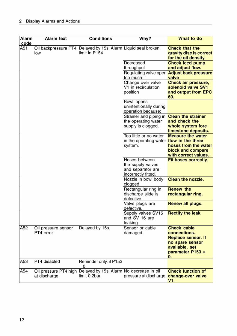
2 Display Alarms and Actions
Alarmcode
Alarm text Conditions Why? What to do
A51 Oil backpressure PT4low
Delayed by 15s. Alarmlimit in P154.
Liquid seal broken Check that thegravity disc is correctfor the oil density.
Decreasedthroughput
Check feed pumpand adjust flow.
Regulating valve opentoo much
Adjust back pressurevalve
Change over valveV1 in recirculationposition
Check air pressure,solenoid valve SV1and output from EPC60.
Bowl opensunintentionally duringoperation because:Strainer and piping inthe operating watersupply is clogged.
Clean the strainerand check thewhole system forelimestone deposits.
Too little or no waterin the operating watersystem.
Measure the waterflow in the threehoses from the waterblock and comparewith correct values.
Hoses betweenthe supply valvesand separator areincorrectly fitted.
Fit hoses correctly.
Nozzle in bowl bodyclogged
Clean the nozzle.
Rectangular ring indischarge slide isdefective.
Renew therectangular ring.
Valve plugs aredefective.
Renew all plugs.
Supply valves SV15and SV 16 areleaking.
Rectify the leak.
A52 Oil pressure sensorPT4 error
Delayed by 15s. Sensor or cabledamaged.
Check cableconnections.Replace sensor. Ifno spare sensoravailable, setparameter P153 =0.
A53 PT4 disabled Reminder only, if P153= 0.
A54 Oil pressure PT4 highat discharge
Delayed by 15s. Alarmlimit 0.2bar.
No decrease in oilpressure at discharge.
Check function ofchange-over valveV1.
12
2 Display Alarms and Actions
Alarmcode
Alarm text Conditions Why? What to do
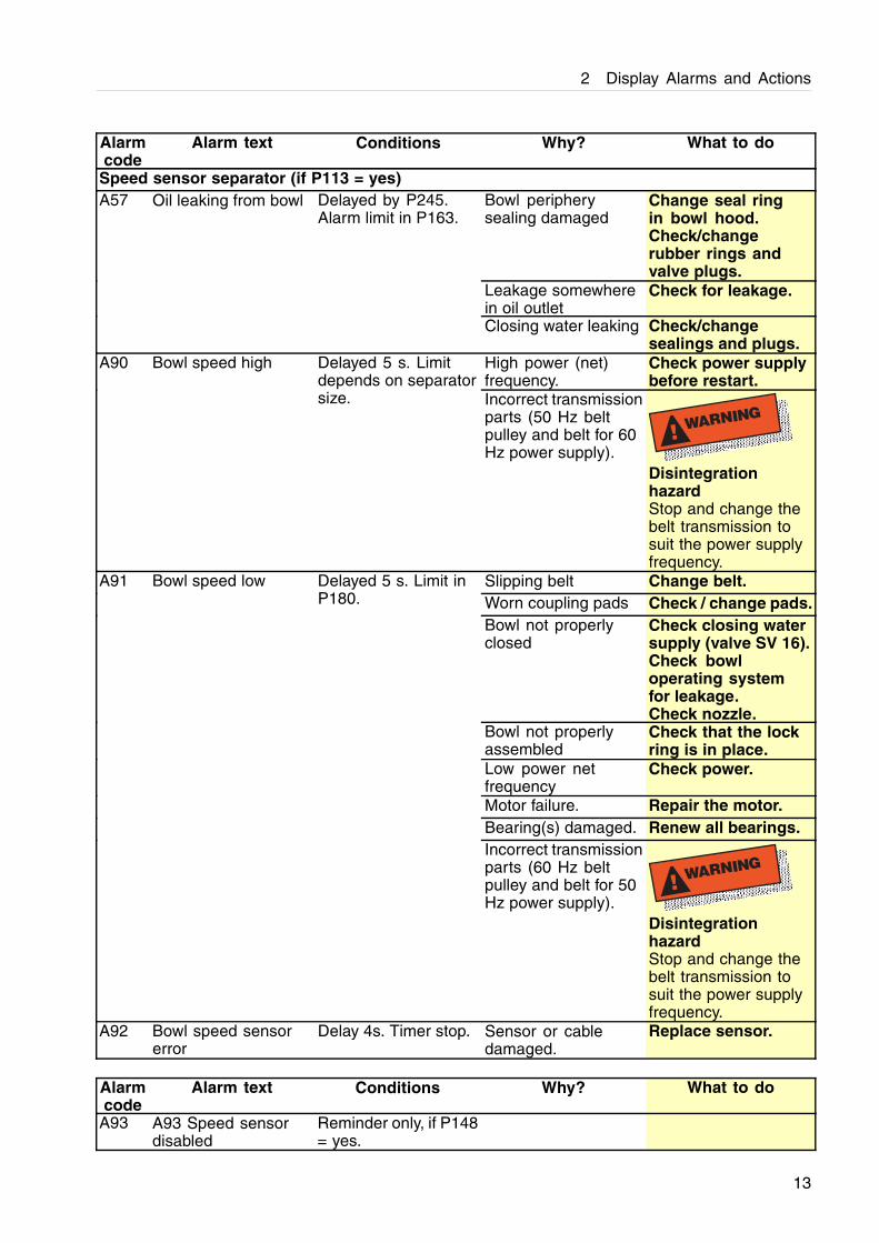
Speed sensor separator (if P113 = yes)Bowl peripherysealing damaged
Change seal ringin bowl hood.Check/changerubber rings andvalve plugs.
Leakage somewherein oil outlet
Check for leakage.
A57 Oil leaking from bowl Delayed by P245.Alarm limit in P163.
Closing water leaking Check/changesealings and plugs.
High power (net)frequency.
Check power supplybefore restart.
A90 Bowl speed high Delayed 5 s. Limitdepends on separatorsize. Incorrect transmission
parts (50 Hz beltpulley and belt for 60Hz power supply).
! WARNING
DisintegrationhazardStop and change thebelt transmission tosuit the power supplyfrequency.
Slipping belt Change belt.Worn coupling pads Check / change pads.Bowl not properlyclosed
Check closing watersupply (valve SV 16).Check bowloperating systemfor leakage.Check nozzle.
Bowl not properlyassembled
Check that the lockring is in place.
Low power netfrequency
Check power.
Motor failure. Repair the motor.Bearing(s) damaged. Renew all bearings.
A91 Bowl speed low Delayed 5 s. Limit inP180.
Incorrect transmissionparts (60 Hz beltpulley and belt for 50Hz power supply).
! WARNING
DisintegrationhazardStop and change thebelt transmission tosuit the power supplyfrequency.
A92 Bowl speed sensorerror
Delay 4s. Timer stop. Sensor or cabledamaged.
Replace sensor.
Alarmcode
Alarm text Conditions Why? What to do
A93 A93 Speed sensordisabled
Reminder only, if P148= yes.
13
2 Display Alarms and Actions
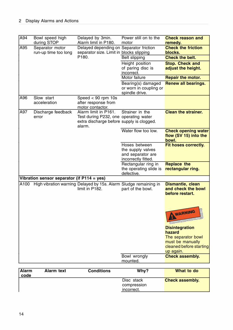
A94 Bowl speed highduring STOP
Delayed by 3min.Alarm limit in P180.
Power still on to themotor
Check reason andremedy.
Separator frictionblocks slipping
Check the frictionblocks.
Belt slipping Check the belt.Height positionof paring disc isincorrect.
Stop. Check andadjust the height.
Motor failure Repair the motor.
A95 Separator motorrun-up time too long
Delayed depending onseparator size. Limit inP180.
Bearing(s) damagedor worn in coupling orspindle drive.
Renew all bearings.
A96 Slow startacceleration
Speed < 90 rpm 10safter response frommotor contactor.
A97 Discharge feedbackerror
Alarm limit in P161.Test during P232, oneextra discharge beforealarm.
Strainer in theoperating watersupply is clogged.
Clean the strainer.
Water flow too low. Check opening waterflow (SV 15) into thebowl.
Hoses betweenthe supply valvesand separator areincorrectly fitted.
Fit hoses correctly.
Rectangular ring inthe operating slide isdefective.
Replace therectangular ring.
Vibration sensor separator (if P114 = yes)Sludge remaining inpart of the bowl.
Dismantle, cleanand check the bowlbefore restart.
! WARNING
DisintegrationhazardThe separator bowlmust be manuallycleaned before startingup again.
A100 High vibration warning Delayed by 15s. Alarmlimit in P182.
Bowl wronglymounted.
Check assembly.
Alarmcode
Alarm text Conditions Why? What to do
Disc stackcompressionincorrect.
Check assembly.
14
2 Display Alarms and Actions
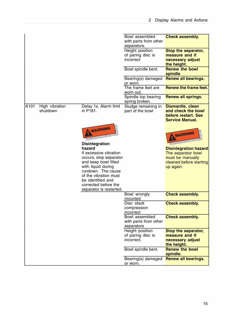
Bowl assembledwith parts from otherseparators.
Check assembly.
Height positionof paring disc isincorrect
Stop the separator,measure and ifnecessary adjustthe height.
Bowl spindle bent. Renew the bowlspindle
Bearing(s) damagedor worn.
Renew all bearings.
The frame feet areworn out.
Renew the frame feet.
Spindle top bearingspring broken.
Renew all springs.
Delay 1s. Alarm limitin P181.
! WARNING
DisintegrationhazardIf excessive vibrationoccurs, stop separatorand keep bowl filledwith liquid duringrundown. The causeof the vibration mustbe identified andcorrected before theseparator is restarted.
Sludge remaining inpart of the bowl
Dismantle, cleanand check the bowlbefore restart. SeeService Manual.
! WARNING
Disintegration hazardThe separator bowlmust be manuallycleaned before startingup again.
Bowl wronglymounted
Check assembly.
Disc stackcompressionincorrect
Check assembly.
Bowl assembledwith parts from otherseparators
Check assembly.
Height positionof paring disc isincorrect.
Stop the separator,measure and ifnecessary adjustthe height.
Bowl spindle bent. Renew the bowlspindle.
A101 High vibrationshutdown
Bearing(s) damagedor worn.
Renew all bearings.
15
2 Display Alarms and Actions
Alarmcode
Alarm text Conditions Why? What to do
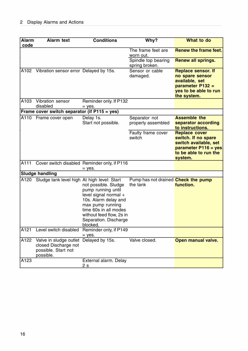
The frame feet areworn out.
Renew the frame feet.
Spindle top bearingspring broken.
Renew all springs.
A102 Vibration sensor error Delayed by 15s. Sensor or cabledamaged.
Replace sensor. Ifno spare sensoravailable, setparameter P132 =yes to be able to runthe system.
A103 Vibration sensordisabled
Reminder only. If P132= yes.
Frame cover switch separator (if P115 = yes)Separator notproperly assembled
Assemble theseparator accordingto instructions.
A110 Frame cover open Delay 1s.Start not possible.
Faulty frame coverswitch
Replace coverswitch. If no spareswitch available, setparameter P116 = yesto be able to run thesystem.
A111 Cover switch disabled Reminder only, if P116= yes.
Sludge handlingA120 Sludge tank level high At high level: Start
not possible. Sludgepump running untillevel signal normal +10s. Alarm delay andmax pump runningtime 60s in all modeswithout feed flow, 2s inSeparation. Dischargeblocked.
Pump has not drainedthe tank
Check the pumpfunction.
A121 Level switch disabled Reminder only, if P149= yes.
A122 Valve in sludge outletclosed Discharge notpossible. Start notpossible.
Delayed by 15s. Valve closed. Open manual valve.
A123 External alarm. Delay2 s
16
2 Display Alarms and Actions
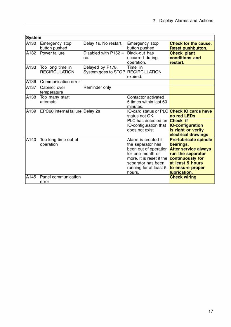
SystemA130 Emergency stop
button pushedDelay 1s. No restart. Emergency stop
button pushedCheck for the cause.Reset pushbutton.
A132 Power failure Disabled with P152 =no.
Black-out hasoccurred duringoperation.
Check plantconditions andrestart.
A133 Too long time inRECIRCULATION
Delayed by P178.System goes to STOP.
Time inRECIRCULATIONexpired.
A136 Communication errorA137 Cabinet over
temperatureReminder only
A138 Too many startattempts
Contactor activated5 times within last 60minutes.
A139 EPC60 internal failure Delay 2s IO-card status or PLCstatus not OK
Check IO cards haveno red LEDs
PLC has detected anIO-configuration thatdoes not exist
Check ifIO-configurationis right or verifyelectrical drawings
A140 Too long time out ofoperation
Alarm is created ifthe separator hasbeen out of operationfor one month ormore. It is reset if theseparator has beenrunning for at least 5hours.
Pre-lubricate spindlebearings.After service alwaysrun the separatorcontinuously forat least 5 hoursto ensure properlubrication.
A145 Panel communicationerror
Check wiring
17

2 Display Alarms and Actions

3 EPC 60 Control panel
Fault RemedyBlack screen Press and hold Enter button and adjust contrast with
up and down button.This can be done regardless of which page iscurrently displayed.
19


![Car Alarms & Smoke Alarms [Monitorama]](https://img.pdfslide.net/doc/110x75/54b6cdf94a7959d84d8b45a5/car-alarms-smoke-alarms-monitorama.jpg)