Embed Size (px)
Citation preview
~ 1 ~
International Journal of Advances in Electrical Engineering 2021; 2(1): 01-12
E-ISSN: 2708-4582
P-ISSN: 2708-4574
IJAEE 2021; 2(1): 01-12
© 2021 IJAEE
www.electricaltechjournal.com
Received: 03-11-2020
Accepted: 05-12-2020
B Thirumala Rao
PG Scholar, EEE Department,
Koneru Lakshmaiah
Education Foundation,
Vaddeswaram, Guntur,
Andhra Pradesh, India
Dr. B Jyothi
EEE Department,
Koneru Lakshmaiah
Education Foundation,
Vaddeswaram, Guntur,
Andhra Pradesh, India
P Bhavana
EEE Department, SRKIT,
Vijayawada, Andhra Pradesh,
India
M Sai Krishna Reddy
EEE Department, Koneru
Lakshmaiah Education
Foundation, Vaddeswaram,
Guntur, Andhra Pradesh,
India
Corresponding Author:
B Thirumala Rao
PG Scholar, EEE Department,
Koneru Lakshmaiah
Education Foundation,
Vaddeswaram, Guntur,
Andhra Pradesh, India
Implementation of modified SEPIC converter for
renewable energy based DC micro grids
B Thirumala Rao, Dr. B Jyothi, P Bhavana and M Sai Krishna Reddy
Abstract The implementation of PV-driven DC micro grids technology is inexpensive, harmless, simple,
flexible, and also energy effective to the end-users. Here the proposed Modified SEPIC converter
(MSC) is designed based on the traditional SEPIC with a boost-up module. While related to the
conventional or traditional SEPIC converter, the proposed MSC produces higher voltage gain and
continuous current to the DC micro grids. Moreover, this MSC is operated with a single controlled
switch. Here MSC with PV system-based DC micro grids are implemented to effectively satisfy DC
loads requirements and moreover entire this work is carried out in PSIM software.
Keywords: MSC, PV systems, P & O MPPT technique, DC micro grids, half-bridge bidirectional DC-
DC converters, DC loads
1. Introduction In previous days power generation is done by the conventional energy sources and fossil
fuels to generate electricity to the end users. But day by day fossil fuels and coal reserves are
falling due to the over usage by human beings to fulfil their needs in the area of transport
division, electrical energy generation and etc. Here the problem related with these
conventional energy sources such as fossil fuels, coal energy, nuclear energy and etc. can
generate a harmful gases (SO2, and NO2) and carbon emissions (CO and CO2) in atmosphere,
when these energy sources are utilized for electrical energy generation. This SO2, CO2
andNO2 gases are emitted in atmosphere with large quantities can lead to developing a global
warming and greenhouse effect in nature [1]. In 2013, Sinopec pipeline blasted in Shandong
Area in China, taking away valuable lives of 55 people. The firms of coal, natural gas, and
oil are responsible for these severe threats. So, to avoid these serious problems government
officials are looking towards for the alternative energy sources [2, 3].
Now-a-days all research persons are looking towards the alternative energy sources to
generate electricity without producing any carbon emissions, global warming and etc. Based
on the researcher’s point of view renewable energy sources are referred as an alternative
energy sources to produce electricity to meet the loads without producing any harmful gases.
In renewable or non-conventional energy sources like wind and solar energies are the major
renewable energy sources for the distributed energy systems due to their availability in
nature. While other non-conventional energy sources are biomass, tidal, geothermal energy
sources exist in nature in particular regional sectors. But solar and wind energies are
abundant in nature and available all regional sectors. Especially, solar and wind energy
sources are gives maximum efficiency and reliability when compared with other non-
conventional energy sources. More over all research workers are focuses on these two
renewable energy sectors integrated to the AC and DC grids.
Normally, in the perception of the micro grid, DC micro grids are implemented easily due to
the availability of distributed energy sources like non-conventional energy sources (PV cells,
Fuel cells), energy storing devices like batteries, super capacitors and etc. can store electrical
energy in the form of DC. So that’s the reason nowadays all research people are turning
towards the implementation of DC micro grids with PV cells, Batteries and etc. for satisfying
the DC load demand.
Another important feature regarding the DC micro grid is one can easily implement a DC
micro grid with one or two DC-DC converters but AC micro grids require a larger number of
both DC-DC, DC-AC converters. As a result, DC micro grids are required less expensive
materials and also these grids provide an improved efficiency compared with the AC micro

International Journal of Advances in Electrical Engineering www.electricaltechjournal.com
~ 2 ~
grids. Similarly, DC is more efficient due to its simple
topology; the absence of frequency, harmonic distortion and
reactive power and also DC micro grids don’t bother about
the grid synchronization with the network. But, in AC micro
grids grid synchronization with a network plays a major
role. Thus, one can easily design a control structure for DC
micro grids over AC micro grids [4, 5, 6].
Fig 1: Overview of DC micro grid
Thus, the paper focus on the application of DC micro grids
with DC-DC converters for effective driven of the DC
loads. So, solar energy is preferred as input resource for DC
micro grids. Especially in solar energy, PV panels based
solar systems are giving electricity directly from the sun
light and these PV systems are requires less space, low cost
and gives maximum efficiency to the DC micro grids when
compared with the solar thermal collectors. So, most of the
research work is carried out with the PV systems based DC
micro grids for satisfying the DC load demand.
In general solar PV panels generate low output voltage to
the DC micro grids. Then this low DC voltage coming from
the PV panels can’t properly drive a high voltage DC
applications requirement in DC micro grids. Generally, PV
cells are connected in parallel and series combination to
generate more amount of current and voltage to the PV
module. Then several such modules are connected for any
application to get preferred volume of voltage and current to
the end users. But this is an inefficient way to generate a
higher DC voltage and DC current due to the necessity of 2,
3 …N number of series and parallel connected PV panels
and also size of this whole system is increased. Due to this
reason research towards the integration of DC-DC
converters with PV panels based DC micro grids is
implemented as up-to-date [2].
Solar PV panels are applicable in the field of a both AC and
DC load applications. In DC micro grids, solar PV panels
are linked to the DC loads with the help of isolated or non-
isolated DC-DC converters to attain high voltage gain and
continuous output current to the DC micro grids. Generally
DC micro grids are connected to the isolated or non-isolated
DC-DC converters with high voltage gain to produces a
high voltage on the output side. With the help of a HF
transformer by changing its turn ratio one can easily get a
boost up voltage at output side in isolated DC-DC
converters [7, 8]. But, these isolated DC-DC converters
suffering from the problems like that voltage ripples in input
current at primary side of high frequency transformer and
secondary side of the high-frequency transformer of these
converters can produce high voltage stress and leakage
currents. Furthermore, very large size high-frequency
transformers are placed in these isolated converters to
properly produce an output voltage in the boost module etc. [9].
In earlier day’s traditional buck-boost, SEPIC, CUK type
non-isolated DC-DC converters with maximum duty ratio
technique can be used for high voltage applications. But
these conventional DC-DC converters are operated at
maximum duty ratio [approximately ranges in 0.85 to 0.95]
can reduces the efficiency and disturbs the functionality of
the converter. In recent times, several DC-DC converters
with high voltage gain can be used with the application of
passive elements to boost up steps [10, 11].
As a final point, with a compact size, high efficiency,
continuous current and etc. are the requirements of
economic considerations for DC-DC converters, that is the
reason all researchers are utilizing the non-isolated DC-DC
converters as unimpeachable key for PV systems, DC micro
grids etc. Several voltage-boosting methods as like coupled
inductor cascading of converters are attaining high output
voltage of non-isolated DC-DC converter are addressed in [12-15].
The non-isolated DC-DC converters with coupled inductors
can control the output voltage based on the inductor coil’s
turn’s ratio alteration. This coupled inductor’s leakage
inductance is inflexible which produces ripples in power
switch current, reduces the current spike in coupled inductor
and these converters requires a clamping circuit.
In cascaded non-isolated DC-DC converters, the Quadratic
Boost Converters (QBC) is an example of series-connected
non-isolated DC-DC converters and these produce output
voltage with boosting module in a quadratic manner but this
QBC produce more voltage stress on the power switch and
on the diode also. The high voltage multiplier 2nd order
boost non-isolated DC-DC converter is deliberated in [16]. In
this converter’s output voltage is influenced by the number
of voltage multipliers and on-duty ratio. On the other hand,
this converter generates an output voltage in less magnitude.
However, this converter is equipped with number of voltage
multipliers.
An active network-based switched-capacitor non-isolated
DC-DC converter with high gain is presented in [17]. This
converter attains high gain with poor regulation. Moreover
this converter produces an input current in discontinues way
which verifies the least use of the input sources. The [17-20]
non-isolated DC-DC converters operate with low voltage
stress across diodes and switches. Then low voltage stress
across switching mechanisms can be accepted to decrease
the conduction loss and cost of the whole system. These
converters have a wide regulation series, small component
stresses, less significant output ripple, adaptable gain
extension, and high-level efficiency. But, these Converters
attain high gain with poor regulation and pulsating current.
This converter controlled with two switches and those make
the difficulty in the controller scheme and disturb the
efficiency at the load end.
At this time the proposed MSC [21] can overcome the
problems in the non-isolated and isolated DC-DC converters
addressed in [7-20]. MSC can’t produce any voltage or current
ripples even if this converter taking DC voltage with some
distortions, because MSC having a resonant elements such
as inductor, capacitor across the switch to eliminate switch
stress and unwanted disturbances [22]. But MSC overcome

International Journal of Advances in Electrical Engineering www.electricaltechjournal.com
~ 3 ~
all demerits of above non-isolated DC-DC converters. MSC
have an extreme utilization of resources when it is
connected to input sources. Thus, MSC used as a DC-DC
converter in the Photo Voltaic system based DC micro grids
to generate a maximum efficiency, high voltage gain,
continuous output current to the utility grids.
PV array with MPP is typically an important part of the PV
system. Research fellows develop and implement many
MPPT techniques used for PV arrays to generate maximum
power and transmitting that power to the load to satisfy the
load demand [23]. The techniques vary in sensors required,
complexity, range of effectiveness, convergence speed and
etc.
So many techniques are still exists for the PV system to
generate MPP. The DC-DC converter can effectively utilize
in transmitting MPP from the PV array to the load. Through
regulating the duty cycle of the pulse width modulation
control, the DC-DC converter’s load voltage differs and
obtains the MPP with the input source (PV array) to
transmit the maximum power. Utilizing PV panels without
any controller that can achieve MPPT will frequently result
in unused power. Then to increase the efficiency of the PV
system with an effective MPPT controller is necessary to
maintain the operating point of the PV array at the
maximum power point in all ecological situations.
So to maintain an MPPT of the PV array mandatorily
requires a better MPPT controller with less convergence
time and less complexity in its controller algorithm. For this
solution, researchers develop many MPPT techniques such
as Perturb and Observe (P & O) technique, Hill Climbing
(HC) technique, Incremental Conductance (IC) technique
and etc. But most of the research workers use the P&O
MPPT technique is quite easy, a simple algorithm, and less
complexity associated with the remaining other MPPT
techniques [24].
If in case the PV system can meet the load demand in
partially shaded conditions and in rainy days back up should
be provided to them DC micro grids through battery with a
BDC [Bidirectional DC-DC Converter]. Especially this
paper is focus on the half-bridge BDC is the best BDC in its
performance (voltage gain, switch stress and etc.) [25]. When
compared it with among the [9, 26] BDCs. Here the proposed
BDC is a non-isolated DC-DC converter and this proposed
BDC requires only two switches with three passive elements
(two capacitors, one inductor), moreover this BDCs cost is
low when compared with [9, 26] non-isolated DC-DC
converters.
When the system with a battery and PV array used as input
sources to the DC micro grids can effectively satisfy the DC
loads demand. If the PV system fully satisfies the DC micro
grid system that time the proposed BDC must work in buck
mode to store the DC voltage in a battery. If the PV system
can’t satisfy the DC loads in DC micro grid necessities, in
that time, the proposed BDC can operate in boost mode and
makes the battery to supply a DC voltage to the DC loads
with their requirements in DC micro grids.
Finally, the remaining paper is organized as follows:
section-II, III explains the performance analysis of
Conventional SEPIC converter, and MSC. The importance
of the half-bridge BDC for the PV system based DC micro
grids is addressed in the section IV. Discussion on
simulation outcomes of the MSC, the half-bridge BDC, and
the PV system based DC micro grid with MSC are viewed
in the division of V. At most section-VI concludes this
paper.
2. Conventional SEPIC converter
Conventional or traditional SEPIC converter is also termed
as a single ended primary inductor converter. In general
conventional SEPIC converters normally used in the high-
voltage renewable energy applications. But problem
associated with this converter is listed as follows:
1. This converter produces less voltage gain.
2. This converter generate ripples at output side (load
side) when this converter takes input voltage with some
noise signals.
3. This converter does not properly utilize input resources
in required manner.
The difficulties related with this conventional SEPIC
converter are overcome with the MSC discussed in latter
section. Moreover, conventional SEPIC converter needs
extreme duty ratio point to operate a converter in a boost
mode. So, finally this conventional SEPIC converter is
affects the efficiency and functionality of the system when
this conventional SEPIC converter is operated at maximum
duty ratio. But MSC does not need any maximum duty ratio
point and then this converter operate in boost mode in the
duty ratio of 0.55 to 1 in efficient manner with producing
any unwanted disconcerting signals. The following circuit
diagram of the conventional SEPIC converter normally
operate like a buck-boost DC-DC converter but this
conventional SEPIC converter continuously generate output
current in continuous way.
Fig 2: Circuit diagram of a conventional SEPIC converter
3. Modified SEPIC converter
Fig 3: Circuit diagram of a modified SEPIC converter
In this paper non-isolated Modified SEPIC Converter
(MSC) is existing for high voltage applications (ex: -
renewable energy applications). This MSC containing the
single input-output terminals and derivative by changing the
conventional SEPIC converter as exposed in Fig. 2. & Fig. 3
demonstrations the circuit diagram of the MSC containing 3
International Journal of Advances in Electrical Engineering www.electricaltechjournal.com
~ 4 ~
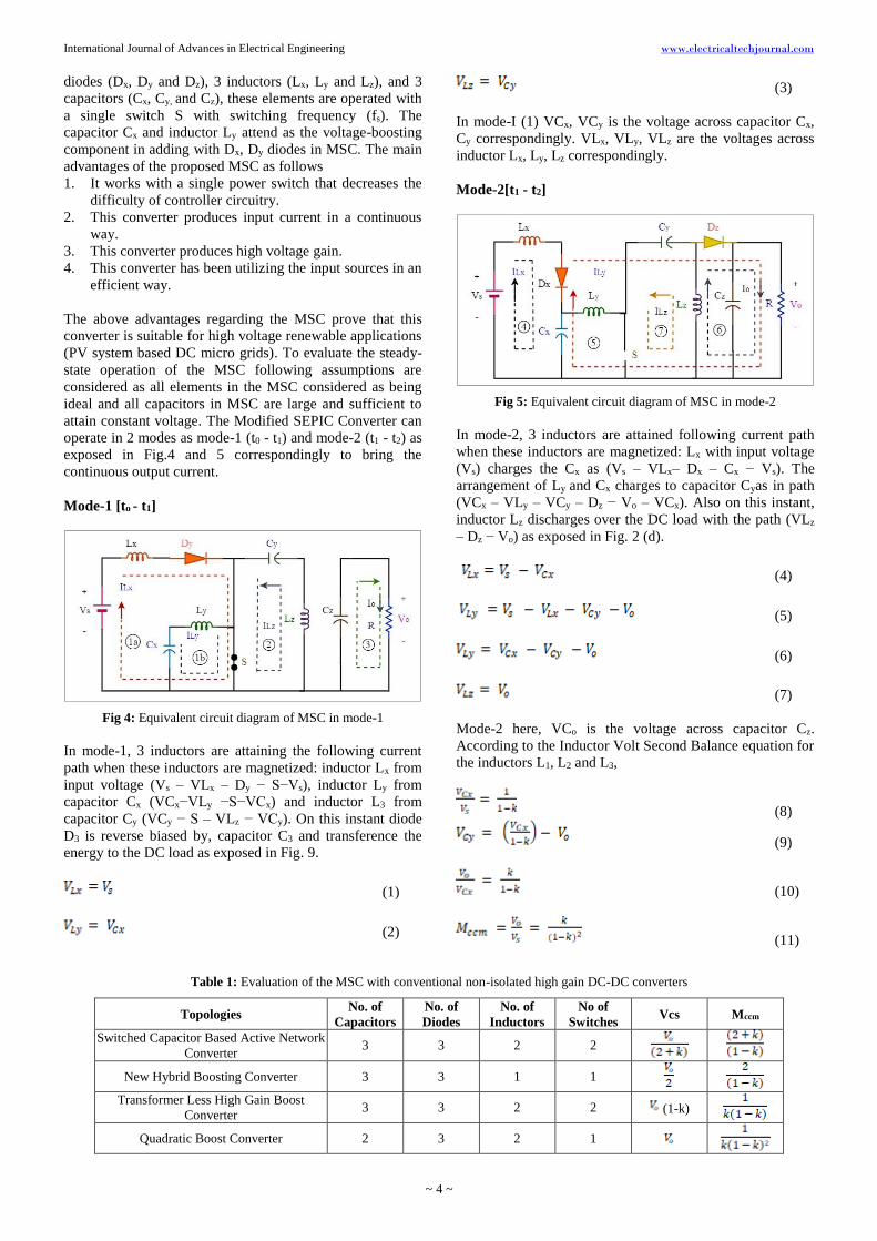
diodes (Dx, Dy and Dz), 3 inductors (Lx, Ly and Lz), and 3
capacitors (Cx, Cy, and Cz), these elements are operated with
a single switch S with switching frequency (fs). The
capacitor Cx and inductor Ly attend as the voltage-boosting
component in adding with Dx, Dy diodes in MSC. The main
advantages of the proposed MSC as follows
1. It works with a single power switch that decreases the
difficulty of controller circuitry.
2. This converter produces input current in a continuous
way.
3. This converter produces high voltage gain.
4. This converter has been utilizing the input sources in an
efficient way.
The above advantages regarding the MSC prove that this
converter is suitable for high voltage renewable applications
(PV system based DC micro grids). To evaluate the steady-
state operation of the MSC following assumptions are
considered as all elements in the MSC considered as being
ideal and all capacitors in MSC are large and sufficient to
attain constant voltage. The Modified SEPIC Converter can
operate in 2 modes as mode-1 (t0 - t1) and mode-2 (t1 - t2) as
exposed in Fig.4 and 5 correspondingly to bring the
continuous output current.
Mode-1 [to - t1]
Fig 4: Equivalent circuit diagram of MSC in mode-1
In mode-1, 3 inductors are attaining the following current
path when these inductors are magnetized: inductor Lx from
input voltage (Vs – VLx – Dy − S−Vs), inductor Ly from
capacitor Cx (VCx−VLy −S−VCx) and inductor L3 from
capacitor Cy (VCy − S – VLz − VCy). On this instant diode
D3 is reverse biased by, capacitor C3 and transference the
energy to the DC load as exposed in Fig. 9.
(1)
(2)
(3)
In mode-I (1) VCx, VCy is the voltage across capacitor Cx,
Cy correspondingly. VLx, VLy, VLz are the voltages across
inductor Lx, Ly, Lz correspondingly.
Mode-2[t1 - t2]
Fig 5: Equivalent circuit diagram of MSC in mode-2
In mode-2, 3 inductors are attained following current path
when these inductors are magnetized: Lx with input voltage
(Vs) charges the Cx as (Vs – VLx– Dx – Cx − Vs). The
arrangement of Ly and Cx charges to capacitor Cyas in path
(VCx – VLy – VCy – Dz − Vo – VCx). Also on this instant,
inductor Lz discharges over the DC load with the path (VLz
– Dz − Vo) as exposed in Fig. 2 (d).
(4)
(5)
(6)
(7)
Mode-2 here, VCo is the voltage across capacitor Cz.
According to the Inductor Volt Second Balance equation for
the inductors L1, L2 and L3,
(8)
(9)
(10)
(11)
Table 1: Evaluation of the MSC with conventional non-isolated high gain DC-DC converters
Topologies No. of
Capacitors
No. of
Diodes
No. of
Inductors
No of
Switches Vcs Mccm
Switched Capacitor Based Active Network
Converter 3 3 2 2
New Hybrid Boosting Converter 3 3 1 1
Transformer Less High Gain Boost
Converter 3 3 2 2 (1-k)
Quadratic Boost Converter 2 3 2 1

International Journal of Advances in Electrical Engineering www.electricaltechjournal.com
~ 5 ~
Modified SEPIC Converter 3 3 3 1
From Table 1, comparing performance parameters of MSC
with all the other converters, it reduces the voltage stress on
switch is almost negligible and moreover generates high
voltage gain with a single controlled switch makes this
converter is preferable high voltage non-conservative
energy applications. Where, Vcs is a voltage across the
switch, and Mccm is a voltage gain.
From the above table, MSC has a wide range of voltage gain
comparing with the other non-isolated DC-DC converters.
So, this feature makes the MSC can applicable in DC micro
grids.
Table 2: Voltage gain of non-isolated dc-dc converters
Topologies Voltage gain (Mccm) when K is varied
K = 0.6 K = 0.7 K = 0.8 K = 0.9
Switched Capacitor Based Active Network Converter 6.5 9 14 29
New Hybrid Boosting Converter 5 6.67 10 20
Transformer Less High Gain Boost Converter 4.1 4.7 6.25 11.11
Quadratic Boost Converter 6.25 11.11 25 100
Modified SEPIC Converter 3.75 7.78 20 90
From above analysis it leads to conclude that QBC and
MSC are almost all similarly produces a maximum voltage
gain.
4. Half-bridge BDC A non-isolated BDC’s are essentially understood by the
addition of a diode and an anti-parallel diode to the switch
of the uni-directional converter is connected with a
controllable power switch. Basically, buck, boost, buck-
boost, SEPIC, CUK DC-DC converters are makes some
non-isolated BDC’s when the diode in the above DC-DC
converters is interchanged with a controllable power switch.
Based on the voltage boosting methods, non-isolated BDC’s
whereas interleaved multilevel, switched capacitor, etc.
Table 3: Evaluation of the half-bridge BDC with conventional non-isolated BDC’S [6]
Topology in bidirectional
DC-DC converters
Voltage conversion ratio
in buck mode
Voltage conversion ratio
in boost mode
Number of
switches
Number of passive
components
Half-bridge D 2 3
Inverting bidirectional 2 3
CUK 2 5
SEPIC 2 5
From the above table [6] half-bridge configuration type non-
isolated BDC’s are the most capable, high-proficient, robust
in configuration and also these BDC’s gives the high
voltage gain comparing with the other non-isolated BDC’s.
The non-isolated half-bridge BDC exposed in Fig. 3a is
essentially a combination of a step-down converter and a
step-up converter coupled in anti-parallel [6]. Commonly,
this BDC can work in both synchronous boost and buck
modes for power flow in both forward and reverse
directions. The working operation of this BDC can be
described in 2 modes as follows. When power switch P is
turned on with the help of a required duty ratio control the
operation of this BDC viewed in a forward step-down mode.
When Q is turned on then P is turns off with the help of a
proper controlling duty ratio this BDC can undergo a
backward step-up operation.
Fig 6: Circuit diagram of the half-bridge BDC
Fig. 6 shows the circuit diagram of the half bridge BDC.
This BDC requires only two switches with three passive
elements (one inductor and two capacitors). While
comparing this BDC with conventional BDC’s, this BDC
has wide voltage gain especially in boost mode, cost of this
BDC is less and also this BDC generate continuous output
current without ripples. Generally this converter operates in
two modes buck mode and boost mode.
5. Simulation results and Discussion
Fig 7: Block diagram of integration of MSC with PV system based
DC micro grid
By based on the block diagram of this paper is consisting of
two input sources namely as PV source and battery with half
bridge BDC, here DC micro grid consists a DC loads. These

International Journal of Advances in Electrical Engineering www.electricaltechjournal.com
~ 6 ~
blocks are connected to the MSC. MSC is probably
produces an effective DC voltage and current to the DC
loads in DC micro grids from PV source. If in case partially
shaded conditions are happened PV panels doesn’t supply
voltage how much required by the DC micro grid. For back
up protection and to balance the supply voltage and currents
with load voltage and currents, BDC with battery is
required. Here half-bridge BDC is used and supply voltage
to the DC loads if in case PV doesn’t satisfy the amount of
voltage required by the DC loads.
A. Simulation results of the MSC Generally MSC can produce wide voltage gain with continuous output current. Moreover this MSC always uses the resources in maximum level. Then MSC is widely produce voltage gain with better efficiency. Usually, this MSC is effectively operated with a fixed frequency and variable duty ratio technique is widely used PWM technique to effectively generate a gate voltage to the power switch. So, this MSC is effectively simulated in PSIM software and easily generate an output voltage at greater voltage gain with preferred output current required by the DC load. Here this MSC PSIM results are obtained without producing ripple content in its output voltage and current. So, this MSC is well suited for DC micro grids and PV system applications. But conventional non-isolated DC-DC converters produce ripples in the percentage of 0.1-0.5%. But MSC produces ripple content in the percentage of around 0.016. This ripple voltage is a negligible value. That’s the reason this converter effectively produce output voltage without producing any ripple content in output voltage and current.
Fig 8: Waveform of a DC supply voltage Vs of MSC
Fig 9: Waveform of a DC output voltage VO of MSC
Fig 10: Waveform of a DC output current IO of MSC
The above figures describe the supply voltage, output voltage and output current simulation result waveforms of the MSC with values of 24V, 186.3V, 0.5A. These three waveforms are periodically DC in nature. Here MSC can’t generate any ripple content in the output voltage and current. So that’s the reason MSC always generate continuous current to the DC loads.
Fig 11: Waveform of a current ILx flowing in the inductor Lx of MSC
Fig 12: Waveform of a current ILy flowing in the inductor Ly of
MSC
Fig 13: Waveform of a current ILz flowing in the inductor Lz of
MSC
Above figures describes simulation result waveforms of the
inductor Lx, Ly and Lz current regarding the MSC with
values of 4.2 A, 1.4 A and 0.5 A (average) current. In mode-
I, currents flowing in three inductors are increasing with
positive slope and vice versa in mode-II operation.
Fig 14: Waveform of a voltage Vcx across the capacitor cx of
MSC
Fig 15: Waveform of a voltage VCy across the capacitor Cy of MSC
International Journal of Advances in Electrical Engineering www.electricaltechjournal.com
~ 7 ~
Above figures illustrate the simulation results of capacitor
voltages VC1 and VC2 with values of 78.71V, 76.75V. It is
examined that, approximately + 80 V is obtained across the
capacitors C1 and C2. It is analysed that the characteristic
waveforms and this simulation results of capacitor voltages
VC1 and VC2 are matched and steady state in nature.
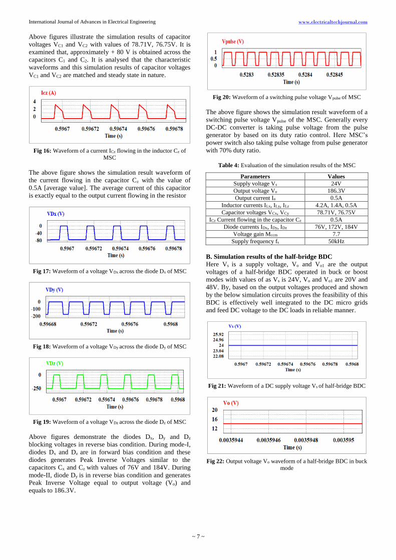
Fig 16: Waveform of a current ICz flowing in the inductor Cz of
MSC
The above figure shows the simulation result waveform of
the current flowing in the capacitor Cz with the value of
0.5A [average value]. The average current of this capacitor
is exactly equal to the output current flowing in the resistor
Fig 17: Waveform of a voltage VDx across the diode Dx of MSC
Fig 18: Waveform of a voltage VDy across the diode Dy of MSC
Fig 19: Waveform of a voltage VDz across the diode Dz of MSC
Above figures demonstrate the diodes Dx, Dy and Dz
blocking voltages in reverse bias condition. During mode-I,
diodes Dx and Dz are in forward bias condition and these
diodes generates Peak Inverse Voltages similar to the
capacitors Cx and Cz with values of 76V and 184V. During
mode-II, diode Dy is in reverse bias condition and generates
Peak Inverse Voltage equal to output voltage (Vo) and
equals to 186.3V.
Fig 20: Waveform of a switching pulse voltage Vpulse of MSC
The above figure shows the simulation result waveform of a
switching pulse voltage Vpulse of the MSC. Generally every
DC-DC converter is taking pulse voltage from the pulse
generator by based on its duty ratio control. Here MSC’s
power switch also taking pulse voltage from pulse generator
with 70% duty ratio.
Table 4: Evaluation of the simulation results of the MSC
Parameters Values
Supply voltage Vs 24V
Output voltage Vo 186.3V
Output current Io 0.5A
Inductor currents ILx, ILy, ILz 4.2A, 1.4A, 0.5A
Capacitor voltages VCx, VCy 78.71V, 76.75V
ICz Current flowing in the capacitor Cz 0.5A
Diode currents IDx, IDy, IDz 76V, 172V, 184V
Voltage gain Mccm 7.7
Supply frequency fs 50kHz
B. Simulation results of the half-bridge BDC
Here Vs is a supply voltage, Vo and Vo1 are the output
voltages of a half-bridge BDC operated in buck or boost
modes with values of as Vs is 24V, Vo and Vo1 are 20V and
48V. By, based on the output voltages produced and shown
by the below simulation circuits proves the feasibility of this
BDC is effectively well integrated to the DC micro grids
and feed DC voltage to the DC loads in reliable manner.
Fig 21: Waveform of a DC supply voltage Vs of half-bridge BDC
Fig 22: Output voltage Vo waveform of a half-bridge BDC in buck
mode
International Journal of Advances in Electrical Engineering www.electricaltechjournal.com
~ 8 ~
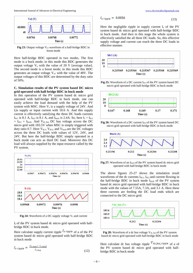
Fig 23: Output voltage Vo1 waveform of a half-bridge BDC in
boost mode
Here half-bridge BDC operated in two modes. The first
mode is a buck mode; in this mode this BDC generates the
output voltage Vo with the value of 20 V [average value].
The second mode is a boost mode; in this mode this BDC
generates an output voltage Vo1 with the value of 48V. The
output voltages of this BDC are determined by the duty ratio
of 50%.
C. Simulation results of the PV system based DC micro
grid operated with half-bridge BDC in buck mode
In this operation of the PV system based dc micro grid
operated with half-bridge BDC in buck mode, one can
easily achieve the load demand with the help of the PV
system with MSC. Here Vs is a supply voltage of 24V. And
Isis supply or input current with 18.6 A. And this supply
current is effectively satisfying the three DC loads currents
Idc1 is 8.1 A, Idc2 is 8.1 A, and Ibuck is 2.4A. So, here Is = Idc1
+ Idc2 + Ibuck. And Vdc_bus DC bus voltage across the DC
micro grid with 183.5V when MSC is simply triggered with
duty ratio 0.7. Here Vdc1, Vdc2, and Vbuck are the DC voltages
across the three DC loads with values of 12V, 24V, and
24V. But here the half-bridge BDC simply operated in a
buck mode can acts as third DC load. Moreover this DC
load will always supplied by the input resource called by the
PV system.
Fig 24: Waveform of a DC supply voltage Vs and current
Is of the PV system based dc micro grid operated with half-
bridge BDC in buck mode.
Here calculate supply current ripple of a of the PV
system based dc micro grid operated with half-bridge BDC
in buck mode
(12)
(13)
Here the negligible ripple in supply current Is of the PV
system based dc micro grid operated with half-bridge BDC
in buck mode. And then in this stage the whole system is
effectively satisfied the all three DC loads. So, this effective
supply voltage and current can reach the three DC loads in
effective manner.
Fig 25: Waveform of a DC current Idc1 of the PV system based DC
micro grid operated with half-bridge BDC in buck mode
Fig 26: Waveform of a DC current Idc2 of the PV system based DC
micro grid operated with half-bridge BDC in buck mode
Fig 27: Waveform of an Ibuck of the PV system based dc micro grid
operated with half-bridge BDC in buck mode
The above figures 25-27 shows the simulation result
waveforms of the dc currents Idc1, Idc2 and current flowing in
the half-bridge BDC in buck mode Ibuck of the PV system
based dc micro grid operated with half-bridge BDC in buck
mode with the values of 7.55A, 7.3A, and 3.1 A. Here these
three currents are feeding the DC load ends which are
connected to the DC micro grid.
Fig 28: Waveform of a dc bus voltage Vdc_bus of the PV system
based dc micro grid operated with half-bridge BDC in buck mode
Here calculate dc bus voltage ripple of a of
the PV system based dc micro grid operated with half-
bridge BDC in buck mode
International Journal of Advances in Electrical Engineering www.electricaltechjournal.com
~ 9 ~
(14)
(15)
Here the negligible voltage ripple in dc bus voltage Vdc_bus
of the PV system based dc micro grid operated with half-
bridge BDC in buck mode. And then in this stage the whole
system is effectively satisfied the all three DC loads. So, this
effective supply voltage and current can reach the three DC
loads in effective manner.
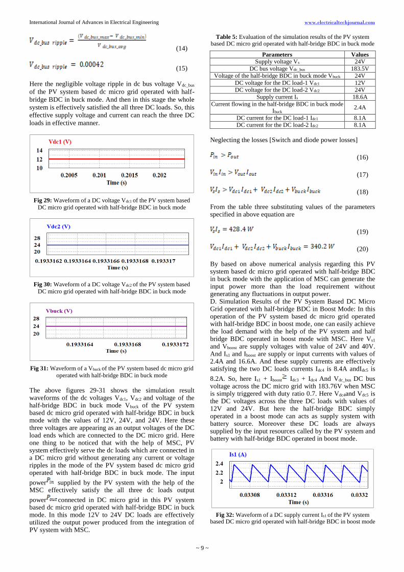
Fig 29: Waveform of a DC voltage Vdc1 of the PV system based
DC micro grid operated with half-bridge BDC in buck mode
Fig 30: Waveform of a DC voltage Vdc2 of the PV system based
DC micro grid operated with half-bridge BDC in buck mode
Fig 31: Waveform of a Vbuck of the PV system based dc micro grid
operated with half-bridge BDC in buck mode The above figures 29-31 shows the simulation result waveforms of the dc voltages Vdc1, Vdc2 and voltage of the half-bridge BDC in buck mode Vbuck of the PV system based dc micro grid operated with half-bridge BDC in buck mode with the values of 12V, 24V, and 24V. Here these three voltages are appearing as an output voltages of the DC load ends which are connected to the DC micro grid. Here one thing to be noticed that with the help of MSC, PV system effectively serve the dc loads which are connected in a DC micro grid without generating any current or voltage ripples in the mode of the PV system based dc micro grid operated with half-bridge BDC in buck mode. The input
power supplied by the PV system with the help of the MSC effectively satisfy the all three dc loads output
power connected in DC micro grid in this PV system based dc micro grid operated with half-bridge BDC in buck mode. In this mode 12V to 24V DC loads are effectively utilized the output power produced from the integration of PV system with MSC.
Table 5: Evaluation of the simulation results of the PV system based DC micro grid operated with half-bridge BDC in buck mode
Parameters Values
Supply voltage Vs 24V
DC bus voltage Vdc_bus 183.5V
Voltage of the half-bridge BDC in buck mode Vbuck 24V
DC voltage for the DC load-1 Vdc1 12V
DC voltage for the DC load-2 Vdc2 24V
Supply current Is 18.6A
Current flowing in the half-bridge BDC in buck mode Ibuck
2.4A
DC current for the DC load-1 Idc1 8.1A
DC current for the DC load-2 Idc2 8.1A
Neglecting the losses [Switch and diode power losses]
(16)
(17)
(18) From the table three substituting values of the parameters specified in above equation are
(19)
(20) By based on above numerical analysis regarding this PV system based dc micro grid operated with half-bridge BDC in buck mode with the application of MSC can generate the input power more than the load requirement without generating any fluctuations in output power. D. Simulation Results of the PV System Based DC Micro Grid operated with half-bridge BDC in Boost Mode: In this operation of the PV system based dc micro grid operated with half-bridge BDC in boost mode, one can easily achieve the load demand with the help of the PV system and half bridge BDC operated in boost mode with MSC. Here Vs1 and Vboost are supply voltages with value of 24V and 40V. And Is1 and Iboost are supply or input currents with values of 2.4A and 16.6A. And these supply currents are effectively satisfying the two DC loads currents Idc4 is 8.4A andIdc5 is
8.2A. So, here Is1 + Iboost Idc3 + Idc4 And Vdc_bus DC bus voltage across the DC micro grid with 183.76V when MSC is simply triggered with duty ratio 0.7. Here Vdc4and Vdc5 is the DC voltages across the three DC loads with values of 12V and 24V. But here the half-bridge BDC simply operated in a boost mode can acts as supply system with battery source. Moreover these DC loads are always supplied by the input resources called by the PV system and battery with half-bridge BDC operated in boost mode.
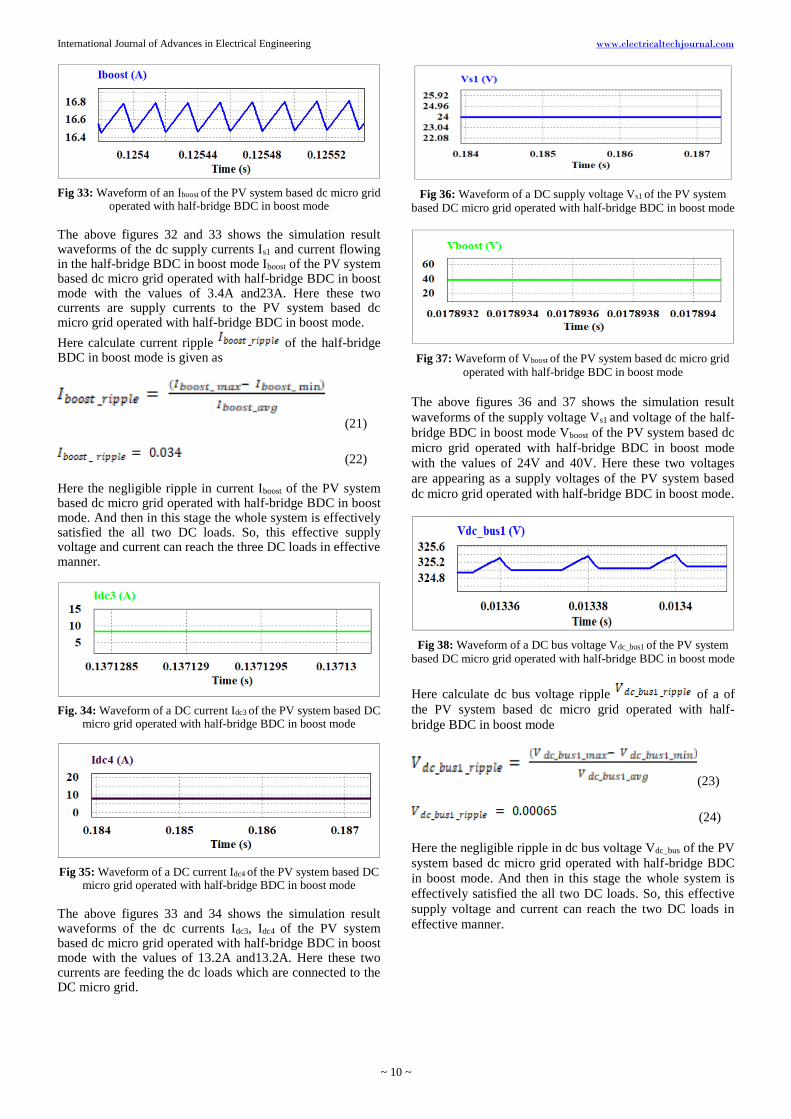
Fig 32: Waveform of a DC supply current Is1 of the PV system based DC micro grid operated with half-bridge BDC in boost mode
International Journal of Advances in Electrical Engineering www.electricaltechjournal.com
~ 10 ~
Fig 33: Waveform of an Iboost of the PV system based dc micro grid operated with half-bridge BDC in boost mode
The above figures 32 and 33 shows the simulation result waveforms of the dc supply currents Is1 and current flowing in the half-bridge BDC in boost mode Iboost of the PV system based dc micro grid operated with half-bridge BDC in boost mode with the values of 3.4A and23A. Here these two currents are supply currents to the PV system based dc micro grid operated with half-bridge BDC in boost mode.
Here calculate current ripple of the half-bridge BDC in boost mode is given as
(21)
(22) Here the negligible ripple in current Iboost of the PV system based dc micro grid operated with half-bridge BDC in boost mode. And then in this stage the whole system is effectively satisfied the all two DC loads. So, this effective supply voltage and current can reach the three DC loads in effective manner.
Fig. 34: Waveform of a DC current Idc3 of the PV system based DC micro grid operated with half-bridge BDC in boost mode
Fig 35: Waveform of a DC current Idc4 of the PV system based DC micro grid operated with half-bridge BDC in boost mode
The above figures 33 and 34 shows the simulation result waveforms of the dc currents Idc3, Idc4 of the PV system based dc micro grid operated with half-bridge BDC in boost mode with the values of 13.2A and13.2A. Here these two currents are feeding the dc loads which are connected to the DC micro grid.
Fig 36: Waveform of a DC supply voltage Vs1 of the PV system
based DC micro grid operated with half-bridge BDC in boost mode
Fig 37: Waveform of Vboost of the PV system based dc micro grid
operated with half-bridge BDC in boost mode
The above figures 36 and 37 shows the simulation result
waveforms of the supply voltage Vs1 and voltage of the half-
bridge BDC in boost mode Vboost of the PV system based dc
micro grid operated with half-bridge BDC in boost mode
with the values of 24V and 40V. Here these two voltages
are appearing as a supply voltages of the PV system based
dc micro grid operated with half-bridge BDC in boost mode.
Fig 38: Waveform of a DC bus voltage Vdc_bus1 of the PV system
based DC micro grid operated with half-bridge BDC in boost mode
Here calculate dc bus voltage ripple of a of
the PV system based dc micro grid operated with half-
bridge BDC in boost mode
(23)
(24)
Here the negligible ripple in dc bus voltage Vdc_bus of the PV
system based dc micro grid operated with half-bridge BDC
in boost mode. And then in this stage the whole system is
effectively satisfied the all two DC loads. So, this effective
supply voltage and current can reach the two DC loads in
effective manner.
International Journal of Advances in Electrical Engineering www.electricaltechjournal.com
~ 11 ~
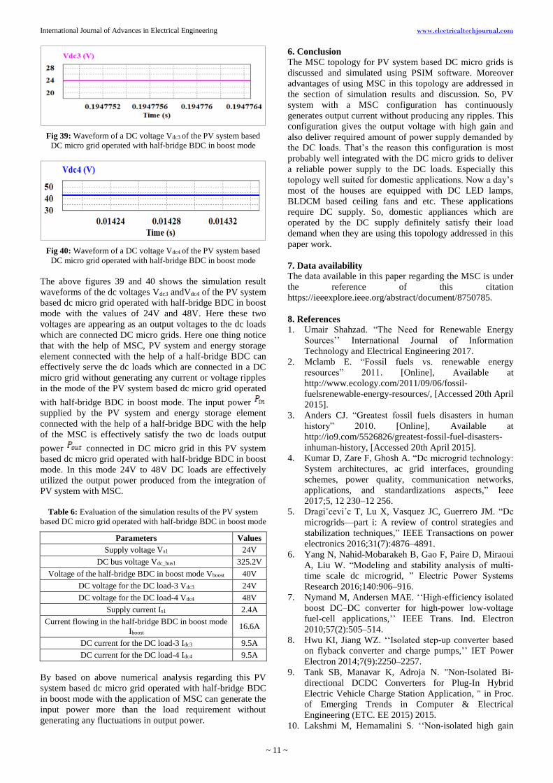
Fig 39: Waveform of a DC voltage Vdc3 of the PV system based
DC micro grid operated with half-bridge BDC in boost mode
Fig 40: Waveform of a DC voltage Vdc4 of the PV system based
DC micro grid operated with half-bridge BDC in boost mode
The above figures 39 and 40 shows the simulation result
waveforms of the dc voltages Vdc3 andVdc4 of the PV system
based dc micro grid operated with half-bridge BDC in boost
mode with the values of 24V and 48V. Here these two
voltages are appearing as an output voltages to the dc loads
which are connected DC micro grids. Here one thing notice
that with the help of MSC, PV system and energy storage
element connected with the help of a half-bridge BDC can
effectively serve the dc loads which are connected in a DC
micro grid without generating any current or voltage ripples
in the mode of the PV system based dc micro grid operated
with half-bridge BDC in boost mode. The input power
supplied by the PV system and energy storage element
connected with the help of a half-bridge BDC with the help
of the MSC is effectively satisfy the two dc loads output
power connected in DC micro grid in this PV system
based dc micro grid operated with half-bridge BDC in boost
mode. In this mode 24V to 48V DC loads are effectively
utilized the output power produced from the integration of
PV system with MSC.
Table 6: Evaluation of the simulation results of the PV system
based DC micro grid operated with half-bridge BDC in boost mode
Parameters Values
Supply voltage Vs1 24V
DC bus voltage Vdc_bus1 325.2V
Voltage of the half-bridge BDC in boost mode Vboost 40V
DC voltage for the DC load-3 Vdc3 24V
DC voltage for the DC load-4 Vdc4 48V
Supply current Is1 2.4A
Current flowing in the half-bridge BDC in boost mode
Iboost 16.6A
DC current for the DC load-3 Idc3 9.5A
DC current for the DC load-4 Idc4 9.5A
By based on above numerical analysis regarding this PV
system based dc micro grid operated with half-bridge BDC
in boost mode with the application of MSC can generate the
input power more than the load requirement without
generating any fluctuations in output power.
6. Conclusion
The MSC topology for PV system based DC micro grids is
discussed and simulated using PSIM software. Moreover
advantages of using MSC in this topology are addressed in
the section of simulation results and discussion. So, PV
system with a MSC configuration has continuously
generates output current without producing any ripples. This
configuration gives the output voltage with high gain and
also deliver required amount of power supply demanded by
the DC loads. That’s the reason this configuration is most
probably well integrated with the DC micro grids to deliver
a reliable power supply to the DC loads. Especially this
topology well suited for domestic applications. Now a day’s
most of the houses are equipped with DC LED lamps,
BLDCM based ceiling fans and etc. These applications
require DC supply. So, domestic appliances which are
operated by the DC supply definitely satisfy their load
demand when they are using this topology addressed in this
paper work.
7. Data availability
The data available in this paper regarding the MSC is under
the reference of this citation
https://ieeexplore.ieee.org/abstract/document/8750785.
8. References
1. Umair Shahzad. “The Need for Renewable Energy
Sources’’ International Journal of Information
Technology and Electrical Engineering 2017.
2. Mclamb E. “Fossil fuels vs. renewable energy
resources” 2011. [Online], Available at
http://www.ecology.com/2011/09/06/fossil-
fuelsrenewable-energy-resources/, [Accessed 20th April
2015].
3. Anders CJ. “Greatest fossil fuels disasters in human
history” 2010. [Online], Available at
http://io9.com/5526826/greatest-fossil-fuel-disasters-
inhuman-history, [Accessed 20th April 2015].
4. Kumar D, Zare F, Ghosh A. “Dc microgrid technology:
System architectures, ac grid interfaces, grounding
schemes, power quality, communication networks,
applications, and standardizations aspects,” Ieee
2017;5, 12 230–12 256.
5. Dragiˇcevi´c T, Lu X, Vasquez JC, Guerrero JM. “Dc
microgrids—part i: A review of control strategies and
stabilization techniques,” IEEE Transactions on power
electronics 2016;31(7):4876–4891.
6. Yang N, Nahid-Mobarakeh B, Gao F, Paire D, Miraoui
A, Liu W. “Modeling and stability analysis of multi-
time scale dc microgrid, ” Electric Power Systems
Research 2016;140:906–916.
7. Nymand M, Andersen MAE. ‘‘High-efficiency isolated
boost DC–DC converter for high-power low-voltage
fuel-cell applications,’’ IEEE Trans. Ind. Electron
2010;57(2):505–514.
8. Hwu KI, Jiang WZ. ‘‘Isolated step-up converter based
on flyback converter and charge pumps,’’ IET Power
Electron 2014;7(9):2250–2257.
9. Tank SB, Manavar K, Adroja N. "Non-Isolated Bi-
directional DCDC Converters for Plug-In Hybrid
Electric Vehicle Charge Station Application, " in Proc.
of Emerging Trends in Computer & Electrical
Engineering (ETC. EE 2015) 2015.
10. Lakshmi M, Hemamalini S. ‘‘Non-isolated high gain
International Journal of Advances in Electrical Engineering www.electricaltechjournal.com
~ 12 ~
DC–DC converter for DC microgrids, ’’ IEEE Trans.
Ind. Electron 2018;65(2):1205–1212.
11. Li W, He X. ‘‘Review of non-isolated high-step-up
DC/DC converters in photovoltaic grid-connected
applications,’’ IEEE Trans. Ind. Electron
2011;58(4):1239–1250.
12. Cao Y, Samavatian V, Kaskani K, Eshraghi H. A novel
non-isolated ultra-high-voltage-gain DC–DC converter
with low voltage stress,’’ IEEE Trans. Ind. Electron
2017;64(4):2809–2819.
13. Yu D, Yang J, Xu R, Xia Z, C Iu HH, Fernando T. ‘‘A
family of module-integrated high step-up converters
with dual coupled inductors,’’ IEEE Access
2018;6:16256–16266.
14. Zhang M, Xing Y, Wu H, Hu H, Ma X. ‘‘A dual
coupled inductors based high step-up/step-down
bidirectional DC-DC converter for energy storage
system,’’ in Proc. IEEE Appl. Power Electron. Conf.
Expo. (APEC), Tampa, FL, USA 2017, 2958–2963.
15. Nilanjan M, Dani S. ‘‘Control of cascaded DC–DC
converter-based hybrid battery energy storage
systems—Part I: Stability issue, ’’ IEEE Trans. Ind.
Electron 2016;63(4):2340–2349.
16. Rosas-Caro JC, Mancilla-David F, Mayo-Maldonado
JC, Gonzalez-Lopez JM, Torres-Espinosa HL, Valdez-
Resendiz JE, ‘‘A transformer-less high-gain boost
converter with input current ripple cancelation at a
selectable duty cycle, ’’ IEEE Trans. Ind. Electron
2013;60(10):4492–4499.
17. Yu Tang, Member IEEE, Ting Wang, Yaohua A.
Switched-Capacitor-Based Active-Network Converter
With High Voltage Gain H IEEE Transactions On
Power Electronics 2014;29(6):2959.
18. Wu B, Li S, Liu Y, Smedley KM. ‘‘A new hybrid
boosting converter for renewable energy applications,’’
IEEE Trans. Power Electron 2016;31(2):1203–1215.
19. Rosas-Caro JC, Mancilla-David F, Mayo-Maldonado
JC, Gonzalez-Lopez JM, Torres-Espinosa HL, Valdez-
Resendiz JE. ‘‘A transformer-less high-gain boost
converter with input current ripple cancelation at a
selectable duty cycle, ’’ IEEE Trans. Ind. Electron
2013;60(10):4492–4499.
20. Beena1 KH, Anish Benny. 2 PG Student, Dept. of EEE,
AmalJyothi College of Engineering, Kottayam, Kerala
India1 Assistant Professor, Dept. of EEE, AmalJyothi
College of Engineering, Kottayam, Kerala
IndiaAnalysis and Implementation of Quadratic Boost
Converter for Nanogrid Applications 2015;4(7).
Copyright to IJAREEIE DOI:
10.15662/ijareeie.2015.0407030 6043.
21. Pandav Kiran Maroti, (Member, IEEE), Sanjeevi
Kumar Padmanaban, (Senior Member, IEEE), Jens Bo
Holm-Nielsen, Mahajan Sagar Bhaskar, (Member,
IEEE), Mohammad Meraj, (Student Member, IEEE),
Atif Iqbal, (Senior Member, IEEE). “A New Structure
of High Voltage Gain SEPIC Converter for Renewable
Energy Applications” 2019. Digital Object Identifier
10.1109/ACCESS.2019.
22. Wuhua Li, Member IEEE, Xiangning He. Fellow
Review of Non-isolated High-Step-Up DC/DC
Converters in Photovoltaic Grid-Connected
Applications, IEEE IEEE Transactions on Industrial
Electronics 2011;58(4):1239.
23. “Comparison of Photovoltaic Array Maximum Power
Point Tracking Techniques”, Trishan Esram, Student
Member Patrick L. Chapman, Member. National
Science Foundation ECS-01-34208 2011.
24. “Maximum Power Point Tracker for Photovoltaic
Systems with Resistive Load”. G. De Cesar, D. Captuo
and A. Nascetti, Solar Energy 2006;80:982-988.
25. Caricchi F, Crescimbini F, Noia G, Pirolo D.
"Experimental study of a bidirectional DC-DC
converter for the DC link voltage control and the
regenerative braking in PM motor drives devoted to
electrical vehicles," in Proc. of 9th Annual Applied
Power Electronics Conference and Exposition (APEC
1994), Orlando 1994.
26. Denny DC, Shahin M. "Analysis of bidirectional
SEPIC/Zeta converter with coupled inductor, "In Proc.
of International Conference on Advancements in Power
and Energy (TAP Energy 2015), Kollam 2015.