Embed Size (px)
Citation preview

P. JansweijerNikhefAmsterdamElectronics- Technology
October 15, 2009 1 VLVnT-09 Athens
Measuring propagation Measuring propagation delay over a coded serial delay over a coded serial communication channel communication channel
using FPGAsusing FPGAs
P.P.M. Jansweijer, H.Z. PeekP.P.M. Jansweijer, H.Z. Peek
P. JansweijerNikhefAmsterdamElectronics- Technology
October 15, 2009 2 VLVnT-09 Athens
IntroductionIt is feasible to measure propagation
delay over an 8B/10B coded link over 100 Km of fibre
A 3.125 Gbps serial link implemented in FPGA provides a resolution of 320 ps.
The method presented originates from thinking about KM3NeT timing…
…but applies more general to “Measurement and control applications”
P. JansweijerNikhefAmsterdamElectronics- Technology
October 15, 2009 3 VLVnT-09 Athens
OM
OM
OM
OM
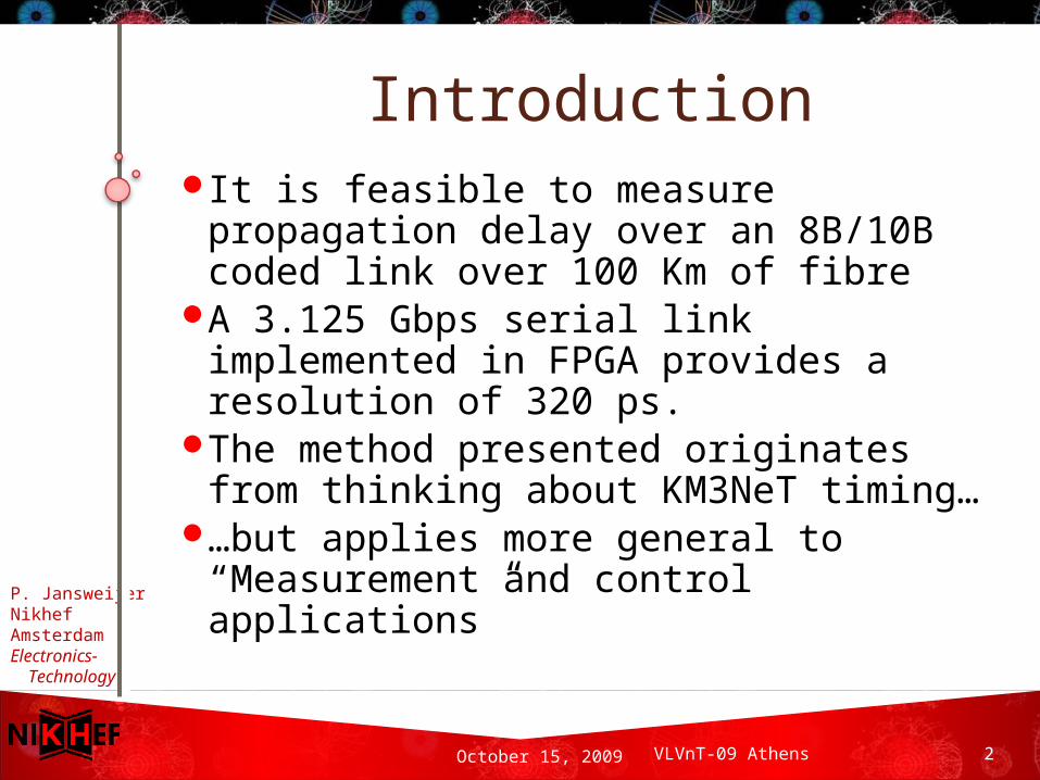
Measurement and control application example - I
KM3NeT
ShoreStation
GPS
OM
1 Km
1 K
m
1 Km
OM
OM
OM
Distributed: 1 cubic Kilometer
Synchronize system timing
High precision: ~ 1 ns
P. JansweijerNikhefAmsterdamElectronics- Technology
October 15, 2009 4 VLVnT-09 Athens
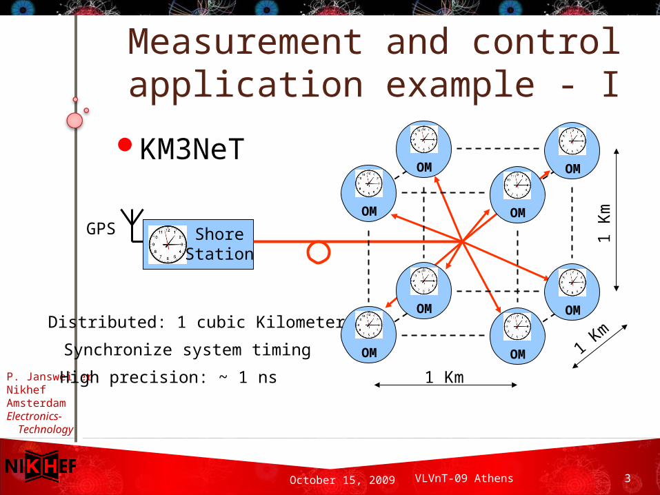
Measurement and control application example - II
(Super) LHCP4
P5
P8
P2 CCR
TTC backbone
TTC off-detector
TTC on-detector
From a presentation given at theATLAS Upgrade "ROD" Workshop Sophie Baron – CERNJune 18, 2009
Synchronize system timingHigh precision: aim < 100 ps
Distributed: LHC diameter 8,6 Km
P. JansweijerNikhefAmsterdamElectronics- Technology
October 15, 2009 5 VLVnT-09 Athens
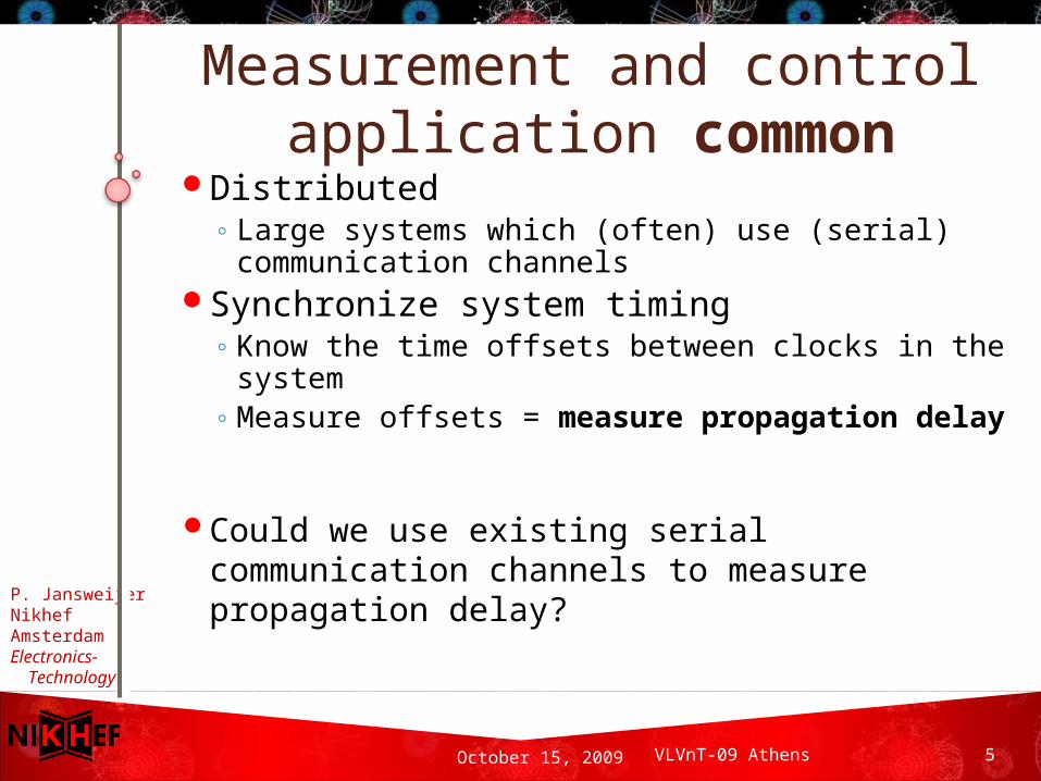
Measurement and control application common
Distributed◦ Large systems which (often) use (serial)
communication channelsSynchronize system timing
◦ Know the time offsets between clocks in the system
◦ Measure offsets = measure propagation delay
Could we use existing serial communication channels to measure propagation delay?
P. JansweijerNikhefAmsterdamElectronics- Technology
October 15, 2009 6 VLVnT-09 Athens
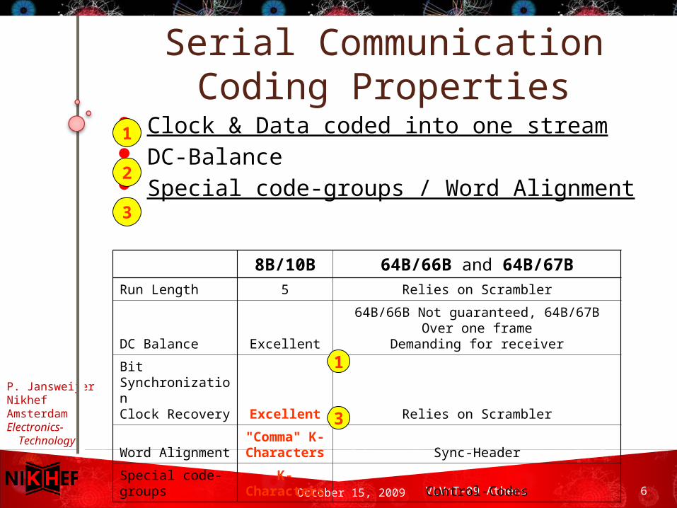
Serial Communication Coding Properties
Clock & Data coded into one stream DC-Balance Special code-groups / Word Alignment
8B/10B 64B/66B and 64B/67BRun Length 5 Relies on Scrambler
DC Balance Excellent
64B/66B Not guaranteed, 64B/67B Over one frame
Demanding for receiver
Bit SynchronizationClock Recovery Excellent Relies on Scrambler
Word Alignment
"Comma" K-
Characters Sync-Header
Special code-groups
K-Characters Control-Codes
1
2
3
1
3
P. JansweijerNikhefAmsterdamElectronics- Technology
October 15, 2009 7 VLVnT-09 Athens
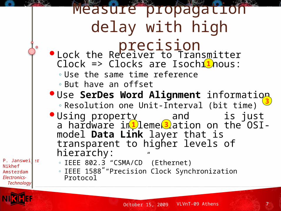
Measure propagation delay with high precision
Lock the Receiver to Transmitter Clock => Clocks are Isochronous:◦ Use the same time reference◦ But have an offset
Use SerDes Word Alignment information◦ Resolution one Unit-Interval (bit time)
Using property and is just a hardware implementation on the OSI-model Data Link layer that is transparent to higher levels of hierarchy:◦ IEEE 802.3 “CSMA/CD” (Ethernet)◦ IEEE 1588 “Precision Clock Synchronization Protocol”
1
31
3
P. JansweijerNikhefAmsterdamElectronics- Technology
October 15, 2009 8 VLVnT-09 Athens
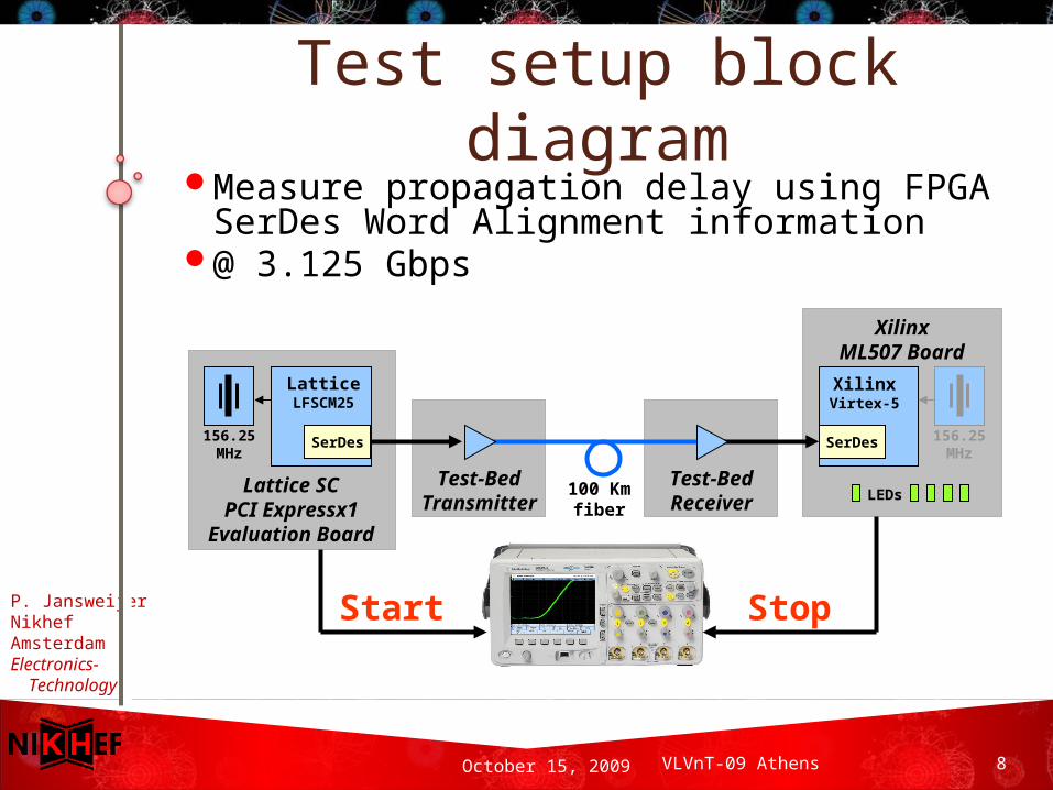
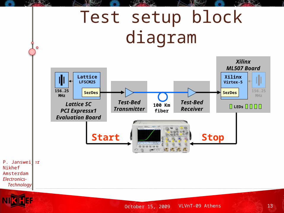
Test setup block diagram
Start
Test-BedTransmitter
LatticeLFSCM25
SerDes
Lattice SCPCI Expressx1
Evaluation Board
XilinxVirtex-5
SerDes
XilinxML507 Board
LEDs
Stop
100 Kmfiber
156.25MHz
156.25MHz
Test-BedReceiver
Measure propagation delay using FPGA SerDes Word Alignment information
@ 3.125 Gbps
P. JansweijerNikhefAmsterdamElectronics- Technology
October 15, 2009 9 VLVnT-09 Athens
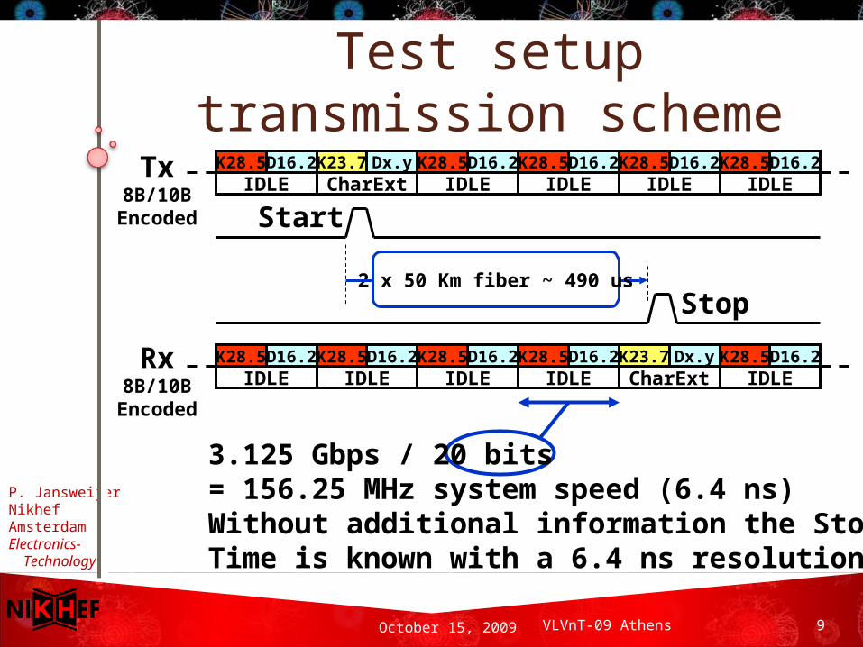
Test setup transmission scheme
Tx8B/10B
Encoded Start
2 x 50 Km fiber ~ 490 us
3.125 Gbps / 20 bits= 156.25 MHz system speed (6.4 ns)Without additional information the StopTime is known with a 6.4 ns resolution
K28.5 D16.2IDLE
K28.5 D16.2IDLE
K28.5 D16.2IDLE
K28.5 D16.2IDLE
K23.7 Dx.yCharExt
K28.5 D16.2IDLE
K28.5 D16.2IDLE
K28.5 D16.2IDLE
K28.5 D16.2IDLE
K28.5 D16.2IDLE
K23.7 Dx.yCharExt
K28.5 D16.2IDLE
Rx8B/10B
Encoded
Stop
P. JansweijerNikhefAmsterdamElectronics- Technology
October 15, 2009 10 VLVnT-09 Athens
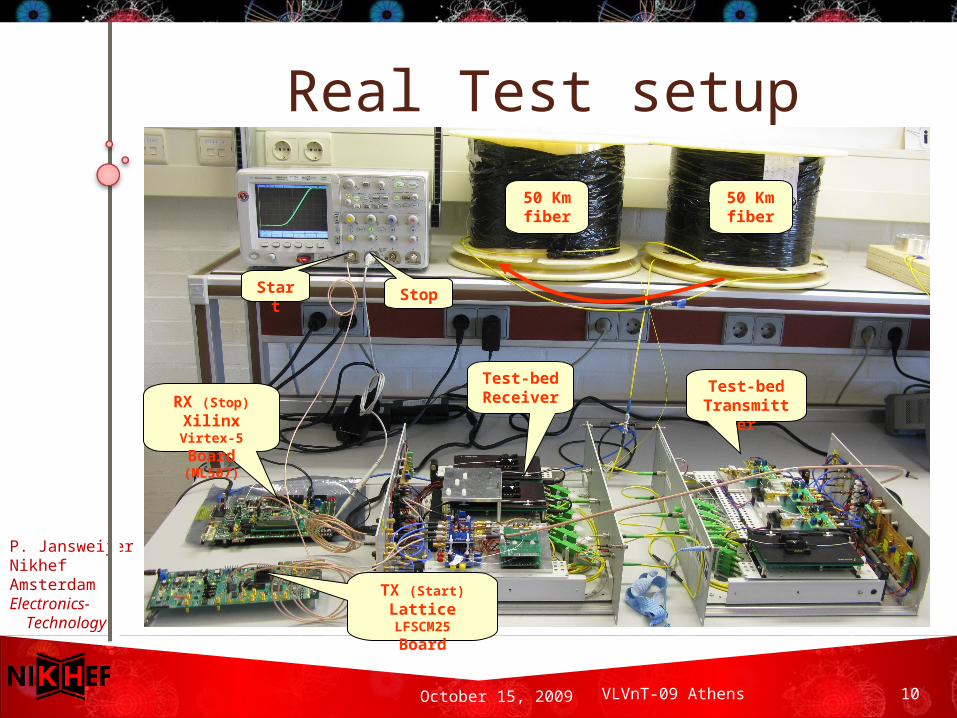
RX (Stop)
Xilinx Virtex-5
Board (ML507)
TX (Start)
Lattice LFSCM25
Board
Start Stop
50 Kmfiber
50 Kmfiber
Test-bedReceiver
Test-bedTransmitter
Real Test setup
P. JansweijerNikhefAmsterdamElectronics- Technology
October 15, 2009 11 VLVnT-09 Athens
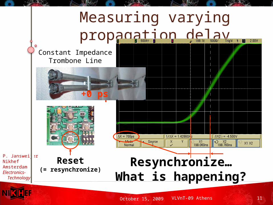
Measuring varying propagation delay
Constant ImpedanceTrombone Line
+700 ps+0 ps
Reset(= resynchronize)
Resynchronize…What is happening?
P. JansweijerNikhefAmsterdamElectronics- Technology
October 15, 2009 12 VLVnT-09 Athens
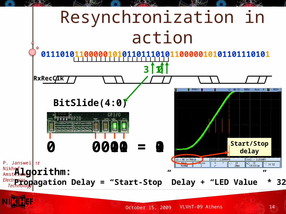
What happens during resynchronization
1. TX is transmitting a serial bit stream based on the reference clock
2. RX using the reference clock to try to lock its PLL in the CDR onto the incoming bit stream (note: usually the TX and RX reference clock do not have the same source...)
3. Once the PLL in the CDR is in phase, RX switches over from its reference clock to the RX recovered clock “RxRecClk” (this happens on a random bit)
4. Next the Word Aligner is searching for a “Comma”
5. Once a Comma is found the word aligner knows how to set its multiplexer and feed properly aligned sets of 20 bits to the FPGA fabric
P. JansweijerNikhefAmsterdamElectronics- Technology
October 15, 2009 13 VLVnT-09 Athens
Test setup block diagram
Start
Test-BedTransmitter
LatticeLFSCM25
SerDes
Lattice SCPCI Expressx1
Evaluation Board
XilinxVirtex-5
SerDes
XilinxML507 Board
LEDs
Stop
100 Kmfiber
156.25MHz
156.25MHz
Test-BedReceiver
P. JansweijerNikhefAmsterdamElectronics- Technology
October 15, 2009 14 VLVnT-09 Athens
0 0001 = 1 0 0000 = 0 0 0011 = 3
Resynchronization in action
RxRecClk
BitSlide(4:0)
011101011000001010110111010110000010101101110101
0
Algorithm:Propagation Delay = “Start-Stop” Delay + “LED Value” * 320 ps
Start/Stopdelay
3 1
P. JansweijerNikhefAmsterdamElectronics- Technology
October 15, 2009 15 VLVnT-09 Athens
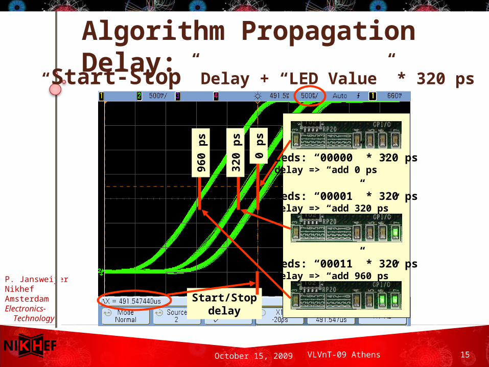
Start/Stopdelay
Leds: “00000” * 320 psdelay => “add 0 ps”32
0 p
s
960
ps
0 p
s
Leds: “00001” * 320 psdelay => “add 320 ps”
Leds: “00011” * 320 psdelay => “add 960 ps”
Algorithm Propagation Delay:“Start-Stop” Delay + “LED Value” * 320 ps
P. JansweijerNikhefAmsterdamElectronics- Technology
October 15, 2009 16 VLVnT-09 Athens
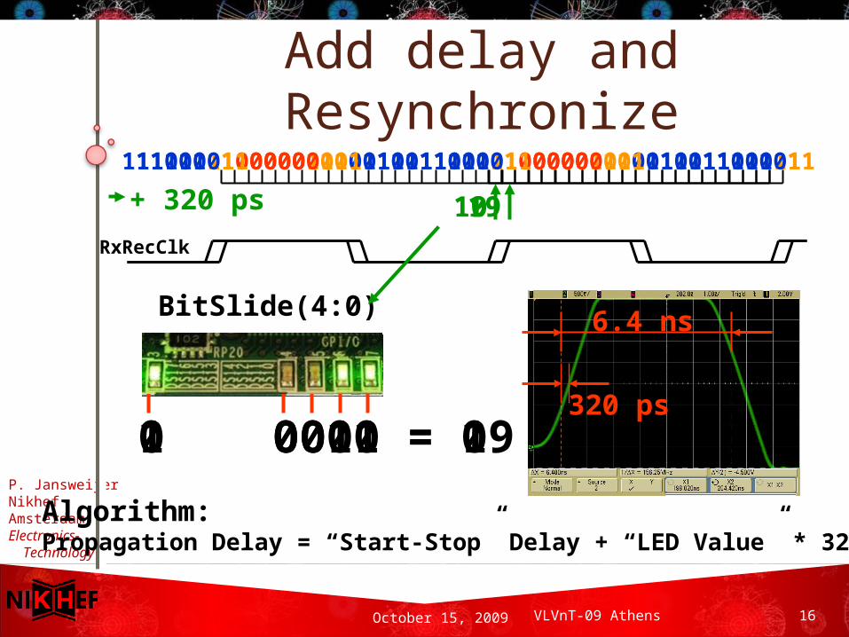
Add delay and Resynchronize
RxRecClk
BitSlide(4:0)
111010110000010101101110101100000101011011101011
Algorithm:Propagation Delay = “Start-Stop” Delay + “LED Value” * 320 ps
190
6.4 ns
1 0011 = 19 0 0000 = 0
+ 320 ps
111010110000010101101110101100000101011011101011
19
320 ps
P. JansweijerNikhefAmsterdamElectronics- Technology
October 15, 2009 17 VLVnT-09 Athens
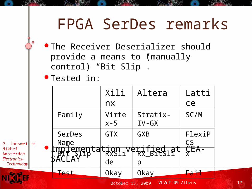
FPGA SerDes remarksThe Receiver Deserializer should
provide a means to (manually control) “Bit Slip”.
Tested in:
Implementation verified at CEA-SACLAY
Xilinx Altera Lattice
Family Virtex-5
Stratix-IV-GX
SC/M
SerDes Name
GTX GXB FlexiPCS
Bit Slip RxSlide
Rx_BitSlip x
Test Okay Okay Fail
P. JansweijerNikhefAmsterdamElectronics- Technology
October 15, 2009 18 VLVnT-09 Athens
ConclusionIt is feasible to measure
propagation delay over an 8B/10B coded link over 100 Km of fibre.
A 3.125 Gbps serial link provides a resolution of 320 ps.
This can be implemented in an FPGA Thank you