Embed Size (px)
Citation preview


P. O. Box 7500, Charlotte, North Carolina 28241 / Telephone: (704) 588-3030 / Fax: (704) 588-3039 / e-mail: [email protected] / www.csiheat.com
To: CSI Customers and Friends
We appreciate your taking the time to review this brochure. It contains timely guidelines on the
design and construction of jacketed piping systems, as well as plenty of details and examples.
From my perspective of more than 20 years in the jacketed piping business, the most significant
information we’re leaving with you are facts that pinpoint the critical nature of a jacketed piping
system, and why you need to select a qualified fabricator to avoid problems too common in the
majority of jacketed piping projects.
I’m talking about problems of heat transfer, of core/jacket stresses, and of cross contamination.
It’s important for process and project engineers to appreciate the effects and consequences of
poor piping design, non-code fabrication, installation mismatches, and poor layout. As an old
Shift Supervisor, I know that an emergency call at 2:00 in the morning because the plant’s pro-
ducing off-grade product with traces of hot oil probably isn’t operator error. Most likely, it’s
fabricator error.
From experience, let me tell you that when you involve the jacketed piping specialist early in
your project—even during preliminary discussions—your chances of on-time, on-budget success
increase substantially.
In many instances, our customers are unaware of CSI’s extensive capabilities. Again and again,
I’ve listened to customers say, "We didn’t know you guys did that!" Usually, it’s in reference to
one of our un-promoted services such as on-site layout, or a thermal analysis of jacket "A"
design vs. jacket "B" design.
The fact is, we developed these special capabilities because we want to take care of our
customers. CSI can assume full responsibility for your jacketed piping project—part of it,
or all of it—from concept to installation.
May we serve your company?
Thanks,
Fred H. Stubblefield, Jr.
President
1

The risk of cross contamination must beavoided for the projected life of the piping system.Cross contamination occurs most frequently at the heat affected zones of weldments. To avoid cross contami-nation, some designers opt to exclude concealed weldsbeneath the jacket, choosing swaged jacketing on straightsections and leaving fittings un-jacketed. Where narrowthermal profiles must be maintained, bolt-on heatingjackets can provide heat coverage for the fittings andflanges (see Hybrid Jacketing, page 9). Regardless ofthe fabrication techniques specified, the designer’s bestdefense against cross contamination is thorough engineer-ing, knowledgeable inspection, and expert fabrication.
Batch-type processes that cycle to 250˚For higher create stress problems that mustbe resolved before fabrication.Frequent thermal cycling of jacketed piping used in batch-type service induces cyclic stresses in the core andjacket. Forced-fit installations of the jacketed pipe coupledwith cyclic heat loads lead to premature cracking of flangewelds--the welds usually most susceptible to thermalcycling. The higher the processing temperature, themore important it is to treat batch-process pipingas critical equipment. When different material forthe core and jacket are specified, such as a car-bon jacket and a stainless core, stress in the coremay exceed ASME Code recommendations. Stressanalysis of the piping system, as well as design configura-tions of core and jacket, should be performed.
2
Choo
se A
Spe
cial
ist:
CSI
Jacketed piping, unlike single-wall(unjacketed) piping, is special.Navigating successfully through jacketed piping’s maze of potentialproblems requires a specialist’s skilland knowledge.
The potential problems startwith the fundamental differencesbetween the fabricating techniquesof jacketed piping and those of single-wall piping. With single-wallpiping, a fabricator begins at oneflanged end, then adds piping com-ponents in sequence. With jacketedpiping, the fabricator starts in themiddle of the spool, adding tees,elbows and other segments, workingoutward to the flanges. Thissequence is necessary to avoidexcessive jacket welds and “clam-shell” construction.
It’s important that design teamsremember this fundamental difference.Often, to maintain project milestones,
the design team assigns the fabrica-tion of their jacketed piping to a general pipe shop or mechanicalcontractor along with the single-walland utility piping.
By delegating the fabrication ofthe jacketed piping to the contractor,the team achieves man-hour savingsby eliminating design and adminis-trative time required to isolate andseparate the jacketed piping from thetotal piping package. Since jacketedpiping usually represents only a smallsegment to the total piping work,there seems to be little justification forthe extra time and effort needed forthe breakout.
Unfortunately, when the con-tractor’s fabricators have minimalexperience with jacketed piping, orthe contractor’s most recent jacketedpiping work occurred several yearsago, the results often are the tandemproblems of poor quality and poor
performance.Other jacketed piping issues
that contractors seldom areequipped to resolve expediently arecode conflicts with design criteria,thermal stresses, heating mediumcircuitry, rigorous testing procedures,and complete documentation.
For the jacketed piping spe-cialist these problems occur daily.They are solved daily. All welding,fabrication, testing, QC inspection,design and engineering converge on the production of a basic type ofcritical equipment. Fabricators withquestions have ready access to expe-rienced designers and engineers.
Here are some of the typicalconditions of design, fabrication, andperformance that establish the criticalnature of jacketed piping. These con-ditions underscore the importance ofselecting the specialist to fabricateyour jacketed piping.
Choose A Specialist To Fabricate Your Jacketed Piping
Swaged jacketed pipe spool with stainless core and carbon jacket. The jacket has an integral stainless expan-sion joint to relieve cyclic heat stress.
Heat affected zones adjacent to welds are “weak links” injacketed piping systems. That’s where stress fractures occur most frequently. The result is cross contamination, shown above in a sulfur transfer line.Sulfur breached the jacket annulus.

3
High jacket pressures can collapse core piping.High core pressures dictate rigorous testing.Core piping should always be checked for external pressure loads created by the heating medium. If the core temperature rises higherthan the temperature of the heating medium, pressure consequencesfor the core may be too severe.
When the core piping operates above 1000 psi, heavy-wallpiping with 1500 lb. and 2500 lb. class flanges, or high-pressurehubs are required. Precision fabrication of heavy-wall jacketed pipingis critical for optimum installation. Rigorous nondestructive testingof core welds must be performed via radiographic (RT) or ultrasonictesting (UT) whenever practical. Fillet welds can be inspected byliquid penetrant testing (PT) or UT.
Thermal gradients, caused by inaccurate fabrication, affect product quality.When quality of the product can be affected by variations in process temperatures over the length of a pipe, standard dimen-sional checks (verifying face to face dimensions, etc.) are notenough. Thermal gradients occur when the core pipe comes incontact with the jacket or is so close to the jacket that the flow ofthe heating fluid is blocked. This stagnation area creates a chillspot that can cause variations in color or luster of some polymersand pigments. Serious stress problems may result. Fabricating aspool of jacketed pipe in two or three planes without the core pipetouching the jacket is a difficult task. Expert fabrication is required.When thermal gradients must be avoided, using a jacket size largerthan “standard” improves chances of success.
Maintaining close tolerances between numerous fixed points often calls for specialfabrication jigs and test fixtures.When jacketed pipe connects to precision machinery, the tolerances of matching nozzles is critical to the proper functioningof the entire system. Even with the help of jigs and optical alignmentdevices, maintaining the fabrication requirements of ASME B31.3can be very difficult. Crucial to success is a thorough understandingof the relationships between pipe schedules, cut lengths and weldshrinkage. Awkward configurations often prevent post machiningfrom correcting misalignments. Correct cut lengths, precise fit-ups,and excellent welding are the most effective tools to use in prevent-ing tolerance-related misalignment.
When the process is a hot, toxic fluid containedin a metallic jacket, stresses tend to be verysevere, requiring special designs.When the process chemicals are toxic, the quality of fabrication and welding is as important as inspection and testing. A number ofdifferent tests are needed to verify product integrity. These testsinclude RT, PT, UT, and positive material identification (PMI). Whenthe jacket purpose is containment and temperature control, designand construction of the piping calls for the extensive knowledge ofthe best welders and fitters. It also calls for the most experiencedengineers and inspectors available.
A sudden rise in process temperature caused thepressure of the steam in the jacket to increase dramatically, crushing the core.
Radiography reveals a core elbow blocking theheating medium, which can create a chill spot in the process and induce severe stresses in the core pipe.
To ensure precise alignment of mating equipment,piping jigs may be required.
Buried containment piping for hot processes createsspecial stress problems due to wide temperature differences between the core and jacket.
4
The surface finish of the core piping may needto be substantially better than mill grade.The quality of many polymers and foodstuffs depend on residence time in the hot process piping. Mill finishes and weldedjoints have voids and crevices where molten products stagnate,degrade, then break away, creating end products of poor quality.
Polished pipe surfaces help control residence time and eliminate product traps. Some processes require surface finishesapproaching that of a mirror. Butt welds that are accessible duringfabrication can be mechanically polished. Inaccessible butt weldsmust be carefully executed to ensure zero concavity of the surfaceand minimal protrusion of the weld into the product stream.Smoothness inspection methods include radiography and boroscopic examinations.
Mechanically polishing of butt welds is often neededfor heat sensitive products. Where polishing is notpossible, expert welding is required.
Radiographic and visual inspection of welds on titanium often fail to detect evidence of oxidation.Oxidized welds on titanium piping will disintegratewith the light tap of a hammer.
Test probe housings that penetrate the jacket intothe core are subject to welding deformation.Machining of the probe bore should be performedafter the probe housing is installed in the piping.
Test probes through the jacket into the corepiping have narrow dimensional tolerances.The stresses they create can be significant.Jacketed spools are often equipped with temperature andpressure probes inserted through the jacket into the core.Premachined probe housings often warp due to welding heat.Solution: Prepare an un-bored probe housing and adjacent pipingas a subassembly, then machine the instrument hole and sealingsurface in the housing after all welding around the housing is com-plete. Lastly, weld the subassembly into the spool, avoiding anywelding heat on the machined housing.
Mistakes with difficult-to-weld high alloys,such as AL6XN*, duplex stainless, Inconel*,Hastelloy*, or titanium are very expensive.Corrosive, high-temperature process fluids may require special, high-alloy piping. These high-alloy piping materialsdemand the skills of experienced welders and fabricators workingin controlled environments. Since all high-alloy materials areexpensive, inspection and testing by the supplier as well as thecustomer must be thorough.
*Trademark

5
Your
Adv
anta
ges
With
CSIWhat Are Your Advantages When You Select CSI?
Good PeopleGood people make good pipe. Many welders and fabricators atCSI have more than 10 years of service. Their safety record is abeacon in the industry.
The experienced welders and fabricators who producejacketed piping spools in CSI shops also install those spools inour customers’ plants. This system simplifies responsibility, pro-motes accountability, and maintains excellent team spirit.
FacilitiesCSI facilities hold the following authorizations from the ASMENational Board of Pressure Vessel Inspectors: “VR”, “PP”, “U” and “R”.
The foremost engineering concerns have surveyed thesefacilities, commenting on the quality of welding and expert fabricat-ing skills observed. We urge all of our customers to visit our facilities.
Know-HowMany customers depend on CSI’s experience to design and fabri-cate jacketed piping. Some look to us for help in solving specialheat transfer problems. Others count on our ability to assume fullresponsibility for their jacketed piping systems, starting with layoutsketches through installation and start-up.
On any given day, piping projects progressing through ourshops may be scheduled for sulfur service, polyester resin, sugar,Category M fluids, and several other processes.
This diversity of experience and know-how has a compellingbenefit: We have the confidence, ability, and willingness to helpyou solve difficult process heating problems.
Classroom and on-the-job trainingis the foundation of continuous
improvement at CSI.
A recent expansion: A special facility for high precision fabrication such as polymer manifolds and piping.
Visitors in the CSI shops usually see a variety of jacketed pipe under construction.
This CSI name tag on a spool of jacketed pipeis your assurance that it was produced by themost experienced team of fabricators in thebusiness.

6
QualityRadiographic examinations of CSI welders confirm acceptancerates above 99% for every inch of welding produced. This is aunique welding standard in the fabrication industry.
Many CSI craftsmen received comprehensive training in company-sponsored classes on welding, fabricating, math, blue-printreading, testing and safety. Our minimum quality standards are estab-lished by the ASME. We consistently exceed minimum standards.
CSI uses a variety of testing and inspection methods to verifyquality: Radiography, magnetic particle testing, ultrasonic testing,dye penetrant testing, mass spectrometer testing, boroscopicexamination, and visual examination.
ResponsibilityCSI stands ready to assume full responsibility for your jacketed piping system – all of it or parts of it. If you want us to assumeresponsibility for heating your entire system, including all compo-nents, we will. We’re prepared to accept responsibility for pipinglayouts, piping design, fit-ups and installations. We’ll assumeresponsibility for the thermal performance of the overall system,including process heat-up. We’ll assume responsibility for stressanalysis. We’ll assume responsibility for pressure drop analysis of the heating medium. From system layout to system sign-off, we make the assignment of responsibility easy, because whateverwe make, we’ll stand by it. And we’ll stand by you.
CommitmentIf our goal is to be the best at what we do, then our path is clear.Our customers must be satisfied with our products, our services,and our people. It is very important to us that our customers enjoydoing business with CSI. Our commitment: To take care of our customers to the very best of our abilities.
When you visit our facilities, we think you’ll see this commit-ment in action throughout the organization. You’ll see it reflected inthe years of service, knowledge, and experience that our productionpeople have achieved…in the level and diverse range of technicalexpertise offered by our engineering group…and in the productand process knowledge that our sales and customer service people willingly share with you.
Testing and inspection are important tools used byCSI to assure quality fabrication; however, thewelder’s craftsmanship and execution is the primaryingredient for premium quality.
CSI has assumed responsibilities for projects in theU.S and overseas. From system layout to systemsign-off, we are prepared to meet your challenges.
CSI has satisfied customers in every major chemical processing area of the U.S. We take special pride in taking care of our customers.

7
Types And Sizes Of Jacketed PipeThere are many different size combinations of jacketed pipe.Some of the more common types are charted in this section.Materials of construction vary widely, depending on theprocess, its temperature and pressure.
When the heating fluid is a vapor, the typical pipe sizecombinations are those shown in the left column. When theheating medium is a liquid, the typical size combinations arethose shown in the right column.
When different materials are used for the core pipeand the jacket pipe, the coefficients of expansion of thematerials should be similar, or the process should have a relatively low operating temperature. All jacketed piping sys-tems should be stress analyzed. All jacketed piping systemsshould be designed, constructed and tested in accordancewith a recognized industry code, such as ASME B31.3.
Jacketed Pipe SizesVapor Heating Media
(Core) x (Jacket)1" x 2"
1-1/2" x 2-1/2"2" x 3"3" x 4"4" x 6"6" x 8"8" x 10"10" x 12"12" x 14"
Jacketed Pipe SizesLiquid Heating Media
(Core) x (Jacket)1" x 2-1/2"
1" x 3"1-1/2" x 3"
2" x 4"3" x 5"4" x 6"6" x 8"
8" x 10"10" x 14"12" x 16"
In applications that use a vapor for a heatingmedium (steam or hot oil) the jacket sizes shown above arerelatively standard. These size combinations evolved in theprocessing industry because of the “closest” match for thecenterline radii of long radius elbows for the core and shortradius elbows for the jacket. Example: The annular distancebetween the exterior of a long radius 2” elbow and the interi-or wall of a 3" short radius elbow is constant because theyboth have a centerline radius of 3". For elbow sizes above6" x 8", mismatch of the centerline radii requires modifica-tion to the either the core or the jacket elbow.
A couple of the smaller sizes (1" x 2" and 3" x 4") pre-sent fabrication challenges because of the mismatch incenterline radii. 3" x 4" piping, shown below, has a nominalannular clearance of 0.263” when the jacket is Sch. 40. Inthe throat of an elbow, however, the clearance drops to 0.2"producing high risks of fouling and stress failures. Eccentricreducers also present complex mismatches.
Mismatch of centerline radii between core and jacket elbows creates alignment problems during fabrication.
High flow rates of the heatingmedium may require large I.D.jumpover connections.
For systems using liquid heating media(water, water-glycol, hot oil, etc.), concentricity between thecore and jacket may be very important for maintaining uni-form process temperatures. When the temperature of theheating medium is only two or three degrees higher than theprocess, high flow rates of the heating medium are typical,requiring the turbulent-inducing flow that elbows promote.Therefore, it is important that designers look closely at sys-tem standards for concentricity, especially at fittings. Highheating medium flow rates require thorough flow analysis ofall jacket components. If pressure drop is a critical factor,jumpovers must be analyzed for flow-restricting properties.Pressure drops through jumpovers can be substantial.
When Sch.10 jacket piping is specified for the purposeof increasing annular space, it is important to specify “true”Sch.10 fittings, not fittings of a higher schedule with endstaper bored to the I.D. of Sch.10.

8
High-Pressure Jacketed PipeIn many high-pressure applications, designers often opt to use hub-type(GrayLoc*) connectors with clamps for pipe-to-pipe connections inlieu of very heavy Class1500 or 2500 lb. slip-on flanges. Hub-type connectors are available in flow-through designs for transferring the heating medium directly from one pipe spool to another. In standard hub-type designs, as depicted right, the heating medi-um transfer for pipe-to-pipe connections must be accomplishedwith external jumpovers.
Standard Jacketed PipeThis type of piping generally is recognized as providing the most uniform application of heatto the process, as well as maintaining the most uniform processing temperatures. The jacketpipe is welded to the back of the flanges, which allows the heating fluid to heat the flangesas well as the process piping. This construction also requires the flangesbe “oversize” to allow sufficient room to tighten nuts on the backs ofthe flanges during pipe installation. To accommodate this spacerequirement, the flange size normally matches the size of thejacket pipe. Consequently, all equipment (valves, pumps, meters,)must utilize oversize flanges or special flange adapters. Standard Jacketed Pipe isused most frequently on processes that have narrow temperature envelopes, require veryuniform temperature maintenance, or must have maximum heat input for melt-out or heatexchanger service. Batch-type processing is a typical application. Other applications includehigh-temperature, heat sensitive polymers, resins, and other hydrocarbons. These processesgenerally are in the low-to-medium pressure ranges.
Swaged Jacketed PipeThe jacket pipe terminates on the core pipe a short distance from the back of the flange by “swaging” or by the use of a bored, jacket-sizewelding cap. This construction allows the use of core-size flanges on bothpiping and mating equipment. Using equipment with standard, core-sizeflanges favorably impacts the cost of apiping system. Swaged JacketedPiping is used on processes thathave fairly broad temperatureenvelopes, require the fewest concealed welds to minimize thepossibility of cross contamination, orneed only normal heat-soak periods to achieve melt-out.
Note: Very narrow processing temperatures can be achieved with swaged jacketed pipe by the strategic use bolt-on heating jackets (see Hybrid jacketed pipe, next page).
*Trademark
Types and Sizes of Jacketed Pipe continued
Welding Neck Flange
Core-Size Flange
Process Raised FaceSlip-On Flange
Heating Fluid
Core-Size Flange
Stub End With Lap Joint Flange
Process
Hub
Heating Fluid
Heating Fluid
Process
Jacket-Size Flange

Hybrid Jacketed PipeThis type of jacketed pipe, as the name implies, utilizes various products or fabricationsto achieve specific processing or construction needs. For example, if the processrequires very tight temperature control, yet project economies dictate the use of stan-dard equipment, a typical solution is: Use Standard Jacketed Pipe for pipe-to-pipeconnections and Swaged Jacketed Pipe or Non-Reducing Insert Flanged JacketedPipe for the pipe-to-equipment connections. Close temperature control of the core-sizeequipment can be maintained with bolt-on heating jackets (see CSI Bolt-On HeatingTechnology, page 21). Another example of the use of the Hybrid System is the elimina-tion of concealed welds in the process piping where Swaged Jacketed Pipe is used forall straight runs and bolt-on jackets are used on all welded fittings – tees, elbows,reducers, and crosses (see examples below).
9
Large elbows in the Hybrid System use two-piece bolt-on jackets on fittings.
Non-Reducing Insert Flange
Heating Fluid
Process
Jacket-Size Flange
Reducing Insert Flange
Heating Fluid
Process
Core-Size Flange
Heating Fluid
Bolt-On Jacket
SwagedJacketedPipe
Insert Flanged Jacketed PipeThere are two types of insert flanges, Reducing and Non-Reducing. The flanges consist of two separate parts: a hub – the insert – and a backing flange which is free to rotate (assuring bolthole alignment during installation). In both types, the core pipe is welded to the front and backof the hub, as with any slip-on flange. The jacket, which heats thecore pipe as well as the hub, is welded to a machined land onthe back of the hub that matches the nominal size andschedule of the jacket pipe. Reducing InsertFlanged Jacketed Pipe has thesame sizing requirements asStandard Jacketed Pipe. Thebacking flange size matches thenominal size of the jacket pipe. If equipment must mate with theReducing Insert Flange, it requires oversizeflanges. Non-Reducing Insert FlangeJacketed Pipe has the same sizing require-ments as Swaged Jacketed Pipe – it allows theuse of core-size equipment. Unlike Swaged Jacketed Pipe, it heats the back of the hub formore uniform temperature control. The Non-Reducing Insert Flange demands more dexterityof installation personnel than the Reducing Insert Flange. For this reason, many designersspecify Reducing Flanges on pipe-to-pipe connections and Non-Reducing Insert Flanges on pipe-to-equipment connections.
Swaged Jacketed Pipe
Bolt-On Jackets

10
Design Considerations
Considerable analytical information is available to designersof piping systems. Very little of it, however, deals withjacketed systems. The following points are offered as gen-eral recommendations to be considered in overall system
design. These suggestions are based on accepted practices within processing industries and our fabricatingexperience.
Design for a uniform temperaturethroughout the system.Chill spots, even in moderate (250˚F- 350˚F) temperature systems, are the problems we most frequently encounter withjacketed systems. Temperature discontinuities at flanged connections, valves or fittings may cause product build-up andsolidification at critical points.
Design for uniform heat stress.This is particularly important at temperatures over 250˚F and in batch-type service where the piping system is subject to frequent heatcycles. Under these conditions the core and jacket should be of thesame material or have similar coefficients of expansion and thermalconductivities. For example, free-standing stainless steel pipe grows2.6 inches per 100 linear feet when heated from 70˚F to 300˚F.Carbon steel pipe grows only 1.6 inches per 100 linear feet under thesame conditions. Caveat: be very careful when mixing metals.
Consider the length of piping spools.Lengths of jacketed pipe, which are to be shop fabricated andshipped to the site, are size limited by the carrier. Standard truckingcarriers can accommodate spools approximately 40 feet in length,with adjacent legs in the same plane of no more than about eightfeet in length. Usually, however, two other factors take precedence:1) The piping density of the process area into which the spools areto be installed. 2) The material handling capability of installation crews. Where pip-ing density or lifting capacities are primary considerations, maximumspool lengths of 20 feet are typical.
Keep an eye on spacer design and placement.Spacers between the core and jacket, attached to the core, should have a nominal clearance of about 1/16" to maintain core con-centricity within the jacket, and allow the jacket to slide over the coreduring fabrication. During operation, the clearance allows differentialmotion caused by heat stress. Incorrect placement of spacers canput extremely high specific stress at points of contact, sometimesresulting in catastrophic failure. See page 12 for additional designdetails on spacers.
11
Slopes and drains.The slope of installed jacketed pipe should be gradual, about 1/8"per foot, to eliminate pockets and aid drainage of the heatingfluid from the jacket. Slope is usually specified for all jacketedpiping systems regardless of the heating fluid – vapor or liquid.
Heating fluid flow direction.When the heating fluid is a liquid, flow direction depends on the thermalrequirements of the process. If the jacketed piping is assigned heatexchanger duty, flow usually is countercurrent to the process – to put maximum energy into process, or remove it. When temperature maintenance is the primary consideration, concurrent flow is normally thepreferred flow direction. With vapor heating media, slope will usually dictate the flow direction.
Energy in, energy out.The length of jacketed runs or the number of spools per single supplyof heating fluid should be carefully analyzed. There are no shortcutsor accurate rules of thumb. Practically every application has widelyvarying parameters: Type and thickness of insulation, degree days,type and quality of heating medium, heating requirements of theprocess, quantity of energy absorbed by the process, frequency ofshutdowns and startups, and several other factors.
Jumpover sizes.Jumpovers for steam service are usually 1/2", 3/4" and occasionally 1". Jumpovers forliquid heating media typically are 3/4" or 1". Where high flow rates of liquid media areused to maintain narrow, precise temperatures of the process, jumpovers as large as 3"are not uncommon. CSI offers standard flexible metal jumpover hoses in various sizesand pressure ratings. Many types of end connectors, including flanges, are available.CSI also provides rigid piping or tubing jumpovers. Pressure losses in jumpovers usedwith liquid media should be considered. Pressure drops in flexible metal hoses are higher than drops through rigid jumpovers. Note: Pressure drops through all types ofjumpovers may be a significant portion of the system pressure drop.
Making jacketed pipe to the right standards.As noted previously, design information on jacketed pipe is relatively scarce. ASME B31.3 and the ASME BPV Code cover specific welding details, inspection andtesting, and design data on acceptable metals. Many large processing firms andengineering houses have developed specifications relative to certain services. CSIhas developed a “generic” specification to help design teams pick and choose froma variety of constructions. The document contains more than 70 reproducible fabri-cation details. It also contains a draft specification that covers system description,design and fabrication, examination and testing, and documentation requirements.Customers who choose to involve CSI early in the design phase are furnished withcomplimentary copies.
TE
MP
ER
AT
UR
E
DISTANCE
Heating Fluid(Vapor)
Process
TE
MP
ER
AT
UR
E
DISTANCE
Heating Fluid
(Liquid)
Process
12
Typical Construction Details
Practically every jacketed piping system has constructiondetails particular to the application. The details may rangefrom unique flanges or fittings to special core taps and spacer designs. The topics discussed here are of a generalnature. The construction details shown are typical of
conventional designs. Note that most flange designs areshown on pages 8 and 9. The construction details shownare similar to detailed shop drawings developed by CSIdesigners for specific projects.
Standard Jacketed Pipe, or fully jacketed pipe, fea-tures oversized (Reducing) flanges which are the same nominalsize as the jacket pipe with a bore the same nominal size as thecore piping. Example: A 4" x 6" Reducing Flange has the bolt-
hole pattern of a 6" flange and the bore of a 4" flange. Insome applications, blind flanges of the jacket size
are bored for the core size. Blind-and-boredflanges, however, do not have a raised hub on
the back which make themunsuitable in many appli-cations. Note: The oversized flanges require
that mating componentshave oversized flanges. The spool
sketched at left is a 4" x 6" assembly,Sch. 40 core and jacket, with three, 6-
inch, 150 lb. reducing flanges.
Heavy-Wall Jacketed Pipe Construction is usedthroughout the polymer industry to transfer polymers from reactorsto filters, extruders, pelletizers, and spinning equipment. Coresoften are Sch.160 or XXS and highly polished to minimize traps.Process pressures may exceed 3000 psig. Temperatures typicallyrange from 550˚F to 750˚F. Because this piping is extremely rigid,precise fabrication is mandatory. Inspection and testing requirementsalso must be very rigid.
THERMOWELLDETAIL
HP ADAPTORDETAIL
HEATED FLANGE DETAIL
CORESPACER
JACKET6" TYP.
1/16"CLEARANCE
SPACERDETAILS CLAMSHELL
120 TYP.

13
ELBOWJACKET
TEEJACKET
ELBOWJACKET
ELBOWJACKET
BOLT-ON ELBOW JACKET
BOLT-ON TEE JACKET
Hybrid Jacketed Pipe. This type of jacketed pipeis used where cross contamination is a primary concernand eliminating concealed welds (welds under the jacket)has a high design priority. The construction utilizes swagedjacketed construction on all straight sections. Fittings (tees,elbows, etc.) are heated with bolt-on jackets.
Swaged Jacketed Pipe. The jacket terminates in back of the flange,allowing a variety of line-size (core size) flanges to be used: Stub End WithLap Joint, Raised Face Slip-On, and Raised Face Weld Neck.Swaged Jacketed Pipe is not as rigid as Standard Jacketed Pipe,which may be an advantage when loops are needed inthe system to absorb thermal expansions. Unless theselection of Swaged Jacketed Piping is based onhistorical process performance, thermalanalysis of the unjacketed area in back of theflanges needs to be performed. CSIhas analytical tools to help designersreview the thermal requirements of the processin this type of jacketed system.
A distinct economic advantage ofSwaged Jacketed Pipe is the use ofline-size flanges which permits theuse of off-the-shelf valves, pumps, instru-mentation and other equipment. ROUND
BAR
CHEEKPLATESWAGE DETAIL
EXTENDEDCOUPLINGDETAIL
TEE BAFFLEDETAIL
STITCH WELD
CORETEE
SEE PAGE 8 FOR WELD CAP DETAILS
SEE PAGE X FORINSERT FLANGEDETAILS
JACKET INTERRUPTERFOR HEATING FLUID
DETAIL FORFLANGEDHOT OILCONNECTION
Insert Flanged Jacketed Pipe. Insert flanges utilize a rotatable flange on a hub similar to a stub end and lapjoint flange. With insert flanges, however, the jacket can beextended to the back of the flange, thereby heating the flange.Two types of insert flanges used frequently in jacketed pipeapplications are Reducing and Non-Reducing. ReducingInsert Flanges have bolt hole circles corresponding to the jacket size. Non-Reducing Insert Flanges have bolt hole circles corresponding to the core piping.
SEE PAGE 9 FORINSERT FLANGEDETAILS

14
Polymer piping, left, uses Class1500 lb. and 2500 lb. flanges to mateto system equipment. Flow-through, high-pressure hubs (no jumpoverrequired) are used to mate with other polymer transport piping.
A stacked, single-passheat exchanger uses
seamless core pipe witha full-flow jacket. Thereare no concealed welds
in the entire system ofapproximately 500
square feet of core heatexchanger area.
Jacketed loading arm, designedand fabricated by CSI, for offloadingDMT from storage to trucks. Allelbows and swivels are heated withCSI bolt-on jackets.
Building jacketed pipe in three dimensions (X, Y and Z planes) isa challenging test of the fabricator’s skills. Add “rolling offsets”and slope for drainage – while maintaining concentricity of coreand jacket – demands experience that matches the skill.
Fabrication Examples
15
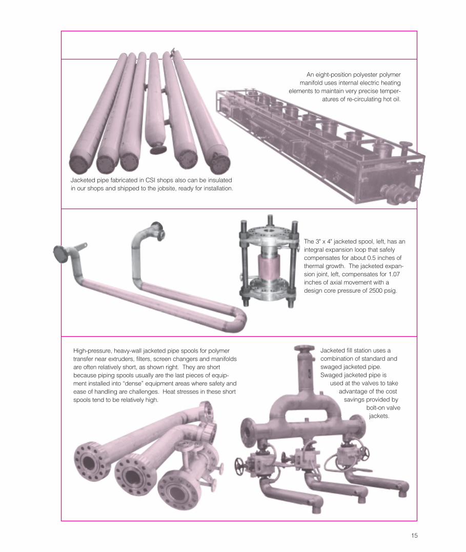
An eight-position polyester polymer manifold uses internal electric heating
elements to maintain very precise temper-atures of re-circulating hot oil.
High-pressure, heavy-wall jacketed pipe spools for polymertransfer near extruders, filters, screen changers and manifoldsare often relatively short, as shown right. They are shortbecause piping spools usually are the last pieces of equip-ment installed into “dense” equipment areas where safety andease of handling are challenges. Heat stresses in these shortspools tend to be relatively high.
Jacketed fill station uses acombination of standard andswaged jacketed pipe.Swaged jacketed pipe is
used at the valves to takeadvantage of the cost
savings provided bybolt-on valvejackets.
The 3" x 4" jacketed spool, left, has anintegral expansion loop that safelycompensates for about 0.5 inches ofthermal growth. The jacketed expan-sion joint, left, compensates for 1.07inches of axial movement with adesign core pressure of 2500 psig.
Jacketed pipe fabricated in CSI shops also can be insulatedin our shops and shipped to the jobsite, ready for installation.
Preparing quotations at CSI is similar to methods used by allfabricators. When the customer’s bid package comes in, it isassigned to an engineer or designer who starts the reviewprocess of specifications and drawings. Depending on thecomplexity, several reviews by different CSI personnel may beused to make sure there are no surprises.
Material prices are obtained from takeoffs cycledthrough Purchasing. Manhours for fabrication and welding,engineering, inspection and testing, and painting, if required,are estimated.
A review team meets to go over the accumulated num-bers. The team considers alternate material choices, fabrica-tion methods, even alternative designs that may cut expensesout of the project. The customer’s need date in light of CSI’sproduction schedule is also reviewed. The quotation thengoes to the customer. If the review team thinks that alternatesuggestions have merit, these suggestions are included in the
quotation with approximations of potential savings. For fast-track projects proceeding without completed
isometric or plan & elevation drawings, CSI has developed asimple, very accurate unit pricing schedule that allows thecustomer’s design group to quickly and easily determine thefinal price of any jacketed spool that contains a variety of fit-tings, connectors, and instrument taps. The unit pricing infor-mation is based on the customer’s design criteria of materials,schedules and operating conditions and any unique designdetails.
Depending on the customer’s needs, CSI prepares quo-tations for a variety of engineering services, ranging from on-site piping layouts and routings to complete turnkey pack-ages. When work scopes are not sufficiently defined to pro-vide lump-sum quotations, unit or manhours pricing can beprovided. Our preference, however, is to provide our cus-tomers with fixed, lump-sum proposals whenever practical.
16
CSI Engineering Services
Jacketed pipe is very unforgiving. Mistakes are difficult andexpensive to correct.
Several years ago, after learning this lesson the hardway, we promised ourselves to expand our engineering capa-bilities and our process heating knowledge. It was obviousthat we needed to be on a higher technical plateau, to makesure our customers were getting their money’s worth.
Today, we don’t have all the answers, to be sure. We dohave, however, confidence in our products, our craftsmen, andin our engineering abilities to help our customers optimize theirjacketed piping systems. Our engineering staff stands ready to:1. Make cost-saving suggestions on material selections and
types of jacketing needed. 2. Help designers find the optimum piping configuration for
the process.3. Assist with pressure drop analysis of process
heating fluids.4. Perform macro and micro system thermal analysis,
considering processes, heating fluids, and pipe construction details.
5. Perform stress analysis on piping systems and individual spool designs.
6. Provide on-site review of piping layouts and routing, andheating medium routing and tie-ins.
7. Organize and execute turnkey piping projects, from con-cept to customer sign-off.
We are prepared and committed to give jacketed pipingthe attention that critical equipment deserves.
Everything Starts With A Quotation.
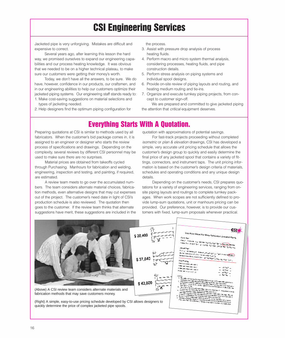
(Above) A CSI review team considers alternate materials and fabrication methods that may save customers money.
(Right) A simple, easy-to-use pricing schedule developed by CSI allows designers toquickly determine the price of complex jacketed pipe spools.

17
Pay Attention To Stress.As a general rule, all jacketed piping systems should be stressanalyzed. After CSI receives system drawings we reviewthem, looking for potential trouble spots. We do not performstress analysis unless specifically authorized by the customer.However, when we see conditions that we think deserve closerscrutiny, we notify the customer of our observations, suggest-ing that the customer double check the condition with the system designers, or authorize CSI to proceed with analysis.The following conditions are typical of the types of design conditions that “raise red flags” at CSI:
● Tight pipe routing with few changes in direction that mayresult in a very rigid piping system without enough flexibility.
● Piping construction that uses different materials for the coreand jacket. The differential thermal expansions of the materials may cause unacceptable stress levels.
● Systems with wide temperature differences between thecore and jacket. Example: Buried containment piping withthe core at elevated temperature and the jacket at or nearthe temperature of the earth.
● Piping systems that operate in cyclic service (as in batchprocesses).
● Piping arrangements that appear to place lateral or axialloads on equipment nozzles that may not be capable ofwithstanding the loads. Examples: Pumps, reactors, vesselson load cells, heat exchangers, and filters.
● Unusual construction details that may have been dictated byequipment locations with unusual tie-ins. Example:Jacketed spools with little or no tangential runouts on elbows.
Depending on the service conditions, individual designdetails such as flange attachments, jacket terminations, coretaps, spacer design and locations may need scrutiny. Thisneed for scrutiny goes up with increasing service temperaturesor widening temperature differential between the core and jacket.
The point to remember is that when jacketed pipe isconsidered to be critical equipment, it needs to be stress analyzed – whether the intended use is asphalt transfer orCategory M service.
Good stress analysis is an important factor in designing jacketed piping systems. CSI engineers use traditional analy-sis software supported with two equally important elements: Knowledge and experience.
All system drawings released to CSI for production of individual spool drawings are reviewed by CSI project engineers for potential stress problems.
Individual weld joints of specific constructions need stressanalysis (micro analysis) when the likely possibility of extremeoperating conditions exists. Examples: Processing tempera-tures substantially exceeding heating medium temperatures,and traps of condensate causing wide temperature differentialbetween core and jacket.

18
Where Does The Heat Go?Jacketed piping may be considered a systemthat maintains a process temperature, or it maybe considered a system of single-tube heatexchangers.
If the process picks up or gives up heat,the system is performing the function of a heatexchanger.
Normally, jacketed piping systems aredesigned for temperature maintenance. That is,the process temperature should remain very uni-form as it flows through the core piping. It needsto operate as a heat exchanger only during start-up or recovery from emergency shut-downs.
In reality, the dynamics of jacketed pipingduring normal operation are truly those of a heatexchanger, with the process accepting and giving up incremental energy based on the tem-perature differences between it and the heatingfluid. The rate of heat transfer to and from theprocess, of course, depends on several factorssuch as film coefficients, velocities, and thermalconductivities of the several components.
To illustrate, consider a 2" x 3" jacketed piping systemapproximately 220 feet long. The process is a hydrocarbonresin. System properties and operating data needed foranalysis are listed in the accompanying table, center.Assume a water-glycol heating medium.
Using finite difference modeling techniques developedin-house and commercial analytical software, CSI engineersanalyze heat transfer mechanisms that occur in systems likethis, to help process designers establish specification andprocedural parameters. The graph below depicts a system
analyzed with the heating medium flowingconcurrently with the process. Note that theprocess temperature increases and becomeshotter than the heating medium. Althoughthe process temperature leaving the systemequals the entrance temperature, a 3%process temperature swing occurred. If amaterial is heat sensitive and unable to toleratetemperatures above a certain value, the heat-ing medium temperature must be reduced.In concurrent flow, this type of exchangemechanism occurs routinely. And the level ofthermal analysis needed depends on thesensitivity of the process to temperature, or“time-at-temperature.”
As a precaution, we also analyze no-flowconditions to see what happens whenprocess flow stops.
The modeling tools used by CSI demon-strate the dynamic temperature profiles ofsystems under various operating conditions.Heating medium temperatures, flow patterns,
and process flow rates can be tested. Similar modeling toolshave been developed to study the thermal performance of spe-cific piping details with certain processes and heating media.
These modeling services are available to CSI cus-tomers. We recommend that designers consider these services whenever process temperature envelopes are verynarrow, equipment layouts dictate specific constructions thatmay create chill spots, and when newer processes must be incorporated into older systems with fixed heating medium parameters.
Process FluidMolecular Wt.
Specific GravitySpecific Heat
Flow rate Entrance temp.
Viscosity Conductivity
Heating MediumType & Properties
TemperaturePressure
Flow rate (liquid)Ambient Temp.
InsulationType
ThicknessPiping Materials Core & wall thk.
Jacket & wall thk.
CSI has developed computerized heat transfer tools that can aiddesigners in establishing heating specifications and proceduralparameters for piping systems.
The finite difference heat transfer modeling used by CSI incorpo-rates the various fluid properties of the medium and process, aswell as specific construction techniques.

19
CSI has developed data and procedural techniques for approximating pressure drops in jacketed piping systems, based on component flow tests
and conventional mathematical models.
The pressure drop through jumpover connections can be a significant component of the system’s total head requirement.
This 3" x 5" jacketed spool uses a 2.5" tangential inlet jumpoverto minimize head loss.
Pressure Drops In Jacketed Piping.Pressure drop analysis can be an arduous task in a jacketedpiping system, especially when narrow temperature windowsmust be maintained. Often, the cumulative pressure dropthrough heating medium jumpovers is greater than the dropthrough the piping spools. This results mainly from the sharpangles the heating fluids must traverse as they enter and exitthe jacketed spool.
To arrive at an optimal design, a thermal analysis of thesystem may be necessary, to determine not only how muchheat is given up to the atmosphere, but also how much heatis absorbed by the process. Determining accurate heatloads is important for assessing accurate heating mediumflow or capacity requirements.
In liquid heating systems, designers have several pressure-reducing options to consider when pump headsand capacities are restricted:1. Increase the nominal size of the jumpover.2. Use tangential entrances to feed the heating fluid into
the spool.3. Increase the size of the jacket pipe, allowing lower flow
rates (and lower pressure drops) through the core/jacketannulus.
4. Increase the number of circuits feeding the system fromthe main heating fluid header.
In systems using vapor as the heating medium, circuitlengths, trap size, start-up demand, as well as total heat loadsduring equilibrium operating conditions need to be considered.
The CSI engineering staff conducts on-going tests todetermine heating medium pressure drop losses through various components used in process temperature control.
Pressure drop analysis, pump and trap sizing, circuitlayout, and jumpover design are services the CSI engineeringstaff routinely perform. The cost of these services is nominal,based on the complexity of the system and the degree ofdocumentation required.

20
CSI Turn-Key ServicesRapidly changing business conditions have compelled manyprocessing companies to focus their energies on reducingproduction costs... and engineering staffs. Similarly, manyengineering houses, in efforts to speed up project responsetimes and maintain maximum flexibility, are streamlining theirproject management teams, looking to outside sources forspecialized talents.
In this fluid business climate, CSI stands ready with anarray of highly specialized skills and capabilities that help cus-tomers keep jacketed piping projects on time, and on budget.
Our commitment to ourselves and to the processingindustry is to design the right jacketed piping systems, thenfabricate and install them. From start to finish, we willinglyaccept responsibility for your jacketed piping system. Our
basic focus is simple: run a successful business by satisfyingour customers.
CSI turn-key projects range in dollar value from$35,000 to $3.5 million. The projects cover many construc-tions, from heavy-wall polymer piping to light-wall tubing fordairy products. We have ambitions to assume responsibilitiesfor larger projects.
We urge our customers and potential customers to visitour shops – to see first hand our commitment in action. Tosee and talk to...● An engineering staff with the experience to anticipate a
vast assortment of problems relating to jacketed pipe – astaff that works with heated processes every day; monthby month; year by year.
● Skilled, capable fabricators and welders who build andinstall jacketed piping systems, and who individually haverecorded thousands of safe manhours in developing thehighest standards of craftsmanship.
Some customers tell us that it’s CSI’s demonstratedknowledge, experience and craftsmanship that give us anedge. In reality, any advantage we might enjoy, howeversmall, comes from hard work toward one purpose: a satisfiedcustomer.
CSI has provided turn-key installations for awide range of heatedprocesses: Acrylic acid,bitumens, BPA, benzoicacid, caprolactam, DMT,EVA, phthalic anhydride,nylon and polyester poly-mers, viscose, sulfur,and several food items.All of these projectswere performed underlump-sum contracts. Thephoto above and thephoto left are typicalexamples of CSI turn-key projects.
CSI installation crews are the same team of engineers, fabrica-tors, and supervisors who design and produce jacketed pipingsystems in our shops at Charlotte, NC, USA.