Embed Size (px)
Citation preview
P. S. Yang A. M. Wolde--'finsae L. F. Greimann
Nonlinear Finite Eleuient Study of Piles in Integral Abutment Bridges
Part2
September 1982
Iowa DOT Project HR-227 ERi Project 1501
ISU-ERI-Ames-83068
Sponsored by the Iowa Department of Transportation, Highway Division, · and the Iowa Highway Research Board
--. College of Engineering
Iowa State Universitv
The opinions, findings, and conclusions expressed in this publication are those of the authors and not necessarily those of the Highway Division of the Iowa Department of Transportation.
'D c: .. ,. ---- -.... w. 1ang
A. M. Wolde-Tinsae L. F. Greimann
Final Report
Nonlinear Finite Elem.ent Study of Piles in Integral Abutm.ent Bridges
Submitted to the Highway Division, Iowa Department of Transportation
Iowa DOT Project HR-227 ERi Project 1501
September 1982
Department of Civil Engineering Engineering Research Institute
iii
TABLE OF CONTENTS
ABSTRACT
LIST OF FIGURES
LIST OF TABLES
1. INTRODUCTION
1.1. Statement of the Problem
1.2. Background
1.3. Objective and Scope
2. LITERATURE REVIEW
2.1. Analytical Studies
2.2. Experimental Studies
2.2.1. South Dakota Tests 2.2.2. North Dakota Tests
3. SURVEY OF CURRENT PRACTICE FOR SKEWED BRIDGES WITH INTEGRAL ABUTMENTS
3.1. Method of Investigation
3.2. Trends of Response
3.3. Summary and Conclusions
4. INFLUENCE OF DIFFERENT FACTORS ON BEHAVIOR OF INTEGRAL ABUTMENT BRIDGES
4.1. Integral Abutment Idealization
4.2. Influence of Rotation at the Pile Head
4.3. Effect of Predrilled Oversized Hole
4.4. Layered Soils
v
vii
xi
1
1
3
4
5
5
6
7 13
19
19
20
26
29
29
31
47
66
5.
6.
7.
8.
iv
SUMMARY, CONCLUSIONS, AND RECOMMENDATIONS FOR FURTHER STUDY
5.1. Summary
5.2. Conclusions
5.3. Recommendations for Further Study
ACKNOWLEDGEMENT
REFERENCES
APPENDICES
8.1. Questionnaire for Survey of Current Practice on Skewed Bridges with Integral Abutments and Swnmary
Page
85
85
89
92
95
97
101
of Responses 103
8.2. Listing of Program 117
v
ABSTRACT
The highway departments of the states which use integral abutments
in bridge design were contacted in order to study the extent of integral
abutment use in skewed bridges and to survey the different guidelines
used for analysis and design of integral abutments in skewed bridges.
The variation in design assumptions and pile orientations among the
various states in their approach to the use of integral abutments on
skewed bridges is discussed. The problems associated with the treatment
of the approach slab, backfill, and pile cap, and the reason for using
different pile orientations are summarized in the report.
An algorithm based on a state-of-the-art nonlinear finite element
procedure previously developed by the authors was modified and used to
study the influence of different factors on behavior of piles in
integral abutment bridges. An idealized integral abutment was intro
duced by assuming that the pile is rigidly cast into the pile cap and
that the approach slab offers no resistance to lateral thermal expansion.
Passive soil and shear resistance of the cap are neglected in design.
A 40-foot H pile (HP 10 x 42) in six typical Iowa soils was
analyzed for fully restrained pile head and pinned pile head. According
to numerical results, the maximum safe length for fully restrained
pile head is one-half the maximum safe length for pinned pile head.
If the pile head is partially restrained, the maximum safe length will
lie between the two limits.
The numerical results from an investigation of the effect of
predrilled oversized holes indicate that if the length of the pre-

vi
drilled oversized hole is at least 4 feet below the ground, the vertical
load-carrying capacity of the H pile is only reduced by 10 percent for
4 inches of lateral displacement in very stiff clay. With no predrilled
oversized holef the pile failed before the 4-inch lateral displacement
was reached. Thus, the maximum safe lengths for integral abutment
bridges may be increased by predrilling.
Four different typical Iowa layered soils were selected and used
in this investigation. In certain situations, compacted soil (> SO
blow count in standard penetration tests) is used as fill on top of
natural soil. The numerical results showed that the critical conditions
will depend on the length of the compacted soil. If the length of the
compacted soil exceeds 4 feet, the failure mechanism for the pile is
similar to one in a layer of very stiff clay. That is, the vertical
load-carrying capacity of the H pile will be greatly reduced as the
specified lateral displacement increases.
viii
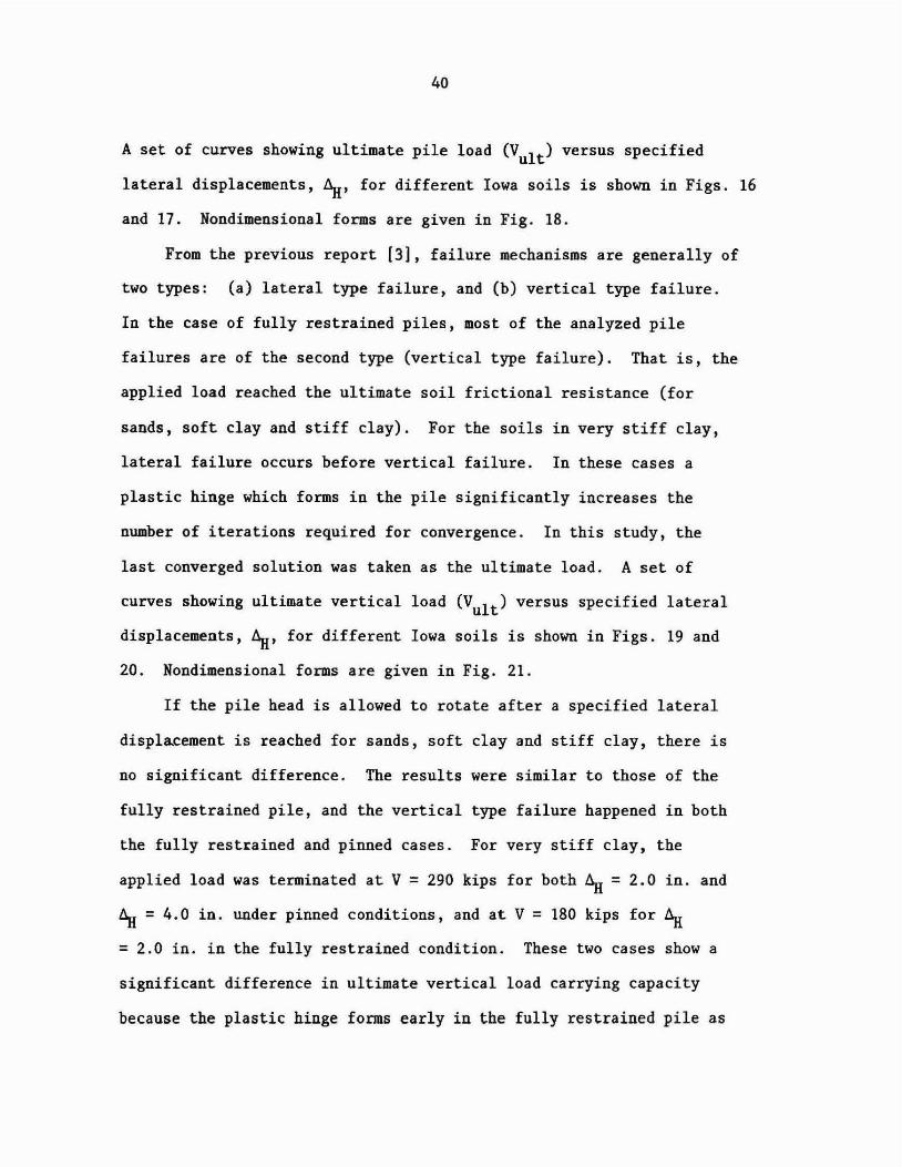
Fig. 16. Ultimate vertical load versus specified lateral displacements in clay with pinned condition at the pile head. 41
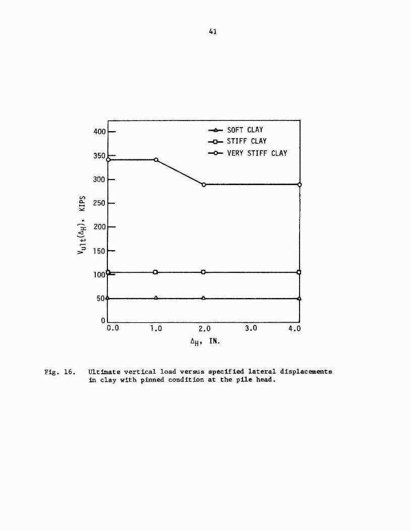
Fig. 17. Ultimate vertical load versus specified lateral displacements in sand with pinned condition at the pile head. 42
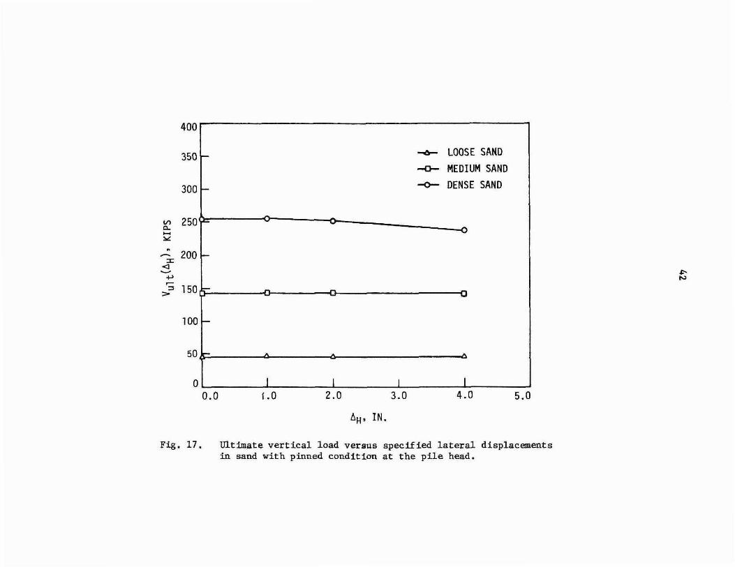
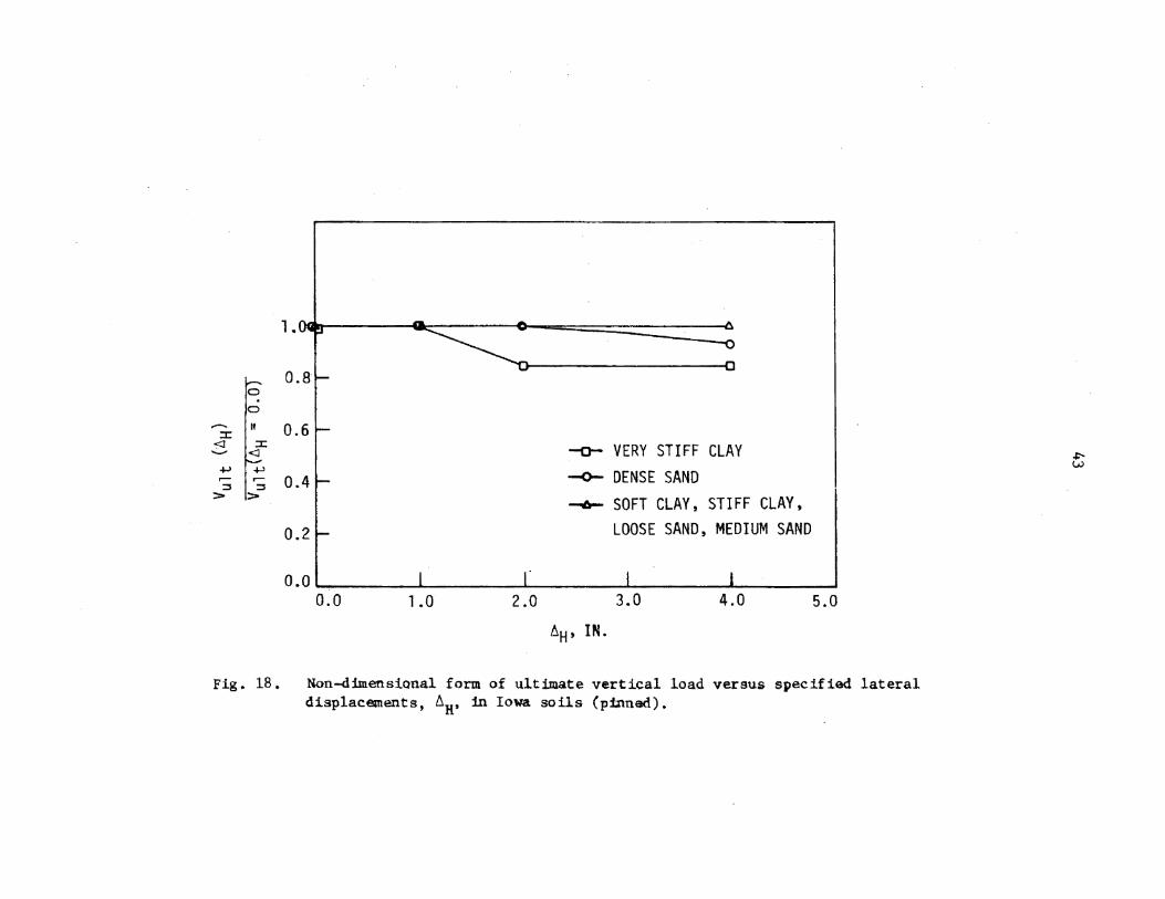
Fig. 18. Non-dimensional form of ultimate vertical load versus specified lateral displacements, 6ir' in Iowa soils (pinned). 43
Fig. 19. Ultimate vertical load versus lateral specified displacements with fully restrained pile head (clay). 44
Fig. 20. Ultimate vertical load versus lateral specified displacements with fully restrained pile head (sand). 45
Fig. 21. Non-dimensional forms of ultimate vertical load versus lateral specified displacements, L11' in Iowa soils (with fully restrained pile head). 46
Fig. 22. A detailed design for predrilled oversized hole. 48
Fig. 23. Vertical load-settlement curves with specified lateral displacements, ~ (O, 1, 2, 4 in.), for very stiff clay with 2 foot long predrilled oversized hole without sand fill. 50
Fig. 24. Vertical load-settlement curves with specified lateral displacements,~ (O, 1, 2, 4 in.), for very stiff clay with 4 foot long predrilled oversized hole without sand fill. 51
Fig. 25. Vertical load-settlement curves with specified lateral displacements, ~ (0, 1, 2, 4 in.), for very stiff clay with 6 foot long predrilled oversized hole without sand fill. 52
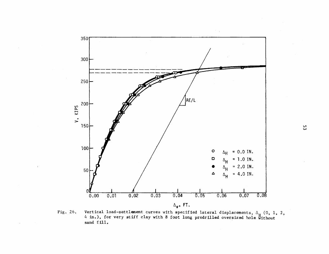
Fig. 26. Vertical load-settlement curves with specified lateral displacements, flu (O, 1, 2, 4 in.), for very stiff clay with 8 f8ot long predrilled oversized hole without sand fill. 53
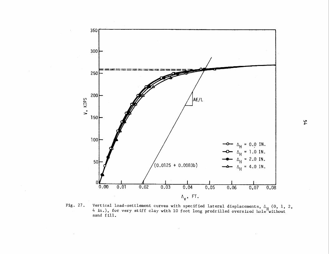
Fig. 27. Vertical load-settlement curves with specified lateral displacements, D.u (O, 1, 2, 4 in.), for very stiff clay with 10 foot long predrilled oversized hole without sand fill. 54
ix
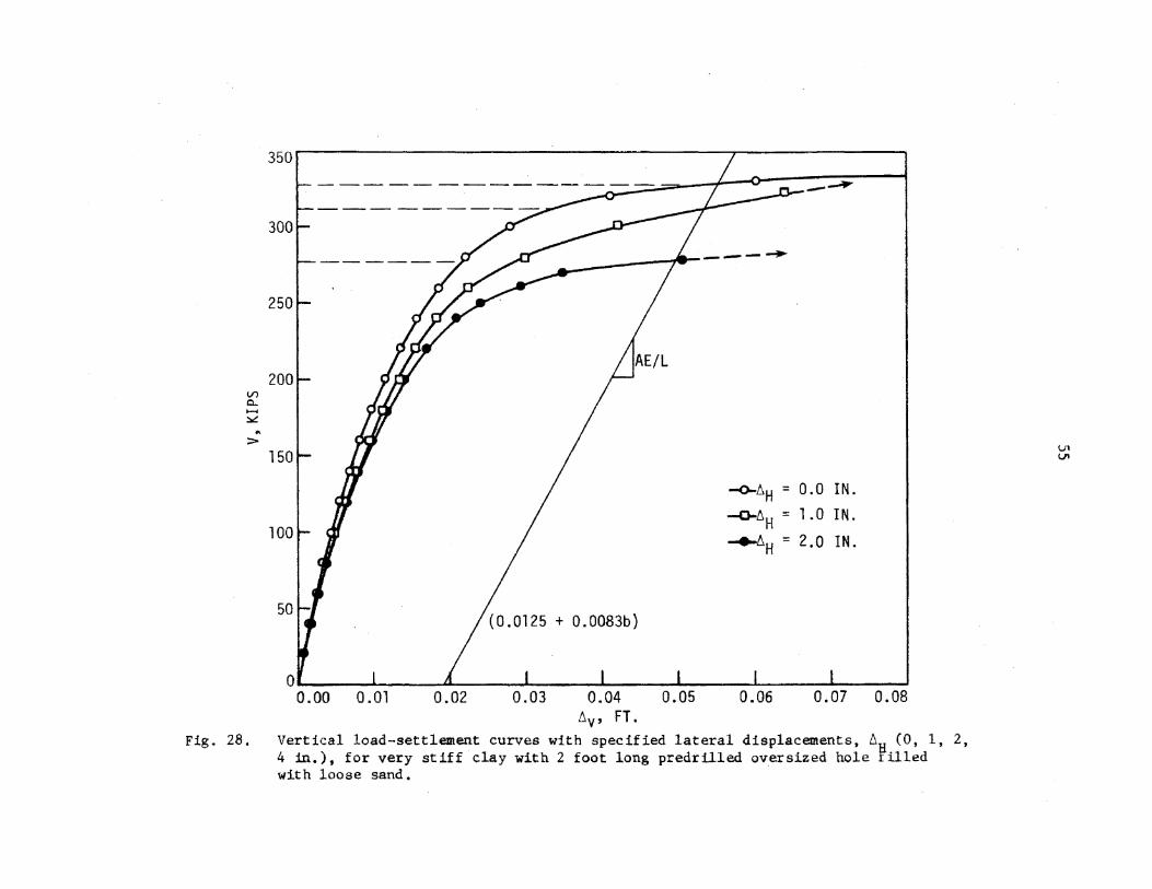
Fig. 28. Vertical load-settlement curves with specified lateral displacements, ~ (O, 1, 2, 4 in.), for very stiff clay with 2 foot long predrilled oversized hole filled with loose sand. 55
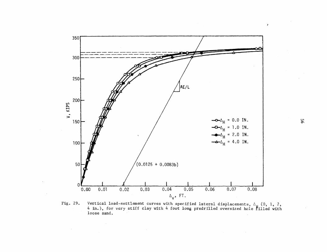
Fig. 29. Vertical load-settlement curves with specified lateral displacements,~ (O, 1, 2, 4 in.), for very stiff clay with 4 foot long predrilled oversized hole filled with loose sand. 56
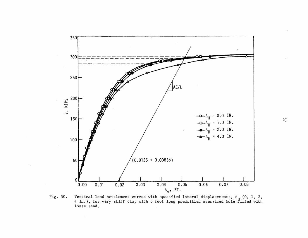
Fig. 30. Vertical load-settlement curves with specified lateral displacements,~ (O, 1, 2, 4 in.), for very stiff clay with 6 foot long predrilled oversized hole filled with loose sand. 57
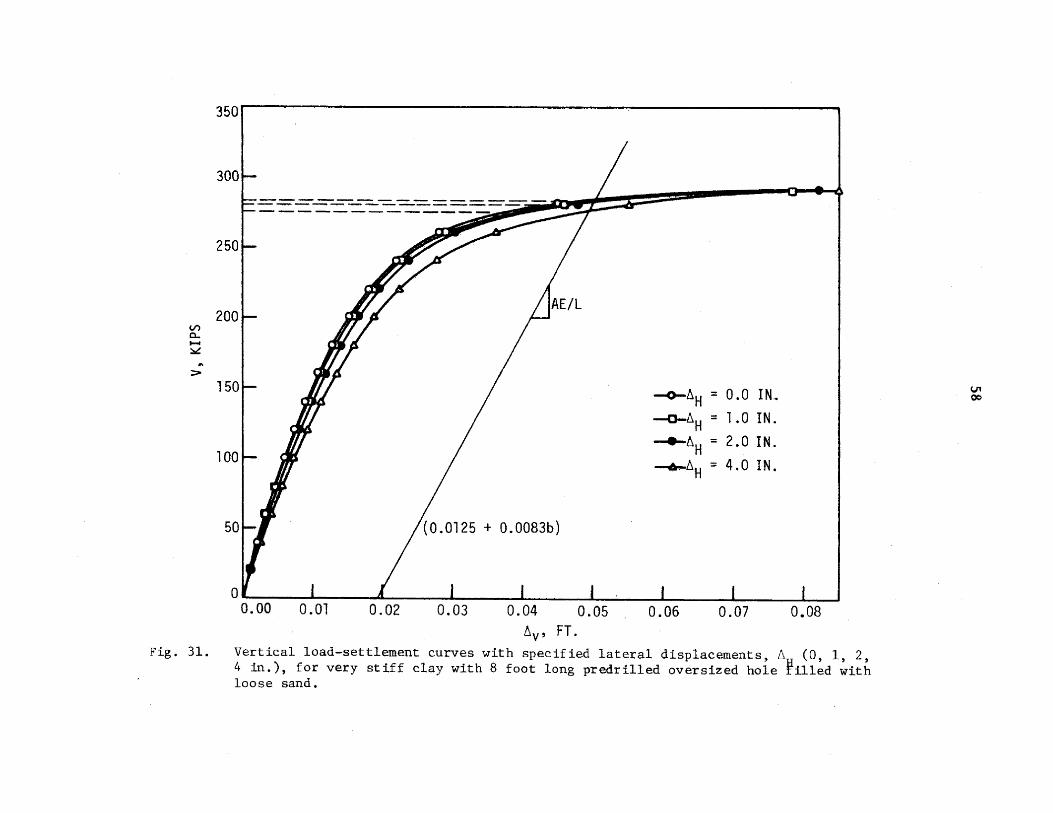
Fig. 31. Vertical load-settlement curves with specified lateral displacements,~ (O, 1, 2, 4 in.), for very stiff clay with 8 foot long predrilled oversized hole filled with loose sand. 58
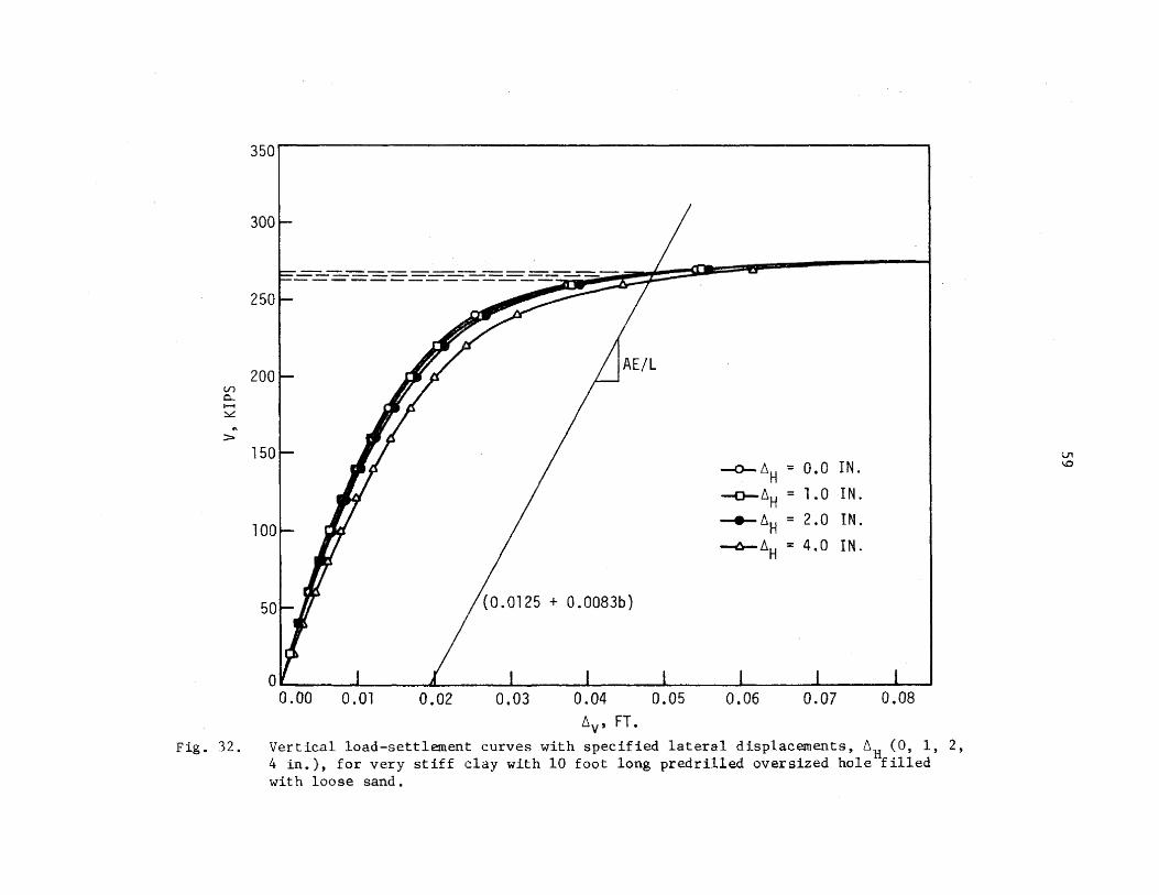
Fig. 32. Vertical load-settlement curves with specified lateral displacements, flu (0, 1, 2, 4 in.), for very stiff clay with 10 ¥oot long predrilled oversized hole filled with loose sand. 59
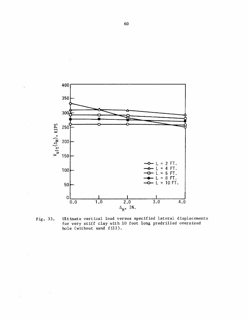
Fig. 33. Ultimate vertical load versus specified lateral displacements for very stiff clay with 10 foot long predrilled oversized hole (without sandfill). 60
·Fig. 34. Ultimate vertical load versus specified lateral displacements for very stiff clay with 10 foot long predrilled oversized hole (with loose sand). 61
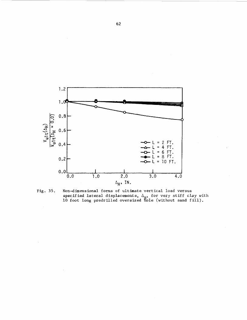
Fig. 35. Non-dimensional forms of ultimate vertical load versus specified lateral displacements, 6u, for very stiff clay with 10 foot long predrilfed oversized hole (without sandfill). 62
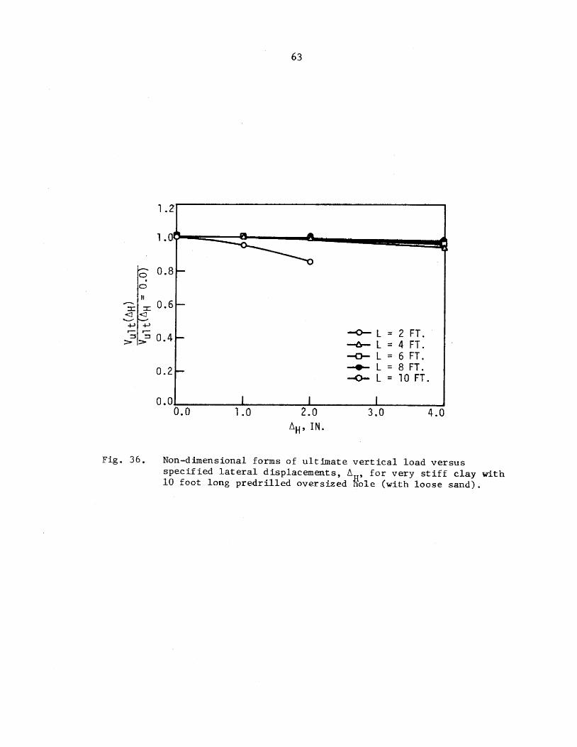
Fig. 36. Non-dimensional forms of ultimate vertical load versus specified lateral displacements, !ia, for very stiff clay with 10 foot long predrilfed oversized hole (with loose sand). 63
Fig. 37. Vertical load-settlement curves with specified lateral displacements,~ (0, 1, 2, 3, 4 in.), for western Iowa soil. 71
x
Fig. 38. Vertical load-settlement curves with specified lateral displacements, ~ (0, 1, 2, 4 in.), for eastern Iowa soil. 72
Fig. 39. Vertical load-settlement curves with specified lateral displacements, ~ (0, 1, 2, 4 in.), for southern Iowa soil. 73
Fig. 40. Vertical load-settlement curves with specified lateral displacements, ~ (O, 1, 2, 4 in.),' for northern Iowa soil. 74
Fig. 41. Ultimate vertical load versus specified lateral displacements for typical Iowa layered soils. 75
Fig. 42. Non-dimensional forms of ultimate vertical load versus specified lateral displacements, ~' in typical Iowa layered soil. 76
Fig. 43. Vertical load-settlement curves with specified lateral displacements, ~ (0, 1, 2, 4 in.), for western Iowa soil with 4 foot long compacted soil. 78
Fig. 44. Vertical load-settlement curves with specified lateral displacements, ~ (0, 1, 2, 4 in.), for southern Iowa soil with ~ foot long compacted soil. 79
Fig. 45. Vertical load-settlement curves with specified lateral displacements, ~ (0, 1, 2, 4 in.), for eastern Iowa soil with 4 foot long compacted soil. 80
Fig. 46. Vertical load-settlement curves with specified lateral displacements, fl..i (0, 1, 2, 4 in.), for northern Iowa soil with ~ foot long compacted soil. 81
Fig .. 47. Ultimate vertical load versus specified lateral displacements for typical Iowa layered soils with 4 foot long compacted soil. 82
Fig. 48. Non-dimensional forms of ultimate vertical load versus specified lateral displacements, ~' for typical Iowa layered soils with 4 foot long compacted soil. 83
xi
LIST OF TABLES
Table 1. The reduced ultimate vertical load carrying capacity in cases (a), (b) and (c) under specified lateral displacements.
Table 2. Typical Iowa layered soils.
Table 3. Modified Iowa layered soils without compacted soil.
Table 4. Modified Iowa layered soils with 4 foot long compacted soil.
65
68
69
69
I. INTRODUCTION
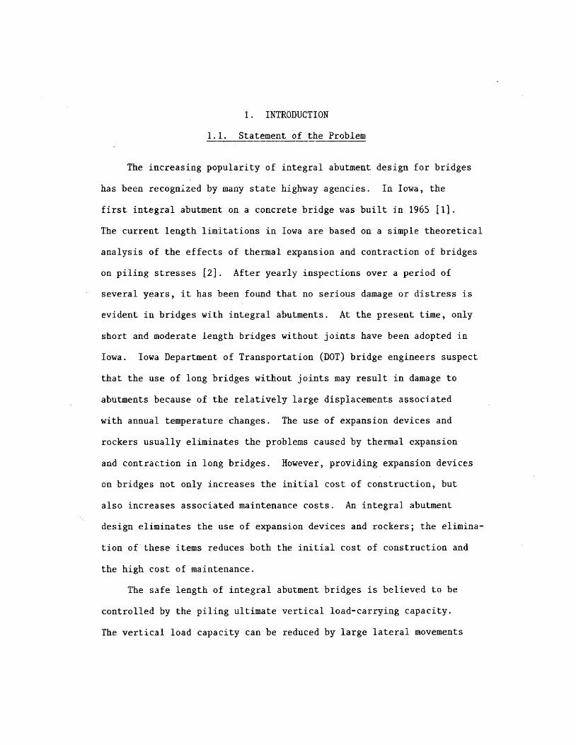
1.1. Statement of the Problem
The increasing popularity of integral abutment design for bridges
has been recognized by many state highway agencies. In Iowa, the
first integral abutment on a concrete bridge was built in 1965 [l].
The current length limitations in Iowa are based on a simple theoretical
analysis of the effects of thermal expansion and contraction of bridges
on piling stresses [2]. After yearly inspections over a period of
several years, it has been found that no serious damage or distress is
evident in bridges with integral abutments. At the present time, only
short and moderate length bridges without joints have been adopted in
Iowa. Iowa Department of Transportation (DOT) bridge engineers suspect
that the use of long bridges without joints may result in damage to
abutments because of the relatively large displacements associated
with annual temperature changes. The use of expansion devices and
rockers usually eliminates the problems caused by thermal expansion
and contraction in long bridges. However, providing expansion devices
on bridges not only increases the initial cost of construction, but
also increases associated maintenance costs. An integral abutment
design eliminates the use of expansion devices and rockers; the elimina
tion of these items reduces both the initial cost of construction and
the high cost of maintenance.
The safe length of integral abutment bridges is believed to be
controlled by the piling ultimate vertical load-carrying capacity.
The vertical load capacity can be reduced by large lateral movements
2
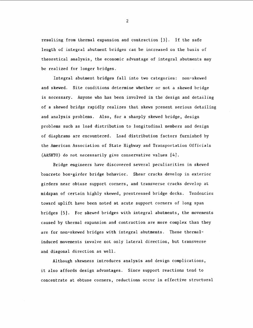
resulting from thermal expansion and contraction [3]. If the safe
length of integral abutment bridges can be increased on the basis of
theoretical analysis, the economic advantage of integral abutments may
be realized for longer bridges.
Integral abutment bridges fall into two categories: non-skewed
and skewed. Site conditions determine whether or not a skewed bridge
is necessary. Anyone who has been involved in the design and detailing
of a skewed bridge rapidly realizes that skews present serious detailing
and analysis problems. Also, for a sharply skewed bridge, design
problems such as load distribution to longitudinal members and design
of diaphrams are encountered. Load distribution factors furnished by
the American Association of State Highway and Transportation Officials
(AASHTO) do not necessarily give conservative values [4J.
Bridge engineers have discovered several peculiarities in skewed
concrete box-girder bridge behavior. Shear cracks develop in exterior
girders near obtuse support corners, and transverse cracks develop at
midspan of certain highly skewed, prestressed bridge decks. Tendencies
toward uplift have been noted at acute support corners of long span
bridges (5). For skewed bridges with integral abutments, the movements
caused by thermal expansion and contraction are more complex than they
are for non-skewed bridges with integral abutments. These thermal
induced movements involve not only lateral direction, but transverse
and diagonal direction as well.
Although skewness introduces analysis and design complications,
it also affords design advantages. Since support reactions tend to
concentrate at obtuse corners, reductions occur in effective structural
3
spans. The thick end diaphrams act to reduce longitudinal stresses in
the superstructure. Hence, possibilities exist for material savings
by refining structural analysis [S].
1.2. Background
Prior to World War II, most bridges with an overall length of SO
feet or more were constructed with some form of expansion joints.
Periodic inspection of these bridges revealed that expansion joints
tended to freeze and close, and did not operate as intended. After
observing the successful performance of many older bridges either
constructed without joints or performing with inoperative joints,
several states have elected to design and construct short and moderate
length bridges without expansion joints.
Today more than half of the state highway agencies have developed
design criteria for bridges without expansion joints. These design
criteria are based on years of experience in integral abutment bridge
design. This development led to wide variations in design criteria
for integral abutments bridges from state to state. In July 1972,
South Dakota State University issued a report sununarizing the results
of an investigation on stresses induced by thermal movements in the
girder and upper portion of steel bearing piles of integral abutment
type bridges [11. In November 1981, North Dakota State University
issued a report on a study which was conducted to observe lateral
movements resulting from annual temperature variations and monitor the
temperature-induced piling stresses [6]. In February 1982, Iowa State

4
University published a report entitled "Nonlinear Pile Behavior in
Integral Abutment Bridges" by A. M. Wolde-Tinsae, L. F. Greimann, and
P. S. Yang. This report swnmarized the variation in design assumptions
and length limitations among the various states in their approach to
the use of integral abutments. Also, an algorithm based on a state-of
the-art nonlinear finite element procedure was developed and used to
study piling stresses and pile-soil interaction in integral abutment
bridges.
1.3. Objective and Scope
The present research is part of an ongoing research project on
nonlinear pile behavior in integral abutment bridges [3]. As part of
this investigation, the highway departments of different states which
use integral abutments in bridge design were contacted in order to
study the extent of integral abutment use in skewed bridges, and to
survey the different guidelines used for analysis and design of integral
abutments for skewed bridges. The influence of different factors on
behavior of integral abutment bridges, e.g., restraint of the pile
head, predrilled oversized hole effect, and pile behavior in different
soil profiles, have been investigated by means of a state-of-the-art
nonlinear finite element model. The results and conclusions are
summarized in this report.
5
2. LITERATURE REVIEW
2.1. Analytical Studies
The piles of integral abutment bridges subjected to lateral
movements caused by thermal expansion and contraction can be treated
as piles subjected to lateral loads. The problem of a pile subjected
.to lateral loading is one of a class of problems concerning the inter
action of soils and structures. The solution of such problems generally
involves the use of iterative techniques since soil response is a
nonlinear function of the structure's deflection.
In the past, analysis and design of laterally loaded piles were
primarily empirical, based on data from full-scale tests of laterally
loaded piles [7,8]. However, in recent years, extensive research and
development have been undertaken to predict theoretically the behavior
of a laterally loaded pile [9-11].
In a previous study by the authors [3], an algorithm based on a
state-of-the-art nonlinear finite element procedure was developed and
used to study piling stresses and pile-soil interaction in integral
abutment bridges. The finite element idealization consists of a
one-dimensional idealization for the pile and nonlinear springs for
the soil. Important parameters for analysis are pile and soil charac
teristics. On the basis of a literature review, it was decided to
represent pile characteristics by beam-column elements with geometric
and material nonlinearities, and soil characteristics by lateral
resistance-displacement (p-y), load-slip (f-z), and load-settlement
(q-z) curves. An idealized soil model (modified Romberg-Osgood Model)
0
was introduced to obtain the tangent stiffness of the nonlinear spring
elements. The report includes a discussion of details pertaining to
the derivation of the incremental finite element updated Langrangian
formulation, including material and geometric nonlinearities, and the
solution algorithm, involving incremental and iterative techniques
used in the study [3]. A computer program developed for this study
(Yang 5) is provided in Appendix 8.2.
2.2. Experimental Studies
Numerous experimental research projects on piles subjected to
vertical and/or lateral loading in the laboratory or field have been
performed in recent years. Seed and Reese studied small, displacement
type friction pile which was driven into a nonsensitive clay. In that
study, the load-distribution curves and load-slip curves (f-z curves)
for a friction pile were first defined [12]. Matlock [13], Reese and
Welch [14], and Reese, Cox, and Koop (15] also performed experimental
work on soft clay, stiff clay, and sand, respectively, to predict
lateral resistance-displacement curves (p-y curves) for laterally
loaded piles. A curve describing the load-settlement behavior of the
pile's tip was given by Vijayvergiya [16]. Numerous methods exist for
predicting these curves for different soil types. A brief discussion
over some of these methods is given in our previous report [3].
Many tests on instrumented piles subjected to vertical and/or
lateral loading in the field or laboratory have been performed [17-20].
In March 1973, a full-scale model representing the end portion of a
7
typical highw~y bridge was constructed and tested in four construction
stages by South Dakota State University [l]. During each stage, the
test specimen was subjected to a series of predetermined longitudinal
movements via hydraulic jacks to simulate expansion and contraction
caused by temperature changes. In August of 1979, an operational
county road bridge near Fargo, North Dakota was instrumented and
monitored for temperature-induced stresses by North Dakota State
University [6]. This study is being conducted by J. Jorgenson, Chairman
of the Civil Engineering Department, and is sponsored by the State
Highway Department. During one year of observation, monthly readings
were taken on the length of the bridge, the gap between backfill and
backside of abutment, etc. A preliminary report was published in
November 1981. A brief sunnnary of these two tests is given below.
2.2.1. South Dakota Tests
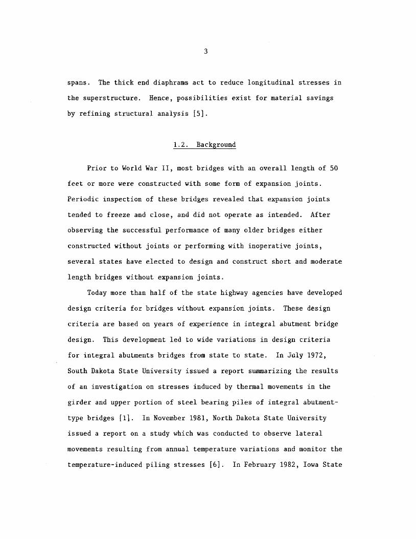
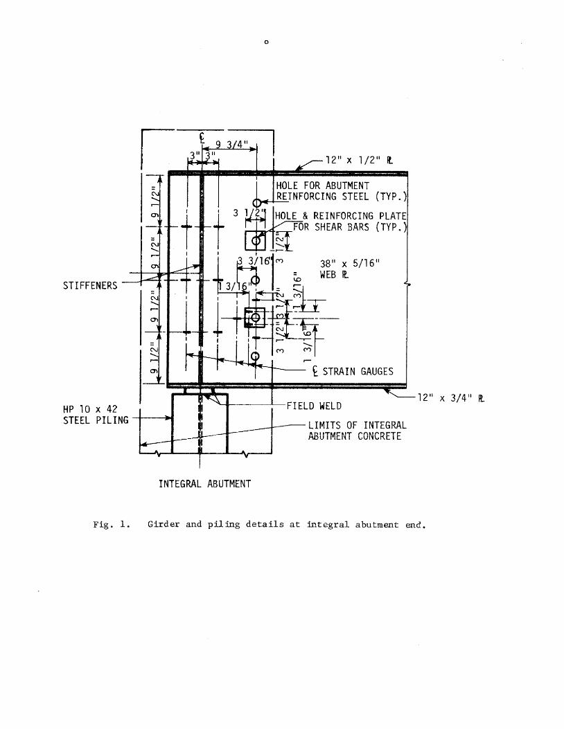
A full-scale model representing the end portion of a typical
highway bridge was constructed and tested in four stages:
Stage I: The girders were erected and welded to the bearing
piles (HP 10 x 42). See Fig. 1.
Stage II: The integral abutment was built and the concrete
attained its design strength.
Stage III: The deck slab was poured and the concrete attained
its design strength.
Stage IV: The granular backfill was placed.
For each stage the test specimen was subjected to a series of
predetermined longitudinal movements simulating thermal movements of
STIFFENERS
HP 10 x 42 STEEL PILING
-N
+ t
0
12 11 x 1/2 11 It
HOLE FOR ABUTMENT REINFORCING STEEL (TYP.)
ITH~-
-\()
38" x 5/16 11
WEB It
I ---- £ STRAIN GAUGES
---~-FIELD WELD
-- LIM ITS OF INTEGRAL ftnl t'Tl.tl""U"T f'\l"\llf'\nl""'TI"" MOUl~C~I LU~LKCIC
INTEGRAL ABUTMENT
12" x 3/4 11 ft.
Fig. 1. Girder and piling details at integral abutment end.
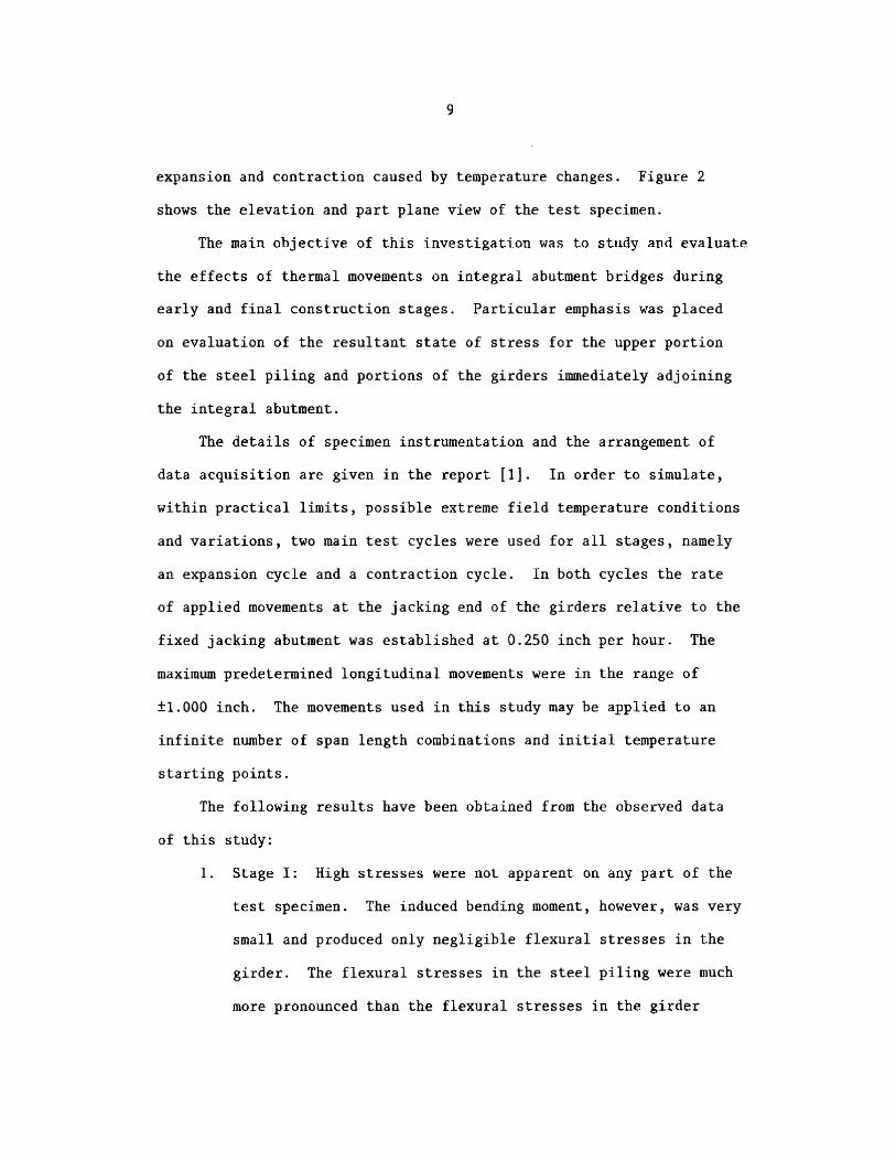
9
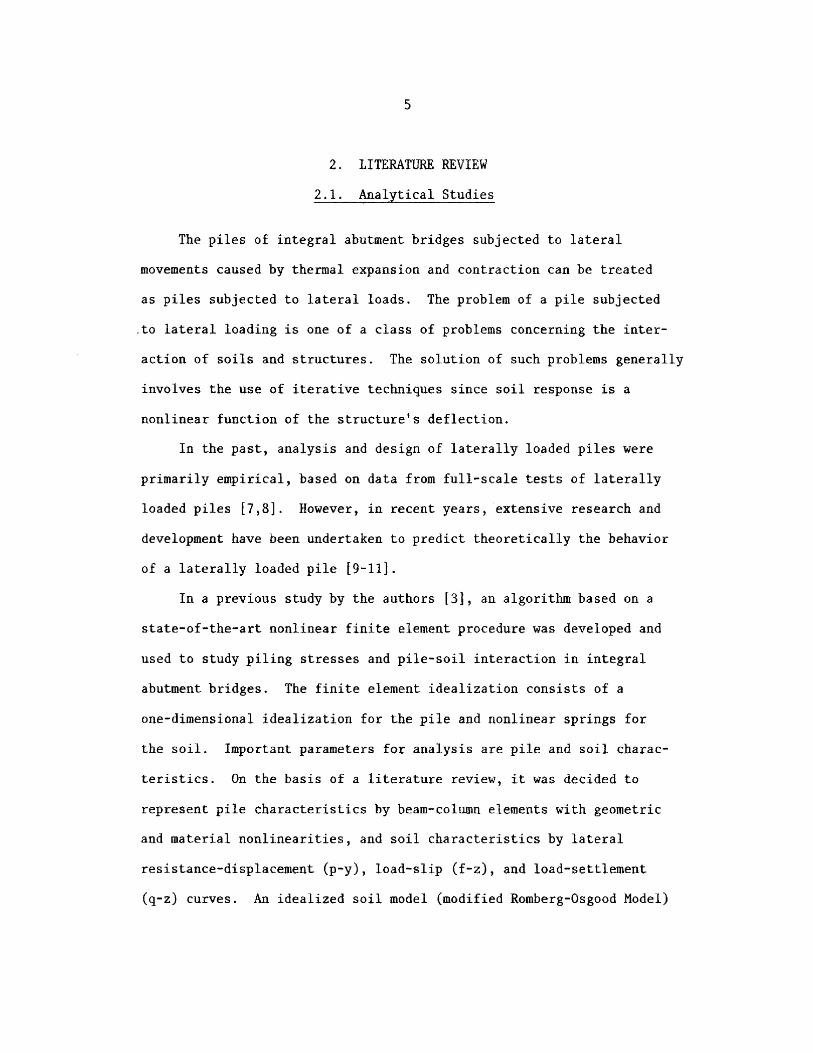
expansion and contraction caused by temperature changes. Figure 2
shows the elevation and part plane view of the test specimen.
The main objective of this investigation was to study and evaluate
the effects of thermal movements on integral abutment bridges during
early and final construction stages. Particular emphasis was placed
on evaluation of the resultant state of stress for the upper portion
of the steel piling and portions of the girders immediately adjoining
the integral abutment.
The details of specimen instrumentation and the arrangement of
data acquisition are given in the report [1]. In order to simulate,
within practical limits, possible extreme field temperature conditions
and variations, two main test cycles were used for all stages, namely
an expansion cycle and a contraction cycle. In both cycles the rate
of applied movements at the jacking end of the girders relative to the
fixed jacking abutment was established at 0.250 inch per hour. The
maximum predetermined longitudinal movements were in the range of
±1.000 inch. The movements used in this study may be applied to an
infinite number of span length combinations and initial temperature
starting points.
The following results have been obtained from the observed data
of this study:
1. Stage I: High stresses were not apparent on any part of the
test specimen. The induced bending moment, however, was very
small and produced only negligible flexural stresses in the
girder. The flexural stresses in the steel piling were much
more pronounced than the flexural stresses in the girder
. ~ c::i c:(
al c::c _J V)
-N ..........
l ~ BRG.
--- -,-1 I'
: \. I
a::: I
£ JACKING ABUT.
ll) ,_,(-l \...1 _,_)
~~-;. .. ;.-;-------------(..,;).! ~----------·-------:pw-...L 1 rIJ I E_") (T~ I-~----------------· -------------------L '+
I t; I I I , Ul 1<1) Ol1) ......
Ji ....... HALF PLAN
O(I>
25 I - 0 11 SPAN
i;:~T·:-·:·:~ ... :?~;.::: .· ~<:· ::>~ ;" ...... :: ·.;. ··!f ·~y:,.--:~·,;:·T-f-:.~-= :~,.·=:;;;~:~;-;~:::.~~:-:. :::~:--.a;~:;:~:·Ji~-:·~::~--::::~Ji
FOR STAGES I &
~1~-i -N
I -....,
r-r--
IE .. :. ;\.1§1=~ ·'.'· :: ""- - ........... :i:a.-... :.. ·'·--·--' -1>'>.otN a
I (· .. ;.~ ~ /
<EATED TIMBER , .• nt••• ,•-. -1'-i·1r····~--~-·~·J~·-~·~~£1 • ···--\·: 21:·___i_N
p I LI NIG __ .., • ._, ~•1-----">1..._-1-1 -•._11--11~M
JACKING ABUTMENT
SECTION A-A
Fig. 2. General drawing of test model.
I-
C:

11
because of small section modulus about the weak axis of the
pile. The maximum piling stresses were much less than the
yielding stress of the steel pile.
2. Stage II: A much larger induced bending moment was observed
in the girder near the integral abutment, and the induced
flexural stresses by this moment were no longer negligible.
The stresses in the steel piling were so large that definite
yielding at the edges of the pile flange was observed. It
was also noted that the recorded largest stress was only
three inches below the bottom of the concrete abutment.
3. Stage III: The addition of a concrete deck slab with the
girder and the integral abutment greatly reduced the rotation
of the integral abutment. This result is attributable to the
greater rigidity resulting from the composite action of the
girder and the deck slab. The piling stresses were also
larger than those of Stage II, and yielding was indicated at
the edges of the steel pile flanges. Because of the increased
rigidity, the induced bending moment in the girder was sizable
and would have to be taken into account if the true girder
stress was desired.
4. Stage IV: The structural response of the test specimen
depends heavily upon the physical conditions of the backfill.
As indicated by the test results, the stresses at various
parts of the test specimen in this stage were of greater
magnitude during the expansion cycle than during the contrac
tion cycle. This result is attributed to the passive soil
12
resistance of the backfill to expansion, and to the fact that
active soil pressure actually helps contraction. The induced
bending moments and end shears were appreciable and could no
longer be ignored; the flanges of the steel piling were
yielding; and composite actions between the concrete slab and
the steel girder did occur as indicated by the girder stresses.
The following conclusions were made from the test results. It
can be seen that pile yielding would occur for a one-inch movement in
all stages except Stage I. It is known that full plastic moment can
be developed in the pile about its weak axis if the axial stress does
not exceed 40% of the yielding stress. Stability of the pile and
design safety factor must be considered at this point. A conservative
1/2-inch allowable lateral movement is required in integral abutment
steel bridges to avoid pile yielding. The frozen and unfrozen condition
of the backfill will cause a totally different stress resultant to
develop in the girder. This problem, however, even if it cannot be
eliminated, can at least be minimized by providing a proper drainage
system in the backfill.
Special attention must be paid to the selection of an approach
slab system. Out of many possible choices, the most favorable is the
one which has little or no restriction to rotation or translation of
the integral abutment and does not tend to compact the backfill material
as a result of moving traffic loads. Compaction of the backfill by
moving traffic increases earth resistance to expansion movement of the
integral abutment and results in higher stresses in the girder [1].
13
2.2.2. North Dakota Tests
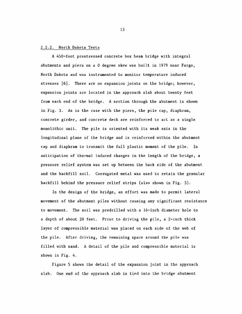
A 450-foot prestressed concrete box beam bridge with integral
abutments and piers on a 0 degree skew was built in 1979 near Fargo,
North Dakota and was instrumented to monitor temperature induced
stresses {6]. There are no expansion joints on the bridge; however,
expansion joints are located in the approach slab about twenty feet
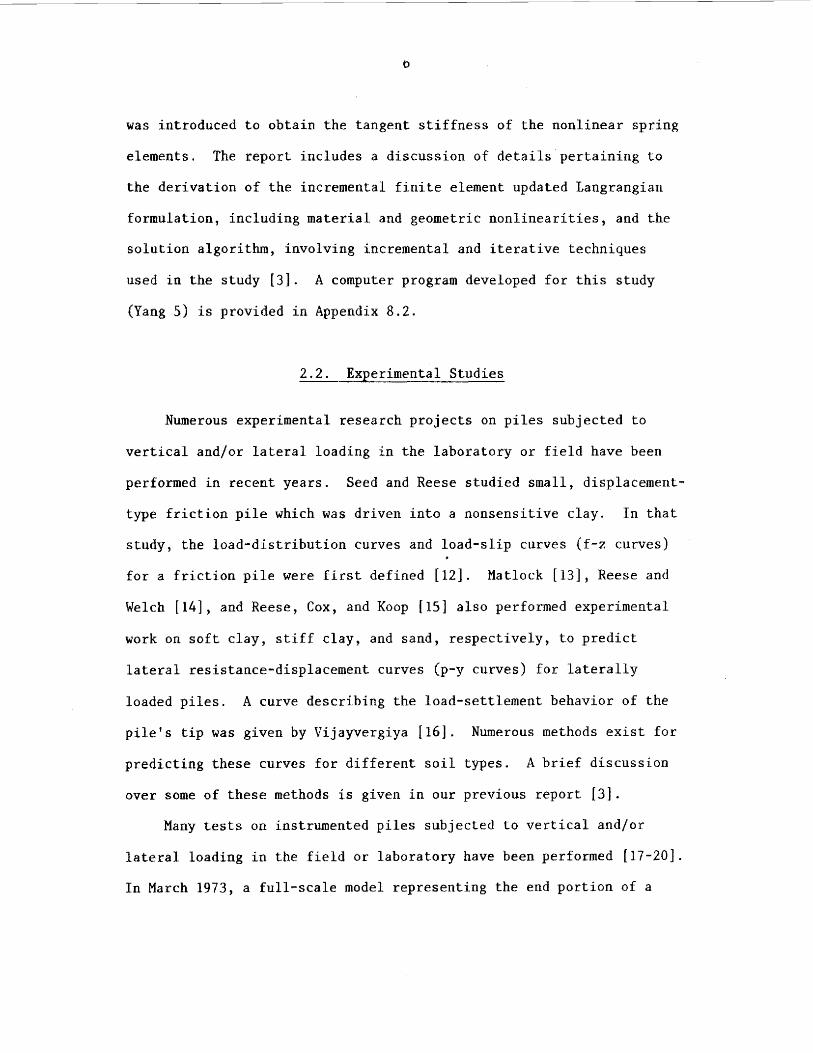
from each end of the bridge. A section through the abutment is shown
in Fig. 3. As is the case with the piers, the pile cap, diaphram,
concrete girder, and concrete deck are reinforced to act as a single
monolithic unit. The pile is oriented with its weak axis in the
longitudinal plane of the bridge and is reinforced within the abutment
cap and diaphram to transmit the full plastic moment of the pile. In
anticipation of thermal induced changes in the length of the bridge, a
pressure relief system was set up between the back side of the abutment
and the backfill soil. Corrugated metal was used to retain the granular
backfill behind the pressure relief strips (also shown in Fig. 3).
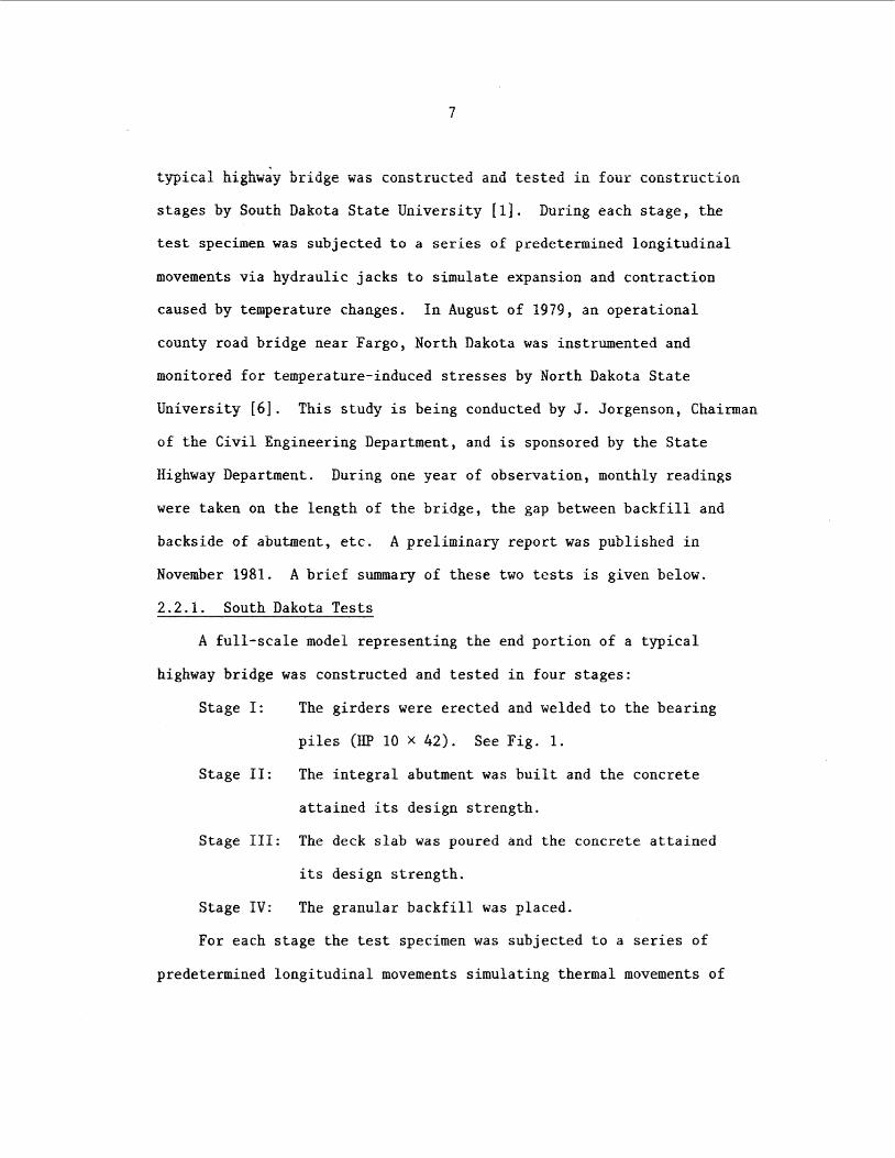
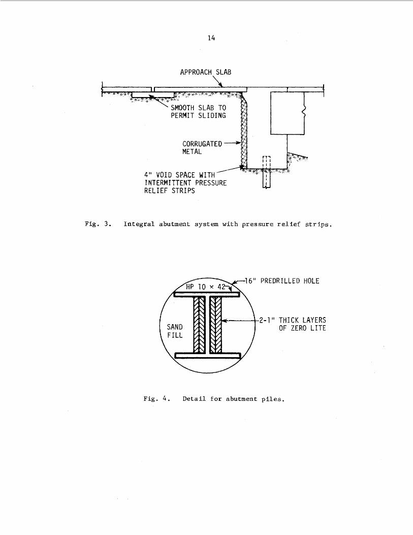
In the design of the bridge, an effort was made to permit lateral
movement of the abutment piles without causing any significant resistance
to movement. The soil was predrilled with a 16-inch diameter hole to
a depth of about 20 feet. Prior to driving the pile, a 2-inch thick
layer of compressible material was placed on each side of the web of
the pile. After driving, the remaining space around the pile was
filled with sand. A detail of the pile and compressible material is
shown in Fig. 4.
Figure 5 shows the detail of the expansion joint in the approach
slab. One end of the approach slab is tied into the bridge abutment
14
APPROACH SLAB
SMOOTH SLAB TO PERMIT SU DING
411 VOID SPACE WITH INTERMITTENT PRESSURE RELIEF STRIPS
Fig. 3. Integral abutment system with pressure relief strips.
16 11 PREDRILLED HOLE
~---+-2-1 11 THICK LAYERS OF ZERO LITE
Fig. 4. Detail for abutment piles.
15
with the other end set on the smooth surface of a supporting slab. As
the bridge changes in length, the expansion joint will open and close.
Bridge measurements were taken during the period from August 8,
1979 through September 7, 1980. The bridge measurements included
(1) change in bridge length, (2) movements between abutments and soil
backfill, (3} vertical movement of abutments and piers, (4) displacement
of abutment piles, (5) measurement of stresses in piles, and (6) measure
ment of concrete temperature. Stable readings were observed in the
laboratory check of gages and again in the fall after the abutment was
poured. During the following spring the area was flooded to a level
above all of the strain gages. Following the flood the readings for
most gages would not stabilize. Due to these erratic readings, measure
ment of stresses in the piles could not be obtained from the electrical
resistance gage data. An alternative way to estimate the pile stresses
was based on pile and abutment displacement.
After an analysis of the data obtained for a one year period of
observation, the following conclusions were made:
•
•
The maximum change in the bridge's length resulting from
thermal change can be calculated by using a temperature change
equal to ~T = r 1 - T2 + (T3 - T1)/3 where
Tl = at dawn air temperature on the hottest day.
T2 = at dawn air temperature on the coldest day.
T3 = maximum air temperature on the hottest day.
The above change in bridge length agrees well with changes in
length measured by tape measurement and measurements of openings
in expansion joints.

J.V
SMOOTH SLAB TO PERMIT SLIDING
1 1/2" @ 60°F
Fig. 5. Expansion joint in approach slab.
17
• The change in bridge length did not result in equal movement
at the two ends of the bridge. At the point of maximwn bridge
shortening, the south abutment moved in 1.96 inches and the
north abutment moved in 0.76 inches from their initial August
positions.
• In one year the gap between the abutment and backfill closed
about one-half inch on the north abutment and three-fourths of
an inch on the south abutment.
• The vertical movements of the abutment and piers were nearly
zero.
• The method of measuring pile stresses failed; however, an
analytical model was developed to predict stresses in the
piles caused by movements of the abutments.
The model developed to predict piling stresses caused by abutment
movement in this investigation (North Dakota research) is similar to
the model used in the previous report (Iowa State research). The main
difference between the two models is that the one used by Iowa State
researchers assumes nonlinear soil behavior while the one used by
North Dakota researchers assumes linear soil behavior [6].
19
3. SURVEY OF CURRENT PRACTICE FOR SKEWED BRIDGES WITH INTEGRAL ABUTMENTS
As background for a theoretical investigation to establish tenta-
tive recommendations on maximum safe lengths and skew angles for
concrete and steel skewed bridges with integral abutments, a survey of
the different states was made to obtain information on the design and
performance of integral abutment skewed bridges. This chapter summarizes
the findings of the survey including
• Various design criteria and limitations used.
• Typical pile orientations used in bridge design by the different
states, and types of analysis used for thermal expansion and
contraction.
• Assumptions made regarding selected design parameters.
• Specific construction details used such as approach slab, back-
fill, and pile cap.
• Long-term performance of skewed bridges with integral abutments.
3.1. Method of Investigation
Surveys concerning the use of integral abutments have previously
been conducted [3,6]. Responses indicate that most highway department
agencjes establish their own limitations and criteria in designing
integral abutments. The bases of these limitations and criteria are
primarily empirical.
Today, the use of integral abutments in design has been accepted
by 28 state highway departments and the Direct Construction Office,
20
Region 15, Federal Highway Administration [3]. A survey questionnaire
was prepared in cooperation with the Office of Bridge Design, Highway
Division, Iowa Department of Transportation (DOT) to obtain information
concerning the use and design of skewed bridges with integral abutments.
A copy of the questionnaire is shown in Appendix 8.1.
The survey questions were directed at pile orientations in the
integral abutments. The states were asked to state what structural
assumptions were being made in determining fixity conditions on pile
head and directions of thermal expansion and contraction of the integral
abutments of skewed bridges. In addition, questions included the
treatments of approach slab, backfill, and pile cap. Sketches of
different types of pile orientations in integral abutments were also
included in the questionnaire.
3.2. Trends of Response
Of the 28 responses received, 26 indicated the use of integral-type
abutments on skewed bridges. Among these states, Virginia has design~~
its first integral abutment skewed bridge with a small skew (10°) and
a relatively small anticipated movement at each abutment (± 3/8n).
The states of Connecticut and Oklahoma indicated that they do not use
integral abutments on skewed bridges. While Connecticut has not
constructed any integral abutments on a skew, it has constructed one
non-skewed integral abutment bridge. Oklahoma, in contrast, considered
integral abutments on skews inappropriate because of integral
displacement.
21
One of the purposes of this study is to present methods of analysis
and design details of integral abutments on skewed bridges. Many of
the states using integral abutments on skewed bridges provide useful
empirical experience to shed some light on this problem.
Summary of Responses
Following is a discussion, keyed to survey question numbers, of
the responses received from states using integral abutments on skewed
bridges. (Also see Appendix 8.1.)
Question No. 1. The pile orientations in the integral abutments
on skewed bridges shown in the first survey question can be classified
into two parts: (1) the web of the pile perpendicular or parallel to
roadway center line, e.g., Type (la) and (lb), respectively; (2) the
web of the pile parallel and perpendicular to center line of the
abutment, e.g., Type (2a) and (2b), respectively. The responses
indicated that six states use Type (la) orientation, one state uses
Type (lb), ten states use Type (2a), and fifteen states use Type (2b).
In addition, three states use circular piles, Type (3), in integral
abutment on skewed bridges.
One major difference between skewed and non-skewed integral abut
ment bridges is that when both are subjected to thermal expansion and
contraction, the former will experience thermal-induced biaxial bending
stresses on piles if the pile orientation specified is of Type (2a) or
(2b). This becomes a 3-D analysis problem. For Types (la), (lb), and
(3), pile orientations will have the same thermal effects as those for
non-skewed integral abutment bridges [3]. The responses showed that
zz
15 of 26 states have adopted the pile orientations so that bending
will be primarily about the strong axis.
A second questionnaire was sent out to investigate whether any
theoretical, experimental, or empirical bases exist for the orienta
tion of the piles and to find out if any distresses or problems asso
ciated with orientation of the piles have occurred. The responses
received from the second questionnaire indicated that most states do
not have any clear theoretical, experimental, or empirical bases.
Idaho officials assumed some creep in the soils surrounding the piles
and also assumed that a redistribution of stresses will occur since
thermal forces are generally applied gradually. Also, the restraint
provided by the integral abutment was assumed to reduce the magnitude
of the thermal movement; orienting the piles with the strong axis
parallel to the center line of the bearings was assumed to give more
rigidity for earthquake loads when liquification of embankment is
anticipated. Vermont oriented the piles to resist the force of earth
pressure from the abutment backfill rather than the force of thermal
expansion. California explained its policy of orienting the web of
piles perpendicular to the center line of the abutment (see Appendix
8.1) as follows: for a square bridge, such orientation of piles
results in bending about the strong axis of the piles because of both
thermal forces and active soil pressure. When the bridge is skewed,
however, temperature forces act along the center line of the roadway,
not parallel to the pile web, and active soil pressure acts against
the strong axis of the pile. A particular concern is rotational
action caused by the active soil pressure on skewed bridges. Temperature

23
effects are somewhat compensated for by predrilling for driven piles
and filling the voids with pea gravel or sand [21].
Colorado replied that they were unaware of any distress in the
piling. In a few cases, with cast-in-place post-tensioned bridges
with integral abutments, cracks have been detected in the abutment
wall at the intersection of the superstructure and the abutment. The
state suspected that the cracks resulted primarily from movements of
the superstructure caused by elastic shortening and creep from the
post-tensioning forces. North Dakota has been building bridges for
about 18 years using this method and so far is unaware of any problems.
According to Iowa bridge engineer H. Gee [2], pile orientation Type
(la) is not considered in design because of construction work difficulty
in arranging the reinforcement in the integral abutments. Thermal
induced biaxial bending stresses on piles can be avoided by using
Type (3) circular pipe piles. The major disadvantages are that the
vertical bearing capacities of these piles are usually less than those
of the steel H piles, and they are stiffer than H piles about the weak
axis.
Question No. 2. The second survey question revealed the following.
(1): Two states indicated that a roller assumption was made at the
pile top; eight reported a pinned assumption; one assumed partial
fixity; and eight states assumed a totally fixed pile top. These
assumptions were actually based on the restraint conditions on the
pile top. In Iowa, the pile top is completely restrained by spiral
reinforcement in the pile cap, and total fixity is assumed . For a
pinned ass~ption, the top portion of piling is enclosed with a flexible
24
material before casting in the concrete abutment [2]. (2) and (3): Only
a few states consider thermal, shrinking and soil pressure forces when
calculating pile loads. For a long integral abutment skewed bridge,
temperature-induced stresses become very critical to the piling load
capacities. If pile orientations (2a) and (2b) are adopted, the
thermal expansion or contraction along the roadway.center can be
divided into two components, one parallel to pile web (transverse),
the other perpendicular to pile web (longitudinal). Thus, the piles
in integral abutment skewed bridges will be subjected to biaxial
bending resulting from thermal movement. It is also possible that in
the diagonal direction of long skewed bridges, diagonal thermal expansion
and contraction will cause serious problems. However, none of the
states indicated concern about this. Following are some of the remarks
made regarding thermal effects on integral abutments on skewed bridges:
• Assume that the pile is fixed a certain depth below the bottom
of the pile cap and any thermal movement is accomplished by
bending in the pile.
• Thermal expansion parallel to the pile cap can be resisted by
the friction force between the backfill and the end wall.
• The batter selected piles are adopted in the integral abutments
to resist thermal movement.
e Shear keys are used on the bottom of the pile cap to prevent
lateral movement of the pile cap on extreme skews (40° ±).
• If the bridge design has a small skew (< 10°) and a relatively
small anticipated movement at each abutment (± 3/8"), no
25
special consideration need be given beyond that of a 0° skew
condition.
Question No.3. Most states indicated that a free-draining granular
material is used as backfill behind the abutment. One state uses
1-1/2 feet of porous backfill from subgrade to the bottom of the
integral abutment along with 6-inch diameter pipe underdrain. Beyond
that, normal job site_ available material is used. Some responses,
however, indicated that backfill compaction has always been something
of a problem with settlement just off the end of the bridge. Otherwise,
no special treatment has been used. Several states indicated that
rigid pile cap has been used, and pile was cast into a pile cap 1 to 2
feet long. Two states indicated that the pile cap is designed as a
reinforced continuous beam over the piling.
The survey responses show, in general, that the approach slab can
be tied to the abutment with dowels and moved back and forth with the
superstructure if a construction joint is provided between the approach
slab and the bridge slab. South Dakota stated that at least one
approach slab panel with curb and gutter section attached to the
bridge end is necessary to prevent erosion of the shoulder behind the
abutment wing. One state pointed out that while an expansion joint is
specified between rigid pavement and the approach slab, no special
treatment is specified for flexible pavement. In Colorado, the approach
slab was used if the bridge length was over 200 feet.
Question No. 4 Following are some additional comments on skewed
bridges with integral abutments:
LO
• Some of the piles in the abutment have to be battered to resist
the active earth pressure acting behind the abutment.
• Rotational forces from the lateral earth pressure on the end
walls cause a failure of the pier anchor bolts on the exterior
girders.
• For a cast-in-place bridge, the ends of steel beams may be
cast into the abutment concrete, reinforcing to the extent
that they are considered essentially integral.
• Piles may be prebored for a distance of 5 to 20 feet below the
bottom of the pile cap.
• Since the piles are oriented to allow bending about the weak
axis, any stresses caused by rotation will only stress the
outmost flange fibers and not the web and center portions of
the flanges. When the abutment is skewed, some twisting may
be induced in the p1les when the structure deflects, but this
problem can be considered negligible.
A comprehensive summary of the responses by the different states
is given in Appendix 8.1, in which N and Y represent no and yes responses,
respectively.
3.3. Summary and Conclusions
Previous research work in the area of integral abutments includes
surveys of detailing and design criteria used by the state highway
agencies, full-scale model tests, and monitoring of performance at
actual bridge installations. The present survey responses indicated
27
that 26 states use integral-type abutments on skewed bridges. Most
states design integral abutments on skewed bridges on the basis of
empirical experience, and no theoretical analysis is introduced in
design.
For integral abutments on skewed bridges, 15 states orient their
piles with the web of the piles perpendicular to center line of the
abutment [Type (2b)] so that bending will be primarily about the
strong axis. Thus, thermally-induced biaxial bending stresses will be
introduced into the piles. But the survey responses show that most
states ignore the thermally-induced bending stress caused by transverse
thermal movement. Kansas indicated that transverse thermal movement
can be eliminated by using shear keys on the bottom of the pile cap.
The major reasons given for using Type (2b) pile orientation are
• The restraint provided by the integral abutment reduces the
magnitude of the thermal movement. Orienting the pile with
the strong axis parallel to the center line of the bearings
gives more rigidity for earthquake loads when liquification of
embankment is anticipated.
• Thermal expansion is actually very small, and the backfill
material around the abutment and piling seems to yield suffi
ciently so that no distress is apparent. The piling is oriented
to resist the force of earth pressure from the abutment backfill
rather than the force of thermal expansion.
• Temperature forces act along the center line of the roadway,
not parallel to the pile web, and active soil pressure acts
against the strong axis of the pile. Temperature effects are
28
partially compensated for by predrilling for driven piles and
filling the voids with pea gravel or sand.
Usually no special treatments are given to backfill and pile cap
on skewed bridges, and they might be constructed as they are for
non-skewed bridges. As for the approach slab, it may be tied to the
abutment with dowels, or an expansion joint may be provided between
the approach slab and the bridge slab. Some states put an expansion
joint a certain distance behind the approach slab. In this case, the
approach slab will act integrally with the abutment.
It has been over 15 years since the first integral abutments on
skewed bridges were constructed. No serious problems or distresses
have been discovered as yet. Given the lack of theoretical and experi
mental research in this area, it is hoped that this survey will provide
some useful empirical experience and information on the design of
skewed bridges with integral abutments.
29
4. INFLUENCE OF DIFFERENT FACTORS ON BEHAVIOR OF INTEGRAL ABUTMENT BRIDGES
4.1. Integral Abutment Idealization
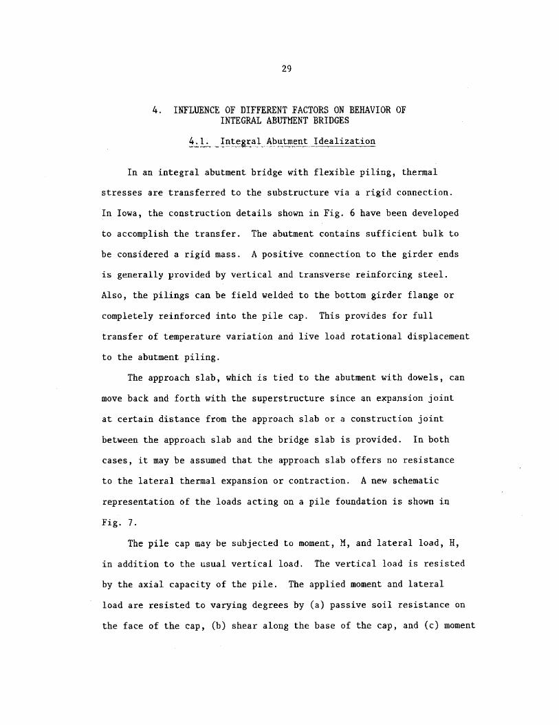
In an integral abutment bridge with flexible piling, thermal
stresses are transferred to the substructure via a rigid connection.
In Iowa, the construction details shown in Fig. 6 have been developed
to accomplish the transfer. The abutment contains sufficient bulk to
be considered a rigid mass. A positive connection to the girder ends
is generally provided by vertical and transverse reinforcing steel.
Also, the pilings can be field welded to the bottom girder flange or
completely reinforced into the pile cap. This provides for full
transfer of temperature variation and live load rotational displacement
to the abutment piling.
The approach slab, which is tied to the abutment with dowels, can
move back and forth with the superstructure since an expansion joint
at certain distance from the approach slab or a construction joint
between the approach slab and the bridge slab is provided. In both
cases, it may be assumed that the approach slab offers no resistance
to the lateral thermal expansion or contraction. A new schematic
representation of the loads acting on a pile foundation is shown in
Fig. 7.
The pile cap may be subjected to moment, M, and lateral load, H,
in addition to the usual vertical load. The vertical load is resisted
by the axial capacity of the pile. The applied moment and lateral
load are resisted to varying degrees by (a) passive soil resistance on
the face of the cap, (b) shear along the base of the cap, and (c) moment
Fig. 6.
Fig. 7.
<t_ ABUTMENT BEARING
30
PORTION OF BEAM ENCASED IN ABUTMENT
BRIDGE BEAM
Typical integral abutment used by Iowa DOT.
PILE CAP
v
~L·'"\WM/%\Y/J\'
A schematic representation of loads acting on a pile foundation.
31
and shear resistance of the pile at the junction to the cap. Clearly,
the moment and shear resistance of the piles are functions of the
strength and stiffness of both soil and pile.
Passive soil resistance can be very effective in resisting lateral
loads, but consideration must be given to the fact that it may not be
permanent. Repairs, alterations, or other projects may be cause for
removal of the soil; therefore, passive soil resistance is usually
discounted or ignored. Shear along the base of the cap also can be
very effective in resisting lateral loads. However, a slight settlement
of the soil beneath the cap can essentially eliminate this resistance,
and it is usually ignored for design purposes. The moment and shear
resistance of the pile is usually the major factor considered sufficiently
permanent for use in design. According to Iowa bridge engineers, it
would be more conservative in design to ignore the passive soil and
shear resistance of the cap [2]. The loads transferred from the
abutment to the pile are shown in Fig. 8.
4.2. Influence of Rotation at the Pile Head
The piling top embedded in the concrete abutment footing (pile
cap) can be assumed to be (a) fully restrained without rotation,
(b) partially restrained, allowing some degree of rotation, or (c) pinned,
allowing rotation but not translation. For a small lateral displacement
of superstructure, such conditions as (b) and (c) can be achieved to a
large degree at the top of the piling by enclosing the top portion of
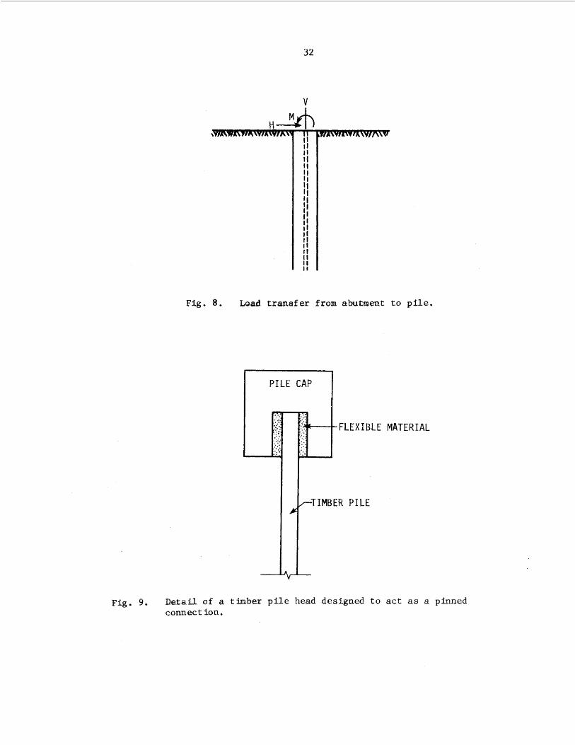
Fig. 9.
32
Fig. 8. Load tranaf er from abutment to pile.
PILE CAP
~::_ ... : _ _,_FLEXIBLE MATERIAL .\
HMBER PILE
Detail of a timber pile head designed to act as a pinned connect ion.
33
the piling with a flexible material before being cast in the concrete
abutment footing, as shown in Fig. 9.
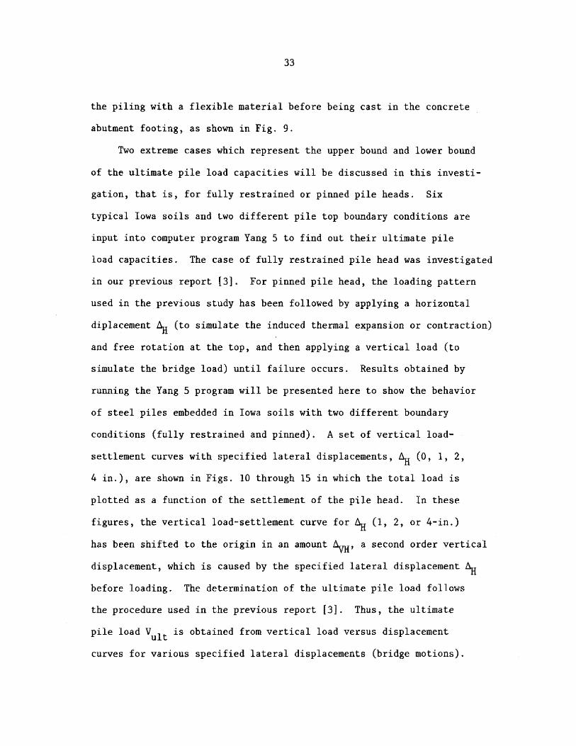
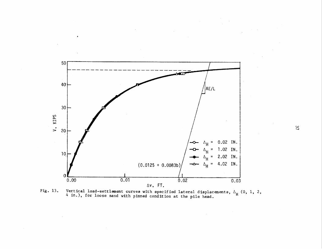
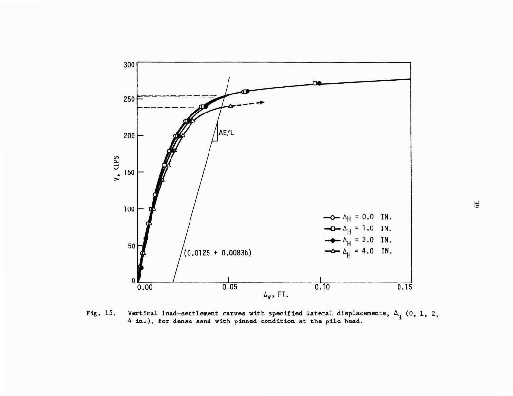
Two extreme cases which represent the upper bound and lower bound
of the ultimate pile load capacities will be discussed in this investi
gation, that is, for fully restrained or pinned pile heads. Six
typical Iowa soils and two different pile top boundary conditions are
input into computer program Yang 5 to find out their ultimate pile
load capacities. The case of fully restrained pile head was investigated
in our previous report [3]. For pinned pile head, the loading pattern
used in the previous study has been followed by applying a horizontal
diplacement ~ (to simulate the induced thermal expansion or contraction)
and free rotation at the top, and then applying a vertical load (to
simulate the bridge load) until failure occurs. Results obtained by
running the Yang 5 program will be presented here to show the behavior
of steel piles embedded in Iowa soils with two different boundary
conditions (fully restrained and pinned). A set of vertical load
settlement curves with specified lateral displacements, ~ (0, 1, 2,
4 in.), are shown in Figs. 10 through 15 in which the total load is
plotted as a function of the settlement of the pile head. In these
figures, the vertical load-settlement curve for ~ (1, 2, or 4-in.)
has been shifted to the origin in an amount .l\Ttt' a second order vertical
displacement, which is caused by the specified lateral displacement ~
before loading. The determination of the ultimate pile load follows
the procedure used in the previous report [3]. Thus, the ultimate
pile load Vult is obtained from vertical load versus displacement
curves for various specified lateral displacements (bridge motions).

(/) 0-....... ::.i:::
5.0
4.0
3.0
.; 2.0
, I ---------------------~ I
AE/L
-o- L1H = 0 • 0 IN •
-o-.6.H=l.OIN.
~.6.H = 2.0 IN.
~.6.H = 4.0 IN.
0.0._f ------,---~--
Fig. 10.
0.00 0.01 0.02 0.03 .6.v, FT.
Vertical load-settlement curves with specified lateral displacements, .6.H (0, 1, 2, 4 in.), for soft clay with pinned condition at the pile head.
Vo .f:'

(/)
Cl.. -~ "' >
100
80
60
40
Fig. 11.
------------------__;;;--:,_ ~
I
-o- 6H == 0.0 IN.
-0- 6H :: 1.0 IN.
(0.0125 + 0.0083b) -e- 6H == 2.0 IN.
--t::r- 6.H == 4 • 0 IN .
-0.01 0.02 0.03
lv, FT.
Vertical load-settlement curves with specified lateral displacements, 6.H ( 0,. 1, 2, 4 in.), for stiff clay with pinned condition at the pile head.
w Vt

vrt-cF 350t- - I I J-~ 7
300
250
200 V> 0... 1-4
:::r.::::
.; 1501 »I' f I I
100 t- ,, ~ I -o- tiH = 0.0 IN. --0- llH = 1 . 0 IN.
-+-llH = 2 .0 IN.
5~~/ I -6- ~H = 4.0 IN.
0--~~~-r..~~~~~~~~~"'--~~~--o.~~~~-'-~~~~-'-~~~---''--,---~~-r..~---o.oo 0.01 0.02 0.03 0.04 0.05 0.06 0.07
Fig. 12.
0.08 6v, FT.
Vertical load-settlement curves with specified lateral displacements, ~H (0, 1, 2, 4 in.), for very stiff clay with pinned condition at the pile head.
w (j'\
V'> 0.. ~
~
...
50
40
30
> 20
---------------------------:.,..,. ;' 1
6 = H 6 = H
0. O~~ IN.
1.m~ IN.
0[ 2.0,3~ IN.
0. 00 4 • 02 IN.
10 -+- 6H =
-t:r- 6H
Fig. 13.
0.01 0.02 0.03 6v, FT.
Vertical load-settlement curves with specified lateral displacements, 6H (O, 1, 2, 4 in.), for loose sand with pinned condition at the pile head.
w _,

Fig. 14.
V'> 0.... ....... ~
250
200
150
~ 100 >
--o-6H = 0.0 IN. I -o-6H = 1.0 IN.
50 -----b.H = 2.0 IN. -b-b,
H = 4.0 IN. (0.0125 + 0.0083b)
0--~~~~~~~-..i.~~~~~~~~-'-~~~~~~~~--' 'o.oo o.o5 0.10 0.1 s
b.v' FT.
Vertical load-settlement curves with specified lateral displacements, li.H (0, 1, 2, 4 in.), for medium sand with pinned condition at the pile head.
w 00
V) a.. -
300
250
200
~ 150 .. >
lOOr ~ I I
~ 6H = 0 . 0 IN.
-o- 6H = 1.0 IN. __.., 6H = 2. 0 IN .
501-1 I ~ 6H = 4.0 IN.
0 9 I I I f
0. 00 0. 05 0. l 0 0. 15 6v, FT.
Fig. 15 . Vertical load-settlement curves with specified lateral displacements, 6H (0, 1, 2. 4 in.), for dense sand with pinned condition at the pile head.
w
"°
40
A set of curves showing ultimate pile load (Vult) versus specified
lateral displacements, ~' for different Iowa soils is shown in Figs. 16
and 17 . Nondimensional forms are given in Fig. 18 .
From the previous report [3], failure .mechanisms are generally of
two types: (a) lateral type failure, and (b) vertical type failure .
In the case of fully restrained piles, most of the analyzed pile
failures are of the second type (vertical type failure) . That is, the
applied load reached the ultimate soil frictional resistance (for
sands, soft clay and stiff clay) . For the soils in very stiff clay,
lateral failure occurs before vertical failure. In these cases a
plastic hinge which forms in the pile significantly increases the
number of iterations required for convergence . In this study, the
last converged solution was taken as the ultimate load . A set of
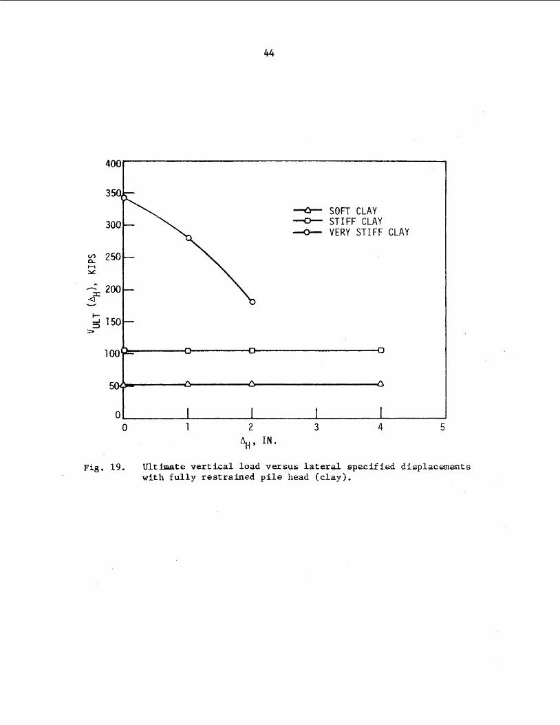
curves showing ultimate vertical load (Vult) versus specified lateral
displacements, ~, for different Iowa soils is shown in Figs. 19 and
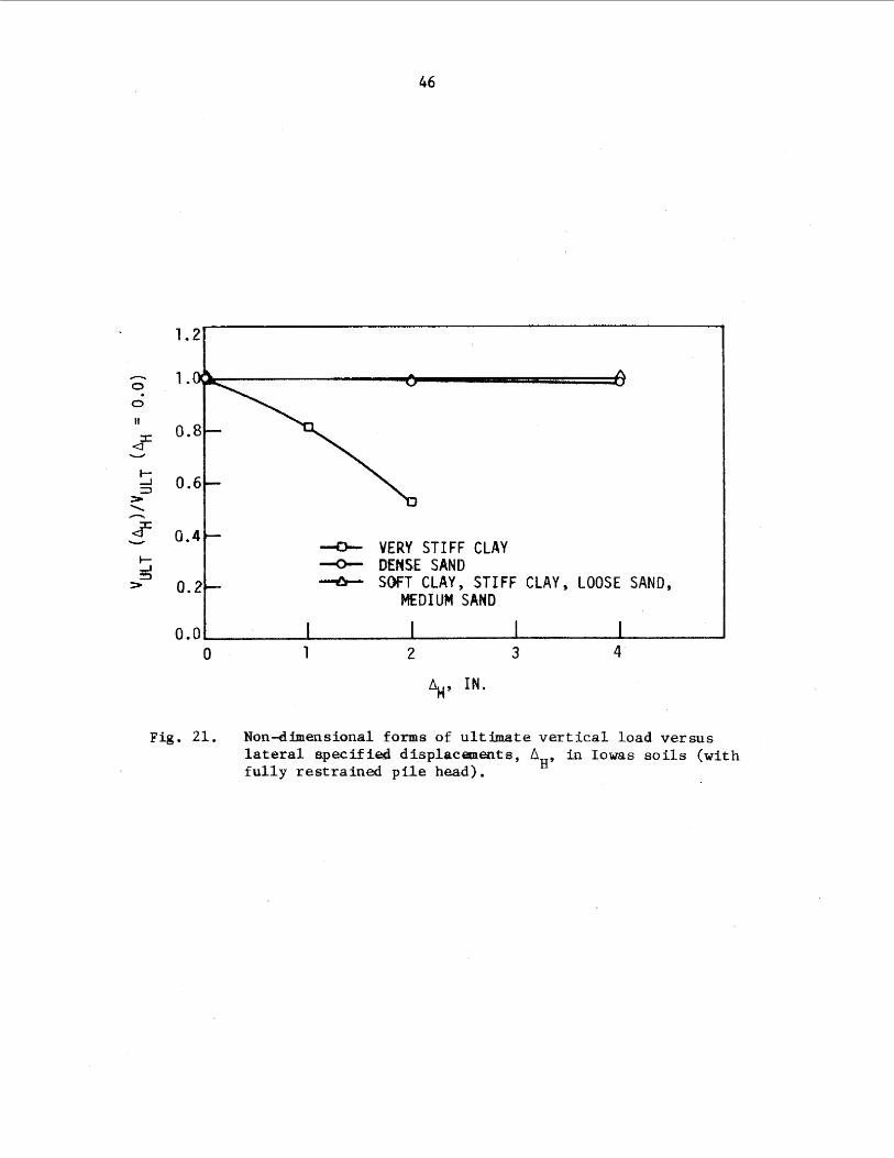
20. Nondimensional forms are given in Fig. 21.
If the pile head is allowed to rotate after a specified lateral
displacement is reached for sands, soft clay and stiff clay, there is
no significant difference . The results were similar to those of the
fully restrained pile, and the vertical type failure happened in both
the fully restrained and pinned cases. For very stiff clay, the
applied load was terminated at V = 290 kips for both ~ = 2.0 in. and
~ = 4.0 in. under pinned conditions, and at V = 180 kips for ~
= 2.0 in . in the fully restrained condition. These two cases show a
significant difference in ultimate vertical load carrying capacity
because the plastic hinge forms early in the fully restrained pile as
V') 0.. -~
.--:i::
<J -+.J ,.... ::I
>
Fig. 16.
400
350
300
250
200
150
100
50
0 0.0 1.0
41
........_ SOFT CLAY -o- STIFF CLAY ~ VERY STIFF CLAY
2.0
~H' IN.
3.0 4.0
Ultimate vertical load versus specified lateral displacements in clay with pinned condition at the pile head.
400
350~ ~ LOOSE SAND
-o- MEDIUM SAND
300 -o- DENSE SAND
250 V'l ..,. 0... --0 ...... ~
....:: 200 ~ :c
5 150t I ~ N
<J 0 0
100
5:r : : I : 0.0 LO 2.0 3.0 4.0 5.0
6H, IN.
Fig. 17. Ultimate vertical load versus specified lateral displacements in sand with pinned condition at the pile head.
L
0 .a-0 . 0
~B 0.6
<l :c __, <I .., .., .-- .-- 0.4 :::::J :::::J
> >
0.2
0.0 0.0 1.0 2.0
~ VERY STIFF CLAY -o- DENSE SAND -6- SOFT CLAY, STIFF CLAY,
LOOSE SAND, MEDIUM SAND
3.0 4.0
~H, IN.
5.0
Fig. 18. Non-dimensional form of ultimate vertical load versus specified lateral displacements, t.W in Iowa soils (pinned).
~ w
400
300
V1 250 0.. 1--1 ~
~ 200 <J:r.
j-
5 150 >
44
--6- SOFT CLAY --o-- STIFF CLAY -0-- VERY ST! FF CLAY
Fig. 19. Ultimate vertical load versus lateral specified displacements with fully restrained pile head (clay).
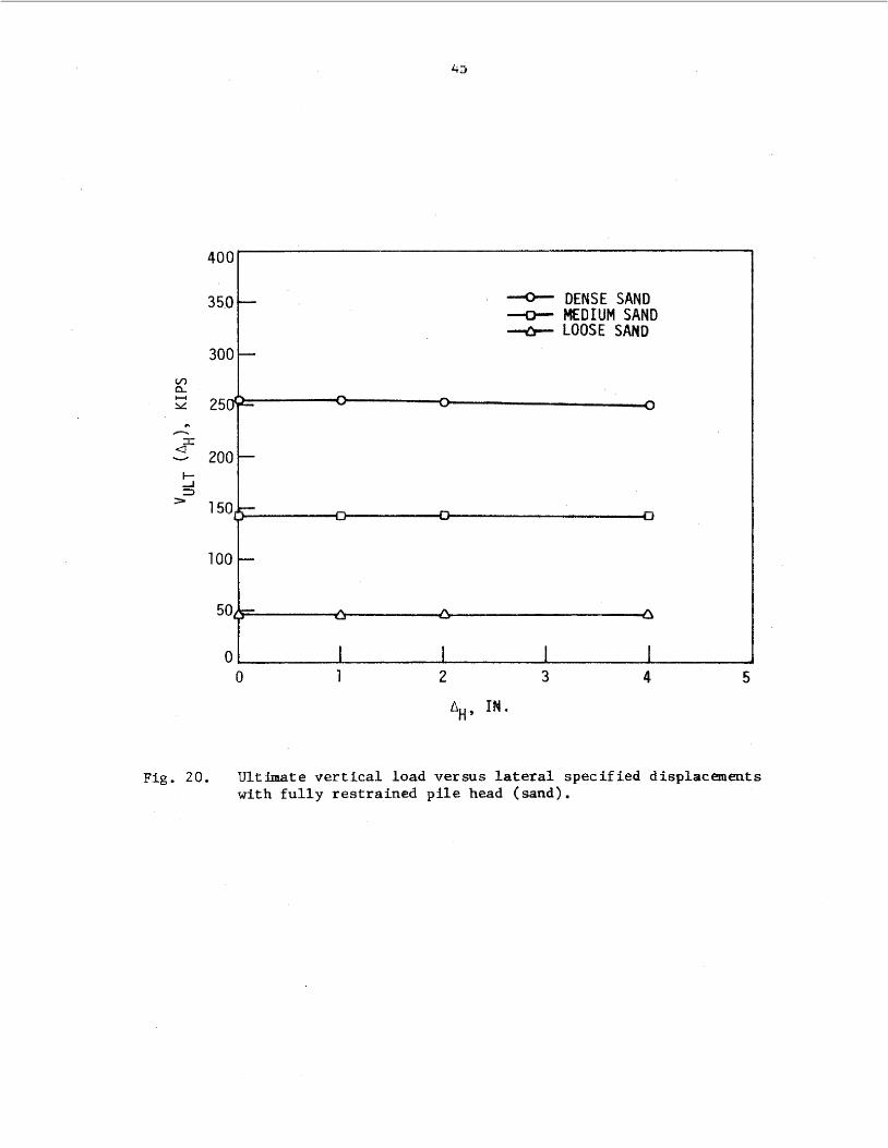
400
35.0 ---<>-- DENSE SAND -o- MEDIUM SAND --iZ-- LOOSE SANO
300 V') 0... - 25 ~
.. -:I: <l 200
......
....J =>
> 150_
100
50
0 0 2 3 4 5
Fig. 20. Ultimate vertical load versus lateral specified displacements with fully restrained pile head (sand).
0
0
II
1.2
0.4
0.2
46
--0-- VERY STIFF CLAY --0-- DENSE SAND ~ SOFT CLAY, STIFF CLAY, LOOSE SAND,
MEDIUM SAND
O.OL.-~~~~~~~~~--~~~~_,_~..._~~---~~~~__,
0 1 2 3 4
LiH, IN.
Fig. 2L Non-dimensional forms of ultimate vertical load versus lateral specified displacements, ~H' in Iowas soils (with fully restrained pile head).

47
opposed to the pinned pile. The previous report has shown that the
critical location for lateral type failure occurs in the top 10 feet
of the pile. The stresses induced by lateral movement and the applied
load are much higher in this region for fully restrained piles. Since
the pinned pile allows free rotation, the pile is more flexible to
adjust its position in order to reduce the induced stresses caused by
lateral movement.
The above discussion shows that for an integral abutment, if the
piling is cast into the pile cap and a detailed design is used to
eliminate moment constraint at the joint, the ultimate vertical load
carrying capacity of the H pile after thermal expansion or contraction
can be highly increased.
4.3. Effect of Predrilled Oversized Hole
Occasionally, during integral abutment construction, predrilled
oversized hole is considered in the following situations: (a) where
compressible soils are under a fill, the entire fill should be pre
drilled to prevent drag, (b) when steel H piles are used, the fill
should be predrilled to prevent premature bearing from the resistance
of the fill, (c) predrilled oversized hole is used to make piles that
are more flexible to sustain thermal induced movement. Piling is
driven through a predrilled oversized hole in the ground as shown in
Fig. 22. The depth of predrilled oversized holes varies from state to
state. In Iowa, all integral abutment piling of bridges with overall
length greater than 130 feet must be driven through oversized holes

48
£ ABUTMENT BRIDGE
I I
FILL THE VOID AROUND PILING WITH DRY SAND UP TO BOTTOM OF FOOTING
.,.........--PRE-DRILLED OVERSIZED HOLE
Fig. 22. A detailed design for predrilled oversized hole.
49
predrilled to a minimum of 8 feet below the bottom of the pile cap
[2]. In other states, the depth may be up to 20 feet or more. After
a pile has been driven through the predrilled oversized hole, the
voids around the pile may be filled with dry sand to prevent the
backfill from falling into the hole.
In this report the effect of predrilled oversized holes on the
ultimate pile load capacity has been investigated. According to a
previous study by the authors [3], the most critical type of soil
(very stiff clay) and its loading pattern are used in this study. The
cases studied may be classified into three categories: (a) without
pre-drilled oversized holes, (b) with predrilled oversized hole from 0
to 10 feet, (c) with predrilled oversized hole with loose sand filling
from 0 to 10 feet.
Results obtained from running the Yang 5 program will be presented
here to show the influence of predrilled oversized holes to ultimate
vertical load carrying capacity. A set of vertical load-settlement
curves with specified lateral displacement, 6ii (O, 1, 2, 4 in.), are
shown in Figs. 23 through 27 and Figs. 28 through 32 for cases (b) and
(c), respectively. A set of curves showing ultimate pile load (Vult)
versus specified lateral displacements, ~' for the very stiff clay
with predrilled oversized hole is shown in Figs. 33 and 34 for case
(b) and (c), respectively. Also, non-dimensional forms are given in
Figs. 35 and 36.
The results show that the ultimate pile load capacity is highly
influenced by the effect of predrilled oversized hole. In both cases,
cases (b) and (c), if the length of predrilled oversized hole falls in
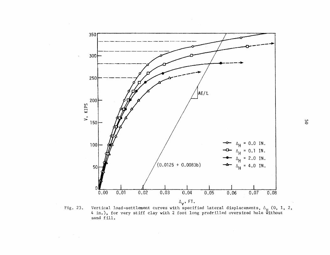
V") c.... 1-f
:::..:::
.. >
Fig. 23.
350
300 ;' . ____ _.
250
200
150~ II I I I
lOOt- <:46 I --0- 6H = 0.0 IN.
--0- liH = 0. 1 IN .
_._ liH = 2. 0 IN.
50~ j \U.UILJ • v.uuuJUJ __._ llH = 4.0 IN.
D--~~---~~--~~---~~----~~.....-~~~--~~--~~-0 .00 0.01 0.02 0.03 0.04 0.05 0.06 0.07 0.08
llv, FT. Vertical load-settlement curves with specified lateral displacements~ 6H (0, L. 2, 4 in.), for very stiff clay with 2 foot long predrilled oversized hole without: sand fill.
VI 0

350
300
250
200 V') a. ~
~ .. >
150. #Ill , I
100 I IBI / -
!!.H = 0.0 IN.
!!.H = l. 0 IN.
- !!.H = 2.0 IN. sot-• I ......_ !!.H = 4.0 IN. (0.0125 + 0.0083b)
0 .. 01 0.02 0.03 0.04 0.05 0.06
dv, FT. Fig. 24. Vertical load-settlement curves with spacifie<l lateral displacements, ~H (0, 1, 2,
4 in.), for very stiff clay with 4 foot long predrilled oversized hole without sand fill.
lJl
"'""'
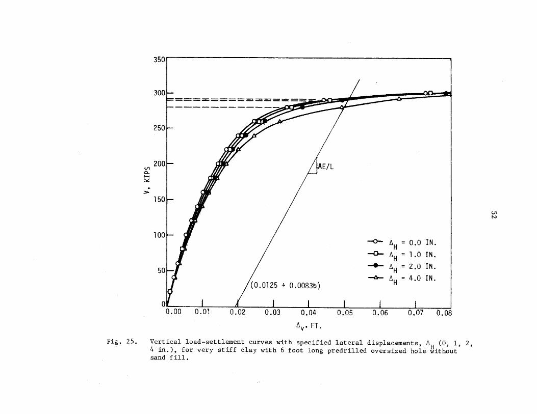
Fig. 25.
350
300
250
V> 200
0... 1-f ~
... >
150 r ~
100~ I I 50t-/ I
0.01 0.02 0.03
I
0.04
Av, FT.
0.05
I
I -o- A = 0.0 IN.
H -o- AH = 1 • 0 IN •
...._ AH = 2.0 IN.
-6-- AH = 4.0 IN.
0.06 0.07 0.08
Vertical load-settlement curves with specified lateral displacements, 6H (0, 1, 2, 4 in.), for very stiff clay with 6 foot long predrilled oversized hole without sand fill.
Vl N
VI 0.. -~
... >
Fig. 26.
3150
300
2!50
200
1 SOt- II/ I I
100 0 ~H = 0.0 IN.
0 ~H = l .0 IN.
!50 • l!.H = 2.0 IN .
A ~H = 4.0 IN.
0---~--~-----..J----~~--.,.....L-----L-----L--~ 0.00 0.01 0.02 0.03 0.04 0.05 0.06 0.07 0.08
Av, FT. Vertical load-settlement curves with specified lateral displacements, ~H (0, 1, 2, 4 in.), for very stiff clay with 8 foot long predrilled oversized hole without sand fill.
U'1 w
(/')
'l-, ....... :~ .. :>
Fig. 27 ..
350
300
250
200
150 --
100 --0- ~H = O.~ IN.
-0- ~H = 1 . 0 IN •
sot- _1 Ii,... n.'"I l'\r- • ,.... """""""'' \
-e- ~H = 2.0 IN.
~ ~H = 4.0 IN.
11' I .o ·o.oo 0 .01 0.02 0.03 0.04 0.05 0.06 0.07 0.08
i~v, FT.
Vertical load-settlement curves with specified lateral displacements, .6H (0, 1, 2, 4 in.), for very stiff clay with 10 foot long predrilled oversized hole without sand fill.
U'I ~
350 _ __...
300
-- 7• ---~
250
200 V') 0.. ...... ~ .. >
150~ u I I
-o-~H = 0 . 0 IN .
~H = 1.0 IN. 1001- df I -e-t,.H = 2.0 IN.
50
o.._~~-'-~--"""----~_.t..,,~----L------'-------L------'-------' 0.00 0.01 0.02 0.03 0.04 0.05 0.06 0.07 0.08
11v, FT. Fig. 28, Vertical load-settlement curves with specified lateral displacements, ~H (O, 1, 2,
4 in.), for very stiff clay with 2 foot long predrilled ov.ersized hole rilled with loose sand.
VI V>
350
300
250
200 V') 0.. ..... ~
~
> 150 l-- nrr I ~t,H = 0.0 IN. I
.....0-6H = 1 • 0 IN .
.......,_t,H = 2.0 IN.
1001- ~ I ~6H = 4.0 IN.
50 (0.0125 + 0.0083b)
0--~~....._~~ .......... ~~_.,~~~---~~.J.-~~-L-~~--I~~~-'---' 0.00 0.01 0.02 0.03 0.04 0.05 0.06 0.07 0.08
~v• FT. Fig. 29. Vertical load-settlement curves with specified lateral displacements, 6 (0, 1, 2,
4 in.), for very stiff clay with 4 foot long predrilled oversized hole ¥11led with loose sand.
IJl
°'
350
3001- · . ~ • :& I :;£CAP ,., L
250·-
(/) 200 ·-a.. -~
.. >
Fig. 30.
isol- 1! I -o-llH = 0.0 IN.
-o-tiH = 1.0 IN . I
....,_flH = 2 .O IN.
100 ,_ ~ I -6-llH = 4.0 IN.
50
Q,, ____________ ...._ __ ~----~----------------~----~-------0.00 0.01 0.02 0.03 0.04 0.05 0.06 0.07 0.08
tiv, FT.
Vertical load-settlement curves with specified lateral displacements, 61:1 (O, 1, 2, 4 in.), for very stiff clay with 6 foot long predrilled oversized hole filled with 1010 s e sand .
U'1 -..J
V') a.. -~ .. >
Fig. 31.
350
300
250
200
l 50r- III I -o-~H = 0.0 IN1 I --o-6H = 1.0 IN.
_._6H = 2.0 IN. 100~ db' I
_..,.~H = 4.0 IN.
50
0--~~--~~--~~----~--"'-~~-1-~~---L.~~~L-~~-'-_....I 0.00 0.01 0.02 0.03 0.04 0.05 0.06 0.07 0.08
~V' FT. Vertical load-settlement curves with specified lateral displacements, 6 (0, 1, 2, 4 in.), for very stiff clay with 8 foot long predrilled oversized hole ¥illed with loose sand.
(.,11 co
t/)
a.. ~
~
" >
Fig. 32.
350
300
250
200
I l 50r- ., I -o-6 = 0.0 IN.
H -<>-6H = 1.0 IN.
lOOJ- ad I --+- 6H = 2 • 0 IN .
--6- 6H = 4. 0 IN .
I I ~ n'hc , n nnnoLI 50
Ql_~_JL_~--d~-~--1~~_._~~---L..:-:-~-:-1:-:--~:-":":-~~;::--" 0.00 0.08 0.04 0.01 0.06 0.07 0.03 0.05 0.02
6v, FT. Vertical load-settlement curves with specified lateral displacements, 6H (0, 1, 2, 4 in.), for very stiff day with 10 foot long predrilled over sized hole filled with loose sand.
U1 ~
V> Cl.. -::it:: -:::c <l ..__..
+.> ,..._ :::::J
>
Fig .. 33.
60
350
200
150
-o- L = 2 FT. 100 -6- L = 4 FT.
-'1- L = 6 FT. __..,_ L = 8 FT.
50 -0- L = 10 FT.
al I I I 0.0 1.0 2.0 3.0 4 .. 0
~H' IN.
Ultimate vertical load versus specified lateral displacements for very stiff clay with 10 foot long predrilled oversized hole (without sand fill).

01
400
350
30
U') 250 0.. ~
:::..::::
~ 200 <1 ...._ ....,
..... :::J
>
Fig. 34.
150
100
50
0 0.0 1.0 2.0
~H' IN.
-o- L 2: 2 FT. --6- L 4 FT. ~ L 6 FT. _..., L = 8 FT. --0- L 10 FT.
3.0 4.0
Ultimate vertical load versus specified lateral displacements for very stiff clay with 10 foot long predrilled oversized hole (with loose sand).
0 . 0 -....
:I: II <I -.... :::c .µ <1 ..-:J +J
> r:J
>
Fig. 35.
62
1.2
0.6
0.4 --o- L = 2 FT. --6- L = 4 FT. -o- L = 6 FT. -.- L = 8 FT. -0- L = 10 FT.
0.2
1.0 2,0 3.0 4.0 6H, IN.
Non-dimensional forms of ultimate vertical load versus specified lateral displacements, AH' for very stiff clay with 10 foot long predrilled oversized nole (without sand fill).
0 . 0
JI ....-:J:: :J::
<] <] ..__. ..µ ..µ ....- r-:::s ~
> >
Fig. 36.
63
l.2
1.0
0.8
0.6
-0- L 2 FT. = 0.4 L 4 FT. --l!:r- =
-0- L = 6 FT. -+- L = 8 FT. 0.2 --0- L = 10 FT.
0.0 0.0 1.0 2.0 3.0 4.0
tiH, IN.
Non-dimensional forms of ultimate vertical load versus specified lateral displacements, ~H' for very stiff clay with 10 foot long predrilled oversized nole (with loose sand).
64
the range of 4 ft to 10 ft below the ground, there is no significant
reduction for ultimate load carrying capacity under specified lateral
displacements. But the major significant difference from case (a) is
that in cases (b) and (c), the ultimate load carrying capacity of the
H piles is only reduced by about 10 percent for 4 inches of specified
lateral displacement; in case (a), the ultimate load carrying capacity
of H pile is reduced 100 percent for 4 inches of specified lateral
displacement. The results obtained also indicated that the plastic
hinge forms in the top 4 ft section of the pile. If the length of
predrilled oversized hole falls in the range of 0 ft to 4 ft, the
ultimate load carrying capacity of the H piles will be reduced in case
(b) and highly reduced in case (c). The reduced ultimate load carrying
capacity of H piles for cases (a), (b), and (c) under specified lateral
displacements is summarized in Table 1.
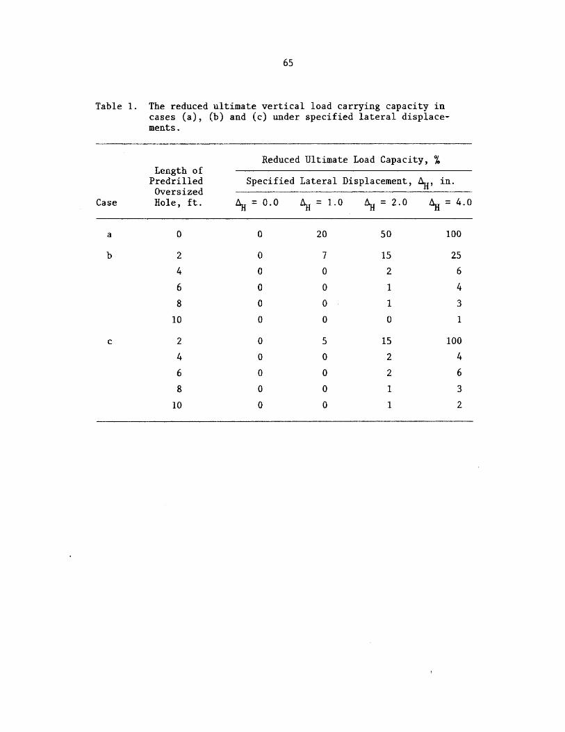
As shown in Table 1, the ultimate load carrying capacity is
highly increased in cases (b) and (c) since in both cases the piles
are more flexible than in case (a). Lateral displacements induced by
thermal expansion or contraction are easily adjusted by the flexible
pile. That is, the lateral soil stiffness in case (a) is much higher
than in cases (b) and (c), so pile stresses induced by specified
lateral displacement C11f) in case (a) are larger than in cases (b) and
(c), and they reach the yield stress, thus causing plastic hinge to
form. This explanation also applies in case (c) for 2 foot long
predrilled oversized hole with loose sand; the lateral soil stiffness
is so much greater that plastic hinge forms at ~ = 4.0 in. before
being subjected to any vertical loading.
65
Table 1. The reduced ultimate vertical load carrying capacity in cases (a), (b) and (c) under specified lateral displace-ments.
Reduced Ultimate Load Capacity, % Length of
Predrilled Specified Lateral Displacement, ~'in. Oversized
Case Hole, ft. ~ = 0.0 L\i = 1.0 ~ = 2.0 ~ = 4.0
a 0 0 20 so 100
b 2 0 7 15 25
4 0 0 2 6
6 0 0 1 4
8 0 0 1 3
10 0 0 0 1
c 2 0 5 15 100
4 0 0 2 4
6 0 0 2 6
8 0 0 1 3
10 0 0 1 2
66
The study on the effect of predrilled oversized holes assumes
zero soil resistance in the predrilled oversized holes when '1J is less
than 4 inches. In the real case, the diameter of predrilled oversized
hole in Iowa is specified as 16 inches. If the induced thermal movement
will cause pile head movement to exceed 4 inches; the soil outside the
predrilled oversized hole will resist this movement. Thus, a gap
element must be introduced into the present model because it is an
important consideration not covered in the previous model.
4.4. Layered Soils
The behavior of a loaded pile is a classic example of soil structure
interaction; the properties of the soil control the behavior of the
embedded structure. Recent experimental investigations and advances
in analytical techniques have added greatly to the general understanding
of the problem. In a previous report by the authors [3], only homogenous
soils (one layer soils) were investigated. In this study pile behavior
in non-homogenous soils (multilayer soils) is investigated.
Solutions for piles in a two-layer system have been presented by
Davisson and Gill [8]. A modulus of subgrade reaction is used to
define soil stiffness; the stiffness of the surface layer is defined
in terms of the underlying layer's stiffness. The complete range of
relative stiffness and relative thickness of the two layers is investi
gated. Davisson and Gill have shown that the surface layer exerts an
overwhelming influence on the behavior of a soil-pile system. This
conclusion agrees with the findings reported in our previous work [3]
67
which showed that the critical location where lateral type failure
forms usually occurs from ground level to 10 ft below ground.
In this investigation, soil-pile interaction has been considered
in developing the finite element model. The properties of soil and
pile elements were investigated to obtain the parameters used in the
Yang 5 Program [3]. Since the behavior of soil at a particular depth
is independent of soil behavior at all other depths [22], the soil
parameters for layered soils may be obtained with no added difficulty.
In consultation with Iowa Department of Transportation soil
engineers, several typical Iowa layered soils have been selected.
These soils and their properties are shown in Table 2. Actual soil
properties are based on laboratory or field tests. In certain situa
tions, because of geometry requirements for the lay of the land and
traffic clearance, cut and fill in road alignment are necessary.
Usually the fill is highly compacted above the ground, and the top
portion of the pile is embedded in this compacted soil [2]. The depth
of the compacted soil is specified in the range of 0 to 10 feet.
Three different cases of layered soils are discussed in this investiga
tion: (a) natural soil without compacted soil, (b) natural soil with
4 foot long compacted soil, (c) natural soil with 10 foot long compacted
soil. Based on results obtained from the previous report [3] and from
Section 4.3, the choice of the length of compacted soil can be understood.
Tables 3 and 4 show the typical Iowa layered soils in cases (a) and
(b), respectively.
A set of vertical load-settlement curves with specified lateral
displacements, ~ (0, 1, 2, 4 in.), for case (a) is shown in Figs. 37
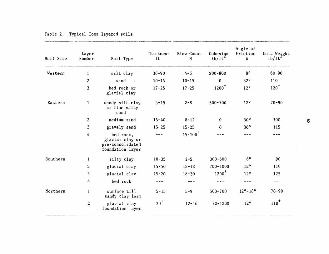
Table 2. Typical Iowa layered soils.
Angle of Layer Thickness Blow Count Cohesi~n Friction Unit We~ght
Soil Site Number Soil Type ft N lb/ft q, lb/ft
Western 1 silt clay 30-90 4-6 200-800 go 60-90
2 sand 10-15 10-15 0 32° 110+
3 bed rock or 17-25 17-25 1200+ 12° 120+ glacial clay
Eastern 1 sandy silt clay 5-15 2-8 500-700 12° 70-90 or fine salty
sand
2 medium sand 15-40 8-12 0 30° 100 °" 00
3 gravely sand 15-25 15-25 0 36° 115
4 bed rock, --- 15-100+ glacial clay or
pre-consolidated foundation layer
Southern 1 silty clay 10-35 2-5 300-600 go 90
2 glacial clay 15-50 12-18 700-1000 12° 110
3 glacial clay 15-20 18-30 1200+ 12° 125
4 bed rock
Northern 1 surface till 5-15 5-9 500-700 12°-18° 70-90 sandy clay loam
2 glacial clay 30+ 12-16 70-1200 12° 110+ foundation layer
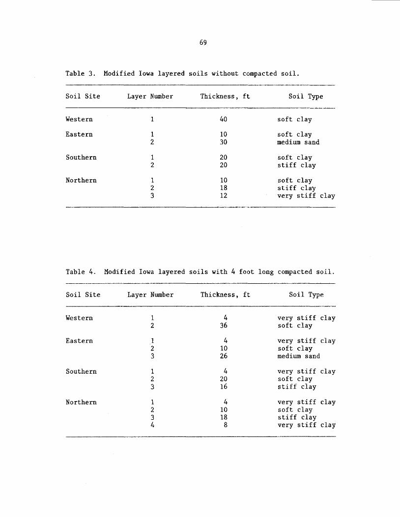
69
Table 3. Modified Iowa layered soils without compacted soil.
Soil Site Layer Number Thickness, ft Soil Type
Western 1 40 soft clay
Eastern 1 10 soft clay 2 30 medium sand
Southern 1 20 soft clay 2 20 stiff clay
Northern 1 10 soft clay 2 18 stiff clay 3 12 very stiff clay
Table 4. Modified Iowa layered soils with 4 foot long compacted soil.
Soil Site Layer Number Thickness, ft Soil Type
Western 1 4 very stiff clay 2 36 soft clay
Eastern 1 4 very stiff clay 2 10 soft clay 3 26 medium sand
Southern 1 4 very stiff clay 2 20 soft clay 3 16 stiff clay
Northern 1 4 very stiff clay 2 10 soft clay 3 18 stiff clay 4 8 very stiff clay
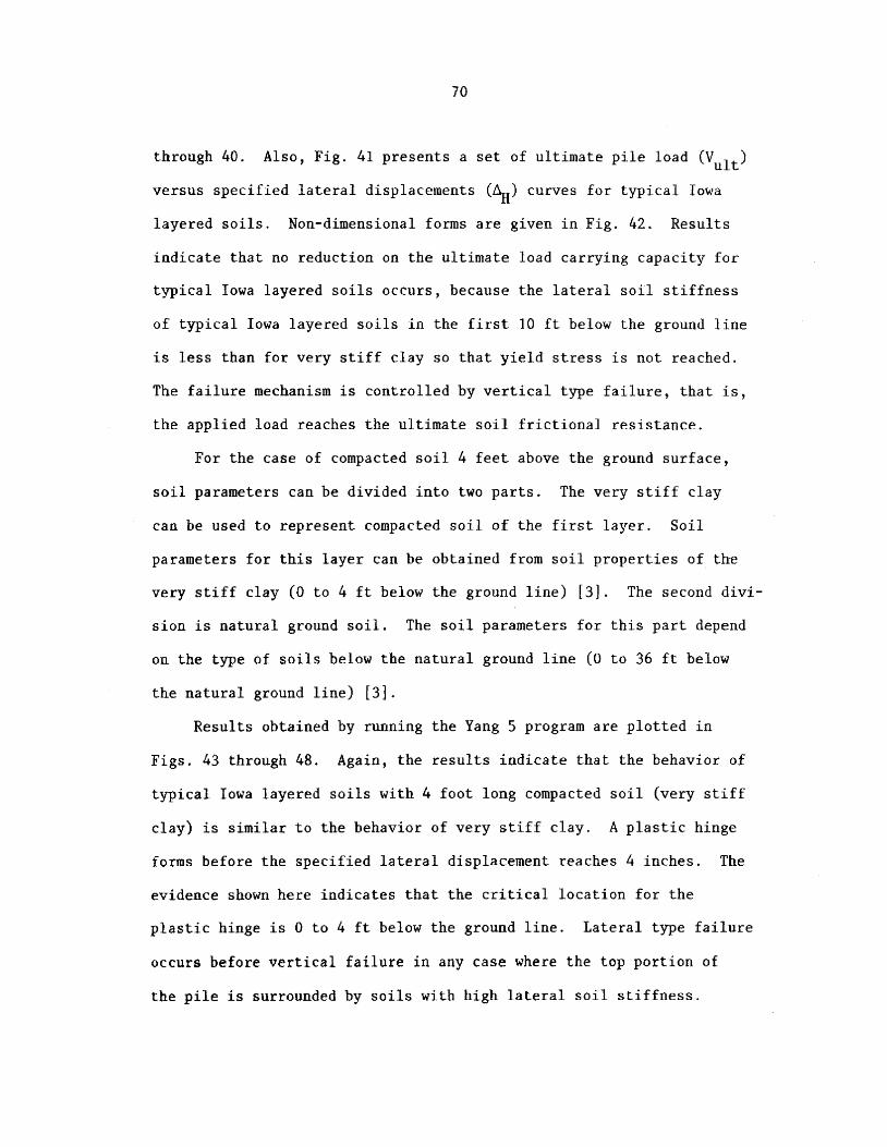
70
through 40. Also, Fig. 41 presents a set of ultimate pile load (Vult)
versus specified lateral displacements (~) curves for typical Iowa
layered soils. Non-dimensional forms are given in Fig. 42. Results
indicate that no reduction on the ultimate load carrying capacity for
typical Iowa layered soils occurs, because the lateral soil stiffness
of typical Iowa layered soils in the first 10 ft below the ground line
is less than for very stiff clay so that yield stress is not reached.
The failure mechanism is controlled by vertical type failure, that is,
the applied load reaches the ultimate soil frictional resistance.
For the case of compacted soil 4 feet above the ground surface,
soil parameters can be divided into two parts. The very stiff clay
can be used to represent compacted soil of the first layer. Soil
parameters for this layer can be obtained from soil properties of the
very stiff clay (Oto 4 ft below the ground line) [3]. The second divi
sion is natural ground soil. The soil parameters for this part depend
on the type of soils below the natural ground line (0 to 36 ft below
the natural ground line) [3].
Results obtained by running the Yang 5 program are plotted in
Figs. 43 through 48. Again, the results indicate that the behavior of
typical Iowa layered soils with 4 foot long compacted soil (very stiff
clay) is similar to the behavior of very stiff clay. A plastic hinge
forms before the specified lateral displacement reaches 4 inches. The
evidence shown here indicates that the critical location for the
plastic hinge is 0 to 4 ft below the ground line. Lateral type failure
occurs before vertical failure in any case where the top portion of
the pile is surrounded by soils with high lateral soil stiffness.

V1 a.. 1-1 ~
...
30
> 20
10
--<>-- 6H = 0.0 IN. --0- 6H = 1.0 IN. -..-. 6H = 2.0 IN. --&- ~ = 4.0 IN.
(0.0125 + 0.0083b) D---~~~~~~~~..__~~~~~~~-J--'-~~~~~~--0.00 0.0l 0.02 0.03
6v, FT
I
Fig. 37. Vertical load-settlement curves with specified lateral displacements, 6 (0, 1, 2, 4 in.), for western Iowa soil. H
" 1--'
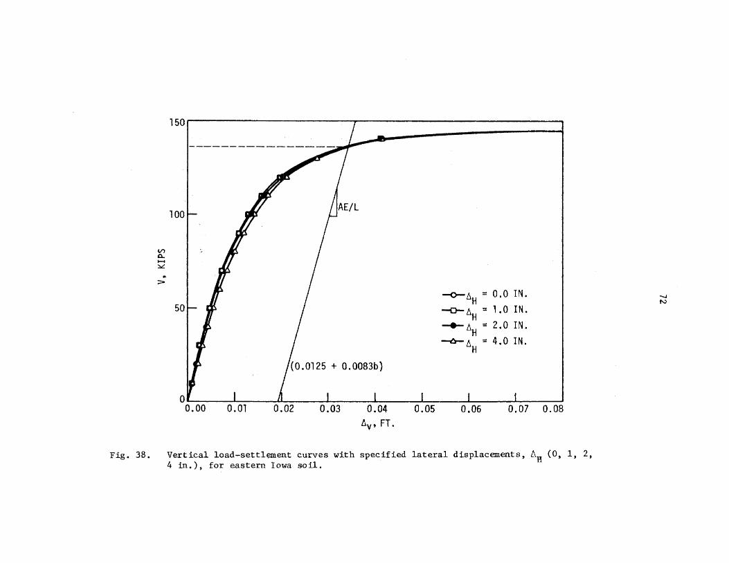
V') 0... 1-1 ::::..::::
"' >
150,--~~~~----------------~~~~~--~~~~~~--
100
-<>-LiH :: 0 • 0 IN •
-0-LiH = l .O IN. 50
-e- liH = 2 • 0 IN •
-o- li = 4.0 IN. H
0------------.-..·~-------~~--------~--__,,--~--------~ o.oo 0.01 0.02 0.03 0.04 6.v, FT.
0.05 0.06 0.07 0. 08
Fig. 38. Vertical load-settlement curves with specified lateral displacements, D.H (0, 1, 2, 4 in.), for eastern Iowa soil.
-.J N

100
V')
~ 50 ~
... >
I -o- ~H = 0.0 IN.
--o- ~H == 1.0 IN •.
__._ ~H = 2 • 0 IN.
--6- fiH • 4.0 IN.
0 O.o.0coo~--oJJ;:----t.F---,~~--~~~---:~~--_J----__j 0.01 0.02 0.05 0.06 0.03 0.04 0.07 ~v, FT.
Fig. 39. Vertical load-settlement curves with specified lateral displacements, bH (0, 1, 2, 4 in.), for southern Iowa soil.
-./ w
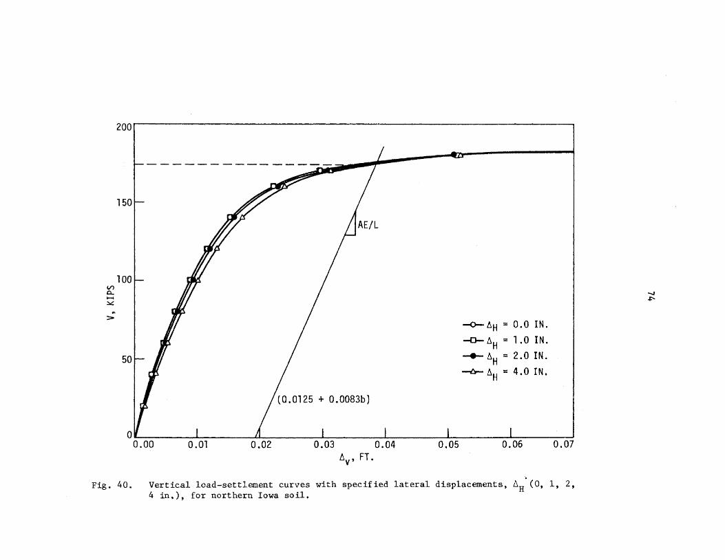
200
------------ Jlr4- il 42)- I 150
100 V) 0... I Ill I I -::w:::
"' > ~AH= 0.0 IN.
-o- fiH = 1 • 0 IN.
501- II I -+- ~H = 2.0 IN.
-b- ~H = 4.0 IN.
0--~~~---~~~~~~~~---~~~---~~~~---~~~---~~~--0.00 0.01 0.02 0.03 0.04 0.05 0.06 0.07
!.1v, FT.
Fig. 40. Vertical load-settlement curves with specified lateral displacements, b.H-. (0, 1, 2, 4 in.), for northern Iowa soil.
......... ~
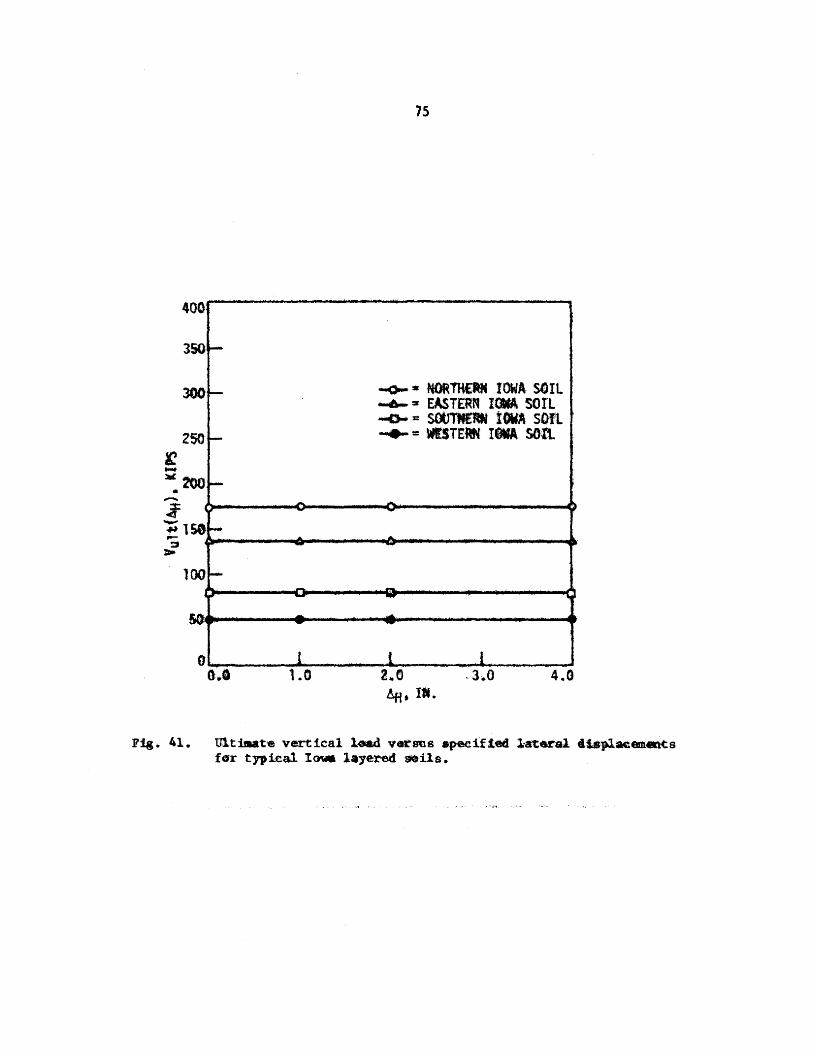
75
4 00
l so ....
- -..o-• NORTR£M IOWA SOIL -6-U EASTERN ICllfA SOil
300
-0-= SOOTNERN IOWA son. 50 .._ ....... = WISTERN IewA 50,n_
.... Ii
.... ..... - ~
se - & .... - - - -1 00 ....
~ - -.. - - ' -- - .... --- - -,,..
0 I I I 1.0 2 .. 0 ~ J.O 4 .. 0
Aft• lN.
Fig. 41. Ult:i.ate vertical load vet>sus apeeiH.ed loatual clupl.ac.E!lm«lts fer t yp i.eal IO"tt9 layered soils •
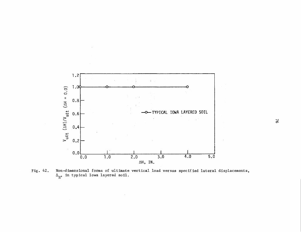
]~ig. 42.
1.:2
- l .P· 0
.o 0 ~ 0
0
II
:t: 0.8--
<l -.µ
0.6--~ =s
-<>-TYPICAL IOWA LAYERED SOIL > ........... .--.. :c
0.4-<J .... .µ o( ::3
> o.T I -0.0 I L l
0.0 1 .0 2.0 3.0 4.0 5.0 6H, IN.
Non-dimensional forms of ultiniate vertical load versus specified lateral displacements, .6H, in typical Iowa layered soil.
""-J
°'
77
Case (c) can be neglected in this investigation since the behavior
of case (c) with 10 foot long compacted soil is the same as it is for
case (b) or one layered type soil (very stiff clay).
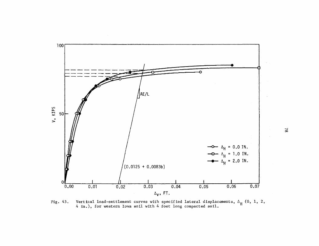
V') CL
100
~ 50 ..
>
(0.0125 + 0.0083b)
-0- l>.H = 0.0 IN.
~- tiH = l • 0 IN.
----- ~H = 2.0 IN.
Q·L· ~~~--lL-~~~LL---~~~~~~-::-.&::-:-~~--:;:-':-::-~~~~~~~ :o.oo 0.01 0.02 0.03 0.04 0.05 0.06 0.07
Fig. 43.
!>.v, FT.
Vertical load-settlement curves with specified lateral displacements, ll.H ( 0, 1, 2, 4 in.), for western Iowa soil with 4 foot long compacted soil.
......, 00
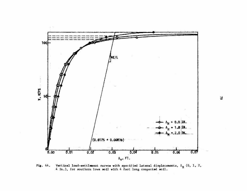
tlf'I a.. ~ • ,..
'tl .. 00 tfJ)1 -- o. o: ·tr~-~-,--
Av, FT.
....... Aw- • 0.-0 ~-ii. -G- AH• l.Ofll· ~-"1-~ --~-Z-.D lttt.._. -- C.• ~ , J
'(fJ1 __ _ ··cs~,°'-~
Fig. 44. Vertical load-set tl•ent curves with specified lateral displacements, tiH ( 0, 1, 2, 4 in.), for southern Iowa soil with 4 foot long compacted soil.
..... '°

200
150
. (/) a.. ....... ~ 100 .. >
I ,.P../
50._ Ill
0.01
I
/
0.02 0.03 0.04 '1v, FT.
0.05
-0-llH :::r 0.0 IN. I -6- ~H = l .. 0 IN .
-+- ~H = 2 . 0 IN.
0.06 0.07 0.08
Fig. 45. Vertical load-settlement curves with specified lateral displacements, 6H (O, 1, 2, 4 in.), for eastern Iowa so:il with 4 foot long compacted soil.
00 0
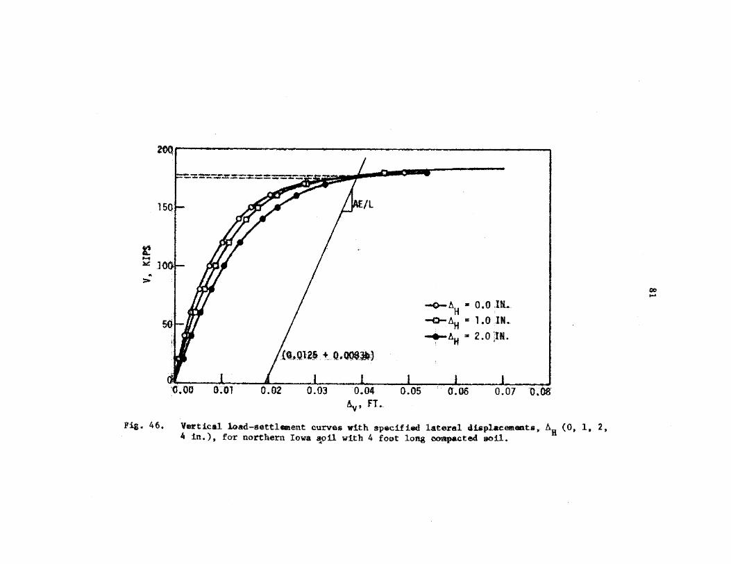
l! ~
lie J ...
>
;a.oo 0~01 0.03 0.04 Av, ft •.
0.05
-0-6H • 0.0 JL
-0-~H • 1.0 lN4_
~AH =- 2.0 llN.
0-.06 0.07 O~{Ml
Fil .. 46. Vertical load-settl•ent curves with specified lateral displacements, liH (0, 1, 2, 4 in.), for northern Iowa ~oil with 4 foot long 00mpac.ted soil.
00 .....
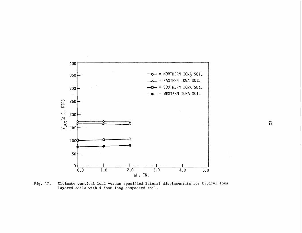
V1 '1.. -~
40
35
30
25
x 20 <l --.µ
«:>(
>~ 15
10
5
I
,_
1-
I-
,_ )-
W" , ~
1-
I
0.0
--o-- = NORTHERN IOW~ SOIL ---o-. = EASTERN IOWA SOIL --o-- = SOUTHERN IOWA SOIL ~ = WESTERN IOWA SOIL
.... ---0 - --6
--0 -- ---e -
I I I I 1.0 2.0 3.0 4.0 5.0
~H, IN.
Fig. 47. Ultimate vertical load versus specified lateral displacements for typical Iowa layered soils with 4 foot long compacted soil.
00 N
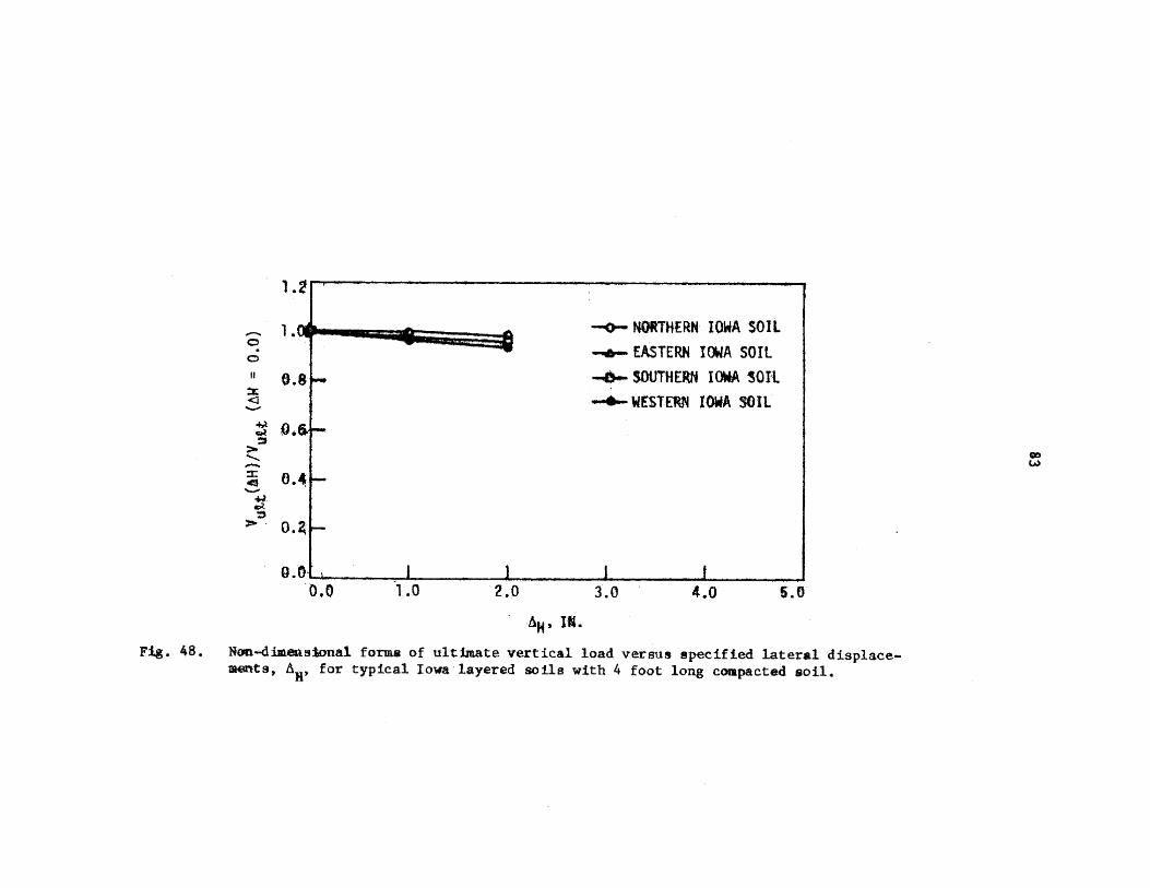
1.i
........ 1. 0
0
II 0.8 x <1 -
-M 0 ~ ..
>
"' -:t: 0.4. 4$ ......... ~. ~ :)
>. o.z
9.l'l ·o.o 1.0 2.0
-~, IN.
-o- NORTHERN IOWA SOil
.......,_ EASTERN IOWA SOIL
-6- SOUTHERN IOWA SOR ...._ WESTEM IOWA SOIL
3.0 4.0 5.0
Fig. 48. Non-dimensional forms of ultimate vertical load versus specified lateral displacelMt'lts, &8 , for typical Iowa.· layered soils with 4 foot long compacted soil.
go w
85
5. SUMMARY, CONCLUSIONS, AND RECOMMENDATIONS FOR FURTHER STUDY
5.1. Summary
The increasing popularity of integral abutment design for bridges
has been recognized by many state highway agencies. The current
length limitations in Iowa are based on a simple theoretical analysis
of the effects of thermal expansion and contraction of bridges on
piling stresses. At the present time, only short and moderate length
bridges without joints have been built with integral abutments.
Integral abutment bridges fall into two categories: non-skewed
and skewed. Site conditions determine whether or not a skewed bridge
is necessary. For skewed bridges with integral abutments, the movements
caused by thermal expansion and contraction are more complex than they
are for non-skewed bridges with integral abutments. These thermal
induced movements involve not only longitudinal direction, but transverse
direction and diagonal direction as well.
In July 1972, South Dakota State University issued a report on a
study conducted to investigate the stresses induced by thermal movements
in the girder and upper portion of steel bearing piles of integral
abutment-type bridges. In November 1981, North Dakota State University
issued a report based on tests conducted to observe the lateral movement
caused by annual temperature variations and to monitor temperature
induced piling stresses. In February, 1982, Iowa State University
published a study which summarized the variation in design assumptions
and length limitations among the various states in their approach to
the use of integral abutments. Also, an algorithm based on a state-
86
of-the-art nonlinear finite element procedure was developed and used
to study piling stresses and pile-soil interaction in integral abutment
non-skewed bridges.
In this study the highway departments of the states which use
integral abutments in bridge design were contacted in order to study
the extent of integral abutment use in skewed bridges and to survey
the different guidelines used for analysis and design of integral
abutments for skewed bridges. Survey responses indicated that 26
states use integral type abutments on skewed bridges. Most states
design integral abutments on skewed bridges on the basis of empirical
experience, and no theoretical analysis is introduced in design.
For integral abutments on skewed bridges, fifteen states orient
their piles with the web of the piles perpendicular to center line of
the abutment (Type 2b) so that bending will be primarily about the
strong axis. Thus, thermally-induced biaxial bending stresses are
introduced into the piles. However, the survey responses show that
most states ignore thermally-induced bending stresses caused by trans
verse movement. Kansas indicated that transverse thermal movement can
be eliminated by using shear keys on the bottom of the pile cap. The
major reasons given for selecting Type (2b) pile orientation are
• The restraint provided by the integral abutment reduces the
magnitude of the thermal movement. Orienting the pile with
its strong axis parallel to center line of the bearings gives
more rigidity for earthquake loads when liquification of
embankment is anticipated.
87
• Thermal expansion is actually very small, and the backfill
material, the abutment, and the piling seem to yield sufficiently
so that no distress is apparent. The piling is oriented to
resist the force of earth pressure from the abutment backfill
rather than the force of thermal expansion.
• Temperature forces act along the center line of the roadway,
not parallel to the pile web, and active soil pressure acts
against the strong axis of the pile. Temperature effects are
partially compensated for by predrilling for driven piles and
filling the voids with pea gravel or sand.
No special treatments are given to backfill and pile cap on
skewed bridges, and they might be constructed in the same way as
non-skewed bridges. As for the approach slab, it might be tied to the
abutment with dowels, or an expansion joint may be provided between
the approach slab and the bridge slab.
An idealized integral abutment was introduced by assuming that
the pile was rigidly cast into the pile cap and that the approach slab
offers no resistance to lateral thermal expansion. Also, it is more
conservative in design to ignore the passive soil and shear resistance
of the cap.
The influence of rotation at the pile head can be classified into
three categories: (a) fully restrained without rotation, (b) partially
restrained with some degree of rotation, (c) pinned, allowing rotation
but not translation. Two extreme cases which represent the upper
bound and lower bound of the ultimate pile load capacity will be
investigated. The results obtained from the theoretical analysis show
88
that if the piling is cast into the pile cap and a detailed design is
used to eliminate moment constraint at the joint, the ultimate vertical
load carrying capacity of the H pile after thermal movements can be
highly increased.
The effect of predrilled oversized holes was also discussed.
According to the survey responses, some states believe that the use of
predrilled oversized holes tends to make piles more flexible when they
are subject to thermal movements. Piling stresses are thus reduced,
and yield stresses are scarcely reached. Results obtained with the
Yang 5 program show that the above discussion is correct. If the
lengths of the predrilled oversized holes are at least 4 feet in the
ground, the ultimate vertical load carrying capacity of the H pile is
reduced by only 10 percent for 4 inches of specified lateral displacement
in very stiff clay.
The behavior of layered soils is also studied in this investiga
tion. In consultation with Iowa DOT soil engineers, we considered
four typical Iowa layered soils. In certain situations, pile is
embedded in highly compacted fill above the ground. Three different
cases of layered soils of varying length are discussed: (a) L = 0 ft,
(b) L = 4 ft and (c) L = 10 ft. The results obtained from case (a)
indicated that there is no reduction of ultimate vertical load capacity
of the H pile, because the lateral soil stiffness of case (a) in the
top 10 feet below the ground line is less than that of very stiff
clay. Hence, the yield stress of the pile is not reached. Indeed, in
case (b), which involves compacted soil 4 feet above the ground surface,
the results show that the failure mechanism is similar to that of very
89
stiff clay; a plastic hinge forms before the specified lateral displace
ment reaches 4 inches. Thus, if the top portion of the pile is sur
rounded by soils which possess high lateral soil stiffness, the lateral
type failure occurs before vertical type failure. Case (c) can be
neglected in this investigation, since the behavior of case (c) with
10 foot long compacted soil is the same as it is for case (b) or one
layered type soil (the very stiff clay).
5.2. Conclusions
Most states design integral abutment bridges on the basis of many
years of empirical experience, and no theoretical analysis is introduced
in design. The survey responses on integral abutment skewed bridges
received from state highway departments indicate that no serious
problems or distresses have been discovered as yet. Because of their
economic benefit and good serviceability, integral abutment bridges
have become very popular.
Pile orientations in integral abutments on skewed bridges will
cause thermally-induced biaxial bending stresses if the pile orienta
tions specified are of Type (2a) or (2b). One way to avoid this
thermally-induced biaxial bending stress is to use the pile orienta
tions specified as Type (la), (lb) and (3). The survey responses
indicated that 15 out of 26 states have adopted these pile orientations
so that bending will be primarily about the strong axis. Most states
do not consider the thermally-induced bending stress caused by transverse
90
movement. The major reasons given for selecting the Type (2b) pile
orientation are given in Section 3.
A previous report by the authors [3] showed that two types of
failure mechanism are possible for the pile-soil system: (a) lateral
type failure and (b) vertical type failure. Vertical type failure
usually occurs when the applied vertical load exceeds the ultimate
soil frictional resistance. Lateral type failure usually occurs
because of plastic hinge formation in the pile.
Preliminary results from this investigation showed that the
vertical load-carrying capacity of H piles with pinned pile heads is
not significantly affected by lateral displacements of 2 inches in
soft clay, stiff clay, very stiff clay, loose sand, mediwn sand, and
dense sand. However, in very stiff clay (average blow count of 50
from standard penetration tests), it was found that the vertical
load-carrying capacity of the H pile is reduced by about 20 percent
for 2 inches and 4 inches of lateral displacement. The vertical
load-carrying capacity is increased if the pile head is free to rotate.
The average AASHTO specified temperature change for Iowa is 40° F for
concrete bridges and 75° F for steel bridges. In this case, if a
thermal-induced movement of 2 inches was permitted, it would translate
into allowable lengths of 1400 feet for concrete bridges and 700 feet
for steel bridges without expansion joints. The allowable length for
fully restrained pile head is one-half of the allowable length for
pinned pile head. If the pile head is partially restrained, the
allowable length lies between these two limits. If a detailed design
91
can be achieved to eliminate moment constraint, the use of long integral
abutment bridges may be realized.
The results obtained from the investigation into the effect of
predrilled oversized hole indicated that the critical location for
plastic hinges falls in the range of 0 to 4 feet below the ground. If
the length of the predrilled oversized hole is 4 feet or more below
the ground, the vertical load-carrying capacity of the H pile is
reduced by 10 percent for 4 inches of specified lateral displacement
in very stiff clay. If the length of the predrilled oversized hole
falls in the range of 0 to 4 feet below the ground, the vertical
load-carrying capacity of the H pile will decrease as lateral displace
ment increases. The results shown here indicate that the predrilled
oversized hole affects the vertical load-carrying capacity of the H
pile.
Four different typical Iowa layered soils were selected and used
in this investigation. In certain situations, compacted soil (> 50
blow count in standard penetration tests) is used as fill on top of
natural soil. The critical conditions depend on the length of the
compacted soil. If the length of the compacted soil exceeds 4 feet,
the failure mechanism for the pile is similar to one in a very stiff
clay soil. That is, the vertical load-carrying capacity of the H pile
will be highly reduced as the specified lateral displacement increases.
92
5.3. Recommendations for Further Study
1. Because of annual temperature changes, a bridge superstructure
undergoes expansion and contraction, which in turn causes the
piles in integral abutment bridges to move back and forth. Thus,
the mathematical model used in this investigation must be modified
to accommodate loading and unloading of the pile during cyclic
loading.
2. Preliminary studies from this investigation showed that the fixity
condition at pile head has some influence on the vertical load
carrying capacity of H piles. Additional analytical studies
should focus on partially restrained pile head by taking into
account the stiffness of the superstructure.
3. When the effect of predrilled oversized holes is considered, a gap
element should be introduced into the soil model. This refined
model will represent the situation more realistically when lateral
displacement is such that the pile starts to push on the soil.
4. In skewed bridges with integral abutments, thermal movements
caused by temperature changes in most cases induce biaxial bending
in the pile. Thus, the mathematical model developed earlier must
be modified to cover problems in three-dimensions.
5. Maximum safe lengths for integral abutment bridges with concrete
and timber piles must be determined.
6. A scale model of a pile which represents the behavior of piles in
integral abutment bridges should be set up and tested in the
93
laboratory. The obtained experimental results can be used to
verify and refine the analytical model.
7. An actual bridge should be instrumented to monitor thermal movements
and piling stresses during several cycles of temperature change.
95
6. ACKNOWLEDGMENT
The study presented in this report was conducted by the Engineering
Research Institute of Iowa State University and was sponsored by the
Iowa Department of Transportation, Highway Division, through the Iowa
Highway Research Board.
The authors wish to express their gratitude to the bridge engineers
of all the fifty states for the 100 percent return rate on the survey
questionnaire. In particular, special thanks go to those who provided
additional information concerning their design and detailing procedures.
The authors also wish to extend sincere appreciation to the engineers
of the Iowa DOT for their support, cooperation, and counseling.
Special thanks go to Charles A. Pestotnik, Henry Gee, Vernon Marks,
and Kermet L. Dirks from the Iowa DOT, Bruce Johnson from the Federal
Highway Administration, and Wallace W. Sanders, Jr. from Iowa State
University.
97
7. REFERENCES
1. Lee, H. W. and Sarsam, M. B., "Analysis of Integral Abutment
Bridges," South Dakota Department of Highways, Pierre, South
Dakota, March 1973.
2. Gee, H., Engineer, Iowa Department of Transportation, Ames,
Personal Communications, 1982.
3. Wolde-Tinsae, A. M., Greimann, L. F. and Yang, P. S., Nonlinear
Pile Behavior in Integral Abutment Bridges, Final Report, DOT
Project HR-227, ISU-ERI-Ames 82123, February 1982.
4. Schupack, Morris, "Segmental Skewed Bridges with Square-Off
Abutments," ACI Journal Proceedings, Vol. 72, No. 9, Sept. 1975,
pp. 456-458.
5. Wallace, M. R., "Studies of Skewed Concrete Box-Girder Bridges,"
TRB Transportation Research Record 607, 1976.
6. Jorgenson, J. L., "Behavior of Abutment Piles in an Integral
Abutment Bridge,u Engineering Research Station, North Dakota
State University, November 1981.
7. McNulty, J. F., "Thrust Loading on Piles," Journal of the Soil
Mechanics and Foundation Division, ASCE, Vol. 82, No. SM4,
Paper 1081, 1956.
8. Davisson, M. T. and Gill, H. L., "Laterally Loaded Piles in a
Layered Soil System," Journal of the Soil Mechanics and Foundation
Division, ASCE, Vol. 89, No. SM3:63-84, May 1963.
98
9. Reese, L. C. and Matlock, H. , "Non-dimensional Solutions for
Laterally Loaded Piles with Soil Modulus Assumed Proportional to
Depth," Proceedings, 8th Texas Conference on Soil Mechanics and
Foundations Engineering, 1956.
10. Davisson, M. T., "Behavior of Flexible Vertical Piles Subjected
to Moment, Shear and Axial Load," Ph.D. Thesis, University of
Illinois, Urbana, Illinois, 1960.
11. Poulus, H. G. and Davis, E. H., Pile Foundation Analysis and Design,
John Wiley and Sons, Inc., New York, 1980.
12. Seed, H. B. and Reese, L. C., "The Action of Soft Clay Along
Friction Piles," Transactions, ASCE, Paper No. 2882, 1955.
13. Matlock, H. , "Correlations for Design of Laterally Loaded Piles
in Soft Clay," Proceedings of the Offshore Technology Conference,
Houston, Texas, 1974.
14. Reese, 1. C. and Welch, R. C., "Lateral Loading of Deep Foundations
in Stiff Clay," Journal of the
ASCE, Vol. 101, No. 477:633-649, July 1975.
15. Reese, L. C., Cox, H. R., and Koop, F. D., "Analysis of Laterally
Loaded Piles in Sand," Proceedings of the Offshore Technology
Conference, Houston, Texas, 1974.
16. Vijayvergiya, V. M., "Load-Movement Characteristics of Piles,"
Proceedings, Ports 1977 Conference, ASCE, Long Beach, California,
March 1977.
17. D'Appolonia, Z. and Rosmualdi, J. D., "Load Transfer in End-Bearing
Steel H-Pile," Journal of the Soil Mechanics and Foundations
Division, ASCE, SM2:1-25, March 1963.
99
18. Alizadeh, M., and Davisson, M. T., "Lateral Load Tests on Piles-
Arkansas River Project," Journal of Soil Mechanics and Foundations
Division, ASCE, SM5:1583-1864, September 1970.
19. Bhushan, K., Maley, S. C., and Fong, E.T., "Lateral Load Tests
on Drilled Piers in Stiff Clays," Journal of the Geotechnical
Engineering Division, ASCE, Vol. 105, No. G78:969-985, August
1979.
20. Reese, L. C., Touwa, F. T., and O'Neill, M. W., "Behavior of
Drilled Piers under Axial Loading," Journal of the Geotechnical
Engineering Division, Vol. 102, No. G75:453-510, May 1976.
21. Cassano, R. C., Chief, Office of Structures Design, California
Department of Transportation, Sacramento, Letter of Correspondence
854, July 1982.
22. Desai, C. S. and Christian, J. T., Numerical Methods in Geotechnical
Engineering, 1st edition, McGraw-Hill Book Company, New York,
1977.
23. Anderson, G. H., Bridge Development Engineer, Wisconsin Department
of Transportation, Madison, Wisconsin, Personal Communication,
July 1982.
24. Hourigan, E. V., Deputy Chief Engineer in Structures, New York
Department of Transportation, Albany, New York, Personal Communica
tion, July 1982.
25. Wilson, K. C., Chief Bridge Engineer, South Dakota Department of
Transportation, Pierre, South Dakota, Personal Communication,
July 1982.
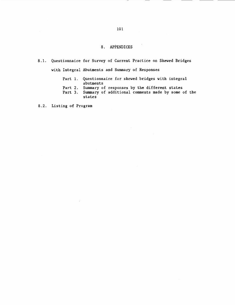
101
8. APPENDICES
8.1. Questionnaire for Survey of Current Practice on Skewed Bridges
with Integral Abutments and Summary of Responses
Part 1. Questionnaire for skewed bridges with integral abutments
Part 2. Summary of responses by the different states Part 3. Summary of additional comments made by some of the
states
8.2. Listing of Program
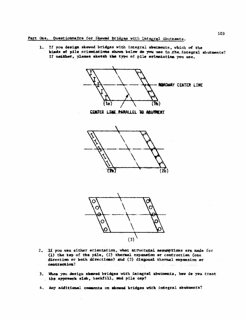
lOJ Put One. Questionn•.it'e f&r S~~ fr;iQ.ges with Int;!g,r9l Abut;:men.ts.
1. If yo~ del!riga skewed b·ri4ges with integral o.r.aents " wliicll 6f the kiat!B ef pile oriaitt.at~otta •howl\ belew ..to -,OU \Ille. in ..zhe...integral abut:ments? If n-..ltd,, p;l.au• akeHa , .. type of pile ·~•t.a.U.oa you \lse.
· 1al
"'1ti U&E-HIAtlEl 10 ... ~
\ ·-·~·
\ ( 3)
2. _ .U you .u•e.. eiehfl!r e:rie,ntat:lu,_ ~t;. •truiet.\\Ql --~'lt10\$ are. ma4e for (l) t.h1! tep of t-tte pi.le!J (2) t"he"l"'IMll e:rp&Nfd:an H' contraetiMt. (one dire£tioe or ltoth .W.rectioas) 4n.d (3) di~ thermal eKp-.sion or eau.-1o'A1.
l. Whea )TG'll ct.sign .._,eel bridges with i..at:egr-4 at.tlll!lnta., hew de you treat tjl_ft a~ii slab,, baekfill,. ,aacl pU.-~ cap'l
4. Arty addittaaal e-.enta Oft ...,.. 1u.•i'flgas ritl\ itt«egral ae1dments'?
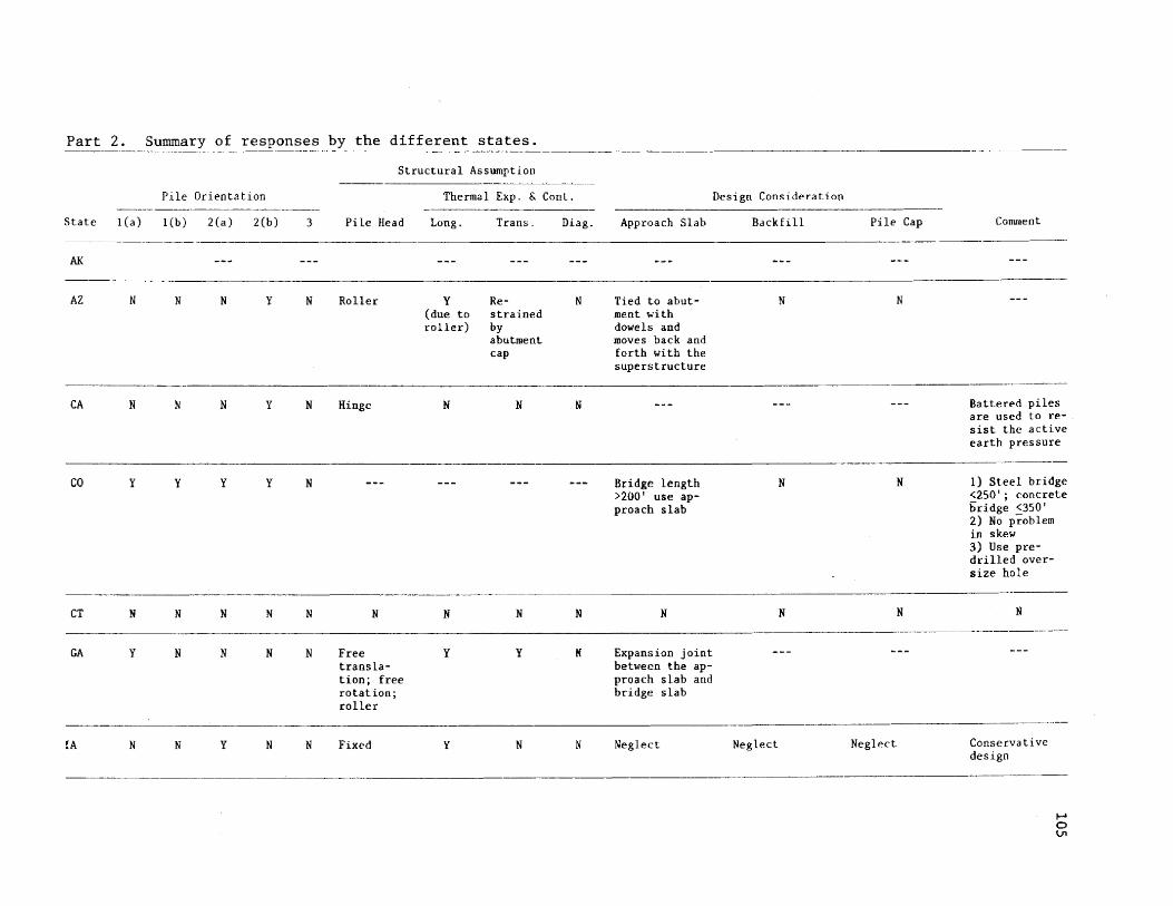
Part 2. Summary of responses by the different states.
Structural Assumption
Pile Orientation Thermal Exp. & Cont. ----~~~-~-----
State 1 (a) l(b) 2(a) 2(b) 3 Pile Head Long. Trans. Diag.
AK
AZ N N N y N Roller y Re- N (due to strained roller) by
abutment cap
CA N N N y N Hinge N N N
co y y y y N --- --- --- ---
CT N N N N N N N N N
GA y N N N N Free y y N trans la-tion; free rotation; roller
CA N N y N N Fixed y N N
Design Consideration
Approach Slab Backfill
Tied to abut- N ment with dowels and moves back and forth with the superstructure
--- ---
Bridge length N >200' use ap-proach slab
N N
Expansion joint between the ap-proach slab and bridge slab
Neglect Neglect
-------Pile Cap
N
---
N
N
Neglect
Conuuent
Battered piles are used to re-sist the active earth pressure
---
1) Steel bridge <250'; concrete bridge ~350' 2) No problem in skew 3) Use pre-drilled over-size hole
----
N
Conservative design
~ 0 Ln
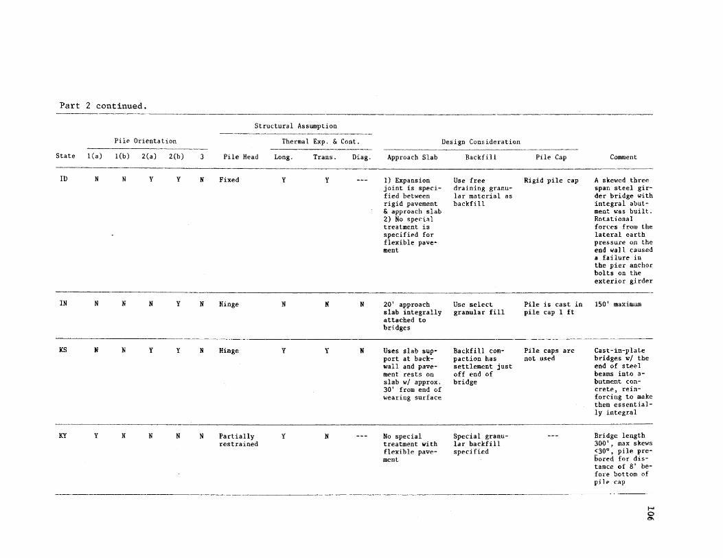
Part 2 continued.
Structural Assumption
Pile Orientation Thermal Exp. & Cont. Design Consideration
State l(a) l(b) 2(a) 2(b) 3 Pile Head Long. Trans. Diag. Approach Slab Backfill Pile Cap Comment
ID N N y y N Fixed y y --- 1) Expansion Use free Rigid pile cap A skewed three joint is speci- draining granu- span steel gir-fied between lar material as der bridge with rigid pavement backfill integral abut-& approach slab ment was built. 2) No special Rotational treatment is forces from the specified for lateral earth flexible pave- pressure on the ment end wall caused
a failure in the pier anchor bolts on the exterior girder
IN N N N y N Hinge M N N 20' approach Use select Pile is cast in 150' maximum slab integrally granular fill pile cap 1 ft attached to bridges
KS N N y y N Hinge y y N Uses slab sup- Backfill com- Pile caps are Cast-in-plate port at back- paction has not used bridges w/ the wall and pave- settlement just end of steel ment rests on off end of beams into a-slab w/ approx. bridge butment con-30' from end of crete, rein-wearing surface forcing to make
them essential-ly integral
KY y N N N N Partially y N --- No special Special granu- --- Bridge length restrained treatment with lar backfill 300', max skews
flexible pave- specified 90(), pile pre-ment bored for dis-
tance of 8' be-fore bottom of pile cap
,._. 0
°'
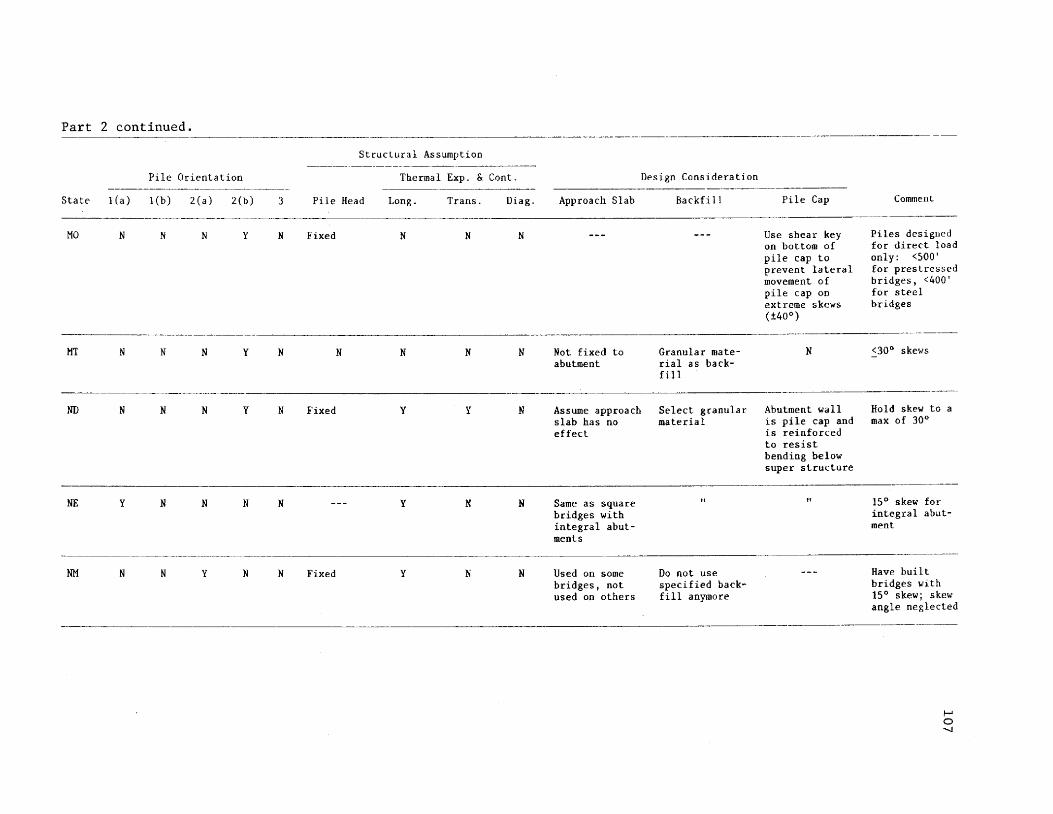
Part 2 continued.
Structural Assumption ---~L-------------·
Pile Orientation Thermal Exp. & Cont.
State l(a) 1(b) 2(a) 2(b) 3 Pile Head Long. Trans. Diag.
MO N N N y N Fixed N N N
HT N N N y N N N N N
ND N N N y N Fixed y y N
NE y N N N N --- y N N
NM N N y N N Fixed y N N
Design Consideration
Approach Slab Backfill
--- ---
Not fixed to Granular mate-abutment rial as back-
fill
Assume approach Select granular slab has no material effect
Same as square II
bridges with integral abut-men ts
Used on some Do not use bridges, not specified back-used on others fill anymore
Pile Cap
Use shear key on bottom of pile cap to prevent lateral movement of pile cap on extreme skews (±40°)
N
Abutment wall is pile cap and is reinforced to resist bending below super structure
II
---
Comment
Piles designed for direct load only: <500' for prestressed bridges, <400' for steel bridges
<30° skews
Hold skew to a max of 30°
15° skew for integral abut-ment
Have built bridges with 15° skew; skew angle neglected
I-' 0 -....J
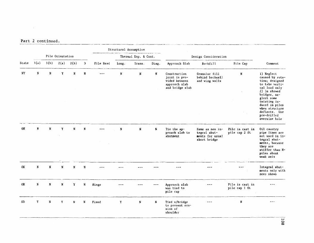
Part 2 continued.
Structural Assumption
Pile Orientation Thermal Exp. & Cont. Design Consideration
State 1 (a.) l(b) 2(a) 2(b) 3 Pile Head Long. Trans. Diag. Approach Slab Backfill Pile Cap Comment
NY NI N y N N --- N N N Construction Granular fi 11 N 1) Neglect joint is pro- behind backwall caused by rota-vided hetween and wing walls tion; designed approach slab to take verti-and bridge slab cal load only
2) fo skewed bridges, ne-glect some twisting in-duced in piles when structure deflects. Use pre-dlrilled oversize hole
OH ,NI N y N N --- N N N Tie the ap- Same as non in- Pile is cast in Oil country proach slab to tegral abut- pile cap 2 ft pipe lines are abutment ments for usua 1 not used in in-
short bridge tegral abut-ments, because they are stiffer than H-piles about weak axis
OK NI N N N N --- --- --- --- --- --- --- Integral abut-ments only with zero skews
OR NI N N y N Hinge --- --- --- Approach slab --- Pile is cast in was tied to pile cap 1 ft pile cap
SD y N y N N Fixed y N N Tied w/bridge --- N to prevent ero-sion of shoulder
r-a 0 00
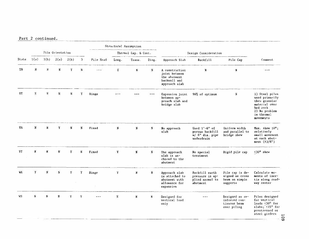
Part 2 continued. ~·----- ~~T-~-
Structural Assumption -~ ------------------~
Pile Orientation Thermal Exp. & Cont. Design Consideration
Slate l(a) l(b) 2(a) 2(b) 3 Pile Head Long. Trans. Diag. Approach Slab Backfill Pile Cap Comment -~-----·----------
TN N N N y N --- y N N A construction N N joint between the abutment backwall and approach slab
UT N N N N y Hinge --- --- --- Exp ans ion joint 96% of optimum N 1) Steel piles between ap- used primarily proach slab and thru granular bridge slab material over
bed rock 2) No problem in thermal movements
VA N N y N N Fixed N N N No approach Used l'-6" of Uniform width Max. skew 10°; slab porous backfill and parallel to relatively
w/ 6" dia. pipe bridge skew small movement underdrain at each abut-
ment (±3/8")
VT N N N y N Fixed y N N The approach No special Rigid pile cap <30° skew slab is an- treatment chored to the abutment
WA y N N y y Hinge y N N Approach slab Backfill earth Pile cap is de- Calculate mo-is attached to pressure is ap- signed as cross ments of iner-abutment with plied normal to beam on simple tia along road-allowance for abutment supports way center expansion
ws N N N y y --- N N N Designed for --- Designed as re- Piles designed vertical load inforced con- for vertical only tinuous beam loads <30° for
over pi ling slabs;-<15° for prestressed or steel girders
~ 0 \0
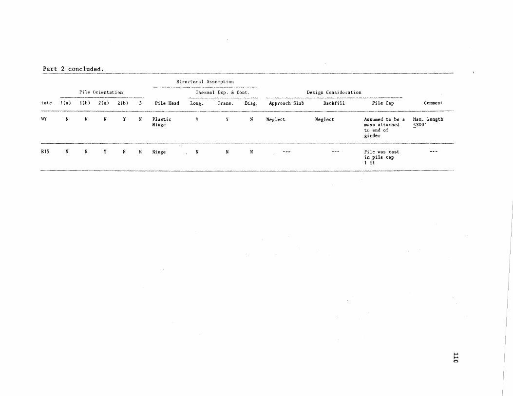
Part 2 concluded.
Pile Orientation
tate l(a) l(b) 2(a) 2(b) 3
WY N N N y N
RlS N N y N N
Structural Assumption
Pile Head
Plastic Hinge
Hinge
Thermal Exp. & Cont.
Loni~. Trans. Diag.
y y N
N N N
Design Consideration
Approach Slab Backfill
Neglect Neglect
Pile Cap
Assumed to be a mass attached to end of girder
Pile was cast in pile cap 1 ft
Comment
Max. length 900 1
..... ..... 0
Part 3. Summary of Additional Comments Made by Some of the States
Wisconsin
The pile orientation used in Wisconsin is based on past experience
and site soil conditions.
In 1971, a study of abutments supported on piles driven through
soft compressible soil showed that they have a tendency to tilt toward
the backfill when the shearing strength of the soil is exceeded because
of super-imposed embankment loads. To help prevent tilting of the
abutments, the study recommended nondisplacement type piles with
strong-axis orientation to resist bending forces.
The use of Type (la) and (2a) abutments dates back some 20 years,
and in general performance has been good. On larger skews (greater
than 30 degrees), occasional cracking or spalling of the end diaphrams
around the girders and/or at the construction joint has been observed.
At present it is debatable whether this results from temperature
movements, pile orientation, or the restraint of the integral abutments.
Selection of standard abutment types is described in the attached
sheets (Bridge Design Manual). Type Al with fixed seat, which is
listed in the manual, appears to be equivalent to the Type (2b) integral
abutment discussed earlier. At this time the change of pile orientation
for added flexibility to accommodate thermal expansion is not considered
[23].
111

PROCEDURE
Manual SUDJ•ct
Bridge Design Chapter l2 - Abutments
Upper Limit of Stru.C'tUral Excavation
Lateral Limit of Structural. Excavation
Pipe Underdrain (Location may vary)
Bottom of Footing
W'"A Granular Backfill Between Inside Faces of Wings
l2.7 SELECTION OF STANDARD ABUTMENT TYPES
From past experience and investigations the following types of abutments are generally most suitable and economical for the given conditions. Although pil.es are shown for each abutment type, spread footings may be utilized. The following chart is a guide only a.ud need not be rigidly followed.
11
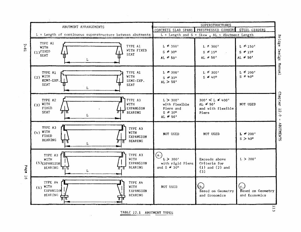
"' I m I-'
"tl ni
(J'Q ~
I-' <n
ABUTMENT ARRANGEMENTS ' SUPERSTRUCTURES CONCRETE SLAB SPANS PRESTRESSED GIRDER~ STEEL GIRDERS
L = Length of continuous superstructure between abutments L = Length and S = Skew , AL = Abutment Length
TYPE Al ~ j\ WITH TYPE Al L ~ 300' L ~· 300' L ~ 150'
( l) rIXED ~ : ~i~~ FIXED S "' 30° S ,,,_ 15° S ,._ lSo
SEAT AL -5- 50' AL ~ 50' AL ~SO' L ..
TYPE Al ~ j TYPE Al L ,._ 300' L "'300' L ,.: 200' ( 2) WITH WITH s ~ 300 S '/If. 400 S ~ 40°
SEMI-EXP. SEMI-EXP. AL> 50' SEAT SEAT
L
TYPE A2 ~ ~TYPE A3 L > 300' 300' < L fl' 400' ( 3) WITH WITH with flexible AL ~ 50' NOT USED
FIXED -: ~ EXPANSION Piers and and with flexible SEAT BEARING S ~ 30° pj_ers
L AL ~SO'
TYPE A3 ,1 I" TYPE A3
( 4) WITH ~ ' WITH NOT USED NOT USED L ~ 200' FIXED EXPANSION 0 s > 40
BEARING 1f nr BEARING - L -
TYPE A3 lli [1 TYPE: A3 8 WITH WITH L > 300 1 Exceeds above L > 200 1
( 5 lEXPANSIOH ~ ~ EXPANSION with rigid Piers Cd teria for BEARING
1
BEARING and S • 30° (1) and (2) and
.- L .... 1 (3)
TYPE A4 "I • ... TYPE A4 n n ( 6) WITH I I WITH NOT USED ~ \2,)
EXPANSIOt , EXPANSION Based on Geometry Based on Geometry BEARINC ' l BEARING and Economics and Economics
' . TABLE J2.l ABUTMENT TYPES
,._. I-' .......,
tD '1 I--'• p,
OQ lb
0 lb IA t-'•
~ ~ Ill ::l i:: PJ I-'
(")
:::r' '11 'rj rt CD ~
..... t'-.)
0
~ c t-J
~ z t-J (/)
... ~, lt9 i Manual ,_,,:l
Bridge Section
TABLE 12.l - Abutment !ypes (Footnotesl
PROCEDURE Num1:>er
Sub1ect
Chapter 12.0 - Abutments
a. Consider the flexibility of the piers when choosing these abutment types. Only one expansion bearing is needed if the structure is capable of expanding easily in one direction. With rigid piers, synnnetry is important for getting equal expansion movements and minimizing the forces on substructures.
b. For two-span prestressed girder bridges, it may be necess~ry to investigate both sill type and semi-retaining type abutments. For example, semiretaining abutments with 45-inch girders may be more economical than sill abutments with 54-inch girders. The sill abutment is usually more economical than a semi-retaining, if both are feasible for a given girder depth.
c. For two-span steel structures with long spans, the semi-retaining abutments are usually more economical than sill abutments due to the shorter bridge lengths.
D.ate
OT 1 12-77 ...... 17 "'
114
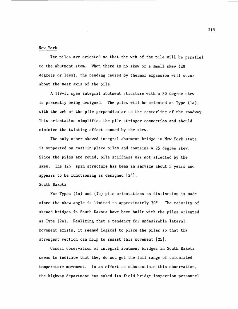
New York
The piles are oriented so that the web of the pile will be parallel
to the abutment stem. When there is no skew or a small skew (20
degrees or less), the bending caused by thermal expansion will occur
about the weak axis of the pile.
A 119-ft span integral abutment structure with a 30 degree skew
is presently being designed. The piles will be oriented as Type (la),
with the web of the pile perpendicular to the centerline of the roadway.
This orientation simplifies the pile stringer connection and should
minimize the twisting effect caused by the skew.
The only other skewed integral abutment bridge in New York state
is supported on cast-in-place piles and contains a 25 degree skew.
Since the piles are round, pile stiffness was not affected by the
skew. The izs• span structure has been in service about 3 years and
appears to be functioning as designed [24].
South Dakota
For Types (la) and (lb) pile orientations no distinction is made
since the skew angle is limited to approximately 30°. The majority of
skewed bridges in South Dakota have been built with the piles oriented
as Type (2a~. Realizing that a tendency for undesirable lateral
movement exists, it seemed logical to place the piles so that the
strongest section can help to resist this movement (25}.
Casual observation of integral abutment bridges in South Dakota
seems to indicate that they do not get the full range of calculated
temperature movement. In an effort to substantiate this observation,
the highway department has asked its field bridge inspection personnel
115
to place reference points on structures of this type and take measure
ments at temperature extremes. However, this effort was only initiated
during the past spring, and it might be several years before any
assumptions can be made.
llt
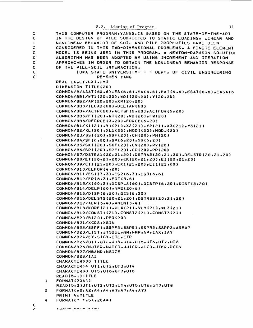
c c c c c c c c c c
c
8.2. Listing of Program 11
THIS COMPUTER PROGRAMtYANGS.IS BASED ON THE STATE-OF-THE-ART IN THE DESIGN OF PILE SUBJECTED TO STATIC LOADING. LINEAR AND NONLINEAR BEHAVIOR OF SOIL AND PILE PROPERTIES HAVE BEEN CONSIDERED IN THIS TWO-DIMENSIONAL PROBLEMS. A FINITE ELEMENT MODEL IS 3EING USED IN THIS PROGRAM. A NEWTON-RAPHSON SOLUTIOI ALGORITHM HAS BEEN ADOPTED BY USING INCREMENT AND ITERATION APPROACHES IN ORDER TO OBTAIN THE NONLINEAR BEHAVIOR RESPONSE OF THE PILE-SOIL INTERACTION.
IOWA STATE UNIVERSITY- DEPT. OF CIVIL ENGINEERING PE-SHEN YANG
REAL LX.LV.LXl.LYl DIMENSION TITLE<20J COMMON/B/ASATC60.6>.ES(6,6J.EAC6.6),EAT(6,6).ESAT(6,6).EASA(6 COMMON/BBl/WT1(20e20JeW01(20w20J,YC20.20J COMMON/882/AR(20.20),XR(20.20J. COMMON/8B3/TLDA0(60J.DELTAP(60) COMMON/BB4/ACTP(60)eACTSF(6,20)eACTFOR(6e20) COMMON/BB5/FT(20J.WT(20leWD(20J,FWC20) COMMON/BB6/DFORCE<3•20).FORCE(6•20> COMMON/Bl/Xl(2ll•VlC21),X2(21),y2(21J•X3C21).Y3(21) COMMON/B2/XL(20).XL1(20J.NODI(20)•NOOJ(20) COMMON/B3/SSl(20JwSSFC20l•CHl20)tPHC20) COMMON/B4/SF(6.20l.SP(6.20),SS(6,20) COMMON/B5/SKl(20J.SKF(20).CV(20J.PV(20) COMMON/B6/SP1(20)eSPF(20JwCPC20l.PP(20) COMMON/87/DSTRA1(20.21•20J.DSTRA2(20.21•20),DELSTR(20e21,20) COMMON/88/ET(20•21•20)eEKl20•21•20l.EI,20.21•20J COMMON/B9/ET1C21•20)eEK1(21•20>•EllC21,20) COMMON/Bl0/ELFOR(4,20J COMMON/Bll/ES1(3,3)wE52(6.3l•ES3<6•6l COMMON/B12/ER(6.3),ERT(3e6) COMMON/813/X(60e2)e0ISPLA(60),0lSTP(6e20JeOISTl3•20J COMMON/B14/DELPC60)•NPEC20•6) COMMON/Bi5/DISP(6.20i.DIS(6.20i COMMON/Bl5/DELSTS(20.21.20J.DSTRSS(20.21•20) COMMON/Bl7/ALN(3,4l.ANLN(3,4) COMMON/818/KODE(21JeULXl21),VLY(21J.WLZl21) COMMON/Bl9/CONST1(21J,CONST2C2lleCONST3(21) COMMON/B20/BC20),PERC20) COMMON/621/XCOSeXSIN COMMON/822/SSPFleSSPF2.SSPRleSSPR2.SSPP2.AREAP COMMON/823/LIST.jTSOIL.NM.NMP.NP.IAX.IAY COMMON/824/EV.SIGY•ETE.ETP COMMON/B25/UTl.UT2•UT3.UT4.UT5.UT6eUT7eUT8 COMMON/826/NJTER.NJICR,JJICReJICR,JTEReDCOV COMMON/B27/NBAND•NSIZE COMMON/828/IAZ CHARACTER*80 TITLE CHARACTER*4 u11.ur2.uT3.UT4 CHARACTER*8 UT5eUT6.UT7.UT8 READ(5el)TITLE
l FORMAT<20A4) REA0(5e2JUTleUT2.UT3wUT4•UT5.UT6.UT7.UT8
2 FORMAT(A2eA2,A4.A4.A7,A7eA4.A7) PRINT 4.TITLE
4 FORMAT(' •,sx.20A4)
c c c
c c c
c c c c c c
c c c c c
c c c c
c c
2~0
235
CALL OATAl
INPUT SOIL DATA
CALL DA TA2
INPUT NODAL INFORMATIONeCRITERIA OF CONVERGENCE
CALL OATA3
START DO-LOOP TO APPLY INCREMENTAL LOADING ON TANGENTIAL STRUCTURE STIFFNESS MATRIX
INITIALIZE THE NUMBER Of CYCLES
NJ I CR=O NJTER=O NJ 1 CR=N .J ICR+ 1 IAZ=O N.JTER=O N.JTER=NJTER+l
ZERO OUT BANDED STRUCTURAL STIFFNESS MATRIX.ASAT;ANO THE INCREASED DISPLACEMENT MATRIX.OISPLA;THE UNBALANCED NOOAL FORCE.DELP.
NSIZE=NP NBAND=6 00 240 IR=l.NSIZE OISPLA(IR>=o.o DELP <IR >=O .o DO 240 IC=l•NBANO
240 ASATCIR.IC>=o.o
2't5
START DO-LOOP TO BUILD UP TANGENTIAL STRUCTURE STIFFNESS MATRIX
DO 21f5 N= 1 ,NM CALL UPDATE(l.N) CALL ELSPRF(l•N> CALL ELSPFFO•N> IFtN.EQ.NM>THEN CALL ELSPPF(l•N> ENO IF CALL ELDEDPCN) CALL STRAIN(N) CALL STRESSCN) CALL ELOEFR(N) CALL EL EA K I( N ) CALL ELTRAM(N) CALL ELDESHN) CALL ELSTIF (4.N) CALL EL TEMP ( N) CALL ELGLOS,Nl CALL ELASSM(N) CONTINUE
DURING THE ITERATION.COMPUTE THE ACTUAL INCREMENT FORCE
118
c c c
c c c
c c c
c c c
c
c
250 00 250 I= 1 .NP DELP(l)=DELTAP(IJ-ACTP(I) 119
INTRODUCE KINEMATIC CONSTRANTSlGEOMETRIC BOUNDARY CONDITIONS)
CALL CONSTR
SOLVE FOR INCREASED DISPLACEMENT : DELP=ASATOOISPLA
CA~L BANSOL(l•ASAT•DELP.NSIZE•NBAND) CALL BANSOL(2.ASAT.DELP.NSIZE.NBAN0) DO 255 I=l•NSIZE
255 DISPLAlI>=DELP(I)
260
262
265
315
DO 260 I=l.NMP X2 ( I) ::x l (I )
Y2,I>=Y1Cll I A l=3:::I -2 IA2=3*I-1 IA3=3*I XllAl.ll=X(IAl.l)+OISPLA(lAl) XllA2.l)=X(IA2.l)+OISPLA(IA2) X(IA31l)=XlIA3el)+OISPLA(lA3) Xl(l)=Xl(l)+OISPLA(IAl) Yl(l)=Yl(l)+OISPLA(IA2) CON TI N\JE DO 262 l=l•NP ACTP<I>=o.o
CALCULATE ELEMENT FORCES IN TERMS OF LOCAL COORDINATE
DO 265 N=l.NM CALL UPDATE(l•N> CALL ELTEMP(N) CALL ELOI SP(N). CALL ELSPFR(N) CALL UPDATE ( 1 1 N J CALL ELOEOPCNJ CALL STRAIN(N) CALL STRESS(N) CALL ELDEFR(NJ CALL ELTRFCNJ CALL ELTRAM(N) CALL ELMFOR <N)
ASSEMBLE EQUILIBRIUM ACTUAL FORCES AT EACH NODE IN GLOBAL
CALL UPDATE ( l 1N > CA LL EL TEMP (N) CALL ELACTP(N) CONTINUE IF(NJTER.LE.2) GO TO 310 TEST FOR DISPLACEMENT CONVERGENCE DO 315 I=l.NP DISCOV=X<l•l>-X<I.2) IF(ABS(OISCOVJ.GT.ABS(DCOV)) GO TO 310 PRINT NODAL DISPLACEMENT IN TERMS OF GLOBAL COORDINATE PRINT 35.NJTER
~5 FORMAT('O' .5X. 1 NODAL DISPLACEMENT IN TERMS OF GLOBAL AXIS'
c c c
c
1 •x-cooRo•.•v-cooRo• 62 FORMAT<//.5X.A9.10X.A8.1ox.As.1ox.A10.1ox.A7elOX.A7)
317 64
68
DO 317 I=l•NMP IB1=3*I-2 182=3*1-1 lB J;3;C;I PRINT 64.1.xc1a1.1l.X(IB2.1J.X(183•l).x1(1).Yl(I) FOAMAT(/.1ox.14.ax.F10.5.ax.F10.s.1ox.F10.5e2(7X.Fl0.5)) PRINT 68•'ELEMENT FORCES IN TERMS O~ LOCAL AXIS' FORMAT<• •.sx.A37)
12(
1 2
70
PRINT 70.'MEMNO'e'AXAIL FORCE(KIPS)•,•SHEAR FORCECKIPS)'• 'END MONENT(FT-KIPS>'•'AXIAL FORCECKIPS)'•'SHEAR FORCE CKIPSJ•,•ENO MONENTCFT-KIPS)' FORMAT(///5XtA5.3XtA17t3X.Al7e1XeA19.3X.Al7.1XtA19.1X1Al9l DO 318 I=l tNM
72
74
75 318
310 325
76
320
PRINT 72tltCFORCE(Ltl)tL=l•6> FORMAT(' '•4X.I5t6(2X.F18.5)) PRINT 74.CSF(LeIJ•L=lt6) FORMAT(' •,9X,6(2X.F18e5J) PRINT 75,(S$(L•l>•L=1•6) FORMAT(' 1 t9Xe6(2X.F18.5J) CONTINUE GO TO 320 00 325 I=l ,NP xu.21=x< 1.1 > IF(NJTER.LT.JTER> GO TO 235 PRINT 76•'THE CONVERGENCE IS NOT REACHED' FORMA H I I 1A30) GO TO 6000
COMPUTE FORCE INCREMENT TO BE APPLIED
CALL FEOEIC IF(IAZ.EQ.ll GO TO 230 IF(NJICR.LT.JjICR> GO TO 230 PR!NT 78,•ACTUAL NODAL LOADS IN TERMS OF STRUCTURAL AXIS'
18 FORMAT(' '•5XtA46) PRINT 801 1 JOINT 1 • 1 X-LOAD•KIPS'•'Y-LOAD•KlPS•,•Z•LOAD•FT-KIP~
80 FORMAT(' 'e5X.A5e5X.Alle5X.Alle5XeA1~)
00 335 I=l,NMP JJ1=~¢1-2
JJ2=3(:1-1 JJ3=3*I
335 PRINT 82al•ACTP(JJ1>•ACTPCJJ2>•ACTP(JJ3) 82 FORMAT(' •.5x.15.5X1F11.s.sx.F11.517X1Fll.5)
DELV=X<l•1):)12. OELH=xc2.1 ):H2. ROT:X(31l) PRINT 5610ELVeUT2tDELH.UT2,ROT
56 FORMAT(///5X1•PILE TOP OEFLECTION: VERT = 1 1F12.511X.A2/ 1 40Xt 1 HORZ :•,F12.51lX1A2/41Xe 1 ROT =1 tF12.5•' RAO 1 )
6000 STOP END
C THIS SUBROUTINE IS USED TO READ PROBLEM IDENTIFICATION ANO C- OESCRIPTION.IE•PILE PROPERTIES c
SUBROUTINE OATAl c
c c c c
COMMON/B81/WT1(20120),W01(20•20leV(20120) COMMON/882/AR(20120)eXR(20120) COMMON/BB5/fT(20)1WT(20J,wD<20l1FW(20l COMMON/Bl/X1(2l)•Yl(21)1X2l21)1Y2(21)1X3(21J1Y3(2ll COMMON/82/XL(20i.XLi(2Q),N00i(20),NQDj(20) COMMON/B14/DELP(60).NPEl2016) COMMON/820/BC20l.PERC20) COMMON/822/SSPF11SSPF2,SSPR11SSPR2,SSPP2,AREAP COMMON/B23/LIST,JTSOIL1NMeNMP1NP1IAX1IAY COMMON/B24/EY1SIGY1ETE1ETP COMMON/B25/UT11UT21UT31UT41UT51UT61UT71UT8 CHARACTERC4 ur1.ur2.UT31UT4 CHARACTERC8 UT51UT61UT7eUT8 READl51*lNM1JTSOIL1LIST1IAX1IAY NMP=NM+l NP::3*NMP READC5•*>PIL•AREAP1ALPHA PRINT 6ePIL1UTl1AREAP1Ull1NM,JTSOIL
121
6 FORMATC 1 0•,5x. 1 PILE LENGTH =1 .F7.31lX1A2/5X1'PILE POINT AREA: 1 F8.3•' SQ '1A2/15X1'NO. OF PILE SEGMENTS ::•,I3/20Xe 1 JOINT SOii 2 STARTS ='•13)
ALPHAR=ALPHA/57.2957795 PRINT 7,ur1.ur1.ur1.ur1
1 FORMAT( 1 0 1 .sx. 1 MEMNQ•,2x. 1 NP1 1 .2x. 1 NP2 1 .2x.•NP3 1 .2x. 1 NP4 1 1
1 2x. 1 NP5 1 .2x. 1 NP6 1 .2x. 1 FL.TH •• •.1x.A2.2x.•we.TH •• 1 .1x.A2.2x. 2 'Wf.OH •• •.1x.A2.2x. 1 FL.WH •• 1 .1x.A2)
K=l DO 300 l=l1NM MNO,Il=I NPE(I,ll=K NPE(I12l=K+l NPE (I ,3 J=K+2 NP E ( I • 4 ) =K + 3 NPE(l15J=K+4 NPECI16l=K+5 K=K+3 READ(51*lFT(l)1WT(I)1WO(l)1FWCIJ
BUILD UP SECTION AREA1A• SECTION MODULUS1ZIN1 MOMENT OF INERTIA XIN IN DIFFERENT KINDS OF CROSS SECTION
CALL ARSMM I ( 1 J 300 PRINT 8tMNO(l)1CNPE(I,IZJ.IZ=l•6l•FTCIJ,WT(l)1WO(l).FW(l)
8 FORMAT'' •.sx.15.6(2X.13)14(2XtF9.6)) PRINT 9,u11.u11.ur1.u11.ur1.ur1.ur1.ur1
9 FORMAT(' •,5x,•MEMN0•.2x. 1 ALPHA 1 .2x. 1 L,•.5x.A2.2x.•1.•,5x,A2, 1 '**4'12X1 1 WIDTH'·5X.A2.2x. 1 PERM1.•.sx.A2.2x.•A sa 1 .2x.A2.2x 2 •.z.•,5x,A2,•c*3'•2x.•x-cooRo•,4x.A2.2x,•v-cooR0 1 ,4x,A2>
X3Cll=O.O v J < 1 > =o .o DO 309 I=l.NM REA0(5,*lXL(l)18(!),pER(l) XLl<I>=XLll) A<I>=o.o XlN(l):O.O ZIN(! >=o.o DO 311 M=l17 Atll=A(I)+ARCI.M)*2•
c c c
c c c c c c c c c c
X 3 ( I+ 1 l :: X 3 ( I ) + XL 1 ( I ) *C 0 S ( ALP HAR > 12 2 Y3(1+1>=Y3(l)+XLl(l)*SlN(ALPHAR)
309 PRINT 3tMNOClltALPHAtXL1(1JtXIN<IJ,B{l),PER(IJ,A(I),ZlN(I), 1 X3'1l.Y3'1)
3 FORMAT(. 1 t5Xtl5t2XtF5.212X1F9.4.2XwF12.6.2X.F12.6t2X.F12.6. 1 2X,Fl0.6o2XoF12.692!2XoF13.5ll
PRINT 13.X3(NMP>.~3(NMP) 13 FO~MAT(' 1 e96Xt2(2XtFlJ.5))
PRINT 14e 1 MEMBER NO'•'NOOE l'•'NOOE J' lq FORMAT( 1 0 1 t5XeA9,2(3X,A6J)
00 110 K=l.NM NODl(K)=K NOOJ (I(.) =K + 1 PRINT 16.MNQ(K),NOOI(KJ,NOOJ(K)
16 FORMAT(' •.11x.13.6x.13.6Xtl3) 110 CONTINUE
115
19 1 2
00 115 K=l ,NMP X 1 C K ) =X 3 ( K ) X2CKJ=X3(KJ Y1CK>=Y3(K) Y2CIO=Y3<K>
READ ANO PRINT MATERIAL ELASTIC-PLASTIC PROPERTIES
REA0(5,*JEV,SIGY.ETE.ETP PRINT 19,EY,SIGY.ETE.ETP FO~MAT(' •.sx.•THE YIELD STRAIN =··E15.2t 1 THE YIELD STRESS= E15.2/5X•'THE ELASTIC TANGENT MODULUS : 1 ,E15.5t 1 THE PLASTIC TANGENT MODULUS ='•E15.5J RETURN ENO
THIS SUBROUTINE IS USED TO CALCULATE THE AREA ARt MOMENT OF INTERIA XR. DISTANCE FROM NEUTRAL AXIS TO CENTROID OF EACH LAYER Y. IAX:l; H-PILE(BENDING ABOUT STRONG AXIS) IAX:2; H-PILE<BENOING ABOUT WEAK AXIS) IAX=3; RECTANGULAR CROSS SECTION 1AX=4; ANY SHAPE OF CROSS SECTION(SYMMETRY ON THE NEUTRAL AX IAX=5; CONTROL KEY TO GENERATE INPUT AUTOMATICAIIY FOR IAX=4
SUBROUTINE ARSMMICI) COMMON/881/WT1,20.20)tW01(20.20).Y(20t20) COMMON/BB2/AR(Z0.20>.XRl20,20) COMMON/BB5/FT(20J.~T(2Q),W0(20),FWC20)
COMMON/823/LIST.JTSOIL•NM.NMPtNPtlAX,IAY IF lIAX.EQ.5)THEN 00 386 M=l,14 AR(I.Ml=AR<I-1.M> Y( ltM):V<I-ltMl
386 XR(l.M)=XR(l-ltM) ENO IF I F ( IA X • E Q. 1 ) THEN DO 302 M=l•5 WTHl.M):WTCil
302 WOl(l•M):(WO(I)-2.*FT(l))/2./5. 00 303 M=lt2 W T 1( I • 5 +M ) =F W ( I )
303 W01(1t5+M>=FT<Il/2.
c c c c
304 Y<I•M>=t2.*M-l.)/2.*WDl'l•M> Y(I.6)=tWD(l)-2.*FT(l))/2.+WDl(l,6)/2. Y(I.7>=Y<I.6)+WDl(I,6l DO 301. M=8, 14 Y<I•M>=-Y(liM-7) WTl(leM):WTl(l1M-7)
301 WOl(l1M):WOl(I.M-7) 00 381 M=l•l4 AR(I1M>=WTl(I.MJOWDl(I.~l
381 XR(I.Ml=WTl(I.Ml*WDl(I.Ml**3/12.+AR(l1Ml*Y<l•M>**2 ENC IF IF<IAX.EQ.2)THEN ~ T 1' I el ) =W D <I ) W01(111)=WT(l)/2. DO 306 M=1•6 Wll(l1M+ll=2·*FTCI)
306 WDl(I.M+lJ=(FW(l)-Wl(l))/2./6. V(l11J=WD1CI.l)/2. DO 307 M=l16
307 Y'leM+l)=WDl(lel)+(2.*M-l.)/2.*WDl,l1M+l) DO 308 M=8el4 Y(l1M)=-Y(I1M-7) WTl(I1MJ=WTl(l1M-7)
308 WDlCI1Ml=WDl(l1M-7) DO 382 M= 1 1 14 AR,I1Ml=WTl(l1Ml*WDlCI.M)
382 XR(I1M>=WTl(I.M)*WDl(l1M)**3/12.+AR(I,M)CYCI.Ml**2 ENO IF IF (JAX. EQ. 3 >THEN DO 356 M=l•7 W T 1 ( I 1 M ) =F W ( I ) WOl(I1M)=WDCIJ/2./7.
3 5 6 Y ( I • M ) = ( 2 • :.'=M - 1 • ) / 2 • * W 0 1 C I 1 M ) 00 357 M=8114 Wll(l1M):WTlCI1M-7) WDlCI1Ml=W01(l•M-7)
357 YCI1Ml=-Y(I,M-7) 00 383 M=l,14 ARCltM)=WTl(I.M)*WDl(l,MJ
383 XRCI1M)=WTl(l1Ml*WDl(l•M>**3/12.+ARCI1Ml*Y<I•M>**2 END IF IF(lAX.EQ.4)THEN 00 :384 M=l •7
384 REA0(5e*>AR(leM)eYCieM)eXR(leM) CO 385 M=8e14 AR(l1M)=AR(I,M-7> Y(leM)=-YCI.M-7)
385 XRCI,Ml=XR(I,M-7) IAX=IAX+l END IF RETURN END
123
THIS SUBROUTINE IS USED TO ESTIBLISH SOIL PARAMETERS WHICH ARE CORRESPONDING TO P-Y.F-ZtAND a-z CURVES.
SUBROUTINE OATA2 COMMON/83/SSIC20).SSF(20JtCH(20).PH(20) rnMun~/R~/C~Tt?n,_c~~t?n,_rvt?n,_out?n'
c c c
c
1 2
22
220 24
1 2
26
225 28
l 2
27
COMMON/823/LIST.JTSOIL,NM,NMP.NP.IAX,IAV
READ LATERAL.VERTICAL.POINT SOIL SPRING PROPERTIES
PRINT 22•'NO OF PILE ELEMENTS'•'THE INITIAL MODULUS•, 'THE FINAL MOOULUS•.•SHAPE PARAMETER 1 1 1 THE ULTIMATE SOIL RESISTANCE' FORMAT(• 1 1lX1A1911X.A1913XtA17t5X1A15•2XeA30) 00 220 JJ=l1NM REA0(51*>SSl(jJleSSf(JJ)1CH(JJ)ePH(JJ) PRINT 24,JJ1SSl(JJ),SSFCJJ)tCH(JJ)1PH(JJ) FORMAT(' •.1sx.15.2l5X.F15.5)110X.F10.5117X1F15.5) PRINT 26.•NO OF PILE ELEMENTS 1 1 1 THE INITIAL MODULUS'• 'THE FINAL MOOULUS'1 1 SHAPE PARAMETER'1 1 THE ULTIMATE SOIL RESISTANCE• FORMAT(' 1 11XtA191lX1A19t3X1A1715X,A1512X1A30) 00. 225 JJ=ltNM READ(51¢JSKl(JJltSKF(JJ),CVCJJ)1PV(JJ) PRINT 281JJ1SKI(JJ)1SKF(JJ)1CV(JJltPV,JJ) FORMAT(' 1 115X1I5,2l5XtF15.5)1lOX1Fl0.5.17X1Fl5.5) PRINT 271 1 NO OF PILE ELEMENT'•'THE INITIAL MODULUS'• •THE FINAL MODULUS•1•SHAPE PARAMETER•,•THE ULTIMATE SOIL RESISTANCE' FORMAT(' 1 t1XtA18t2XtA1913XtA17t5X1Al512XtA30) READ<5•*lSPl(NM>•SPF<NMJ.CP(NMJ.PPCNMl PRINT 291NM1SPI(NMl1SPFCNMJ1CP(NM)ePPCNM>
29 FORMAT(' 1 t14Xel516X1F15.515X,F15.51lOX1Fl0.5t17XtF15.5) RETURN ENO
C THIS SUBROUTINE IS USED TO INPUT THE NODAL INFORMATION1 C BOUNDARY CONOITJONeCRITERIA OF CONVERGENCE1LIMITATION OF C CYCLES FOR INCREMENT AND ITERATION c
c c c c c c c
SUBROUTINE OATA3 COMMON/BB3/TLOAD{60lt0ELTAP(60) COMMON/BB4/ACTPt60l1ACTSF(6120)eACTFOR(6120) COMMON/B2/XL(20)eXL1(20)1NOOl(20)eNOOJ(20) COMMON/B7/DSTRA1(20•21e20)10STRA2(20121120JeDELSTR(20•21120. COMMON/813/X(6012l1DISPLA(60)eDISTPC6e20JeDISTC3120) COMMON/B15/0ISPl6e20JeDISC6t20) COMMON/B16/0ELSTSC20.21.201.osTRSS(20121e20J COMMON/B18/KODEt21J1ULX(21JeVLY(21>•WLZ(21l COMMON/B19/CONST1(21).CONST2(21)1CONST3(21) COMMON/B23/LISTeJTSOIL1NMtNMP.NPtIAXeIAY CO~MON/B26/NJTER1NJICR1JJICR,JICR,JTERtDCOV
SET UP INITIAL BOUNDARY CONDITIONS. ZERO OUT TOTAL LOAD MAT~IX.TLOAO;TOTAL DISPLACEMENT ~ATRix,;
THE LOAD INCREMENT MATRIXtDELTAP;THE ACTUAL LOAD MATRIXtACTI THE TOTAL DISPLACEMENT MATRIX AT LOCALtDIS;THE LAYER STRAIN OSTRAl;THE LAYER STRESStDSTRSS
DO 200 I=l•NP TLOAO<I>=o.o X(ltll=O.O ACTP(l):O.O
200 DELTAP(l)=O.O DO 2C5 I=lt6

205
206 c c c c
12
1 2
15
1 210
1 17
c c c
10 c c c
11 1 2
c c c
DISCI1JJ=o.o DO 206 I=l.14 DQ 206 j=l1NM OSTRAl(I1NOOl(J).jJ=O.O OSlRAl(I1NOOJ(j)1Jl=O.O OSTRA2(i1NODi(j).j):O.O DSTRA2(11NODJ(J)1Jl=o.o DSTRSS(I1NODl(J)1Jl=O.O OSTRSS(l1NODJ(J)1JJ=O.O
READ AND PRINT NODAL INFORMATION1APPLIED LOA01BOUNDARY CONDITIONS
PRINT 121 1 JOINT INFORMATION' FORMAT(' '15X1Al7J
125
PRINT 151•NODAL POINT DATA'1'NODAL POINT'1'TYPE 1 1 1 X-OISPt OR LOAD 1 1 1 Y-OISP.OR LOAD 1 1 1 Z-OISP10R LOAD'•'X-lCR'•'Y-lCR'• •z-1c~·
FORMAT(//5X1Al6///5X1All1lX1A415X1Al612(5X1A14)13(5X1A5J) D 0 2 l 0 IM= 1 I NM p REA0(51*ll1KODE(l)1ULX(I)1VLV(I)1WLZ(I)1CONSTl(IJ1CONST2(1)1 CO""ST3(IJ PRI~T 171I1KODE(l)1ULX(ll1VLYCI)1WLZ(ll1CONSTl(lJ1CONST2(1J1 CONST3(1) FORMAT( I 1 1llX1141lX1I415X1Fl6.512(5X1F14.5)13(2X1F8.2))
READ THE CRITERIA FOR CONVERGENCE
READ ( 51 ::: l DCOV PR INT 1 O.OCOV FORMAT(• •.•THE CRITERIA FOR CONVERGENCE IS =•1Fl0.8J
READ AND PRINT NUMBER OF CYCLES FOR INCREMENT AND ITERATION
REA0(51*lJICR.JTER1JJICR PRINT ll.JICR1jTER1JJICR FORMAT( 1 0•.sx. 1 NUMBER OF INCREMENTS ='113//5X1 1 NUMBER OF ITERATIONS ='•l3//5X1 1 THE MAXIMUM NUMBER OF LOAD INCREMENTS =' 14)
ADO EXTERNAL APPLIED CONCENTRATED NODAL LOAD TO TLOAD
DO 215 I=l1NMP K=3::: I-2 L= J::r I -1 u- ':!·•· T ..,_ ..J•rr .&.
TLOAD(K)=TLOAD(Kl+ULXCI) TLCAD(LJ=TLOAO(L)+VLY(I) TLOADCM>=TLOAD(M)+WLZ(l) OELTAP(K)=TLOADCK)/JICR DELTAP(L)~TLOAD(L)/JlCR
DELTAP(MJ=TLOAD(M)/JICR IF(KODE(l).EQ.l.ANO.IAV.EQ.l)THEN DELTAPCKJ=TLOADCKJ END IF IF(KODECIJ.EQ.2.AND.IAY.EO.l)THEN DELTAP(LJ=TLOAO(L) END IF IF(KOOE<IJ.EQ.3.ANO.IAY.EQ.llTHEN
c c c c
c
c
215
ENO IF IFCKOOECIJ.EQ.4.ANO.IAY.EQ.l)THEN DELTAP(KJ=TLOAO(K) OELTAP(Ll=TLOAO(L) ENO IF lf(KOOE<IJ.EQ.5.AND.IAY.EQ.1JTHEN DELTAPCL>=TLOADCL> DELTAPCM>=TLOAO(M) ENC IF lF(KODECIJ.E0.6.AND.IAY.EQ.lJTHEN OELTAP(KJ=TLOAD(KJ OELTAP(M)=TLOADCMl ENO IF CONTINUE RETURN END
THIS SUBROUTINE IS USED TO PRESCRIBE FORCES AND/OR DISPLACEMENTS AT A NODE BV KOOE(I)
SUBROUTINE CONSTR
COMMON/BB3/TLOA0(60J,OELTAP(60) COMMON/B13/XC60.2J,DISPLA(60),0ISTP(6e20),0ISTC3 9 20) COM~ON/Bl~/DELPC60J•NPEC20t6J
CO~MON/B18/KODEC21J,ULXC21),yLVC21),WLZ(21)
COMMON/823/LISTeJTSOILtN~,NMP,NP,IAXtIAY
00 251 M:l,NMP IFCKOOECMl.EQ.O) GO TO 251 IFCKODECMJ.EQ.l)THEN DELPt3*M-2J=OELTAPC3*M•2>-XC3*M-2tl) CALL GEOMBCCOELPl3*M-2l•3*M-2) END IF IFCKOOE(MJ.E0.2lTHEN DELPC3*M-l>=DELTAP<3*M-l)•X(3vM-l,1) CALL GEOMBC(DELPC3*M-l)e3*M-1) END If IFCKODECM).EQ.3)THEN OELPC3*Ml=OELTAPC3¢MJ•Xl3*M•l) CALL GEOMBC(DELP(3*M>•3~M) ENO IF IF(K00E(M}.EQ.4)THEN OELP<3*M-2>=DELTAPC3*~-2)-X(3*M-Zel)
CALL GEOMBCCDELPC3*M-2J•3*M-2) DELP(3*M-1J=OELTAP(3*M•1>-XC3*M-l•l> CALL GEOMBC<OELP(3*M-1)13#M-1) END If IFlKODECMJ.EQ.5lTHEN DELP(3¢M-1J=DELTAP(3¢M-1)-X(3¢M-1•1J CA~L GEOMBCCDELPC3*M-1>•3*M-1) OELP(3*Ml=DELTAPC3*M>·XC3*Mel) CALL GEOMBC(OELP(3*M).3~M) END IF IFCKOOE(M).EQ.6)THEN OELPC3~M-2J=DELTAPC3*M-2J-XC3*M-2.1)
CALL GEOMBCCDELP(3*M-2)•3*M-2) OELP(3*Ml=DELTAP(3*M)•X(3*M•l1 CALL GE OM6CIDELPt 3:¢M J •31'iM)
126
c c c c
c
c
c c c c c c
c
c
251
IFC~ODE(M).EQ.7JTHEN
DELP(3*M-2l=DELTAP(3*M•2J-XC3*M-2.l) CALL GEOMBCCDELPC3*M-2)•3*M-2) DELP(3*M-l):DELTAP(3¢M-l)-X(3*M-11ll CALL GEOMBCCDELPC3*M-1),3*M-1) DELP(3*Ml=DELTAP(3*Ml-X(3¢M1l) CALL GEOMBCCDELP(3*Ml,3*M> END IF CONTINUE RETURN END
.-1
127
THIS SUBROUTNE 15 USED TO CALCULATE THE ELEME~T LOCAL DISPLACEMENT BY ACCUMULATING INCREASED GLOBAL DISPLACEMENT
SUB~OUTINE ELDISP(N)
COMMON/B/ASAT(6016l1ES(6,6)1EA(616l1EAT(616)1ESAT(616) ,EASA(6,j COMMON/Bl3/X(6012)10ISPLA(60)1DISTP(6120J10IST(3,20) co~~ON/Bl4/DELP(60)1NPE(20.6)
COMMON/B15/DISP(6.20)1DISC6120)
DO 266 1=116 OISPCI1NJ=O.O DO 266 K=l 16 J=NPECN1K)
266 DISPCI1N>=DISP(l1Nl+EA(l1Kl*DISPLA(J)
. 267 DO 267 I=l16 DISCI1N)=DIS(I1N)+DISPCl1NJ RETURN END
THIS SUBROUTINE IS USED TO CALCULATE LATERAL SPRING FORCES VERTICAL SPRING FORCES, POINT SPRING FORCE IN LOCAL COORDINATE. ALSO THE STHESS DISTRIBUTION OF THE SOIL SPRING FORCES IN THE ELEMENT
SUBROUTINE EL~PFR(N)
COMMON/B2/XL(20)1XL1(20)1NODI(20)1NODJ(20) COMMON/B3/SSI(20)1SSF(2QJ,CHC20)1PH(20) COMMON/B4/SF(6,20)1SPC6120)1SS(6120)
·COMMON/85/SKIC20)1SKFC20)1CV(20)1PV(20J COMMO~/B6/SPI(20)1SPF(20).CP(20)1PP(20)
COMMON/B15/DISP(6120)1DIS(6120) COMMON/B20/B(,OJ,PER(20) COMMON/u22/SSPF11SSPF21SSPRl1SSPR21SSPP2.ARE~P
COMMON/823/LIST1.JTSOIL1NM1NMP1NP1IAX1IAV
DO 270 1=116 SP(I,NJ=o.o
270 SFCl1N)=O.O CALL ELSPRf (21N)
CALL ELSPFF(21N) SS(l1NJ=SF(l1N)/XL(~)/PER(N)*2•
SS<2•Nl=SF(21N)/XL(Nl*2• SS(31N)=SF(31N) SS(4,Nl~SF(4.NJ/XL(N)/PER(N)*2•
SS(51Nl=Sf(51N)/XL(N)*2• SSl61N)=SFC61N)

CALL ELSPPF(2.NJ Sf (4.Nl=SFC4.NJ+SP(4.N)
c c c c
c
c
c c c c
c
c c c c c c c c c c r
SS(4.Nl=S5(4,N)+SP(4.N)/AREAP END IF RETURN END
129
THIS SUBROUTNE IS USED TO CALCULATE THE ME~BER FORCES IN LOCAL COORDINATE
SUBROUTINE ELMFOR(N)
COMMON/BB6/DFORCE(3e20JeFORCE(6120) COMMON/810/ELFORC4.20J COMMON/B12/ER(6,3JtERT(3,6J CO~MON/B17/ALN(3t4ltANLN(3,4)
DO 275 1=1•3 OF OR CE ( I• N) =O. 0 DO 275 J=lt4
215 DFORCECitNl=DFORCEtI.N)+ALN(l1J)*ELFOR(JtN)+ANLN(l,Jl* 1 ELFOR(J.NJ
DO 280 I=lt6 FORCE(I1Nl=O.O DO 280 J=1•3
280 FORCE(I.NJ=FORCE(I,NJ+ERCieJl*DFORCE(JeN)
290
295
RETURN END
THIS SUBROUTINE IS USED TO EVALUATE EQUILIBRIUM ACTUAL NODAL FORCES AND ASSEMBLE FORCES IN GLOBAL COORDINATE
SUBROUTINE ELACTP(N) COMMON/8/ASAT(60.6),E5(616)tEA(616)1EAT(616JtESAT(6t6ltEASA(6i COMMON/B84/ACTPC6Q),ACTSFC6120),ACTFORC6t20) COMMON/BB6/DFORCEC3120).FORCE(6120) COMMON/B4/SF(6.2Q),SP(6t20)155(6.20) COMMON/Bl4/DELP(60).NPE(20t6l
DO 290 I=l16 AClFOR(ltNl=O.O ACTSF(l1NJ=O.O DO 290 K=l•6 ACTSF(I.N)=ACTSF(ltN)+EACI.Kl*SF(K1N) AC TFOR (I .N) =AC TFOR (I• N) +EA C I 1 K J *FORCE ( K 1N)
DO 295 1=1•6 K=NPE (N •I> ACTP<K>=ACTP<K>+ACTSF<I.N>+ACTFOR(ltN) RETURN END
THIS SUBROUTINE IS USED TO CALCULATE THE LOAD/DISPLACEMENT INCKEMENT IN DIFFERENT LOADING PATTERNS. IAY=O LOAD AND DISPLACEMENT INCREASE AT T~E SAME RATE
UNTIL THE SPECIFIED VALUES ARE OBTAINEO(JICR=JJICR) IA~=l LOAD INCREASES BUT SPECIFIED DISPLACEMENT KEEPS
CONSTANT<JICR=JJICRJ IAY=2 DISPLACEMENT INCREASES BY KEEPING LOAD CONSTANT
UNTIL THE SPECIFIED DISPLACEMENT IS REACHED THEN THE LOAD wILL BE INCREASED
c
c
COMMON/BB3/TLOA0(60)t0ELTAP(60) COMMON/B18/KODEC21)•ULXC21J.VLY(21).WLZ(21J COMMON/B19/CONST1(21>•CONST2,21),CONST3(21J COMMON/823/LIST.JTSOILtNMtNMPtNPeIAXeIAV COMMON/826/NJTERtNJICReJJICR,JICR.JTEReOCOV COMMON/828/IAZ
IAZ=O DO 330 I=ltNMP K=3:0: 1-2 L=3;C:l-l M=3:¢1 IFtIAY.EQ.2) GO TO 331 OELTAPCKJ=DELTAPCKJ+TLOAO(KJ/JICR OELTAP(LJ=DELTAP(LJ+TLOAD<LJ/JICR DELTAP(MJ=DELTAPCM)+TLOAD(MJ/JICR IF(KODE(IJ.EQ.1.AND.IAY.EQ.lJTHEN OELTAP(Kl=TLOADCK) ENO IF IF<KODECI).EQ.2.ANO.IAY.EQ.l)THEN OELTAPCLJ=TLOAO(L) ENO IF IFtKOOECIJ.EQ.3.AND.IAY.EQ.l)THEN OELTAPCMJ=TLOAO(M) ENO IF IF,KODE(IJ.EQ.~.ANDelAY.EQ.1)THEN
DELTAP<K>=TLOADCKJ OELTAP(LJ=TLOADCL) ENO lF IFCKODECIJ.EQ.5.AND.IAV.EQ.l)THEN DELTAP(L)=TLOAO(L) OELTAP(M):TLOAO(Ml ENO IF IF(KOOECIJ.EQ.6.ANO.IAY.EQ.llTHEN OELTAP(KJ=TLOAO(K) DELTAP(MJ=TLOADCMl END IF
330 CONTINUE IFCNJICR.LT.JICR> GO TO 231
331 IA\'=2 00 332 I:l .NMP K=3*I •2 L=J:H-1 M=J,H IF(KOOE(IJ.E0.1.AND.IAY.EQ.2)THEN OELTAPCKJ=TLOAD(Kl DELTAPILJ=DELTAPCLJ+CONST2CI> DELTAP(MJ=OELTAP(MJ+CONST3(1) END IF IF(K00E(l).EQ.2.AND.IAY.EQ.2)THEN DELTAPCKJ=DELTAP(KJ+CONSTl(l) OELTAPCL>=TLOAO(L) DELTAP(MJ=DELTAP(MJ+CONST3(1) ENO IF IFCKOOE<IJ.E0.3.AND.IAY.EQ.2lTHEN OELTAP<K>=OELTAP<KJ+CONSTl(I) DELTAPfLJ=OELTAP(L)+CONST2(1)
130
c c c c
c
c c c c
c
c
IFCKODECI).EQ.4.AND.IAY.EQ.2JTHEN DELTAP(Kl=TLOAD(K) DELTAP(L)=TLOAD(L) OELTAP,MJ=OELTAP(M)+CONST3(1) END IF IF(KODECI).E0.5.AND.IAY.E0.2)THEN DELTAP(Kl=DELTAP(K)+CONSTl(I) DELTAPCLJ=TLOAD(L) DELTAP(Ml=TLOAO(M) END IF IF(KOOE(l).EQ.6.AND.1AV.EQ.2)THEN OELTAP(KJ=TLOAO(K) DELTAP(L)=OELTAPCL>+CONST2(1J DELTAP(M)=TLOAD(M) ENO IF
332 CONTINUE GO TO 232
231 IAZ=l 232 RETURN
END
THIS SUBROUTINE IS USED TO FORM MEMBER GEOMETRIES COMPUTE X-COORO.V-COORD.LENGTH.SLOPE
SUBROUTINE UPDATE(KK•N>
REAL LX.LY.LX1.LY1 COMMON/Bl/Xl(21J.Yl(2ll•X2(2l)•Y2C21J•X3(2ll•Y3(21) COMMON/B2/XL(20).XL1(20).N001(20l.NODJ(20) CONMON/821/XCOS.XSIN IF,KK.EQ.2) GO TO 327 LX=Xl(NODJCN>l-Xl(NODl(N)) LY=~l(NODJ(Nll-Yl(NODl(N))
GO TO 328 327 LX=X2CNOOJ(N))-X2CNODI(N))
LY=V2(N00J(N))-Y2(N00l(N)) 328 ALH=SQRT(LXC*2+LV002)
XCCS=LX/ALH XSIN=LY/ALH XL(Nl=ALH RETURN ENO
THIS SUBROUTINE IS USED TO CALCULATE THE LATERAL SPRING ELE~ENT STIFFNESS IN LOCAL FOR EACH ELEMENT
SUBROUTINE ELSPRF(KK1N)
COMMON/B2/XLC20),XL1(20),N001(20).NOOJ,20) COMMON/B3/SSI(2Q),SSF(20J.CHl20}1PHC20l COMMON/B4/SFC6.20).SPC6.20).SS(6,20l COMMON/Bl5/DISP(6120)10ISC6.20) COMMON/B20/8(20J.PER(20) COM~ON/822/SSPF11SSPF2.ssPRl1SSPR21SSPP21AREAP
COMMON/B23/LIST1JTSOIL1~M1NMP.NP.IAX.IAY
IFCKK.E0.2) GO TO 405 SSPRl=O.O ~~CQ~=n_n
131
c c c c
c
c
OAVE=DIS<2•N) EAVE=OIS<5•Nl DSSl=SSI(N)-SSF(N) DSS2=(AB5(0SS1*DAVE/PH<N>>>**CH(N) OSS3:((CH(N)+l.J/CHCNJ) DSS4=(1.+DSS2l*¢DSS3 DSS5=DSS1/0SS4+SSF(N) SSPRl=DSS5*XL(N)/2. OSS6=CABS(OSSlOEAVE/PHCNl)lO*CHlN) DSS7=Cl.+OSS6)¢00SS3 DSS8=0SS1/DSS7+SSFCNl SSPR2=DSS8*XL(NJ/2. GO TO 410
405 SFC2.N)=O.O
410
SFC5.Nl=O.O If(N.LT.JTSOIL> GO TO 410 OAVE=DIS<2•N> EAVE=DIS(5.N) DSSl=SSI(NJ-SSF(N) OSS2=(ABS,DSS1*DAVE/PH(N)))**CHCN) 0553=1./CHCN) OSS4=Cl.+DSS2l**DSS3 DSS5=DSS1*DAVE/DSS~+SSFCN)¢0AVE
SF<2•N>=DSS5*XL(Nl/2. OSS6=CABS(OSS1*EAVE/PHCN)))**CH(N) OSS7=Cl.+OSS6l*ODSS3 OSS8=0SS1*EAVE/DSS7+SSFCN>*EAVE SF<5•N>=DS58*XLCNJ/2. RETURN ENO
THIS SUROUTINE IS USED TO CALCULATE THE VERTICAL SPRING ELE~ENT STIFFNESS IN LOCAL FOR EACH ELEMENT
SUBROUTINE ELSPFFCKK.Nl
COMMON/82/XL(20)•XL1(20)tN001(20J•NOOJ(20) COMMON/B4/SF(6.20),SPC6t20),SS(6,ZO) COMMON/B5/SKI(2QJ,SKFC20).CVl20J.PVC20) COMMON/Bl5/0ISP(6,20)•01SC6t20) COMMON/B20/BC20)tPERC20) COMMON/B22/SSPFltSSPF2•SSPRl•SSPR2.SSPP2.AREAP COMMON/823/LIST.JTSOIL•NMtNMP,NP.IAX•lAY
IF(KK.EQ.2) GO TO 415 SSPFl=O.O SSPF2=0.0 IF(N.LT.JTSOIL) GO TO 420 FAVE=OISCl.N) GAVE=DISC4tN) FSKl=SKI(NJ-SKFCNJ FSK2=<ABSCFSK1*FAVE/PV(~)))**CV(N)
FSK3=ttCV(N)+l.)/CVCN)J FSK4=Cl.+FSK2l**FSK3 FSK5=FSK1/FSK4+SKFCNJ SSPF1=FSK5*XLCN)*PERCN)/2. FSK6=CABSCFSK1*GAVE/PV(N)J)**CV(N) FSK7=(1.+FSK6l**FSK3 FSK8=FSK1/FSK7+SKFCN)
132
c c c c
c
c
c c c c
c
GO TO 420 415 SF(l.N):O.O
Sf(4,N1=0.0 IF(N.LT.JTSOIL) GO TO 420 FAVE=DIS(l.Nl GAVE:::DJS(41N) FSKl=SKI(NJ-SKF(N) FSK2=<ABS(FSK1*FAVE/PVCN))l*CCV(N) FSK.3= l ./CV (NJ FSK4=<1.+FSK2l**FSK3 FSK5=FSK1*FAVE/FSK4+SKF<N>*FAVE SF(l,Nl=FSK5*XL(N)*PER(N)/2e FSK6=(A8SCFSK1CGAVE/PV(N)))C*CV(N) FSK/=(1.+FSK6l**FSK3 FSK8=FSK1*GAVE/FSK7+SKF(N)*GAVE SF<4•N>=FSK8*XL(N)*PER(N)/2.
420 RETURN END
THIS SUBROUTINE IS USED TO CALCULATE THE POINT SPRING ELE~ENT STIFFNESS IN LOCAL FOR EACH ELEMENT
SUBROUTINE ELSPPF(KK•N)
COMMON/B4/SF(6,20),SP(6,20),SS(6,20) COMMON/B6/SP1(20l.SPF(20).CP(20)ePP(20) COMMON/Bl5/DISP(6,2Q),Ol5(6.20) COMMON/B22/SSPFltSSPF2.SSPRltSSPR2.SSPP2.AREAP CGMMON/823/LIST.jTSOIL•NM.NMPeNPelAXelAY
lF(KK.EQ.2) GO TO 425 SSPP2=0.0 GAVE=DIS(4,N) GSPl=SPI(N)-SPF(N) GSP2=(ABS(GSP1*GAVE/PP<Nl1l**CP(N) GSP3=<CCP(N)+l.)/CP(N)) GSP4=<1.+GSP2)*CGSP3 GSP5=GSP1/GSP4+SPF(N) SSPP2=GS P5:::AREAP GO TO 4 30
425 SP(4,NJ=O.O GAVE=DISC4•N> GSPl=SPI(N)-SPFCNl GSP2=(ABS(GSP1*GAVE/PP(~)l)**CP(N)
GSP3=1./CP(N) GSP4=(1.+G5P2l**GSP3 GSP5=GSPl*GAVE/GSP4+SPFCNl*GAVE SP<4.N)=GSP5*AREAP
430 RETURN ENO
THIS SUBROUTIN IS USED TO EVALUATE (EA)T,(EKJT,(El)T AT THE ENO POINTS THROUGH THE LAYERS
SUBROUTINE ELEAKI(N)
COMMON/BB1/WTlC20•20lt~OlC20•20),y(20e20)
COMMON/BB2/AR(20.20),XR(20e20)
133
c
c c c c
c
c
COMMON/B8/ET(20t21•201.EK(20.21t20)tEIC20,21•20) CO~MON/B9/ET1(2lt20)tEK1C21•20ltE11(21.20)
COMMON/824/EY.SIGV.ETEtETP
DO 760 I=l.14 IFCABSfDSTRAl(l•NOOICN).N)).GE.EY)THEN ETCI.NOOICNJ.N>=ETP~AR(N.I)
EKCI.NOOI(N).Nl=ETP*Y'N•Il*ARCN•I> El(ItNODl(N).NJ=ETP*XRCN.I) ELSE ETCieNOOilN>•N>=ETE*AR(N.I) EKCI.NODI<N>•N>=ETE*YCN.1)¢ARCN.I) El(I.NOOICN)eN>=ETE*XRCN.I> ENO IF IF(ABS(OSTRAl(l•NODJCN>.N>>.GE.EV)THEN ET(leNOD~CN>•N>=ETP*ARIN.I)
EKCI.NODJCN>.N>=ETP*YCN.I>*ARCN.Il EI(I.NOOJ(N).N)=ETP*XR(Ntll ELSE ET(I,NOOJ(NJ,N>=ETE*ARCN.I> EKC!tNOOJ(N),NJ=ETE*YCNtll*ARCN,Il EICI.NODJCN>•N>=ETE~XRCNtl)
END IF 760 CONTINUE
ETlCNOOl(N).N):O.O ET1CNODJCN),N):O.O EK 1 (NOD I ( N ) • N ) ::Q • 0 EKl(NOOJ(N)·N>=o.o Ell(NODI<N>.Nl=O.O EllCNOOJ(N)eN>=o.o DO 765 1=1•14 ETltNOOI(N)eN):ETl(NOOICN).N)+ETtI.NOOI(N)eN) ETl(NQDJ<N>•N>=ETl(NOOJ(N).NJ+ET<l•NODJ<N).N) EKl,NODICN>.N>=EKlCNODl(N).N)+EK'l•NOOl(Nl•N> EK 1 (NOD .J( N > • N ) =EK 1 ( NOOj ( N) • N) +EK ( I •NOD j ( N) • N) EllCNOOl(NJ.NJ=Ell(NODICN>•Nl+EI<I•NOOI(NJtN)
765 Ell(NOOJ(NJ.N>=Ell(NOOJ(N).N)+EI'l•NOOJCNJ.N) RETURN END
THIS SUBROUTINE IS USED TO FORM BEAM ELEMENT DEFORMED TANGENTIAL STIFFNESS MATRIX C3*3)•ANO CONVERT INTO C6*6>
SUBROUTINE ELOESTCNl
COMMON/B2/XL(20).XL1(20).N001(20).NOOJC20) COMMON/B9/ET1l2lt20J.EK1(21.20J.El1(21t20) COMMON/B10/ELFOR(4.ZO) COMMON/B11/ES1(3.3J.ES2C6.3).ES3C6e6) COMMON/Bl2/ER(6.3).ERT<3.6)
ETTl=ETl(NODI<N>•N> ETT2=ET1(N00J(Nl•NJ EKTl=EKl(NODl(N).N) EKT2=EK1(NOOJ(NJ.N) EITl=Ell(NODI<Nl•N> EIT2=EI1CNODJCN).N) Pl=ELFORC 1 .N)
134
c c c c
c
c
c c c
c c c
c c c
ES1(1,2l=EKT1/XL(Nl 135 ES1(1,3)=-EKT2/XL(N) ES1C2.2)=(3.*EIT1+EIT2J/XLCNJ+(6.CP1+2.*P2l*XL<NJ/60. ESll2•3>=<EITl+EIT2)/XL(N)-(Pl+P2l*XL(N)/60. ES1(3w3J=(EIT(+3.CEIT2J/XL(N)+(2.*P1+6.*P2l*XL(N)/60. DO 800 1=1•3 DO 800 J=l•3
800 ESl(J,IJ=ESl(l,J) DO 805 1=1•6 DO 805 .J=l.3 ES2<I.J):Q.O DO 805 K=l,3
805 ES2(I,JJ::ES2(1,JJ+ER(l1KJ*ESl(K1Jl DO 810 I=l•6 DO 810 J=l•6 ES 3 ( I • J ) :.O • 0 DO 810 K= 113
810 ES3(I,JJ=ES3(11Jl+ES2,I,Kl*ERT(K,J)
435
RE TURN END
THIS SUBROUTINE IS USED TO FORM THE COMBINED ELEMENT TANGENTIAL STIFFNESS MATRIX
SUBROUTINE ELSTIF(KK.N>
COMMON/B/ASATC6Q,6),f5(616),EA(6,6),fAT(6•6)1ESAT(6,6),EASA(6 COMMON/Bll/ES1(313J,ES2(6,3J1ES3(616) COMMON/822/SSPF11SSPF21SSPRl1SSPR21SSPP21AREAP CO~MON/B23/LIST1JTSOIL1~M1NMP1NP1IAX1IAY
IF<KK.EQ.2J GO TO 440 IFCKK.EG.3) GO TO 461 IFCKK.EQ.4) GO TO 466
FORM LOCAL SPRING ELEMENT STIFFNESS MATRIX
DO '435 1=1•6 DO 435 J=l16 ES,ItJl=O.O ES(ltl)=SSPFl ES(2t2J=SSPR1 ES(4t4l=SSPF2 ES(5,5) =SSPR2 GO TO 467
FORM LOCAL POINT SPRING STIFFNESS MATRIX
440 DO 450 1=116 DO 450 j=l•6
450 ES(ItJl=O.O lF(N.EQ.NMJ ES(4t4J=SSPP2 GO TO 467
FORM LOCAL BEAM ELEMENT STIFFNESS MATRIX
461 00 462 1=1·6 DO 462 J=l16
462 ESll,jJ=O.O
c c c
c c c c
c
c
c c c c
c
c
00 463 .J=l.6 463 ES<l•Jl=E53(I.J)
GO TO 467
FORM SPRING & BEAM ELEMENT TANGENTIAL STIFFNESS MATRIX
466 DO 468 1=1•6 DO 468 .J=l•6
468 ES<I.J)=O.O DO 469 1=1•6 DO 469 .J=l.6
469 ES<I.J)=ES3(1.J) ES,1.lJ=ES(l.l)+SSPFl ES(2.2J=ES(2.2)+SSPR1 E5(4,4J=ES(4,4)+SSPF2 IF(N.EC.NMJES(4.4)=ES(4,4)+SSPP2 ES(5.5J=ES(5.5)+SSPR2
407 RETURN END
THIS SUBROUTINE IS USED TO CALCULATE THE DEFORMED DISPLACEMENTS (3*1) FROM GLOBAL NODAL DISPLACEMENTS
SUBROUTINE ELDEDPCNJ
REAL LX,LY,LXl,LYl COMMON/Bl/X1(21).Yl(21).X2(2l)•Y2(21ltX3(21),y3(2lJ COMMON/B2/XL(2Q),XL1(2QJ,NOD1(20J,NODJ(20) COMMON/Bl3/X(6Q,2l1DISPLA(60)1DISTP(6,20J,DIST(3120) COMMON/B14/DELP(60),NPE(20•6)
00 272 K=l•6 J=NPE(N,KJ
272 DISTP(K,Nl=X(J,lJ XL2=XLl(N)+XL(N) DISTPl=DISTP(4tNJ-DISTP(l,N) DIS1P2=DISTP(5,NJ-DISTP(2.N) LX1=X3(NOOJ(N)J-X3(N0Dl(NJ)
136
LYl=Y3(NODJ(NJJ-Y3(NOOI(N)) OIS1(1,NJ=(t./XL2)*((2.*LXl+DISTPl)*DISTP1+(2.0LVl+DISTP2)¢
1 DISTP2J ANGl=ASINCCDISTP20LXl-DISTPl*LYll/XLl(NJ/XL(N)) DIST<2•N>=DISTP(3.N)-ANG1 DIST<3.N)=OISTP(6,N)-ANG1 RETURN END
THIS SUBROUTINE IS USED TO TRANSFORM LOCAL STIFFNESS INTO GLOBAL STIFFNESS
SUBROUTINE ELTEMP(NJ
COMMON/B/ASAT(60•6ltES(6t6)wEA(6•6>•EAT(6,6ltESATC6t6)tEA5A( CO~MON/821/XCQS,XSIN
00 470 1=1·6 DO 470 J=l•6
470 EA<I.J>=o.o EA(l.t):XCOS

c c c
c c c c
c
c
c c c c
c
c
471
EA(2,1J=XSIN EA(2,2)=XCOS EA Lh3)=1. EA(4e4)=XCOS EA(4.5)=-XSIN C.A,5.4J=XSIN EA(5,5l=XCOS EA(6e6)=1. DO 471 1:::116
DO 471 J=l,6 EAT(J,Il=EA(l,J~
FORM ELEMENT TEMPORARY STIFFNESS MATRIX
DO 475 I=l •6 DO 475 J=l •6 ESAHI.JJ=o.o 00 475 K=l•6
137
475 ESAT(I,JJ=ESAT(I,Jl+ES(I,Kl*EAT<KeJl RETURN ENO
THIS SUBROUTINE IS USED TO CALCULATE THE ELEMENT STIFFNESS MATRIX IN GLOBAL FOR EACH ELEMENT
SUBROUTINE ELGLOS(N)
COMMON/8/ASAT(60,6J,fS(6,6),EA(6.6),EAT(6,6),ESAT(6•6)1EASA(6 COMMON/B23/LIST.JTSOILeNM,NMPtNP.IAX1lAY COMMON/B26/NJTER1NJICR•JJICR•JICR1JTERtOCOV
DO 480 I=l,6 00 480 J=l.6 EASA(I,J)::O.O 00 480 K=l•6
480 EASA(I,JJ=EASA(l,J)+EA(l,K)*ESAT(K1Jl RETURN END
THIS SUBROUTINE IS USED TO ASSEMBLE ELEMENT GLOBAL STIFFNESS MATRIX INTO BANDED STRUCTURAL STIFF~ESS MATRIX
SUBROUTINE ELASSM(N)
KK=J;':N-3 DO 500 1=1•6 IR:J<.K+I DO 510 J=1•6 IC=KK+J If (IC.LT.IR) GO TO 510 IC=IC-IR+l ASAT(!R.ICJ=ASAT(IR.ICJ+EASA(I,Jl
510 CONTINUE 500 CONTINUE
RETURN END
c c
IN ORDER TO FIND NODAL DISPLACEMENT
SUBROUTINE BANSOLCKKK.U.VtNSIZE.NBANDl c C SYMMETRIC BANO MATRIX EQUATION SOLVER C KKK=l TRANGULARIZE THE SAND MATRIX C KKK=2 SOLVE FOR RIGHT HANO SIDE V• SOLUTION RETURNS TO V c
c
c
c
DIMENSION U(60,6).V(60)
NRS=NSI ZE-1 NR=NSIZE IF(KKK.EQ.2) GO TO 600 00 610 N=ltNRS M=N-1 MR=MINO(NBAND•NR•Ml P I V 0 T =U < N • l > 00 610 L=2•MR CP=U'N•LJ/PIVOT I=M+L J=O DO 620 K=L•MR J=J+l
620 U(l.J):U(l.J)-CP*U(N.K) 610 U(NeL):CP
GO TO 630 600 DO 640 N=l.NRS
"1=N-1 MR=MINO(NBAND.NR-M) CP=VCN) V(N):CP/UlN•l,> 00·640 L=2.MR I=M+L
640 VCI>=VCIJ-UCN•L)*CP
650 630
V(NRl=V<NR}/U(NRtll 00 650 I= 1 tNRS N=NR-I M=N•l MR=MINOCNBANO.NR•M) DO 650 K=2aMR L=fll+K STORE COMPUTED DISPLACE~ENTS IN LOAD VECTOR V V(NJ=VCNJ-UtN.KJ*V(L) RETURN ENO
C THIS SUBROUTINE IS USED TO MODIFY THE ASSEMBLAGE BANDED C STIFFNESS AND LOAD FOR THE PRESCRIBED DISPLACEMENT U AT C DEGREE OF FREEDOM c
138
SUBROUTINE GEOMBC(U.NJ COMMON/8/ASAT(60e6).ESC616l•EAC6.6ltEAT(616)•ESAT(6t6),EASA( COMMON/B14/DELP(60),NPE(20.6) COMMON/818/KOOEt2l)eULX(21)•VLY(21),WLZ(21) COMMON/827/NBANO.NSIZE
c DO 252 J=2•NBAND K=N-J+l
c c c c c
c
c
253 ASAT<t<.J):Q.O K=N +J-1 lf(KK.GT.NSIZE) GO TO 252 OELP(K)=OELP(K)-ASAT(N•J>*U ASAT(N.J>=o.o
252 CONTINUE ASA T( N. ll= 1.0 DELP(NJ=U RE l l.RN END
THIS SUBROUTINE IS USED TO TRANSFER LOCAL COORDINATE (3~3) INTO LOCAL COORDINATE (6*6)• RIGID BODY MOTION IS TAKING INTO ACCOUNT.
SUBROUTINE ELTRAM(N)
COMMO~/B2/XL(20),XL1(20),N0DI(20).NODJ(20)
COMMON/B~2/ER(6,3),ERT<~•6>
DO 700 1=1,6 DO 700 J=l.3
700 ER(l,Jl=O.O ER(l•l>=-1. ER(2.2)=1./XL(N)
. ER(2,3J=l./XL(N) 'ER(3.2)=l. ER(4,ll=l. ER(5,2)=-t./XL(N) ER(5,3l=-1./XL(NJ ER<6•3>=1• DO 705 1=1•6 DO 705 J=l•3
705 ERT(J,I)=ER(I,J) RETURN END
139
c c c c c
c
c
c c c c
c
c
730
735
1
1
THIS SUBROUTINE IS USED TO CALCULATE TOTAL STRAIN ANO EVALUATE INCREMENT STRAIN ANO STORE THE PREVIOUS TOTAL STRAIN
SUBROUTINE STRAIN(N)
140
COMMON/B8l/WT1,20.zo1.wc1c20.20>.YC20t20) COMMON/B2/XL(20).XL1(20)tNODIC20).NODJC20) COMMON/B7/DSTRA1(20.21e20)e0STRA2C20t21•20),0ELSTR(20t21t20) COMMON/B13/XC60.2)tDISPLAC601eDISTPC6t20),0ISTl3e20>
00 730 I=l,14 CSTRAl(ltNODI(NJtNJ=l./XL(NJ:::OIST(1,N)+4.*Y<N•I>*DIST(2,NJ/ XLCNJ+2.*Y<N•I>*DISTC3tN)/XL(NJ+0.5*DIST(2•N>*DISTt2tN) DSlRAl(ltNOOJ(NJtNl=l./XL(Nl*DIST(ltN)+(•2•>*YCNtll~DIST(2tN
XL,Nl+(-4.JCYCN.IJODIST(3,N)/XL(N)+0.5*DISTC3tNl*DIST(3tN) DELSTRC I tNOO I CN) .NJ::'DSTRAl <I tNODI CNJ ,NJ-DSTRA2( X.NODI CN J .NJ DELS TR( I tNOD)J( N) •Nl:OS TRAl (I •NODJ (NJ •N )•OSTRA2 U •NOOJ (N > tN) 00 735 1=1.14 OSTRA2CI.NODI(N).N):DSTRA1CleNODICN>•N> OSTRA2,I.NOOJCN>•N>=DSTRA1CI.NODJ(N)•N) RETURN ENO
THIS SUBROUTINE IS USED TO CALCULATE INCREMENT STRESS AND TOTAL STRESS THROUGH THE LAVER
SUBROUTINE STRESS(N)
COMMOH/B2/XLC20)•XL1(20J•N001(20JeNODJ(20J COMMON/87/0STRAl( 20 .21. 20) .osTRA2( 20•2 i.20) .oELSTR ( 20.21 .20) COMMON/B16/DELSTSC20•21•20l•DSTRSSC20•21•20) COMMON/82~/EV•SIGY•ETE•ETP
00 750 1=1•14 IF(ABSCDSTRAl<I•NOOl(N)tN))eGE.EVJTHEN OELSTSCI.NOOI(N),NJ=ETP*DELSTR(leNOOI(N),N) IFCDSTRAlCI.NOOICN>.N>.GE.O.lTHEN DSTRSSCI.NODICN>•N>=SIGY+DELSTSCl•NODICN>•N> ELSE OS TRSS (I eNOD I< N) •NJ ::-S lGY+DELS TS (I •NOD I (N) .N) END IF ELSE OELSTS(ltNOOl(N),N):ETEvOELSTR<I•NDDJCN>•N) DSTRSSCI.NODI<N>,NJ=DSTRSSCI.NODICN>•N>+DELSTSCI.NOOI(N),N) IFCDSTRSSCitNOOI(N),N).GT.o •• AND.DSTRSS(I,NOOI(NJe~J.GT.SIGY
1 THEN OSTRSS(I,NOOICN>•NJ=SIGV ENO IF lf(OSTRSS(I,NODICN)•N).LT.O •• AND.OSTRSS(l•NOOI(N)•N>•LT.-SIG'
1 THEfltj OSlRSSCI.NOOI(N),N):-SIGY ENO IF ENO IF lF(ABSCDSTRAl(leNODJCNJ.N)).GE.EVlTHEN DELSTS(l1NODJCN),NJ=ETP~OELSTR(I,NODJCNJ.N)
IF(OSTRAl<ItNOOJ(N)1N).GE.O.lTHEN DSTRSS&I.NODJCN>•Nl:SIGY+OELSTS(l•NODJ(NJ,N)
c c c c
c
c
c c c c
c
c
DST"SS(l1NODJ(N),N)=-SIGY+DELSTS(I1NOOj(N)1N) END IF ELSE
141
DELSTS(I1NODJ(N)1N>=ETE*DELSTR(l1NODJCNJ1Nl DSTRSS(l1NODJ{N)1NJ=OSTRSS(I,NODJ(N),N)+DELSTS(l1NODJ(N)1N) IF(OSTRSS(I1NOOJ(N)1Nl.GT.O •• AND.DSTRSS(I,NODJ(N),N).GT.SIGV)
1 THEN DSTRSS(!1NOOJ(N)1Nl=SIGV END IF IF(OSTRSS(I,NODJ(N),Nl.LT.o •• ANO.OSTRSS(l1NODJ(N)1N).LT.-SIG~
1 THEN DSTRSS(J,NOOJ(N)1NJ=-SIGV ENO IF ENO IF
750 COf\TINUE RE TURN END
THIS SUBROUTINE IS USED TO CONSTRUCT THE MATRIX ALN ANO ANLN WHICH ARE USED TO EVALUATE THE MEMBER FORCES
SUBROUTINE ELTRF(N)
COMMON/62/XL(20)1XL1(20J,NODI(2Q),NOOJ(20l COMMON/813/X(6012l1DISPLAC60)t01STP(6t20)10IST(3120) COMMON/B17/ALN(314)1ANLN(314)
CONS=XL(N)/60. DO 790 1=113 00 790 J=l.4 ALN (I 1J J =O .o
790 ANLN(I,J):O.O ALN<l11J=0.5 ALN(l12l=0.5 ALN(213l=-l• ALN Ch4) =1. ANLN(211l=CONSC(6.*DIST(21N)-OIST(3•Nll ANLN(2.2l=CONS*(2.*DIST(2,N)-OIST(3•Nl) ANLN(3,1l=CONS*<-l·*DIST(2,N)+2.0DIST(3,N)l ANLN(3,2J=CONS*C-l.CDIST(21N)+6.*DIST(3,N)) RETURN ENO
THIS SUBROUTINE IS USED TO CALCULATE ELEMENT END FORCES THROUGH THE LAYERS
SUBROUTINE ELOEFR(NJ
COMMON/BB1/WT1(20e20)1WD1(20120),y(2Q,20) COMMON/BB2/AR(20120J.XR(20120l CO~MON/B2/XL(20leXL1(20)1NODIC20J.NOOJC20)
COMMON/Bl0/ELFOR(4120) COMMON/B16/DELSTS(20121120J,DSTRSS(20,21120)
DO 770 1=114 770 ELFOR(l1N>=o.o
DO 775 L=l.14 ELFOR(l1Nl=ELFOR(l1Nl+DSTRSSCL1NODI(N)1NlOAR(N1L) c: 1 c no 1 "":> _ .... \ - r: • r n n 1 ~ .. l \. ..1.. t'\ ~ ..- n r- r 1 ' • • ~,....,. 1 1 ... • ... .. • .. -•- .. - " .. • • ....

14: 775 ELFCR(41NJ=ELFOR(41Nl+(-l.l*DSTRSS(L1NOOJ(N)1Nl*AR(N1Ll*Y(N1I
~ET URN END