Embed Size (px)
Citation preview
SECTION
PROCESS MANUAL GIPL-OEM
Project and Operation & Maintenance
PROCEDURE
P1-GIPL-004
PROCEDURE FOR VRLA BATTERY MAINTENANCE
PROCEDURE NO.: P1-GIPL-004
2
SECTION
PROCESS MANUAL GIPL-OEM
Project and Operation & Maintenance
PROCEDURE
P1-GIPL-004
1. Purpose
This document gives instruction for carrying out Periodic Maintenance on Valve
Regulated Lead Acid (VRLA) Batteries.
2. Scope
This procedure will outline the maintenance routines and responsibilities for all
VRLA batteries. This procedure provides general guidelines as applicable to VRLA
batteries. The users of this procedure are advised to refer the corresponding OEM
(O&M) manual for carrying out all O&M activities.
3. Responsibilities
3.1 National Head
Based at Corporate office –Bangalore is responsible for the technical integrity of
this procedure. The National Head or his nominated Deputy shall be authorised
for any changes with this procedure.
3.2 Circle Manager
The Circle Manager or In-charge is responsible for ensuring that all activities
related to this procedure are complied with and recorded as described in this
document.
4 Maintenance Process
Maintenance Frequency and Records
3
SECTION
PROCESS MANUAL GIPL-OEM
Project and Operation & Maintenance
PROCEDURE
P1-GIPL-004
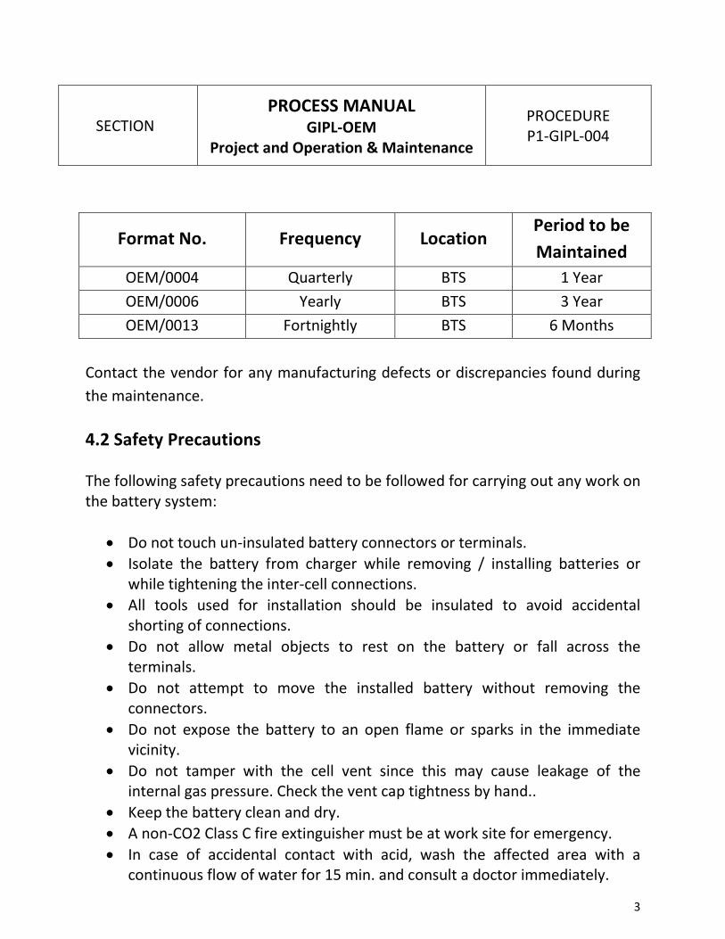
Format No. Frequency Location Period to be
Maintained
OEM/0004 Quarterly BTS 1 Year
OEM/0006 Yearly BTS 3 Year
OEM/0013 Fortnightly BTS 6 Months
Contact the vendor for any manufacturing defects or discrepancies found during
the maintenance.
4.2 Safety Precautions
The following safety precautions need to be followed for carrying out any work on
the battery system:
• Do not touch un-insulated battery connectors or terminals.
• Isolate the battery from charger while removing / installing batteries or
while tightening the inter-cell connections.
• All tools used for installation should be insulated to avoid accidental
shorting of connections.
• Do not allow metal objects to rest on the battery or fall across the
terminals.
• Do not attempt to move the installed battery without removing the
connectors.
• Do not expose the battery to an open flame or sparks in the immediate
vicinity.
• Do not tamper with the cell vent since this may cause leakage of the
internal gas pressure. Check the vent cap tightness by hand..
• Keep the battery clean and dry.
• A non-CO2 Class C fire extinguisher must be at work site for emergency.
• In case of accidental contact with acid, wash the affected area with a
continuous flow of water for 15 min. and consult a doctor immediately.
4
SECTION
PROCESS MANUAL GIPL-OEM
Project and Operation & Maintenance
PROCEDURE
P1-GIPL-004
• Inform and take permit from concerned authorities for the work. In case of
BTS/FSR/OR/MWR sites, only inform the concerned authorities and no
work permit is required.
• Use a suitable lifting device in handling the battery to prevent damage.
4.3 Tools Required
• Calibrated Digital Multimeter
• Insulated Spanners
• Torque Wrench (Insulated)
• Cloth, Cotton rags
• Nylon Brush
• Eye goggles for VRLA and face shield for flooded cells.
• Rubber Gloves
• Infra Red Temperature Scanner (optional) or normal temperature
indicator(shall be organised if required)
• D.C. Clamp Meter for current reading
• Protective Clothing
• First aid kit
5.1 Purpose of Inspection
The purpose of the fortnightly inspection is to visually check the general
conditions of the battery & battery area including condition-monitoring check of
its various parameters. The following types of problems can be detected during
the fortnightly inspection:
• Loose connections of the battery
• Electrolyte leakage from pressure relief valve, cracked container, or post
seal.
• Improper float voltage
• Abnormal battery area ambient temperature (high temperature can reduce
battery life and contribute to dry out)

5
SECTION
PROCESS MANUAL GIPL-OEM
Project and Operation & Maintenance
PROCEDURE
P1-GIPL-004
• Improper operation of the battery area ventilation system
5.2 Inspection Procedure
NOTE: Whenever performing maintenance inspections, ensure that the
manufacturer's instruction manuals for the battery and charger are available for review.
• Verify that the battery area safety equipment is available and operational.
This includes the eye wash device in first aid box and fire extinguisher, as
applicable.
• Verify that personal safety equipment is available and in good condition.
This includes goggles, face shields, plastic or rubber aprons, and gloves.
• Verify that battery cleaning and acid neutralization supplies are available.
Baking soda, water, a nonconductive container for mixing, and wiping
cloths are recommended.
• Visually inspect the battery area for cleanliness. Assure that the area is dry
and clear of debris.
CAUTION: Use only clean water for cleaning battery component.
Solvents and greases can damage cell containers. Follow the
manufacturer’s instruction closely to avoid damage to battery.
• Visually inspect all cell jars or battery modules, and the battery rack for
cleanliness and any signs of distortion or damage.
• Measure and record the battery area ambient temperature. The desired
temperature should be in the range of 21°C (70°F) to 27°C (80°F).
NOTES:
If the battery is located in an enclosure, the ambient temperature should be
measured inside the enclosure, not in the surrounding area.
Extended operation at a high temperature shortens battery life. In general, VRLA
battery life is reduced by at least 50% for every 8.3°C (15°F) of continuous
6
SECTION
PROCESS MANUAL GIPL-OEM
Project and Operation & Maintenance
PROCEDURE
P1-GIPL-004
operation above 25°C (77°F). At very high temperatures, VRLA batteries are also
more susceptible to other failure modes such as dry out or thermal runaway.
If a battery is normally maintained at a temperature significantly different than
25°C (77°F), verify that the float voltage is set in accordance with the
manufacturer’s recommendations. The float voltage shall be reduced by 3 mV per
degree centigrade rise of temperature above 27 oC. This is as per
recommendations of HBL Nife mentioned in the O&M manual.
• Verify that the cells have protective covers in place to minimize short circuit
safety hazards.
• Verify that the voltmeter calibration has not expired. Use a calibrated
voltmeter with an accuracy of at least 0.5% of the measured voltage.
• Assure that the voltmeter test leads are well insulated and securely
attached to the meter to prevent their falling onto a cell and causing a
short circuit.
• Inspect the entire rack for any loose connections or broken parts.
• Visually inspect for missing or broken seismic rack parts / spacers.
• Check that the jar and post seals are not broken. Consult with the
manufacturer if post seal failure is suspected.
• Check the jars / cover for excessive distortion.
• Check the vent cap tightness by hand.
• Check for any signs of vibration.
• Visually check for cracks or signs of electrolyte leakage in each cell. Check
for signs of electrolyte leakage from the pressure relief valve and battery
terminal poles of each cell. Inspect the flooring below the cells for
symptoms of past leakage. If electrolyte leakage is observed, contact the
manufacturer to determine if the cells require replacement. Electrolyte
leakage can cause a loss of capacity and can lead to other VRLA failure
modes.
• Visually inspect the cell posts for corrosion and damage. Corrosion on the
cell posts can indicate a loss of post seal integrity, which can result in rapid
dry out and failure of a VRLA battery. Wipe off any signs of corrosion from

7
SECTION
PROCESS MANUAL GIPL-OEM
Project and Operation & Maintenance
PROCEDURE
P1-GIPL-004
the posts. Re-grease the post with anticorrosion petroleum jelly if
necessary.
CAUTION: Because float voltages are accurate cell indicators only when taken on
a fully charged battery, be sure that at least 72 hours have elapsed since the
system was discharged or equalized.
• Record the charger output voltage and current. Verify that the output
voltage is within the desired range. This shall be 54.5 V + 0.2 V DC for 48 V
system including cable drop.
CAUTION: Observe the proper polarity when taking voltage measurements to
avoid positive and negative calibration differences in the voltmeter.
• Measure and record the voltage at the battery terminals. Divide this
measurement by the number of cells in the battery to confirm that the
average individual cell voltage is within the range recommended by the
manufacturer.
Float voltage for:
2V battery cell = 2.25 V + 0.03 V DC at 27 °C.
12V battery cell = 13.5V + 0.03V DC at 27 °C
• If float voltage is outside the recommended range, adjust the charger
output to the recommended value in accordance with facility procedures.
4.6 Quarterly Inspection
4.6.1 Purpose of Inspection
The quarterly inspection provides confirmation that the battery and individual
cells are being maintained within recommended operating limits. Also, the
quarterly inspection for a VRLA battery is intended to confirm that excessive
internal battery degradation has not occurred.
8
SECTION
PROCESS MANUAL GIPL-OEM
Project and Operation & Maintenance
PROCEDURE
P1-GIPL-004
The following checks are specified on a quarterly basis:
• Fortnightly, inspection as described in Section 4.4, except the float voltage
checks are performed on all cells.
• Short term discharge test or Continuity Test to examine individual cell
conditions when individual cell readings are beyond limits.
4.6.2 Inspection Procedure
Refer Format No.: OEM/0004 for quarterly maintenance of VRLA battery.
• Perform the fortnightly inspection as specified in 4.4
• Inspect all cables connected to the battery. Check for any
overheating/looseness.
• Tighten all inter-cell connections using a torque wrench. Do not apply more
than 10 Nm torque.
• Check the vent cap tightness by hand.
• Measure and record each cell float voltage. Compare the cell voltages to
the range recommended by the manufacturer. Ensure that the voltage
readings are within the tolerance specified by the manufacturer for the
particular battery. If any individual cell measurement exceeds the
manufacturer’s recommended tolerance, investigate for abnormal
conditions. Record the results in the format as shown in Format No.:
OEM/0007.
• With proper float operation at recommended voltages, individual cell
voltages should be within + 0.03 volts of the average cell voltage. This is
generally between 2.25 V DC + 0.03 V DC for 2V battery cells and 13.5 V DC
+ 0.03 V DC for 12V battery cell at 27 0C.
• When the voltages of individual cells are lower than normal, it is possible to
conclude that insufficient charging has occurred.
• If the individual cell voltages are beyond the range mentioned above i.e.
less than 2.20V DC and more than 2.30V DC then proceed with the
continuity test as per the following procedure 3.2.5.4.6.3 to find out weak
cells in the bank.

9
SECTION
PROCESS MANUAL GIPL-OEM
Project and Operation & Maintenance
PROCEDURE
P1-GIPL-004
• Measure the battery ICC joints temperature and the bus bar joint
temperature. If the temperature is above 50 0C or the temperatures are
unequal then terminate the battery discharge test. Check the bus-bar joints
for loose connections. Tighten the connections and continue the battery
discharge test.
Battery discharge test using SMPS parameters:
Short term discharge test and annual discharge test methods are explained in the
subsequent paragraphs. The discharge tests, wherever possible, shall be done
using the SMPS parameters.
4.6.3 Short Term Discharge test or Continuity test
Follow the steps given in the Guidelines for battery discharge test through SMPS.
Refer Format No.: OEM/0005 for short discharge test activities. The following
precautions need to be followed before this test:
• Ensure that the DG set is available and healthy by taking a trial run. If DG
set is not available, take adequate precautions.
• Inform OMCR Shift Head before conducting the test.
• Enter parameters like battery test duration, Guard time, Discharge Ah
capacity and test end voltage in SMPS parameter, whichever is applicable
(One time activity).
• Select Start battery discharge test form SMPS.
• The SMPS shall lower the output voltage of rectifier to the battery test
voltage. This allows the battery bank to discharge through the connected
load.
• Determine the durations of the test based on the battery AH capacity and
the load current. Refer the following section for deciding the duration of
the test. Enter the value in SMPS parameter.
10
SECTION
PROCESS MANUAL GIPL-OEM
Project and Operation & Maintenance
PROCEDURE
P1-GIPL-004
• The batteries have to be continuously monitored for rise in temp. & for
weak cell.
• Since the batteries are discharged for nearly 20% capacity it must be
ensured that the batteries are fully charged after the test. The SMPS should
change over to automatic boost mode and should stay in boost for 16
hours. It is advised to start the DG set and charge the batteries.
4.6.3.1 Determining the duration of the Short term Discharge test
Refer Format No.: OEM/0005 for the discharge duration of HBL Nife batteries for
an end cell voltage of 1.85V DC for 2V battery. Based on the total load and the
battery’s rated capability, determine how long to conduct the continuity test; it is
not intended that a continuity test fully discharge the battery. The battery should
have greater than 80% of its original capacity when the test is complete. Also,
determine the minimum allowed DC voltage and establish test termination
criteria above this minimum voltage. For example a site with 320AH batteries and
a load of 55A the test duration can be calculated as follows:
Duration in minutes = AH capacity x 60 min x 0.2 / 55A
The duration works out to approximately 70 minutes. “0.2” in the above formula
represents the AH capacity to be discharged. We can deduce from the table that
for a load of 55A the total discharge time available is 5 hours. In a similar fashion
we can calculate the duration for other rating battery banks.
To initiate the battery discharge test, refer the guidelines for battery discharge
test through SMPS. The individual cell voltages and entire bank voltage shall be
recorded at every 15 minutes interval on the format mentioned in Format No.:
OEM/0007.
The test shall be terminated if the bank voltage falls below the limit of 45.6 V DC,
or if any of the individual cell voltage falls below 1.90 V DC. Terminate the test
also when the battery ICC joints temperature or the bus bar joint temperature is
above 50 0C or the temperatures are unequal. Check the bus-bar joints for loose
connections. Tighten the connections and continue the battery discharge test.

11
SECTION
PROCESS MANUAL GIPL-OEM
Project and Operation & Maintenance
PROCEDURE
P1-GIPL-004
4.6.3.2 Corrective Actions
The following corrective actions need to be taken after the test and evaluation of
results:
• Mark the individual cells that have reached a voltage of 1.90 V and equalize
charge the battery for revival of battery cell. If cell is not picking up after
equalising charge also then arrange for replacement.
• If the entire battery bank voltage falls below 45.6 V DC within the set
duration then consult manufacturer for an equalisation of the bank and a
Capacity Discharge test.
5.4.7 Annual Discharge (Capacity) Test A capacity discharge test determines the extent to which a battery is capable of
supplying the manufacturer’s rated discharge current for a given duration under a
specific set of conditions. It is designed to allow trending of the battery’s capacity
by discharging the battery at a constant current or power to a predefined
endpoint voltage and comparing the actual discharge time to the manufacturer’s
rated discharge time. As per IEEE 1188 this test should be conducted once a year.
The annual discharge test for batteries of BTS does not need a planned event (PE).
Similarly there are two battery banks in IS and hence we do not need a PE. Also
the battery backup of the IS station is more than 4 to 5 hours. Hence it is ideal to
carry out the discharge test using external load for individual banks. However the
batteries of MCN have to be discharged under a PE window. Follow the steps
given in the Guidelines for battery discharge test through SMPS.
5.4.7.1 Initial Conditions before the test
• Ensure that the battery bank is fully charged for at least 48 hours prior to
the test. If the SEB supply is unreliable then it is recommended to carry out
the charging using the site DG set.
• Measure and record the float voltage of each cell just prior to the test.
• Measure and record the cell temperature of 10% or more of the cells just
prior to the test to establish an average temperature.
12
SECTION
PROCESS MANUAL GIPL-OEM
Project and Operation & Maintenance
PROCEDURE
P1-GIPL-004
• Measure and record the battery terminal float voltage.
5.4.7.2 Precautions before the test
• Ensure that the DG set available at site is healthy by conducting a manual
trial. If DG set is not available, take adequate precautions.
• Inform NOC/OMC desk before conducting the test.
• Determine the durations of the test based on the battery AH capacity and
the load current. Refer the following section for deciding the duration of
the test.
• The batteries have to be continuously monitored to ensure that a loss of
power does not occur.
• Since the batteries are discharged for nearly 90% capacity it must be
ensured that the batteries are fully charged after the test. If necessary the
DG set can be put into service for charging of batteries.
5.4.7.3 Methodology for the discharge test
Refer Format No.: OEM/0006 for carrying out annual discharge test of VRLA
battery. The discharge test can be carried out either with the site load or by using
an external resistive load bank. This decision will be based on the site load. If the
site load is more than the 3-hours discharge rate of the battery bank then the test
has to be done using the site load and no external load is required.
However if the site load is less than 3-hours discharge rate then it is
recommended to use an external load bank of suitable rating. The rating of the
load bank must be at least 20% of the battery AH capacity. For example for a
battery bank of 320AH, the load bank must be suitable for a continuous rating of
64A. The following sections elaborate the procedure for both these methods.
5.4.7.4 Annual Discharge test using site load
• Ensure that all safety precautions are strictly followed.
• Note down the site load current and the battery float voltage.
13
SECTION
PROCESS MANUAL GIPL-OEM
Project and Operation & Maintenance
PROCEDURE
P1-GIPL-004
• Measure the individual cell voltages and record the same on the format as
shown in Format No.: OEM/0007.
• Refer the battery table of HBL Nife mentioned in Format No.: OEM/008 and
decide the time duration corresponding to the site load current.
• Enter parameters like battery test duration, Guard time, Discharge Ah
capacity and test end voltage in SMPS parameter, whichever is applicable.
• Select Start battery discharge test form SMPS.
• The SMPS shall lower the output voltage of rectifier to the battery test
voltage. This allows the battery bank to discharge through the connected
load.
• Note down the individual cell voltages, entire bank voltage, battery ICC
joints temperature and the bus-bar joint temperature at an interval of 15
minutes.
• Terminate the test when the battery terminal voltage decreases to the
calculated end voltage (44.4 V DC) or if any individual cell reaches a voltage
of 1.85 V for 2V battery. Record the time taken to reach this voltage.
• Recharge the battery in accordance with the manufacturer’s instructions
and restore it to normal standby service.
• Check the time of back up as against the design from the table in Format
No.: OEM/008. Replacement of battery bank is warranted if the time is less
than 70% of the design time.
• Mark the cells that have reached the voltage of 1.80 before the duration.
These cells need separate equalisation or replacement.
• Subsequent discharge test of the site can be taken up after equalisation or
after replacement to ensure the backup time.
• If at all it is decided to continue the test then the weak cell will have to be
removed from the bank and the test to be done with external load.
• Terminate the test also when the battery ICC joints temperature or the bus
bar joint temperature is above 50 °C or the temperatures are unequal.
Check the bus-bar joints for loose connections. Tighten the connections and
continue the battery discharge test.

14
SECTION
PROCESS MANUAL GIPL-OEM
Project and Operation & Maintenance
PROCEDURE
P1-GIPL-004
• The above step can be carried out only after the SMPS has been switched
ON and the DG back up is continuously available.
5.4.7.4 Annual Discharge test using external load (as & when
applicable)
Note: In this process there will be no battery backup for the site and hence it is
strictly recommended that the DG set is started and the SMPS is switched over to
the DG set power supply. In case of sites without DG sets, then DG set need not be
hired. Adequate precautions should be taken to conduct the discharge test.
• Ensure that all safety precautions are strictly followed.
• Note down the site load current and the battery float voltage.
• Inform OMC desk about the test and the duration.
• Start the DG set and ensure that the SMPS is performing satisfactorily on
DG set. . If DG set is not available, take adequate precautions.
• Measure the individual cell voltages and record the same on the format of
Format No.: OEM/0007.
• Disconnect the battery bank by removing the negative fuse using the fuse
puller.
• A DC breaker of at least 1.25 times of the discharge rate has to be installed
for switching and clearing any major faults.
• Connect the external load bank to the batteries. Be careful while
connecting the batteries as it has stored energy and can result in short
circuits.
• Close the DC circuit breaker and start the test.
• Start the timer and begin the load test at the temperature-corrected test
discharge rate.
• Monitor the test current throughout the test and adjust the load bank as
needed to maintain a constant test current.
• Measure and record individual cell voltages, battery terminal voltage,
battery ICC joints temperature and the bus-bar joint temperature. Take the
readings just prior to starting the test, at the beginning of the test when
15
SECTION
PROCESS MANUAL GIPL-OEM
Project and Operation & Maintenance
PROCEDURE
P1-GIPL-004
load is first applied, at periodic intervals of 15 minutes during the test, and
at the completion of the test.
• Maintain the test discharge rate until the battery terminal voltage
decreases to the specified average end of discharge voltage per cell times
the number of cells in the battery (For 2V battery, 1.75 V x 24 = 42.40 V).
Do not continue the test below the specified voltage.
• Observe the battery during the test for intercell connector heating.
• Terminate the test when the battery terminal voltage decreases to the
calculated end voltage (42.40 VDC) or of any individual cell reaches a
voltage of (1.75V for 2V battery).
• The test can be continued after jumpering the weak cell or by removing the
cell from the bank. However it must be noted that the battery bank voltage
has now to be recalculated as no. of cells in the bank multiplied by the cut-
off cell voltage i.e. 1.75V for 2V battery
• Terminate the test also when the battery ICC joints temperature or the bus
bar joint temperature is above 50 0C or the temperatures are unequal.
Check the bus-bar joints for loose connections. Tighten the connections and
continue the battery discharge test.
• Record the total test time.
• Disconnect the test equipment.
• Recharge the battery in accordance with the manufacturer’s instructions
and restore it to normal standby service.
• Check the time of back up as against the design from the table in Format
No.: OEM/008 Replacement of battery bank is warranted if the time is less
than 70% of the design time.
The above procedure is a general guideline for the discharge test. In case of any
doubts regarding this procedure please consult the Core group or the Battery
manufacturer for clarifications.
5.4.7.5 Corrective Actions
16
SECTION
PROCESS MANUAL GIPL-OEM
Project and Operation & Maintenance
PROCEDURE
P1-GIPL-004
The following corrective actions need to be taken after evaluating the discharge
test:
• If the discharge duration is less than the set time then consult the
manufacturer.
• Based on the manufacturer’s recommendation conduct an equalisation
charge and redo the above discharge test.
• Even after the equalisation charge if the battery bank does not provide the
design back-up then replace the entire battery bank.
5.5 Replacement Criteria
1. Over the life of any backup power system, the installed battery eventually
requires replacement. When the predicted end of life for a battery is less
than 2 years away, the impending need for replacement should be
identified and budgeted. Larger battery installations should be planned as
far in advance as possible. Smaller batteries might not need as much lead-
time for evaluation.
2. Any of the following conditions can require a battery replacement:
• Capacity below, at, or approaching 70% (as determined by a capacity
test)
• Age approaching the manufacturer’s predicted service life
• Continuity test indicating low battery capacity
• Excessive number of individual cell failures such that the entire
battery should be replaced rather than individual cells
• Load growth that prevents the battery from meeting its load
requirements
• New or revised design requirements
• Severe battery degradation
3. Except for cases of sudden battery degradation, trending of battery
performance should allow maintenance personnel to predict when
replacement will be necessary.
17
SECTION
PROCESS MANUAL GIPL-OEM
Project and Operation & Maintenance
PROCEDURE
P1-GIPL-004
4. Individual cells might require replacement when a capacity test or
continuity test determines that they are degraded. Unless the battery is
nearing the end of its service life or many cells in the battery are degraded,
it is acceptable to replace individual cells within the battery. Based on
industry experience to date, it is likely that some cells will require
replacement in the first 4 years of service.
5.6 Check of Other Equipment
• For a good battery installation, a battery replacement is a relatively rare
event. The rest of the system should be inspected and upgraded, as
needed, as part of the battery replacement. While the battery is out of
service for replacement, perform the following:
• Inspect DC system breakers.
• Inspect cabling for aging or damage. Replace as necessary.
• Inspect the battery rack for damage or corrosion. Replace as
necessary.
• Replace older fuses in the DC system as a precautionary measure.
The charger should receive special attention as part of a battery
replacement.
• Complete the following:
� If the new battery has a larger capacity, confirm that the
charger size is still adequate.
� Check the voltmeter calibration at the float and equalize
voltages.
� Check for loose connections and evidence of overheating.
� Check the charger failure alarm by opening the AC breaker.
Check the setting of other voltage relays.
� Inspect contacts on relays for signs of pitting or burning.
� Evaluate the output filter capacitors and replace if necessary.
• As part of the battery replacement, make everything in the system as new
as possible, not just the battery. The other equipment also ages. If it is not

18
SECTION
PROCESS MANUAL GIPL-OEM
Project and Operation & Maintenance
PROCEDURE
P1-GIPL-004
inspected and upgraded during the battery replacement, it might be many
years before it is looked at closely again.
• The float voltage of VRLA should be 2.25 V +/- 0.03 V DC per cell for 2V
battery and 13.5 V DC + 0.03 V DC per cell for 12V battery at the battery
terminals. The SMPS output shall be suitably adjusted to incorporate the
voltage drop in the battery cable. For example, if the voltage drop is 0.4V
then the rectifier output shall be 54.5V (i.e. 2.25 x 24 + 0.5V or 13.5*4 +
0.5V).
• The SMPS used for the charging of the battery has boost charging facility.
This facility shall be enabled. The boost charge is started automatically once
the batteries have discharged more than a set value. This value is generally
kept as 6 to 10 %.
• 5. The preferred charging current for VRLA batteries is 0.1C i.e. 10 % of the
battery AH. However for sites with frequent power failures and voltage
fluctuations this can be increased up to 0.15 C.
.7 Maintenance Checks of a New Battery
1. Review all manufacturers’ recommendations for the installation and
operation of the battery. The installed location and configuration must
comply with the manufacturer’s requirements.
2. Perform the following maintenance-related tasks as part of the installation:
� Inspect all cells for damage before installation. Verify that the cells
were stored in accordance with the manufacturer’s
recommendations.
� Once the battery is installed, apply an initial charge in accordance
with the manufacturer’s recommendations.
� Torque all intercell connections in accordance with the
manufacturer’s specifications. If a micro-ohmmeter is available, take
a baseline set of intercell and termination resistance measurements.
These resistance measurements will form the basis for future
acceptance criteria.
19
SECTION
PROCESS MANUAL GIPL-OEM
Project and Operation & Maintenance
PROCEDURE
P1-GIPL-004
� A capacity test is recommended as part of the installation if the
manufacturer did not perform an acceptance test before shipment.
The purpose of this capacity test is to confirm adequate battery
capacity and to identify any failed cells. If a capacity test is not
performed, evaluate the internal ohmic measurements to ensure
that all cells are consistent. Abnormal internal ohmic measurements
might still require a capacity test to ensure that the battery is
acceptable.
5.8 Equalisation Charging of VRLA batteries
The equalisation charging of the batteries needs to be done whenever the battery
cell voltages are not equal (differ by more than + 0.03V). This can be found out
from Short term discharge test or from annual discharge test. This charging needs
to be done in consultation with the battery manufacturer. The following
precautions need to be taken before the equalisation charge:
• The battery bank has to be completely discharged up to end cell voltage i.e.
1.75 V for 2V battery. All the cells have to be discharged. Precaution has to
be exercised while doing the discharge with site loads. Continuous
monitoring of the individual cell voltage and the bank voltage has to be
ensured. The readings shall be recorded in the format used for annual
discharge test.
• Charge the battery bank with 0.1 C to 0.2 C rate current for a period of at
least 21 hours.
• Check the individual cell voltages after the charging. If the variation is more
than 0.1 V then contact the manufacturer, as the battery bank may need
replacement.
5.9 Charging current limits
The battery bank of VRLA cells must be charged using constant voltage chargers.
Charging must be carried out at a rate not exceeding 0.20 C10 amperes. For a 48V
battery bank the boost charging voltage will be 56.5 Volts and for float charging
20
SECTION
PROCESS MANUAL GIPL-OEM
Project and Operation & Maintenance
PROCEDURE
P1-GIPL-004
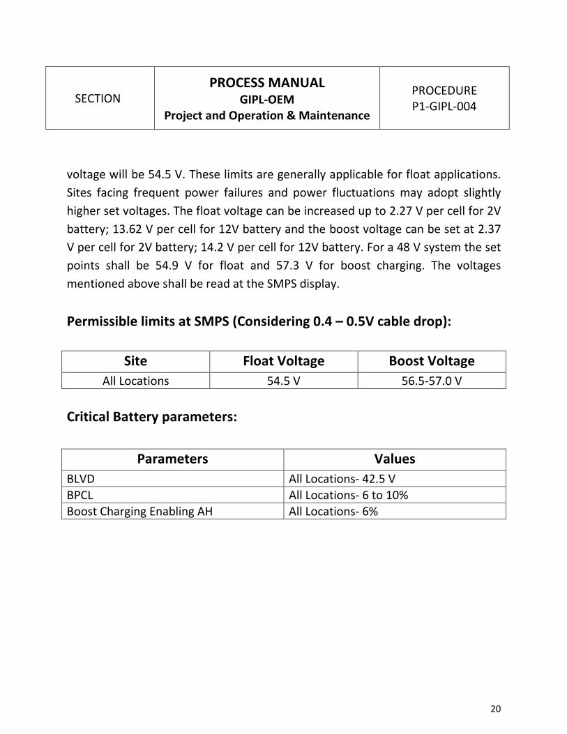
voltage will be 54.5 V. These limits are generally applicable for float applications.
Sites facing frequent power failures and power fluctuations may adopt slightly
higher set voltages. The float voltage can be increased up to 2.27 V per cell for 2V
battery; 13.62 V per cell for 12V battery and the boost voltage can be set at 2.37
V per cell for 2V battery; 14.2 V per cell for 12V battery. For a 48 V system the set
points shall be 54.9 V for float and 57.3 V for boost charging. The voltages
mentioned above shall be read at the SMPS display.
Permissible limits at SMPS (Considering 0.4 – 0.5V cable drop):
Site Float Voltage Boost Voltage
All Locations 54.5 V 56.5-57.0 V
Critical Battery parameters:
Parameters Values
BLVD All Locations- 42.5 V
BPCL All Locations- 6 to 10%
Boost Charging Enabling AH All Locations- 6%

21
SECTION
PROCESS MANUAL GIPL-OEM
Project and Operation & Maintenance
PROCEDURE
P1-GIPL-004
5.10 Formats, Records & Frequency
Format No. Description Frequency
OEM/0004 ESCS for Quarterly Maintenance of VRLA
Battery
Quarterly
OEM/0005 ESS for VRLA Battery Short Term Discharge
Test
As and when
required
OEM/0006 ESS for VRLA Battery Annual Discharge Test Annually
OEM/0007 Format to record Individual Cell Voltages of
VRLA Battery during Discharge test
As and when
required
OEM/0008 Table for Evaluating HBL Nife Battery
Discharge Duration ( only reference )
For
Information