Embed Size (px)
Citation preview
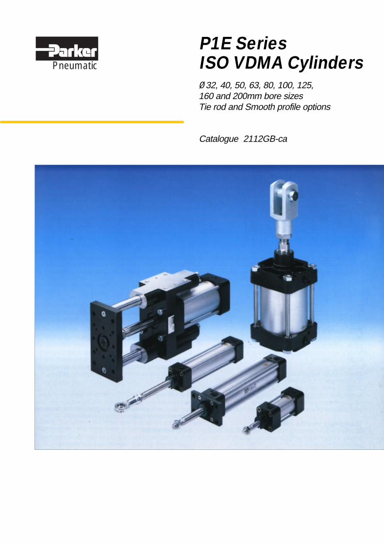
Catalogue 2112GB-ca
Ø32, 40, 50, 63, 80, 100, 125,160 and 200mm bore sizesTie rod and Smooth profile options
P1E SeriesISO VDMA CylindersPneumatic
�������������� ������
2
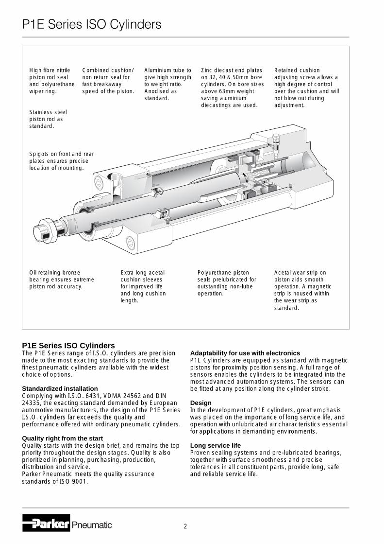
High fibre nitrile Combined cushion/ Aluminium tube to Zinc diecast end plates Retained cushionpiston rod seal non return seal for give high strength on 32, 40 & 50mm bore adjusting screw allows aand polyurethane fast breakaway to weight ratio. cylinders. On bore sizes high degree of controlwiper ring. speed of the piston. Anodised as above 63mm weight over the cushion and will
standard. saving aluminium not blow out duringdiecastings are used. adjustment.
Stainless steelpiston rod asstandard.
Spigots on front and rearplates ensures preciselocation of mounting.
Oil retaining bronze Extra long acetal Polyurethane piston Acetal wear strip onbearing ensures extreme cushion sleeves seals prelubricated for piston aids smoothpiston rod accuracy. for improved life outstanding non-lube operation. A magnetic
and long cushion operation. strip is housed withinlength. the wear strip as
standard.
P1E Series ISO CylindersThe P1E Series range of I.S.O. cylinders are precision Adaptability for use with electronicsmade to the most exacting standards to provide the P1E Cylinders are equipped as standard with magneticfinest pneumatic cylinders available with the widest pistons for proximity position sensing. A full range ofchoice of options. sensors enables the cylinders to be integrated into the
most advanced automation systems. The sensors canStandardized installation be fitted at any position along the cylinder stroke.Complying with I.S.O. 6431, VDMA 24562 and DIN24335, the exacting standard demanded by European Designautomotive manufacturers, the design of the P1E Series In the development of P1E cylinders, great emphasisI.S.O. cylinders far exceeds the quality and was placed on the importance of long service life, andperformance offered with ordinary pneumatic cylinders. operation with unlubricated air characteristics essential
for applications in demanding environments.Quality right from the startQuality starts with the design brief, and remains the top Long service lifepriority throughout the design stages. Quality is also Proven sealing systems and pre-lubricated bearings,prioritized in planning, purchasing, production, together with surface smoothness and precisedistribution and service. tolerances in all constituent parts, provide long, safeParker Pneumatic meets the quality assurance and reliable service life.standards of ISO 9001.
�������������� ������
3
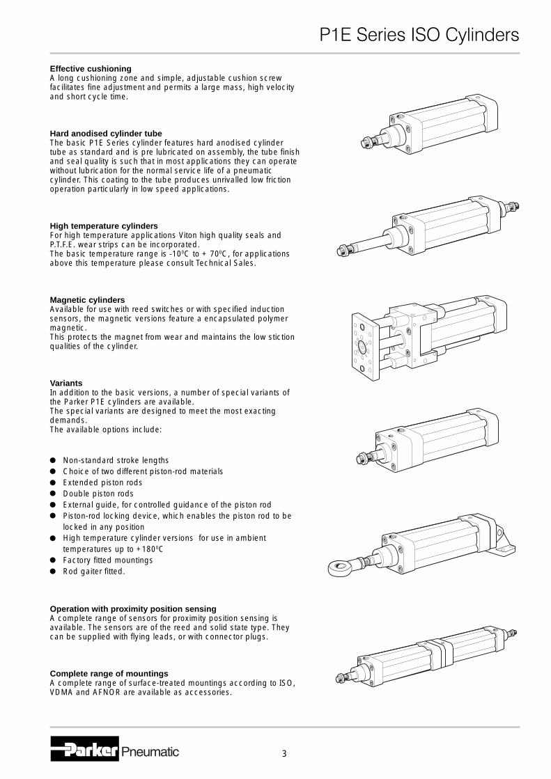
Effective cushioningA long cushioning zone and simple, adjustable cushion screwfacilitates fine adjustment and permits a large mass, high velocityand short cycle time.
Hard anodised cylinder tubeThe basic P1E Series cylinder features hard anodised cylindertube as standard and is pre lubricated on assembly, the tube finishand seal quality is such that in most applications they can operatewithout lubrication for the normal service life of a pneumaticcylinder. This coating to the tube produces unrivalled low frictionoperation particularly in low speed applications.
High temperature cylindersFor high temperature applications Viton high quality seals andP.T.F.E. wear strips can be incorporated.The basic temperature range is -100C to + 700C, for applicationsabove this temperature please consult Technical Sales.
Magnetic cylindersAvailable for use with reed switches or with specified inductionsensors, the magnetic versions feature a encapsulated polymermagnetic.This protects the magnet from wear and maintains the low stictionqualities of the cylinder.
VariantsIn addition to the basic versions, a number of special variants ofthe Parker P1E cylinders are available.The special variants are designed to meet the most exactingdemands.The available options include:
Non-standard stroke lengthsChoice of two different piston-rod materialsExtended piston rodsDouble piston rodsExternal guide, for controlled guidance of the piston rodPiston-rod locking device, which enables the piston rod to belocked in any positionHigh temperature cylinder versions for use in ambienttemperatures up to +1800CFactory fitted mountingsRod gaiter fitted.
Operation with proximity position sensingA complete range of sensors for proximity position sensing isavailable. The sensors are of the reed and solid state type. Theycan be supplied with flying leads, or with connector plugs.
Complete range of mountingsA complete range of surface-treated mountings according to ISO,VDMA and AFNOR are available as accessories.
�������������� ������
4
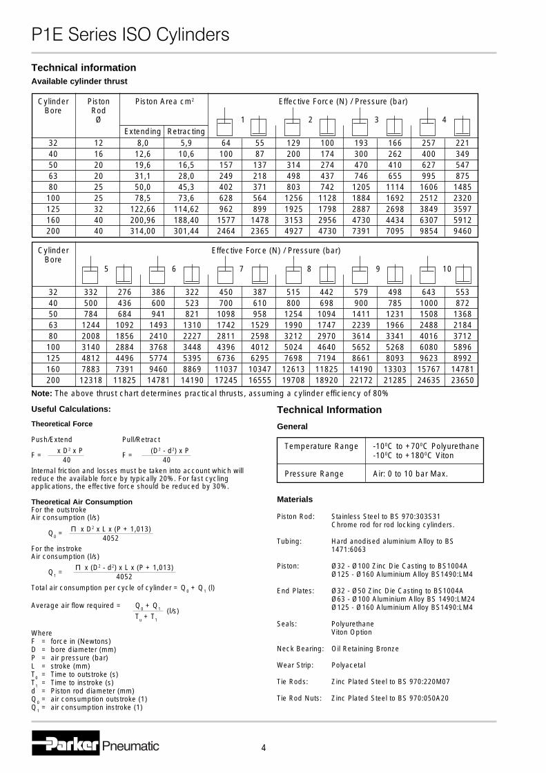
Cylinder Piston Piston Area cm2 Effective Force (N) / Pressure (bar)Bore Rod
Ø 1 2 3 4Extending Retracting
32 12 8,0 5,9 64 55 129 100 193 166 257 22140 16 12,6 10,6 100 87 200 174 300 262 400 34950 20 19,6 16,5 157 137 314 274 470 410 627 54763 20 31,1 28,0 249 218 498 437 746 655 995 87580 25 50,0 45,3 402 371 803 742 1205 1114 1606 1485
100 25 78,5 73,6 628 564 1256 1128 1884 1692 2512 2320125 32 122,66 114,62 962 899 1925 1798 2887 2698 3849 3597160 40 200,96 188,40 1577 1478 3153 2956 4730 4434 6307 5912200 40 314,00 301,44 2464 2365 4927 4730 7391 7095 9854 9460
Technical informationAvailable cylinder thrust
3240506380
100125160200
Effective Force (N) / Pressure (bar)
5 6 7 8 9 10
332 276 386 322 450 387 515 442 579 498 643 553500 436 600 523 700 610 800 698 900 785 1000 872784 684 941 821 1098 958 1254 1094 1411 1231 1508 1368
1244 1092 1493 1310 1742 1529 1990 1747 2239 1966 2488 21842008 1856 2410 2227 2811 2598 3212 2970 3614 3341 4016 37123140 2884 3768 3448 4396 4012 5024 4640 5652 5268 6080 58964812 4496 5774 5395 6736 6295 7698 7194 8661 8093 9623 89927883 7391 9460 8869 11037 10347 12613 11825 14190 13303 15767 14781
12318 11825 14781 14190 17245 16555 19708 18920 22172 21285 24635 23650
CylinderBore
Note: The above thrust chart determines practical thrusts, assuming a cylinder efficiency of 80%
Technical Information
Materials
Piston Rod: Stainless Steel to BS 970:303S31Chrome rod for rod locking cylinders.
Tubing: Hard anodised aluminium Alloy to BS1471:6063
Piston: Ø32 - Ø100 Zinc Die Casting to BS1004AØ125 - Ø160 Aluminium Alloy BS1490:LM4
End Plates: Ø32 - Ø50 Zinc Die Casting to BS1004AØ63 - Ø100 Aluminium Alloy BS 1490:LM24Ø125 - Ø160 Aluminium Alloy BS1490:LM4
Seals: PolyurethaneViton Option
Neck Bearing: Oil Retaining Bronze
Wear Strip: Polyacetal
Tie Rods: Zinc Plated Steel to BS 970:220M07
Tie Rod Nuts: Zinc Plated Steel to BS 970:050A20
Temperature Range -100C to +700C Polyurethane-100C to +1800C Viton
Pressure Range Air: 0 to 10 bar Max.
General
Useful Calculations:
Theoretical Force
Push/Extend Pull/Retract
F = F =
Internal friction and losses must be taken into account which willreduce the available force by typically 20%. For fast cyclingapplications, the effective force should be reduced by 30%.
Theoretical Air ConsumptionFor the outstrokeAir consumption (l/s)
Q0 =
For the instrokeAir consumption (l/s)
Q1 =
Total air consumption per cycle of cylinder = Q0 + Q1 (l)
Average air flow required = Q0 + Q1
Tu + T1
WhereF = force in (Newtons)D = bore diameter (mm)P = air pressure (bar)L = stroke (mm)T0 = Time to outstroke (s)T1 = Time to instroke (s)d = Piston rod diameter (mm)Q0 = air consumption outstroke (1)Q1 = air consumption instroke (1)
x D2 x P40
(D2 - d2) x P40
Π x D2 x L x (P + 1,013)4052
Π x (D2 - d2) x L x (P + 1,013)4052
(l/s)
�������������� ������
5
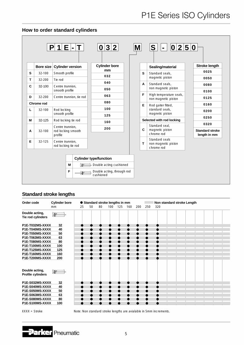
How to order standard cylinders
Cylinder boremm
032
040
050
063
080
100
125
160
200
Stroke length
0025
0050
0080
0100
0125
0160
0200
0250
0320
Standard strokelength in mm
Bore size Cylinder version
S 32-100 Smooth profile
T 32-200 Tie rod
C 32-100 Centre trunnion,smooth profile
D 32-200 Centre trunnion, tie rod
Chrome rod
L 32-100 Rod lockingsmooth profile
M 32-125 Rod locking tie rod
Centre trunnion,A 32-100 rod locking smooth
profile
E 32-125 Centre trunnion,rod locking tie rod
Sealing/material
S Standard seals,magnetic piston
A Standard seals,non magnetic piston
F High temperature seals,non magnetic piston
E Rod gaiter fitted,standard seals,magnetic piston
Selected with rod locking
Standard seal,C magnetic piston
chrome rod
Standard sealsT non magnetic piston
chrome rod
Cylinder type/function
M Double acting cushioned
F Double acting, through rodcushioned
P 1 E - T 0 3 2 M S - 0 2 5 0
Standard stroke lengths
Order code Cylinder bore Standard stroke lengths in mm Non standard stroke Lengthmm 25 50 80 100 125 160 200 250 320
Double acting,Tie rod cylinders
P1E-T032MS-XXXX 32P1E-T040MS-XXXX 40P1E-T050MS-XXXX 50P1E-T063MS-XXXX 63P1E-T080MS-XXXX 80P1E-T100MS-XXXX 100P1E-T125MS-XXXX 125P1E-T160MS-XXXX 160P1E-T200MS-XXXX 200
Double acting,Profile cylinders
P1E-S032MS-XXXX 32P1E-S040MS-XXXX 40P1E-S050MS-XXXX 50P1E-S063MS-XXXX 63P1E-S080MS-XXXX 80P1E-S100MS-XXXX 100
XXXX = Stroke Note: Non standard stroke lengths are avialable in 5mm increments.
�������������� ������
6
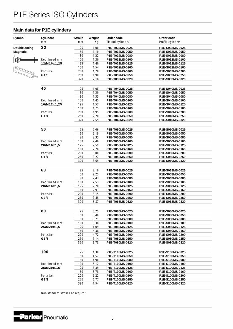
Main data for P1E cylinders
Symbol Cyl. bore Stroke Weight Order code Order codemm mm Kg Tie rod cylinders Profile cylinders
Double acting 32 25 1,00 P1E-T032MS-0025 P1E-S032MS-0025Magnetic 50 1,10 P1E-T032MS-0050 P1E-S032MS-0050
80 1,22 P1E-T032MS-0080 P1E-S032MS-0080Rod thread mm 100 1,30 P1E-T032MS-0100 P1E-S032MS-010012/M10x1,25 125 1,40 P1E-T032MS-0125 P1E-S032MS-0125
160 1,54 P1E-T032MS-0160 P1E-S032MS-0160Port size 200 1,70 P1E-T032MS-0200 P1E-S032MS-0200G1/8 250 1,90 P1E-T032MS-0250 P1E-S032MS-0250
320 2,18 P1E-T032MS-0320 P1E-S032MS-0320
40 25 1,08 P1E-T040MS-0025 P1E-S040MS-002550 1,20 P1E-T040MS-0050 P1E-S040MS-005080 1,35 P1E-T040MS-0080 P1E-S040MS-0080
Rod thread mm 100 1,45 P1E-T040MS-0100 P1E-S040MS-010016/M12x1,25 125 1,57 P1E-T040MS-0125 P1E-S040MS-0125
160 1,75 P1E-T040MS-0160 P1E-S040MS-0160Port size 200 1,95 P1E-T040MS-0200 P1E-S040MS-0200G1/4 250 2,20 P1E-T040MS-0250 P1E-S040MS-0250
320 2,59 P1E-T040MS-0320 P1E-S040MS-0320
50 25 2,06 P1E-T050MS-0025 P1E-S050MS-002550 2,19 P1E-T050MS-0050 P1E-S050MS-005080 2,35 P1E-T050MS-0080 P1E-S050MS-0080
Rod thread mm 100 2,46 P1E-T050MS-0100 P1E-S050MS-010020/M16x1,5 125 2,59 P1E-T050MS-0125 P1E-S050MS-0125
160 2,78 P1E-T050MS-0160 P1E-S050MS-0160Port size 200 3,00 P1E-T050MS-0200 P1E-S050MS-0200G1/4 250 3,27 P1E-T050MS-0250 P1E-S050MS-0250
320 3,65 P1E-T050MS-0320 P1E-S050MS-0320
63 25 2,10 P1E-T063MS-0025 P1E-S063MS-002550 2,25 P1E-T063MS-0050 P1E-S063MS-005080 2,43 P1E-T063MS-0080 P1E-S063MS-0080
Rod thread mm 100 2,53 P1E-T063MS-0100 P1E-S063MS-010020/M16x1,5 125 2,70 P1E-T063MS-0125 P1E-S063MS-0125
160 2,91 P1E-T063MS-0160 P1E-S063MS-0160Port size 200 3,15 P1E-T063MS-0200 P1E-S063MS-0200G3/8 250 3,45 P1E-T063MS-0250 P1E-S063MS-0250
320 3,87 P1E-T063MS-0320 P1E-S063MS-0320
80 25 3,25 P1E-T080MS-0025 P1E-S080MS-002550 3,46 P1E-T080MS-0050 P1E-S080MS-005080 3,71 P1E-T080MS-0080 P1E-S080MS-0080
Rod thread mm 100 3,38 P1E-T080MS-0100 P1E-S080MS-010025/M20x1,5 125 4,09 P1E-T080MS-0125 P1E-S080MS-0125
160 4,38 P1E-T080MS-0160 P1E-S080MS-0160Port size 200 4,72 P1E-T080MS-0200 P1E-S080MS-0200G3/8 250 5,14 P1E-T080MS-0250 P1E-S080MS-0250
320 5,73 P1E-T080MS-0320 P1E-S080MS-0320
100 25 4,30 P1E-T100MS-0025 P1E-S100MS-002550 4,57 P1E-T100MS-0050 P1E-S100MS-005080 4,90 P1E-T100MS-0080 P1E-S100MS-0080
Rod thread mm 100 5,12 P1E-T100MS-0100 P1E-S100MS-010025/M20x1,5 125 5,39 P1E-T100MS-0125 P1E-S100MS-0125
160 5,78 P1E-T100MS-0160 P1E-S100MS-0160Port size 200 6,22 P1E-T100MS-0200 P1E-S100MS-0200G1/2 250 6,77 P1E-T100MS-0250 P1E-S100MS-0250
320 7,54 P1E-T100MS-0320 P1E-S100MS-0320
Non standard strokes on request
�������������� ������
7
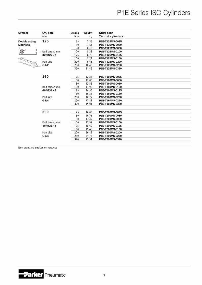
Symbol Cyl. bore Stroke Weight Order codemm mm Kg Tie rod cylinders
Double acting 125 25 7,35 P1E-T125MS-0025Magnetic 50 7,61 P1E-T125MS-0050
80 8,10 P1E-T125MS-0080Rod thread mm 100 8,38 P1E-T125MS-010032/M27x2 125 8,73 P1E-T125MS-0125
160 9,21 P1E-T125MS-0160Port size 200 9,76 P1E-T125MS-0200G1/2 250 10,45 P1E-T125MS-0250
320 11,42 P1E-T125MS-0320
160 25 12,28 P1E-T160MS-002550 12,85 P1E-T160MS-005080 13,53 P1E-T160MS-0080
Rod thread mm 100 13,99 P1E-T160MS-010040/M36x2 125 14,56 P1E-T160MS-0125
160 15,36 P1E-T160MS-0160Port size 200 16,27 P1E-T160MS-0200G3/4 250 17,41 P1E-T160MS-0250
320 19,01 P1E-T160MS-0320
200 25 16,08 P1E-T200MS-002550 16,71 P1E-T200MS-005080 17,47 P1E-T200MS-0080
Rod thread mm 100 17,97 P1E-T200MS-010040/M36x2 125 18,60 P1E-T200MS-0125
160 19,48 P1E-T200MS-0160Port size 200 20,49 P1E-T200MS-0200G3/4 250 21,75 P1E-T200MS-0250
320 23,51 P1E-T200MS-0320
Non standard strokes on request
�������������� ������
8
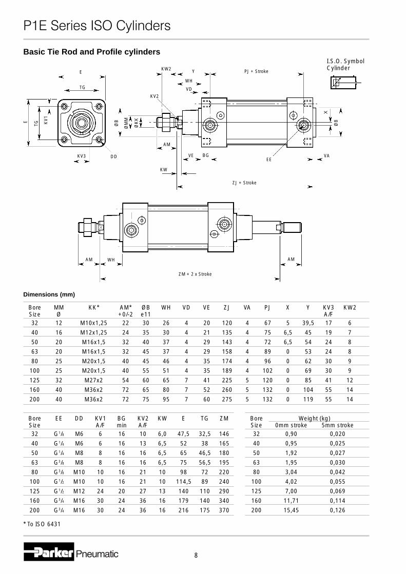
Bore MM KK* AM* ØB WH VD VE ZJ VA PJ X Y KV3 KW2Size Ø +0/-2 e11 A/F32 12 M10x1,25 22 30 26 4 20 120 4 67 5 39,5 17 6
40 16 M12x1,25 24 35 30 4 21 135 4 75 6,5 45 19 7
50 20 M16x1,5 32 40 37 4 29 143 4 72 6,5 54 24 8
63 20 M16x1,5 32 45 37 4 29 158 4 89 0 53 24 8
80 25 M20x1,5 40 45 46 4 35 174 4 96 0 62 30 9
100 25 M20x1,5 40 55 51 4 35 189 4 102 0 69 30 9
125 32 M27x2 54 60 65 7 41 225 5 120 0 85 41 12
160 40 M36x2 72 65 80 7 52 260 5 132 0 104 55 14
200 40 M36x2 72 75 95 7 60 275 5 132 0 119 55 14
Bore EE DD KV1 BG KV2 KW E TG ZMSize A/F min A/F32 G1/8 M6 6 16 10 6,0 47,5 32,5 146
40 G1/4 M6 6 16 13 6,5 52 38 165
50 G1/4 M8 8 16 16 6,5 65 46,5 180
63 G3/8 M8 8 16 16 6,5 75 56,5 195
80 G3/8 M10 10 16 21 10 98 72 220
100 G1/2 M10 10 16 21 10 114,5 89 240
125 G1/2 M12 24 20 27 13 140 110 290
160 G3/4 M16 30 24 36 16 179 140 340
200 G3/4 M16 30 24 36 16 216 175 370
Bore Weight (kg)Size 0mm stroke 5mm stroke32 0,90 0,020
40 0,95 0,025
50 1,92 0,027
63 1,95 0,030
80 3,04 0,042
100 4,02 0,055
125 7,00 0,069
160 11,71 0,114
200 15,45 0,126
Dimensions (mm)
E
TG ØK
K
ØM
M
ØB
KW
VE
Y
WH
VD
PJ + Stroke
X
ØB
EEVA
ZJ + Stroke
Basic Tie Rod and Profile cylinders
E
TG
KV2
BG
* To ISO 6431
DDKV3
KV
1
AM
KW2
AM WH AM
ZM + 2 x Stroke
I.S.O. SymbolCylinder
�������������� ������
9
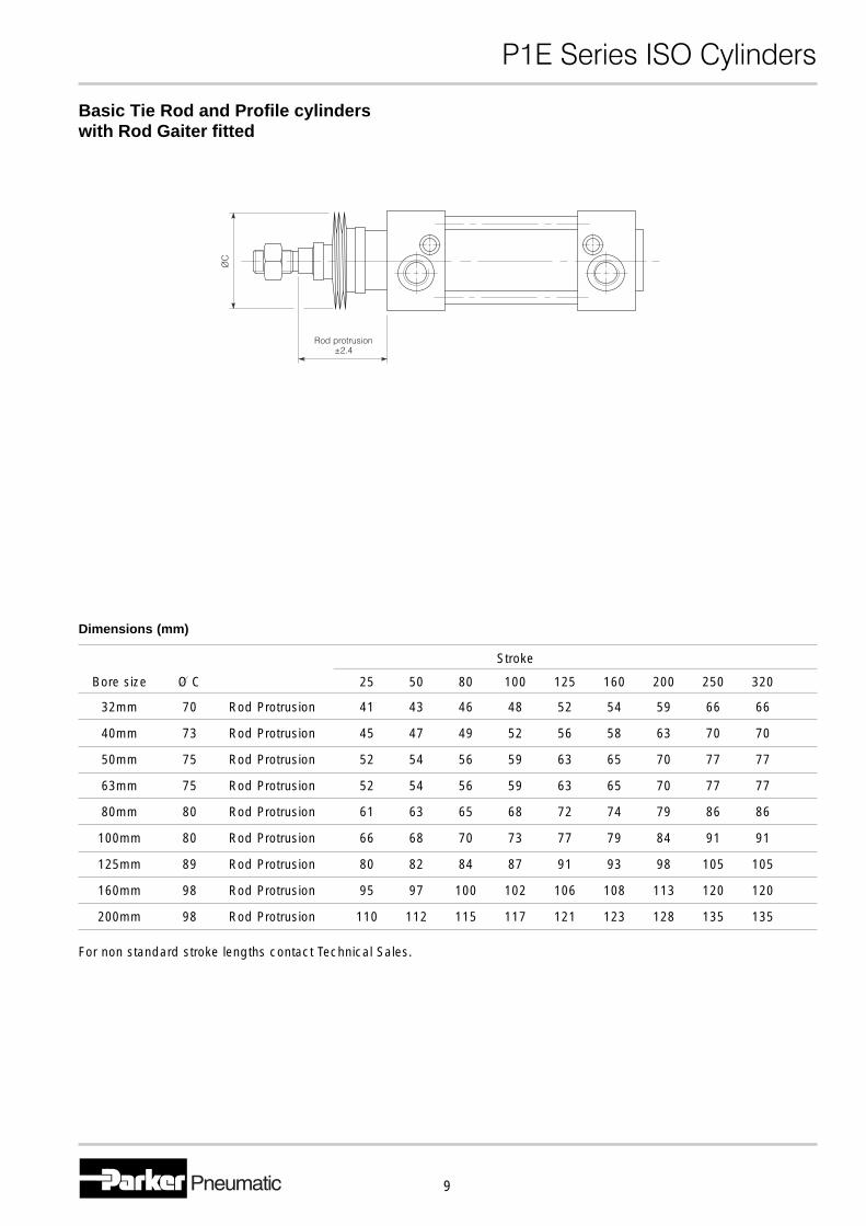
For non standard stroke lengths contact Technical Sales.
Basic Tie Rod and Profile cylinderswith Rod Gaiter fitted
Stroke
Bore size O C 25 50 80 100 125 160 200 250 320
32mm 70 Rod Protrusion 41 43 46 48 52 54 59 66 66
40mm 73 Rod Protrusion 45 47 49 52 56 58 63 70 70
50mm 75 Rod Protrusion 52 54 56 59 63 65 70 77 77
63mm 75 Rod Protrusion 52 54 56 59 63 65 70 77 77
80mm 80 Rod Protrusion 61 63 65 68 72 74 79 86 86
100mm 80 Rod Protrusion 66 68 70 73 77 79 84 91 91
125mm 89 Rod Protrusion 80 82 84 87 91 93 98 105 105
160mm 98 Rod Protrusion 95 97 100 102 106 108 113 120 120
200mm 98 Rod Protrusion 110 112 115 117 121 123 128 135 135
Dimensions (mm)
�������������� ������
10
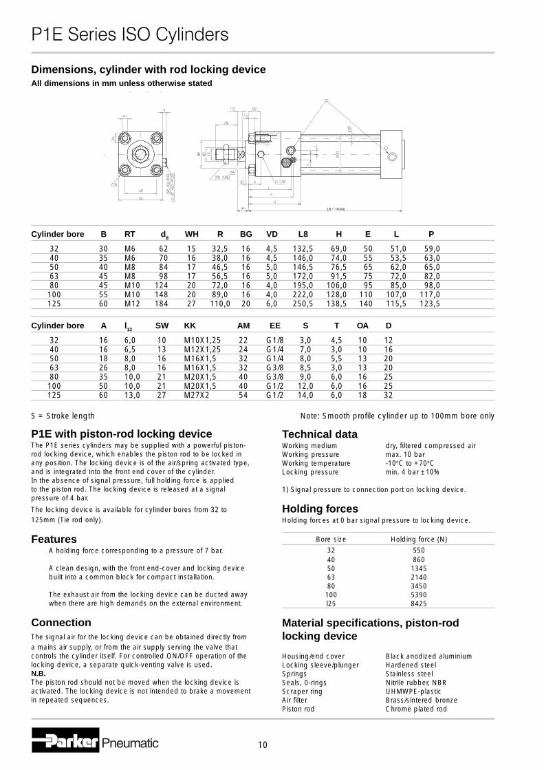
P1E with piston-rod locking deviceThe P1E series cylinders may be supplied with a powerful piston-rod locking device, which enables the piston rod to be locked inany position. The locking device is of the air/spring activated type,and is integrated into the front end cover of the cylinder.In the absence of signal pressure, full holding force is appliedto the piston rod. The locking device is released at a signalpressure of 4 bar.
The locking device is available for cylinder bores from 32 to125mm (Tie rod only).
FeaturesA holding force corresponding to a pressure of 7 bar.
A clean design, with the front end-cover and locking devicebuilt into a common block for compact installation.
The exhaust air from the locking device can be ducted awaywhen there are high demands on the external environment.
ConnectionThe signal air for the locking device can be obtained directly froma mains air supply, or from the air supply serving the valve thatcontrols the cylinder itself. For controlled ON/OFF operation of thelocking device, a separate quick-venting valve is used.N.B.The piston rod should not be moved when the locking device isactivated. The locking device is not intended to brake a movementin repeated sequences.
Cylinder bore B RT d8 WH R BG VD L8 H E L P
32 30 M6 62 15 32,5 16 4,5 132,5 69,0 50 51,0 59,040 35 M6 70 16 38,0 16 4,5 146,0 74,0 55 53,5 63,050 40 M8 84 17 46,5 16 5,0 146,5 76,5 65 62,0 65,063 45 M8 98 17 56,5 16 5,0 172,0 91,5 75 72,0 82,080 45 M10 124 20 72,0 16 4,0 195,0 106,0 95 85,0 98,0
100 55 M10 148 20 89,0 16 4,0 222,0 128,0 110 107,0 117,0125 60 M12 184 27 110,0 20 6,0 250,5 138,5 140 115,5 123,5
Cylinder bore A l12 SW KK AM EE S T OA D
32 16 6,0 10 M10X1,25 22 G1/8 3,0 4,5 10 1240 16 6,5 13 M12X1,25 24 G1/4 7,0 3,0 10 1650 18 8,0 16 M16X1,5 32 G1/4 8,0 5,5 13 2063 26 8,0 16 M16X1,5 32 G3/8 8,5 3,0 13 2080 35 10,0 21 M20X1,5 40 G3/8 9,0 6,0 16 25
100 50 10,0 21 M20X1,5 40 G1/2 12,0 6,0 16 25125 60 13,0 27 M27X2 54 G1/2 14,0 6,0 18 32
S = Stroke length Note: Smooth profile cylinder up to 100mm bore only
Dimensions, cylinder with rod locking deviceAll dimensions in mm unless otherwise stated
L8 + stroke
Technical dataWorking medium dry, filtered compressed airWorking pressure max. 10 barWorking temperature -10oC to +70oCLocking pressure min. 4 bar ±10%
1) Signal pressure to connection port on locking device.
Holding forcesHolding forces at 0 bar signal pressure to locking device.
Bore size Holding force (N)
32 55040 86050 134563 214080 3450
100 5390l25 8425
Material specifications, piston-rodlocking device
Housing/end cover Black anodized aluminiumLocking sleeve/plunger Hardened steelSprings Stainless steelSeals, 0-rings Nitrile rubber, NBRScraper ring UHMWPE-plasticAir filter Brass/sintered bronzePiston rod Chrome plated rod
�������������� ������
11
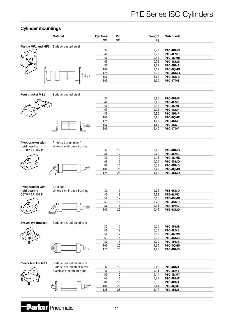
Cylinder mountings
Material Cyl. bore Pin Weight Order codemm mm Kg
Flange MF1 and MF2 Surface treated steel32 0,23 P1C-4KMB40 0,28 P1C-4LMB50 0,53 P1C-4MMB63 0,71 P1C-4NMB80 1,59 P1C-4PMB
100 2,19 P1C-4QMB125 3,78 P1C-4RMB160 6,00 P1C-4SMB200 8,00 P1C-4TMB
Foot bracket MS1 Surface treated steel32 0,06 P1C-4KMF40 0,08 P1C-4LMF50 0,16 P1C-4MMF63 0,25 P1C-4NMF80 0,50 P1C-4PMF
100 0,85 P1C-4QMF125 1,48 P1C-4RMF160 1,60 P1C-4SMF200 4,40 P1C-4TMF
Pivot bracket with Anodised aluminium/rigid bearing sintered oil-bronze bushingCETOP RP 107 P 32 10 0,06 P1C-4KMD
40 12 0,08 P1C-4LMD50 12 0,15 P1C-4MMD63 16 0,20 P1C-4NMD80 16 0,33 P1C-4PMD
100 20 0,49 P1C-4QMD125 25 1,02 P1C-4RMD
Pivot bracket with Cast iron/rigid bearing sintered oil-bronze bushing 32 10 0,06 P1E-4KMDCETOP RP 107 P 40 12 0,08 P1E-4LMD
50 12 0,15 P1E-4MMD63 16 0,20 P1E-4NMD80 16 0,33 P1E-4PMD
100 20 0,49 P1E-4QMD
Swivel eye bracket Surface treated aluminium32 10 0,20 P1C-4KMS40 12 0,30 P1C-4LMS50 12 0,50 P1C-4MMS63 16 0,70 P1C-4NMS80 16 1,20 P1C-4PMS
100 20 1,60 P1C-4QMS125 25 1,80 P1C-4RMS
Clevis bracket MP2 Surface treated aluminiumSurface treated steel screw 32 10 0,08 P1C-4KMTStainless steel treated pin 40 12 0,11 P1C-4LMT
50 12 0,14 P1C-4MMT63 16 0,29 P1C-4NMT80 16 0,36 P1C-4PMT
100 20 0,64 P1C-4QMT125 25 1,17 P1C-4RMT
�������������� ������
12
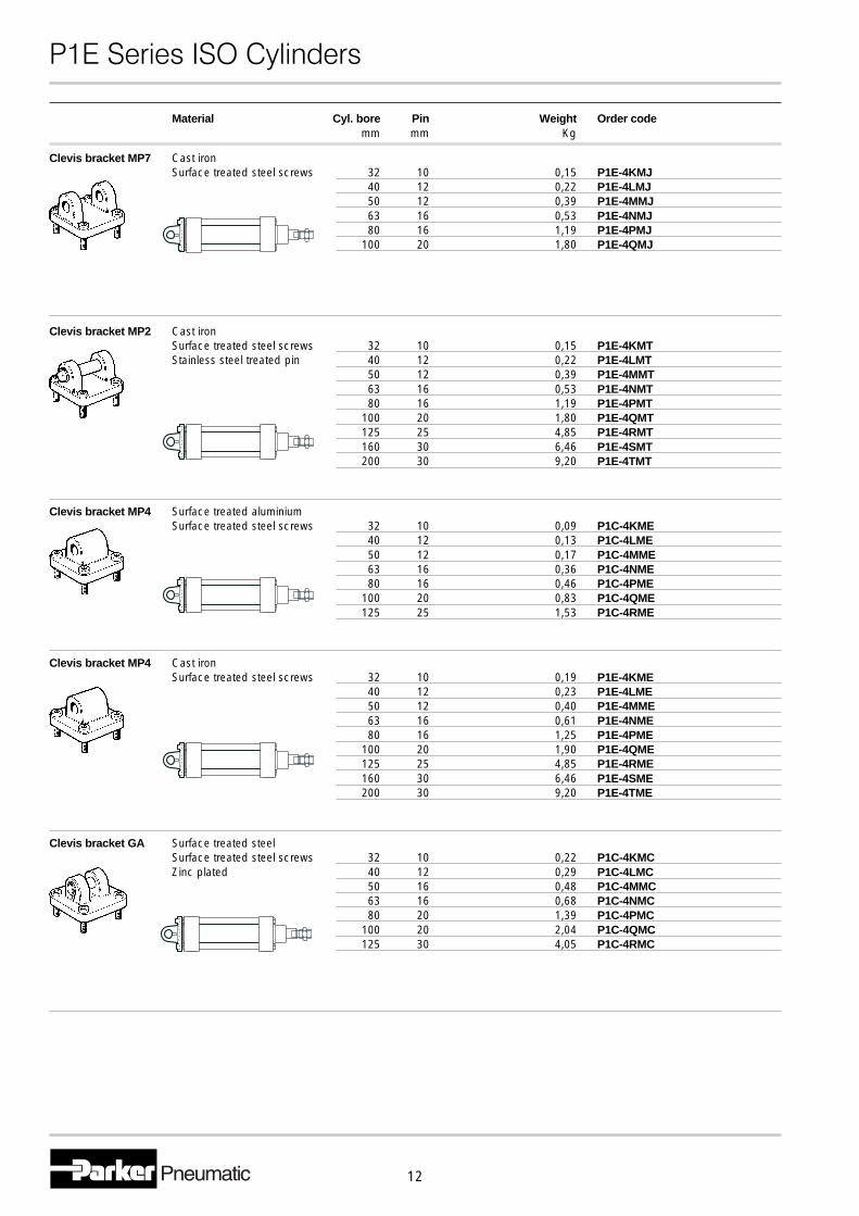
Material Cyl. bore Pin Weight Order codemm mm Kg
Clevis bracket MP7 Cast ironSurface treated steel screws 32 10 0,15 P1E-4KMJ
40 12 0,22 P1E-4LMJ50 12 0,39 P1E-4MMJ63 16 0,53 P1E-4NMJ80 16 1,19 P1E-4PMJ
100 20 1,80 P1E-4QMJ
Clevis bracket MP2 Cast ironSurface treated steel screws 32 10 0,15 P1E-4KMTStainless steel treated pin 40 12 0,22 P1E-4LMT
50 12 0,39 P1E-4MMT63 16 0,53 P1E-4NMT80 16 1,19 P1E-4PMT
100 20 1,80 P1E-4QMT125 25 4,85 P1E-4RMT160 30 6,46 P1E-4SMT200 30 9,20 P1E-4TMT
Clevis bracket MP4 Surface treated aluminiumSurface treated steel screws 32 10 0,09 P1C-4KME
40 12 0,13 P1C-4LME50 12 0,17 P1C-4MME63 16 0,36 P1C-4NME80 16 0,46 P1C-4PME
100 20 0,83 P1C-4QME125 25 1,53 P1C-4RME
Clevis bracket MP4 Cast ironSurface treated steel screws 32 10 0,19 P1E-4KME
40 12 0,23 P1E-4LME50 12 0,40 P1E-4MME63 16 0,61 P1E-4NME80 16 1,25 P1E-4PME
100 20 1,90 P1E-4QME125 25 4,85 P1E-4RME160 30 6,46 P1E-4SME200 30 9,20 P1E-4TME
Clevis bracket GA Surface treated steelSurface treated steel screws 32 10 0,22 P1C-4KMCZinc plated 40 12 0,29 P1C-4LMC
50 16 0,48 P1C-4MMC63 16 0,68 P1C-4NMC80 20 1,39 P1C-4PMC
100 20 2,04 P1C-4QMC125 30 4,05 P1C-4RMC
�������������� ������
13
Material Cyl. bore Pin Weight Order codemm mm Kg
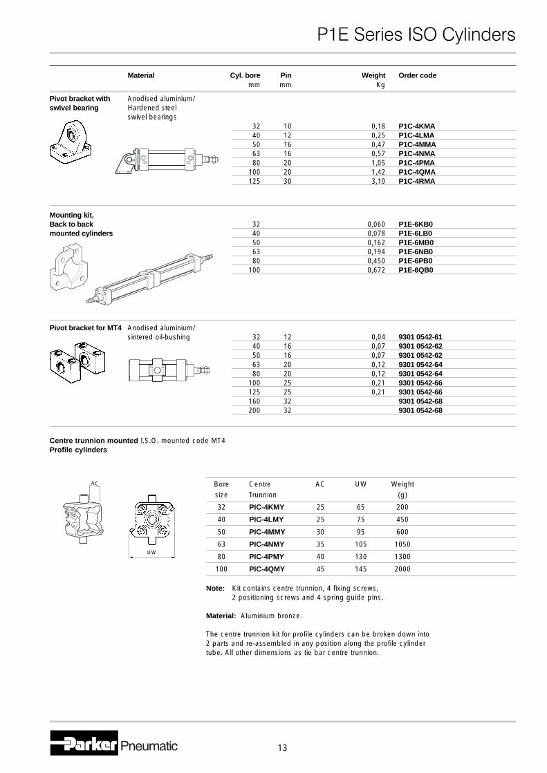
Pivot bracket with Anodised aluminium/swivel bearing Hardened steel
swivel bearings32 10 0,18 P1C-4KMA40 12 0,25 P1C-4LMA50 16 0,47 P1C-4MMA63 16 0,57 P1C-4NMA80 20 1,05 P1C-4PMA
100 20 1,42 P1C-4QMA125 30 3,10 P1C-4RMA
Mounting kit,Back to back 32 0,060 P1E-6KB0mounted cylinders 40 0,078 P1E-6LB0
50 0,162 P1E-6MB063 0,194 P1E-6NB080 0,450 P1E-6PB0
100 0,672 P1E-6QB0
Pivot bracket for MT4 Anodised aluminium/sintered oil-bushing 32 12 0,04 9301 0542-61
40 16 0,07 9301 0542-6250 16 0,07 9301 0542-6263 20 0,12 9301 0542-6480 20 0,12 9301 0542-64
100 25 0,21 9301 0542-66125 25 0,21 9301 0542-66160 32 9301 0542-68200 32 9301 0542-68
Centre trunnion mounted I.S.O. mounted code MT4Profile cylinders
Bore Centre AC UW Weightsize Trunnion (g)
32 PIC-4KMY 25 65 200
40 PIC-4LMY 25 75 450
50 PIC-4MMY 30 95 600
63 PIC-4NMY 35 105 1050
80 PIC-4PMY 40 130 1300
100 PIC-4QMY 45 145 2000
Note: Kit contains centre trunnion, 4 fixing screws,2 positioning screws and 4 spring guide pins.
Material: Aluminium bronze.
The centre trunnion kit for profile cylinders can be broken down into2 parts and re-assembled in any position along the profile cylindertube. All other dimensions as tie bar centre trunnion.
AC
UW
�������������� ������
14
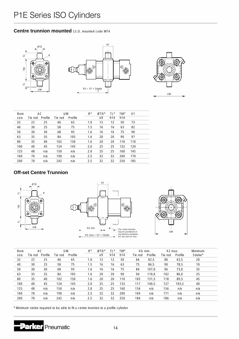
Centre trunnion mounted I.S.O. mounted code MT4
Off-set Centre Trunnion
Bore AC UW R* ØTD* TL* TM* X1size Tie rod Profile Tie rod Profile e9 h14 h1432 22 25 46 65 1.0 12 12 50 73
40 30 25 58 75 1.5 16 16 63 82
50 30 30 68 95 1.6 16 16 75 90
63 35 35 84 105 1.6 20 20 90 97
80 35 40 102 130 1.6 20 20 110 110
100 40 45 124 145 2.0 25 25 132 120
125 48 n/a 150 n/a 2.0 25 25 160 145
160 70 n/a 190 n/a 2.5 32 32 200 170200 70 n/a 242 n/a 2.5 32 32 250 185
Bore AC UW R* ØTD* TL* TM* XG min. X2 max. Minimumsize Tie rod Profile Tie rod Profile e9 h14 h14 Tie rod Profile Tie rod Profile Stroke*32 22 25 46 65 1.0 12 12 50 66 82,5 80 63,5 20
40 30 25 58 75 1.5 16 16 63 75 86,5 90 78,5 10
50 30 30 68 95 1.6 16 16 75 84 107,0 96 73,0 35
63 35 35 84 105 1.6 20 20 90 94 110,0 102 86,0 25
80 35 40 102 130 1.6 20 20 110 103 131,5 118 89,5 45100 40 45 124 145 2.0 25 25 132 117 140,5 127 103,5 40
125 48 n/a 150 n/a 2.0 25 25 160 134 n/a 156 n/a n/a
160 70 n/a 190 n/a 2.5 32 32 200 169 n/a 171 n/a n/a
200 70 n/a 242 n/a 2.5 32 32 250 184 n/a 186 n/a n/a
* Minimum stroke required to be able to fit a centre trunnion to a profile cylinder
# The centre trunnionmay be positioned atany distance betweenXG min and XG max.
XG max = X2 + Stroke
AC
UW
XG min
XG = X1 + Stroke
AC
UW2
OTD
UW
R
TLTL
TM
OTD
UW
R
TLTL
TM
�������������� ������
15
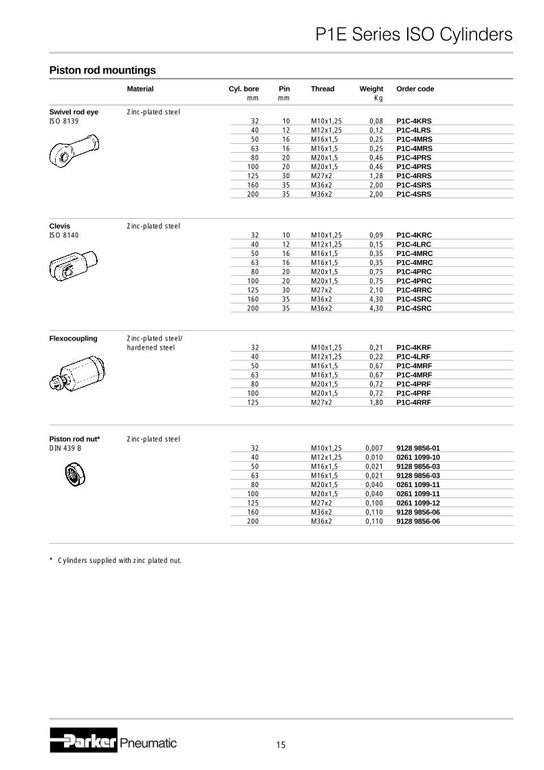
Piston rod mountings
Material Cyl. bore Pin Thread Weight Order codemm mm Kg
Swivel rod eye Zinc-plated steelISO 8139 32 10 M10x1,25 0,08 P1C-4KRS
40 12 M12x1,25 0,12 P1C-4LRS50 16 M16x1,5 0,25 P1C-4MRS63 16 M16x1,5 0,25 P1C-4MRS80 20 M20x1,5 0,46 P1C-4PRS
100 20 M20x1,5 0,46 P1C-4PRS125 30 M27x2 1,28 P1C-4RRS160 35 M36x2 2,00 P1C-4SRS200 35 M36x2 2,00 P1C-4SRS
Clevis Zinc-plated steelISO 8140 32 10 M10x1,25 0,09 P1C-4KRC
40 12 M12x1,25 0,15 P1C-4LRC50 16 M16x1,5 0,35 P1C-4MRC63 16 M16x1,5 0,35 P1C-4MRC80 20 M20x1,5 0,75 P1C-4PRC
100 20 M20x1,5 0,75 P1C-4PRC125 30 M27x2 2,10 P1C-4RRC160 35 M36x2 4,30 P1C-4SRC200 35 M36x2 4,30 P1C-4SRC
Flexocoupling Zinc-plated steel/hardened steel 32 M10x1,25 0,21 P1C-4KRF
40 M12x1,25 0,22 P1C-4LRF50 M16x1,5 0,67 P1C-4MRF63 M16x1,5 0,67 P1C-4MRF80 M20x1,5 0,72 P1C-4PRF
100 M20x1,5 0,72 P1C-4PRF125 M27x2 1,80 P1C-4RRF
Piston rod nut* Zinc-plated steelDIN 439 B 32 M10x1,25 0,007 9128 9856-01
40 M12x1,25 0,010 0261 1099-1050 M16x1,5 0,021 9128 9856-0363 M16x1,5 0,021 9128 9856-0380 M20x1,5 0,040 0261 1099-11
100 M20x1,5 0,040 0261 1099-11125 M27x2 0,100 0261 1099-12160 M36x2 0,110 9128 9856-06200 M36x2 0,110 9128 9856-06
* Cylinders supplied with zinc plated nut.
�������������� ������
16
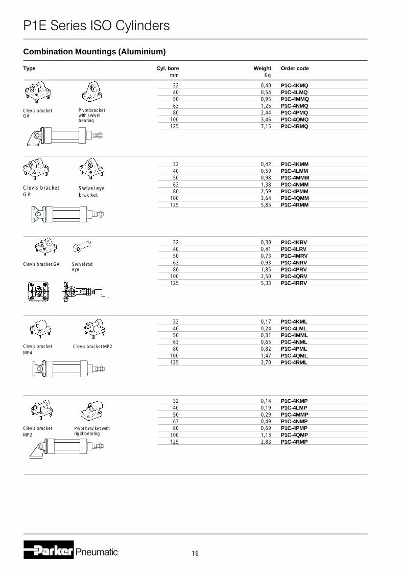
32 0,30 P1C-4KRV40 0,41 P1C-4LRV50 0,73 P1C-4MRV63 0,93 P1C-4NRV80 1,85 P1C-4PRV
100 2,50 P1C-4QRV125 5,33 P1C-4RRV
32 0,17 P1C-4KML40 0,24 P1C-4LML50 0,31 P1C-4MML63 0,65 P1C-4NML80 0,82 P1C-4PML
100 1,47 P1C-4QML125 2,70 P1C-4RML
32 0,14 P1C-4KMP40 0,19 P1C-4LMP50 0,29 P1C-4MMP63 0,49 P1C-4NMP80 0,69 P1C-4PMP
100 1,13 P1C-4QMP125 2,83 P1C-4RMP
Clevis bracket MP2Clevis bracketMP4
Clevis bracketMP2
Pivot bracket withrigid bearing
Clevis bracket GA Swivel rodeye
Clevis bracketGA
Pivot bracketwith swivelbearing
Type Cyl. bore Weight Order codemm Kg
32 0,40 P1C-4KMQ40 0,54 P1C-4LMQ50 0,95 P1C-4MMQ63 1,25 P1C-4NMQ80 2,44 P1C-4PMQ
100 3,46 P1C-4QMQ125 7,15 P1C-4RMQ
32 0,42 P1C-4KMM40 0,59 P1C-4LMM50 0,98 P1C-4MMM63 1,38 P1C-4NMM80 2,59 P1C-4PMM
100 3,64 P1C-4QMM125 5,85 P1C-4RMM
Clevis bracketGA
Swivel eyebracket
Combination Mountings (Aluminium)
�������������� ������
17
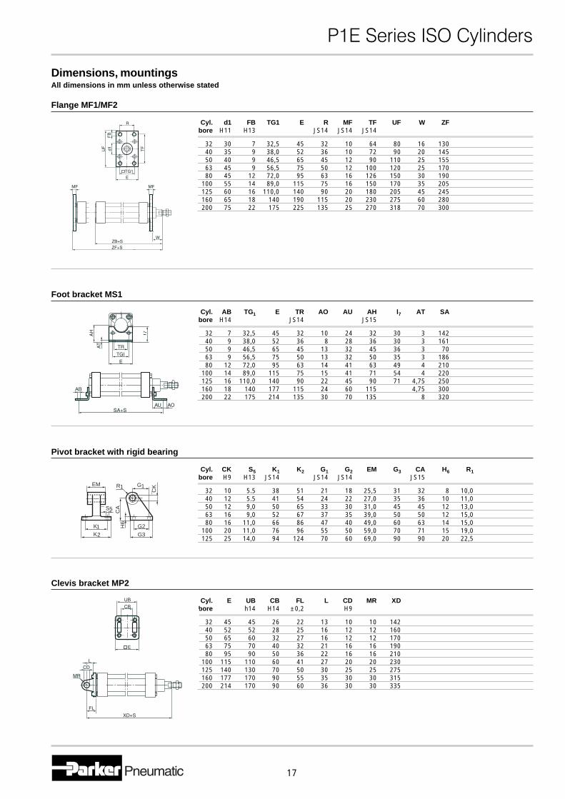
Dimensions, mountingsAll dimensions in mm unless otherwise stated
Flange MF1/MF2
Cyl. d1 FB TG1 E R MF TF UF W ZFbore H11 H13 JS14 JS14 JS14
32 30 7 32,5 45 32 10 64 80 16 13040 35 9 38,0 52 36 10 72 90 20 14550 40 9 46,5 65 45 12 90 110 25 15563 45 9 56,5 75 50 12 100 120 25 17080 45 12 72,0 95 63 16 126 150 30 190
100 55 14 89,0 115 75 16 150 170 35 205125 60 16 110,0 140 90 20 180 205 45 245160 65 18 140 190 115 20 230 275 60 280200 75 22 175 225 135 25 270 318 70 300
Foot bracket MS1
Cyl. AB TG1 E TR AO AU AH l7 AT SAbore H14 JS14 JS15
32 7 32,5 45 32 10 24 32 30 3 14240 9 38,0 52 36 8 28 36 30 3 16150 9 46,5 65 45 13 32 45 36 3 7063 9 56,5 75 50 13 32 50 35 3 18680 12 72,0 95 63 14 41 63 49 4 210
100 14 89,0 115 75 15 41 71 54 4 220125 16 110,0 140 90 22 45 90 71 4,75 250160 18 140 177 115 24 60 115 4,75 300200 22 175 214 135 30 70 135 8 320
Pivot bracket with rigid bearing
Cyl. CK S5 K1 K2 G1 G2 EM G3 CA H6 R1bore H9 H13 JS14 JS14 JS14 JS15
32 10 5.5 38 51 21 18 25,5 31 32 8 10,040 12 5.5 41 54 24 22 27,0 35 36 10 11,050 12 9,0 50 65 33 30 31,0 45 45 12 13,063 16 9,0 52 67 37 35 39,0 50 50 12 15,080 16 11,0 66 86 47 40 49,0 60 63 14 15,0
100 20 11,0 76 96 55 50 59,0 70 71 15 19,0125 25 14,0 94 124 70 60 69,0 90 90 20 22,5
Clevis bracket MP2
Cyl. E UB CB FL L CD MR XDbore h14 H14 ±0,2 H9
32 45 45 26 22 13 10 10 14240 52 52 28 25 16 12 12 16050 65 60 32 27 16 12 12 17063 75 70 40 32 21 16 16 19080 95 90 50 36 22 16 16 210
100 115 110 60 41 27 20 20 230125 140 130 70 50 30 25 25 275160 177 170 90 55 35 30 30 315200 214 170 90 60 36 30 30 335
5
G
¯CK
CA
G2
G3
1R1
H6
KK12
S¯
EM
�������������� ������
18
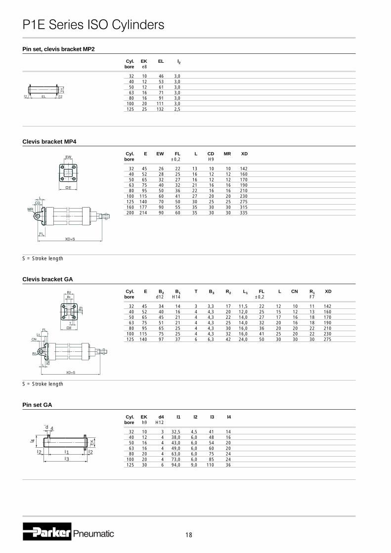
Clevis bracket MP4
Cyl. E EW FL L CD MR XDbore ±0,2 H9
32 45 26 22 13 10 10 14240 52 28 25 16 12 12 16050 65 32 27 16 12 12 17063 75 40 32 21 16 16 19080 95 50 36 22 16 16 210
100 115 60 41 27 20 20 230125 140 70 50 30 25 25 275160 177 90 55 35 30 30 315200 214 90 60 35 30 30 335
S = Stroke length
Clevis bracket GA
Cyl. E B2 B1 T B3 R2 L1 FL L CN R1 XDbore d12 H14 ±0,2 F7
32 45 34 14 3 3,3 17 11,5 22 12 10 11 14240 52 40 16 4 4,3 20 12,0 25 15 12 13 16050 65 45 21 4 4,3 22 14,0 27 17 16 18 17063 75 51 21 4 4,3 25 14,0 32 20 16 18 19080 95 65 25 4 4,3 30 16,0 36 20 20 22 210
100 115 75 25 4 4,3 32 16,0 41 25 20 22 230125 140 97 37 6 6,3 42 24,0 50 30 30 30 275
S = Stroke length
Pin set GA
Cyl. EK d4 l1 l2 l3 l4bore h9 H12
32 10 3 32,5 4,5 41 1440 12 4 38,0 6,0 48 1650 16 4 43,0 6,0 54 2063 16 4 49,0 6,0 60 2080 20 4 63,0 6,0 75 24
100 20 4 73,0 6,0 85 24125 30 6 94,0 9,0 110 36
¯EK
I2I2
¯d 4
I3
I1
l 4
Pin set, clevis bracket MP2
Cyl. EK EL l2bore e8
32 10 46 3,040 12 53 3,050 12 61 3,063 16 71 3,080 16 91 3,0
100 20 111 3,0125 25 132 2,5
¯EK
IEL 2I2
�������������� ������
19
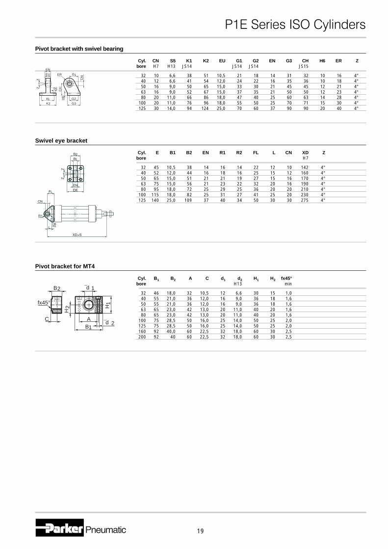
Swivel eye bracket
Cyl. E B1 B2 EN R1 R2 FL L CN XD Zbore H7
32 45 10,5 38 14 16 14 22 12 10 142 4°40 52 12,0 44 16 18 16 25 15 12 160 4°50 65 15,0 51 21 21 19 27 15 16 170 4°63 75 15,0 56 21 23 22 32 20 16 190 4°80 95 18,0 72 25 29 25 36 20 20 210 4°
100 115 18,0 82 25 31 27 41 25 20 230 4°125 140 25,0 109 37 40 34 50 30 30 275 4°
Pivot bracket for MT4
Cyl. B1 B2 A C d1 d2 H1 H2 fx45°bore H13 min
32 46 18,0 32 10,5 12 6,6 30 15 1,040 55 21,0 36 12,0 16 9,0 36 18 1,650 55 21,0 36 12,0 16 9,0 36 18 1,663 65 23,0 42 13,0 20 11,0 40 20 1,680 65 23,0 42 13,0 20 11,0 40 20 1,6
100 75 28,5 50 16,0 25 14,0 50 25 2,0125 75 28,5 50 16,0 25 14,0 50 25 2,0160 92 40,0 60 22,5 32 18,0 60 30 2,5200 92 40 60 22,5 32 18,0 60 30 2,5
Pivot bracket with swivel bearing
Cyl. CN S5 K1 K2 EU G1 G2 EN G3 CH H6 ER Zbore H7 H13 JS14 JS14 JS14 JS15
32 10 6,6 38 51 10,5 21 18 14 31 32 10 16 4°40 12 6,6 41 54 12,0 24 22 16 35 36 10 18 4°50 16 9,0 50 65 15,0 33 30 21 45 45 12 21 4°63 16 9,0 52 67 15,0 37 35 21 50 50 12 23 4°80 20 11,0 66 86 18,0 47 40 25 60 63 14 28 4°
100 20 11,0 76 96 18,0 55 50 25 70 71 15 30 4°125 30 14,0 94 124 25,0 70 60 37 90 90 20 40 4°
¯d
H
BA
2
1
H1
1¯d 2
C
fx45°
B2
5
G
¯CN
CH
G2
G3
1ER
H6
KK12
S¯
EU
ZZ
EN
�������������� ������
20
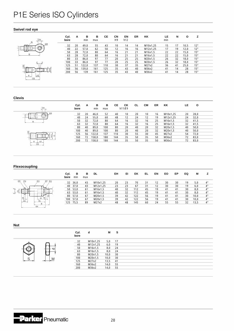
Swivel rod eye
Cyl. A B B CE CN EN ER KK LE N O Zbore min max H9 h12 min
32 20 49,0 55 43 10 14 14 M10x1,25 15 17 10,5 12°40 22 57,0 62 50 12 16 16 M12x1,25 17 19 12,0 12°50 28 72,0 80 64 16 21 21 M16x1,5 22 22 15,0 15°63 28 72,0 80 64 16 21 21 M16x1,5 22 22 15,0 15°80 33 86,0 97 77 20 25 25 M20x1,5 26 32 18,0 15°
100 33 86,0 97 77 20 25 25 M20x1,5 26 32 18,0 15°125 51 122,0 137 110 30 37 35 M27x2 36 41 25,0 15°160 56 139,0 161 125 35 43 40 M36x2 41 14 28 15°200 56 139 161 125 35 43 40 M36x2 41 14 28 15°
Clevis
Cyl. A B B CE CK CL CM ER KK LE Obore min max h11/E9
32 20 46,0 52 40 10 20 10 16 M10x1,25 20 28,040 24 55,0 60 48 12 24 12 19 M12x1,25 24 32,050 32 72,0 80 64 16 32 16 25 M16x1,5 32 41,563 32 72,0 80 64 16 32 16 25 M16x1,5 32 41,580 40 89,0 100 80 20 40 20 32 M20x1,5 40 50,0
100 40 89,0 100 80 20 40 20 32 M20x1,5 40 50,0125 56 122,0 137 110 30 55 30 45 M27x2 54 72,0160 72 158,0 180 144 35 50 35 50 M36x2 72 83,0200 72 158,0 180 144 35 50 35 50 M36x2 72 83,0
Flexocoupling
Cyl. B B DL EH EI EK EL EN EO EP EQ M Zbore min max
32 36,0 43 M10x1,25 20 23 70 31 12 30 30 19 5,0 4°40 37,0 43 M12x1,25 23 23 67 31 12 30 30 19 6,0 4°50 53,0 61 M16x1,5 40 32 112 45 19 41 41 30 8,0 4°63 53,0 61 M16x1,5 40 32 112 45 19 41 41 30 8,0 4°80 57,0 67 M20x1,5 39 42 122 56 19 41 41 30 10,0 4°
100 57,0 67 M20x1,5 39 42 122 56 19 41 41 30 10,0 4°125 75,5 89 M27x2 48 48 145 60 24 55 55 32 13,5 4°
Nut
Cyl. d M Sbore
32 M10x1,25 5,0 1740 M12x1,25 6,0 1950 M16x1,5 8,0 2463 M16x1,5 8,0 2480 M20x1,5 10,0 30
100 M20x1,5 10,0 30125 M27x2 13,5 41160 M36x2 14,0 55200 M36x2 14,0 55
S M
d
DL
ER
Z
M
Z
DL
EN EO EP EQ
EI
EL
B
EK
EK
M
¯CK
B
ER
CELEA
CL
CM O
KK
M
¯CN
B
N
Z
ACE
LE
O
KK
EN
ER
ZM
�������������� ������
21
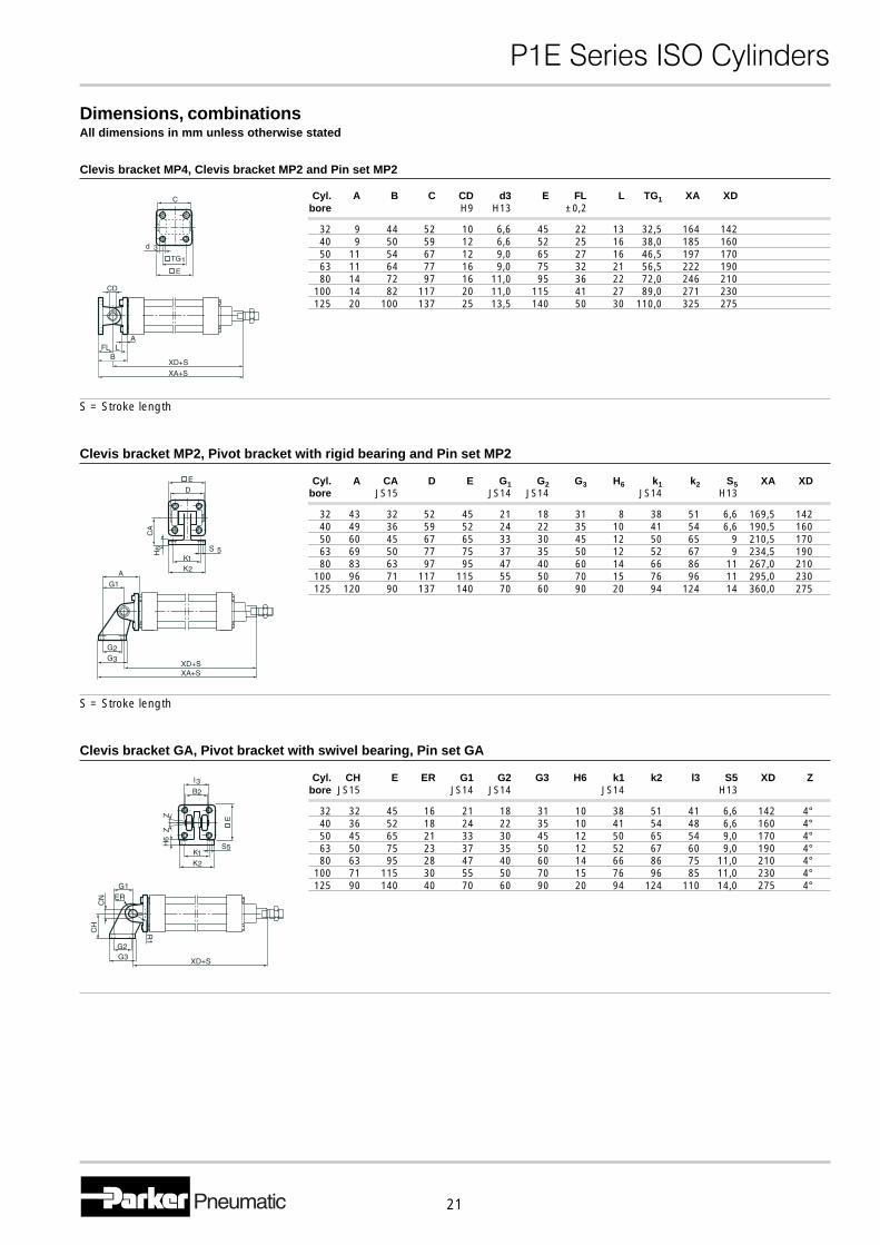
Dimensions, combinationsAll dimensions in mm unless otherwise stated
Clevis bracket MP4, Clevis bracket MP2 and Pin set MP2
Cyl. A B C CD d3 E FL L TG1 XA XDbore H9 H13 ±0,2
32 9 44 52 10 6,6 45 22 13 32,5 164 14240 9 50 59 12 6,6 52 25 16 38,0 185 16050 11 54 67 12 9,0 65 27 16 46,5 197 17063 11 64 77 16 9,0 75 32 21 56,5 222 19080 14 72 97 16 11,0 95 36 22 72,0 246 210
100 14 82 117 20 11,0 115 41 27 89,0 271 230125 20 100 137 25 13,5 140 50 30 110,0 325 275
S = Stroke length
Clevis bracket MP2, Pivot bracket with rigid bearing and Pin set MP2
Cyl. A CA D E G1 G2 G3 H6 k1 k2 S5 XA XDbore JS15 JS14 JS14 JS14 H13
32 43 32 52 45 21 18 31 8 38 51 6,6 169,5 14240 49 36 59 52 24 22 35 10 41 54 6,6 190,5 16050 60 45 67 65 33 30 45 12 50 65 9 210,5 17063 69 50 77 75 37 35 50 12 52 67 9 234,5 19080 83 63 97 95 47 40 60 14 66 86 11 267,0 210
100 96 71 117 115 55 50 70 15 76 96 11 295,0 230125 120 90 137 140 70 60 90 20 94 124 14 360,0 275
S = Stroke length
Clevis bracket GA, Pivot bracket with swivel bearing, Pin set GA
Cyl. CH E ER G1 G2 G3 H6 k1 k2 l3 S5 XD Zbore JS15 JS14 JS14 JS14 H13
32 32 45 16 21 18 31 10 38 51 41 6,6 142 4°40 36 52 18 24 22 35 10 41 54 48 6,6 160 4°50 45 65 21 33 30 45 12 50 65 54 9,0 170 4°63 50 75 23 37 35 50 12 52 67 60 9,0 190 4°80 63 95 28 47 40 60 14 66 86 75 11,0 210 4°
100 71 115 30 55 50 70 15 76 96 85 11,0 230 4°125 90 140 40 70 60 90 20 94 124 110 14,0 275 4°
�������������� ������
22
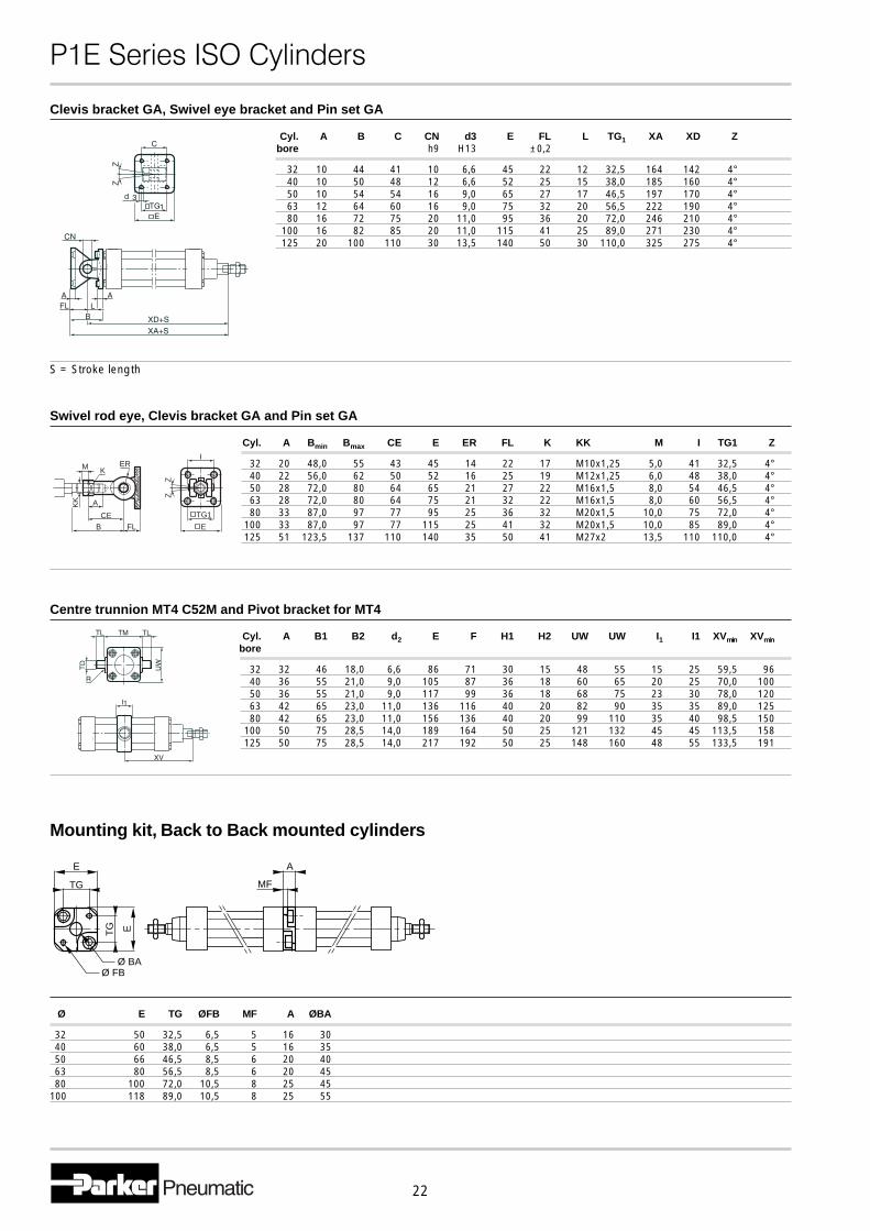
Clevis bracket GA, Swivel eye bracket and Pin set GA
Cyl. A B C CN d3 E FL L TG1 XA XD Zbore h9 H13 ±0,2
32 10 44 41 10 6,6 45 22 12 32,5 164 142 4°40 10 50 48 12 6,6 52 25 15 38,0 185 160 4°50 10 54 54 16 9,0 65 27 17 46,5 197 170 4°63 12 64 60 16 9,0 75 32 20 56,5 222 190 4°80 16 72 75 20 11,0 95 36 20 72,0 246 210 4°
100 16 82 85 20 11,0 115 41 25 89,0 271 230 4°125 20 100 110 30 13,5 140 50 30 110,0 325 275 4°
S = Stroke length
Swivel rod eye, Clevis bracket GA and Pin set GA
Cyl. A Bmin Bmax CE E ER FL K KK M I TG1 Z
32 20 48,0 55 43 45 14 22 17 M10x1,25 5,0 41 32,5 4°40 22 56,0 62 50 52 16 25 19 M12x1,25 6,0 48 38,0 4°50 28 72,0 80 64 65 21 27 22 M16x1,5 8,0 54 46,5 4°63 28 72,0 80 64 75 21 32 22 M16x1,5 8,0 60 56,5 4°80 33 87,0 97 77 95 25 36 32 M20x1,5 10,0 75 72,0 4°
100 33 87,0 97 77 115 25 41 32 M20x1,5 10,0 85 89,0 4°125 51 123,5 137 110 140 35 50 41 M27x2 13,5 110 110,0 4°
Centre trunnion MT4 C52M and Pivot bracket for MT4
Cyl. A B1 B2 d2 E F H1 H2 UW UW I1 I1 XVmin XVminbore
32 32 46 18,0 6,6 86 71 30 15 48 55 15 25 59,5 9640 36 55 21,0 9,0 105 87 36 18 60 65 20 25 70,0 10050 36 55 21,0 9,0 117 99 36 18 68 75 23 30 78,0 12063 42 65 23,0 11,0 136 116 40 20 82 90 35 35 89,0 12580 42 65 23,0 11,0 156 136 40 20 99 110 35 40 98,5 150
100 50 75 28,5 14,0 189 164 50 25 121 132 45 45 113,5 158125 50 75 28,5 14,0 217 192 50 25 148 160 48 55 133,5 191
Mounting kit, Back to Back mounted cylinders
Ø E TG ØFB MF A ØBA
32 50 32,5 6,5 5 16 3040 60 38,0 6,5 5 16 3550 66 46,5 8,5 6 20 4063 80 56,5 8,5 6 20 4580 100 72,0 10,5 8 25 45
100 118 89,0 10,5 8 25 55
E
TG
Ø FB
ETG
A
MF
Ø BA
I
TG1
E
ZZ
A
KERM
CEB FL
KK
�������������� ������
23
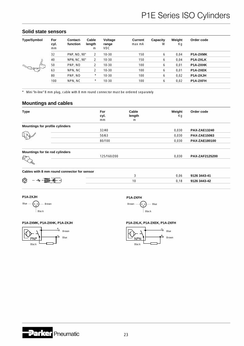
Solid state sensors
Type/Symbol For Contact- Cable Voltage Current Capacity Weight Order codecyl. function length range max mA W Kgmm m VDC
32 PNP, NO, 90° 2 10-30 150 6 0,04 P1A-2XMK
40 NPN, NC, 90° 2 10-30 150 6 0,04 P1A-2XLK
50 PNP, NO 2 10-30 100 6 0,01 P1A-2XHK
63 NPN, NC 2 10-30 100 6 0,01 P1A-2XEK
80 PNP, NO * 10-30 100 6 0,02 P1A-2XJH
100 NPN, NC * 10-30 100 6 0,02 P1A-2XFH
* Mini "in-line" 8 mm plug, cable with 8 mm round connector must be ordered separately
Mountings and cables
Type For Cable Weight Order codecyl. length Kgmm m
Mountings for profile cylinders32/40 0,030 PAX-ZAE13240
50/63 0,030 PAX-ZAE15063
80/100 0,030 PAX-ZAE180100
Mountings for tie rod cylinders125/160/200 0,030 PAX-ZAF2125200
Cables with 8 mm round connector for sensor3 0,06 9126 3443-41
10 0,18 9126 3443-42
Black
Blue
Brown
P1A-2XMK, P1A-2XHK, P1A-2XJH
Black
Blue
Brown
P1A-2XLK, P1A-2XEK, P1A-2XFH
Black
BlueBrown
P1A-2XFHP1A-2XJH
Black
Blue Brown
�������������� ������
24
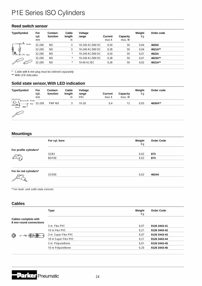
Solid state sensor, With LED indication
Type/Symbol For Contact- Cable Voltage Weight Order codecyl. function length range Current Capacity Kgmm m VDC max A max, W
32-200 PNP NO 3 10-28 0,4 12 0,05 4630A**
Mountings
For cyl. bore Weight Order CodeKg
For profile cylinders*32/63 0,02 873
80/100 0,02 874
For tie rod cylinders*32/200 0,02 4624A
* For reed- and solid state sensors
Cables
Type Weight Order CodeKg
Cables complete with8 mm round connections
3 m Flex PVC 0,07 9126 3443-41
10 m Flex PVC 0,21 9126 3443-42
3 m Super Flex PVC 0,07 9126 3443-43
10 m Super Flex PVC 0,21 9126 3443-44
3 m Polyurethene 0,01 9126 3443-45
10 m Polyurethene 0,20 9126 3443-46
Black
Blue
Brown
Reed switch sensor
Type/Symbol For Contact- Cable Voltage Weight Order codecyl. function length range Current Capacity Kgmm m max A max, W
32-200 NO 3 10-240 AC/300 DC 0,50 50 0,04 4620A
32-200 NO 3 10-240 AC/300 DC 0,38 50 0,04 4621A**
32-200 NO * 10-240 AC/300 DC 0,50 50 0,01 4622A
32-200 NO * 10-240 AC/300 DC 0,38 50 0,01 4623A**
32-200 NO * 10-60 AC/DC 0,38 50 0,02 4631A**
* Cable with 8 mm plug must be ordered separately** With LED indication
Brown
Blue
�������������� ������
25
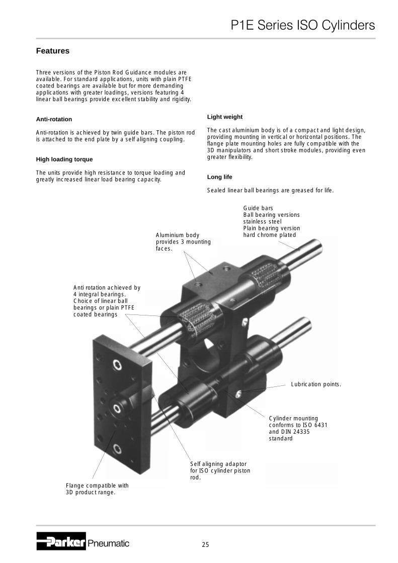
Features
Three versions of the Piston Rod Guidance modules areavailable. For standard applications, units with plain PTFEcoated bearings are available but for more demandingapplications with greater loadings, versions featuring 4linear ball bearings provide excellent stability and rigidity.
Anti-rotation
Anti-rotation is achieved by twin guide bars. The piston rodis attached to the end plate by a self aligning coupling.
High loading torque
The units provide high resistance to torque loading andgreatly increased linear load bearing capacity.
Light weight
The cast aluminium body is of a compact and light design,providing mounting in vertical or horizontal positions. Theflange plate mounting holes are fully compatible with the3D manipulators and short stroke modules, providing evengreater flexibility.
Long life
Sealed linear ball bearings are greased for life.
Flange compatible with3D product range.
Self aligning adaptorfor ISO cylinder pistonrod.
Cylinder mountingconforms to ISO 6431and DIN 24335standard
Lubrication points.
Anti rotation achieved by4 integral bearings.Choice of linear ballbearings or plain PTFEcoated bearings
Aluminium bodyprovides 3 mountingfaces.
Guide barsBall bearing versionsstainless steelPlain bearing versionhard chrome plated
�������������� ������
26
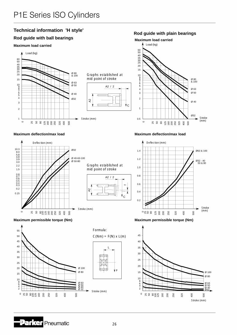
Technical information 'H style'
Maximum permissible torque (Nm)
25 50 80 100
125
160
200
250
320
400
5000
108642
15
20
25
30
35
40
50
55
45
Ø 100
Ø 32Ø 40Ø 50Ø 63
Ø 80
Stroke (mm)
Maximum permissible torque (Nm)
0
108642
15
20
25
30
35
45
40
25 50 80 100
125
160
200
250
320
400
500
Ø 100
Ø 80
Ø 63Ø 50
Ø32Ø 40
Stroke (mm)
F
L
Formula:
C(Nm) = F(N) x L(m)
60504035302520
15
10987654
3
2
1
Ø 80& 100
Ø 63Ø 50
Ø 40
Ø32
0 25 50 500
400
320
250
200
160
12580
Load (kg)
Stroke (mm)
Maximum load carried
0 25 50 80 125
160
200
250
320
400
500
100
0.15
0.2
0.30.40.50.60.70.8
1.5
2.2
3.03.94.85.88.0
10.3 Ø32
Ø 40-63-100Ø 50-80
Stroke (mm)
Deflection (mm)
Maximum deflection/max load
00
Maximum deflection/max load
Stroke(mm)
60504035302520
15
910
78
654
3
2
1
0.5
25 50 80 125
160
200
250
320
400
500
Maximum load carriedLoad (kg)
Stroke(mm)
Ø32
Ø 40
Ø 50
Ø 63
Ø 80& 100
0.2
0.4
0.6
0.8
1.0
1.2
1.4
25 50 80 125
160
200
250
320
400
500
Ø63 & 100
Ø32 - 40 50 & 80
Deflection (mm)
C
f
A2 / 2
A2
Graphs established atmid point of stroke
A2 / 2A
2
C
Graphs established atmid point of stroke
Rod guide with ball bearingsRod guide with plain bearings
�������������� ������
27
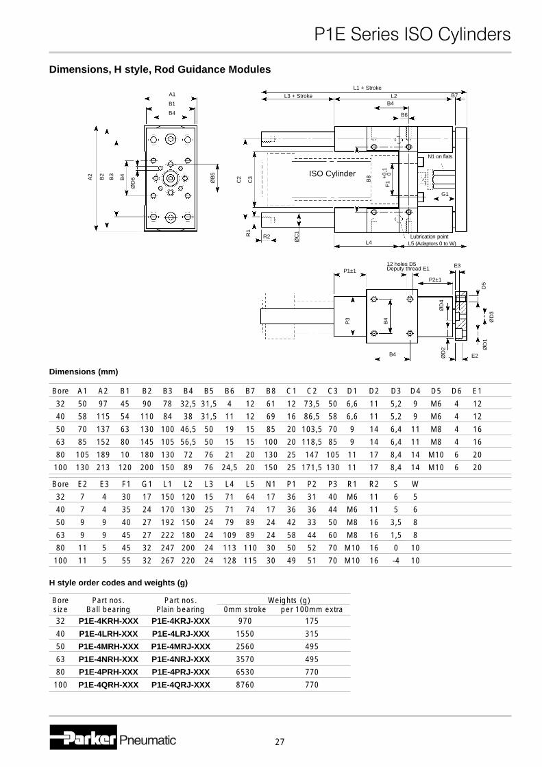
Dimensions, H style, Rod Guidance Modules
ØD
6B4
B3
B2
A2
ØB
5
B4
B1
A1
B6
B4
B7L3 + Stroke
L1 + Stroke
L2
R1
R2
ØC
1
C3
C2
N1 on flats
G1
ISO Cylinder
F1
+0,
1 0
B8
Lubrication pointL5 (Adaptors 0 to W)L4
P1±1
P2±1
12 holes D5Deputy thread E1
P3
B4
ØD
2 ØD
1Ø
D3
D5
ØD
4
B4
E3
Dimensions (mm)
Bore A1 A2 B1 B2 B3 B4 B5 B6 B7 B8 C1 C2 C3 D1 D2 D3 D4 D5 D6 E1
32 50 97 45 90 78 32,5 31,5 4 12 61 12 73,5 50 6,6 11 5,2 9 M6 4 12
40 58 115 54 110 84 38 31,5 11 12 69 16 86,5 58 6,6 11 5,2 9 M6 4 12
50 70 137 63 130 100 46,5 50 19 15 85 20 103,5 70 9 14 6,4 11 M8 4 16
63 85 152 80 145 105 56,5 50 15 15 100 20 118,5 85 9 14 6,4 11 M8 4 16
80 105 189 10 180 130 72 76 21 20 130 25 147 105 11 17 8,4 14 M10 6 20
100 130 213 120 200 150 89 76 24,5 20 150 25 171,5 130 11 17 8,4 14 M10 6 20
Bore E2 E3 F1 G1 L1 L2 L3 L4 L5 N1 P1 P2 P3 R1 R2 S W
32 7 4 30 17 150 120 15 71 64 17 36 31 40 M6 11 6 5
40 7 4 35 24 170 130 25 71 74 17 36 36 44 M6 11 5 6
50 9 9 40 27 192 150 24 79 89 24 42 33 50 M8 16 3,5 8
63 9 9 45 27 222 180 24 109 89 24 58 44 60 M8 16 1,5 8
80 11 5 45 32 247 200 24 113 110 30 50 52 70 M10 16 0 10
100 11 5 55 32 267 220 24 128 115 30 49 51 70 M10 16 -4 10
Bore Part nos. Part nos. Weights (g)size Ball bearing Plain bearing 0mm stroke per 100mm extra32 P1E-4KRH-XXX P1E-4KRJ-XXX 970 175
40 P1E-4LRH-XXX P1E-4LRJ-XXX 1550 315
50 P1E-4MRH-XXX P1E-4MRJ-XXX 2560 495
63 P1E-4NRH-XXX P1E-4NRJ-XXX 3570 495
80 P1E-4PRH-XXX P1E-4PRJ-XXX 6530 770
100 P1E-4QRH-XXX P1E-4QRJ-XXX 8760 770
H style order codes and weights (g)
E2
�������������� ������
28
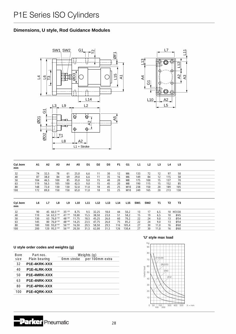
Cyl. bore A1 A2 A3 A4 A5 D1 D2 D3 F1 G1 L1 L2 L3 L4 L5mm
32 74 32,5 78 61 25,0 6,6 11 30 12 M6 133 72 12 97 5040 87 38,0 84 69 29,0 6,6 11 35 16 M6 149 84 12 115 5850 104 46,5 100 85 35,0 9,0 15 40 20 M8 175 100 15 137 7063 119 56,5 105 100 42,5 9,0 15 45 20 M8 190 115 15 152 8580 148 72,0 130 130 52,0 11,0 18 45 25 M10 238 150 20 189 105
100 172 89,0 150 150 65,0 11,0 18 55 25 M10 249 165 20 213 130
Cyl. bore L6 L7 L8 L9 L10 L11 L12 L13 L14 L15 SW1 SW2 T1 T2 T3mm
32 90 45 60,5+2/0 35+2/0 8,75 9,5 32,25 18,0 44 50,2 13 17 6,5 10 HEX3040 110 54 63,5+2/0 41+2/0 10,00 15,5 38,50 23,0 51 58,2 15 19 6,5 10 Ø4550 130 63 76,0+5/0 48+4/0 11,75 18,5 45,25 26,0 60 70,2 22 24 9,0 13 Ø5463 145 80 76,0+5/0 48+4/0 14,25 23,5 47,75 26,0 75 85,2 22 24 9,0 13 Ø5480 180 100 93,0+6/0 56+6/0 16,50 29,5 58,50 29,5 116 105,4 27 30 11,0 16 Ø60
100 200 120 95,5+6/0 56+6/0 20,50 31,5 62,00 31,5 126 130,4 27 30 11,0 16 Ø60
A2
L5
L10
L13
A4
G1
L7
L12
A2
L11
A3
SW1 SW2 G1
ØD
3
T2
L15
A1
ØF
1
L6L4
L14
ØD
1
T1
L8 A2ØD
2
L9L3 L2
G1
A5
A2
T3
L1 + Stroke
Dimensions, U style, Rod Guidance Modules
Bore Part nos. Weights (g)size Plain bearing 0mm stroke per 100mm extra32 P1E-4KRK-XXX
40 P1E-4LRK-XXX
50 P1E-4MRK-XXX
63 P1E-4NRK-XXX
80 P1E-4PRK-XXX
100 P1E-4QRK-XXX
U style order codes and weights (g)
'U' style max load
�������������� ������
29
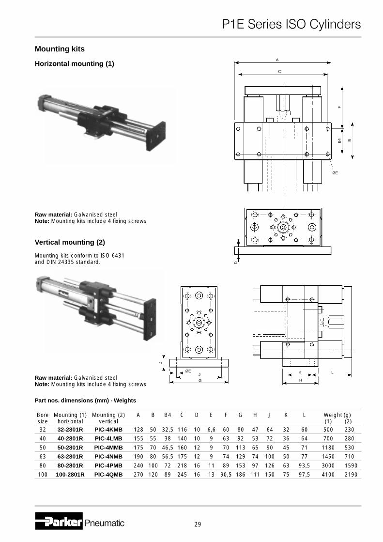
Mounting kits
Bore Mounting (1) Mounting (2) A B B4 C D E F G H J K L Weight (g)size horizontal vertical (1) (2)32 32-2801R PIC-4KMB 128 50 32,5 116 10 6,6 60 80 47 64 32 60 500 230
40 40-2801R PIC-4LMB 155 55 38 140 10 9 63 92 53 72 36 64 700 280
50 50-2801R PIC-4MMB 175 70 46,5 160 12 9 70 113 65 90 45 71 1180 530
63 63-2801R PIC-4NMB 190 80 56,5 175 12 9 74 129 74 100 50 77 1450 710
80 80-2801R PIC-4PMB 240 100 72 218 16 11 89 153 97 126 63 93,5 3000 1590
100 100-2801R PIC-4QMB 270 120 89 245 16 13 90,5 186 111 150 75 97,5 4100 2190
Part nos. dimensions (mm) - Weights
A
C
F
BB4
ØE
D
K
H
L
G
JØE
D
Horizontal mounting (1)
Raw material: Galvanised steelNote: Mounting kits include 4 fixing screws
Vertical mounting (2)
Mounting kits conform to ISO 6431and DIN 24335 standard.
Raw material: Galvanised steelNote: Mounting kits include 4 fixing screws
�������������� ������
30
4637
4638
4639
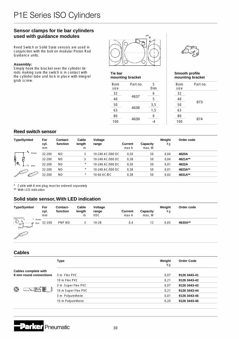
Sensor clamps for tie bar cylindersused with guidance modules
Bore Part no. Ssize Dim32 6
40 5
50 3,5
63 1,5
80 0
100 -4
Tie barmounting bracket
Reed Switch or Solid State sensors are used inconjunction with the bolt on modular Piston RodGuidance units.
S
Assembly:Simply hook the bracket over the cylinder tierods making sure the switch is in contact withthe cylinder tube and lock in place with integralgrub screw.
Bore Part no.size32
40
50
63
80
100
Smooth profilemounting bracket
873
874
Reed switch sensor
Type/Symbol For Contact- Cable Voltage Weight Order codecyl. function length range Current Capacity Kgmm m max A max, W
32-200 NO 3 10-240 AC/300 DC 0,50 50 0,04 4620A
32-200 NO 3 10-240 AC/300 DC 0,38 50 0,04 4621A**
32-200 NO * 10-240 AC/300 DC 0,50 50 0,01 4622A
32-200 NO * 10-240 AC/300 DC 0,38 50 0,01 4623A**
32-200 NO * 10-60 AC/DC 0,38 50 0,02 4631A**
* Cable with 8 mm plug must be ordered separately** With LED indication
Brown
Blue
Solid state sensor, With LED indication
Type/Symbol For Contact- Cable Voltage Weight Order codecyl. function length range Current Capacity Kgmm m VDC max A max, W
32-200 PNP NO 3 10-28 0,4 12 0,05 4630A**
Cables
Type Weight Order CodeKg
Cables complete with8 mm round connections 3 m Flex PVC 0,07 9126 3443-41
10 m Flex PVC 0,21 9126 3443-42
3 m Super Flex PVC 0,07 9126 3443-43
10 m Super Flex PVC 0,21 9126 3443-44
3 m Polyurethene 0,01 9126 3443-45
10 m Polyurethene 0,20 9126 3443-46
Black
Blue
Brown
�������������� ������
31
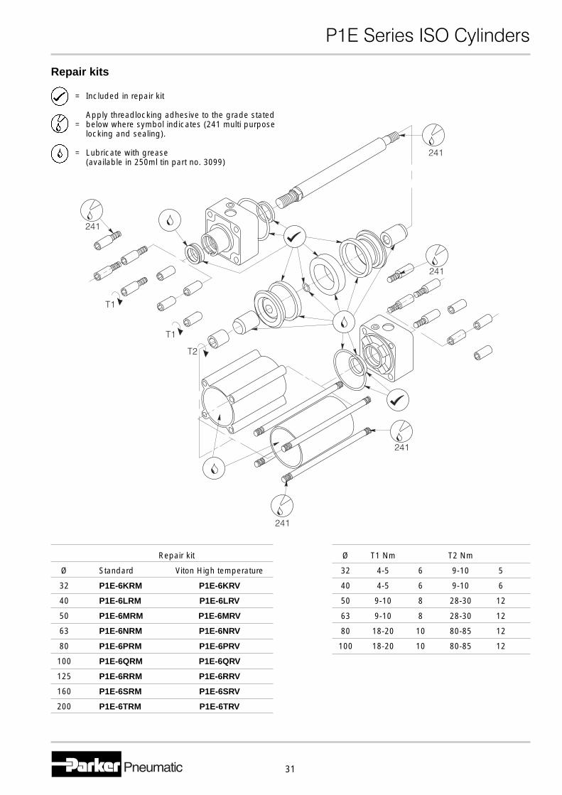
Repair kits
= Included in repair kit
Apply threadlocking adhesive to the grade stated= below where symbol indicates (241 multi purpose
locking and sealing).
= Lubricate with grease(available in 250ml tin part no. 3099)
Repair kit
Ø Standard Viton High temperature
32 P1E-6KRM P1E-6KRV
40 P1E-6LRM P1E-6LRV
50 P1E-6MRM P1E-6MRV
63 P1E-6NRM P1E-6NRV
80 P1E-6PRM P1E-6PRV
100 P1E-6QRM P1E-6QRV
125 P1E-6RRM P1E-6RRV
160 P1E-6SRM P1E-6SRV
200 P1E-6TRM P1E-6TRV
Ø T1 Nm T2 Nm
32 4-5 6 9-10 5
40 4-5 6 9-10 6
50 9-10 8 28-30 12
63 9-10 8 28-30 12
80 18-20 10 80-85 12
100 18-20 10 80-85 12