Embed Size (px)
Citation preview
P4-IPsec: Site-to-Site and Host-to-Site VPN withIPsec in P4-Based SDN
Frederik Hauser, Marco Häberle, Mark Schmidt, Michael Menth
Abstract—In this work, we present P4-IPsec, a conceptfor IPsec in software-defined networks (SDN) using P4 pro-grammable data planes. The prototype implementation featuresESP in tunnel mode and supports different cipher suites. P4-capable switches are programmed to serve as IPsec tunnelendpoints. We also provide a client agent to configure tunnelendpoints on Linux hosts so that site-to-site and host-to-siteapplication scenarios can be supported which are the base forvirtual private networks (VPNs). While traditional VPNs requirecomplex key exchange protocols like IKE to set up and renewtunnel endpoints, P4-IPsec benefits from an SDN controller toaccomplish these tasks. One goal of this experimental workis to investigate how well P4-IPsec can be implemented onexisting P4 switches. We present a prototype for the BMv2P4 software switch, evaluate its performance, and publish itssource code on GitHub [1]. We explain why we could notprovide a useful implementation with the NetFPGA SUMEboard. For the Edgecore Wedge 100BF-32X Tofino-based switch,we presented two prototype implementations to cope with amissing crypto unit. As another contribution of this paper, weprovide technological background of P4 and IPsec and give acomprehensive review of security applications in P4, IPsec inSDN, and IPsec data plane implementations. According to ourknowledge, P4-IPsec is the first implementation of IPsec for P4-based SDN.
Index Terms—IPsec, P4, software-defined networking, VPN
I. INTRODUCTION
Virtual Private Networks (VPNs) extend private networksacross public networks by adding authentication and encryp-tion to network traffic. Internet Protocol Security (IPsec) isone of the oldest, but still most-widespread VPN protocols.Standardized by the IETF, it introduces protection on theInternet Protocol (IP) layer. Due to its large distribution, manyimplementations for network appliances and operating systemsare available. Although it is criticized for its complexity,proven deployment patterns allow efficient and reliable op-eration.
IPsec tunnel setup requires user configuration plus keyingmaterial that is exchanged by IPsec peers via the Internet KeyExchange (IKE) protocol. Complexity grows with the numberof IPsec peers, especially in highly dynamic environmentssuch as campus or enterprise networks with many users andsites. Several works investigate on how to leverage the cen-tralized control plane of software-defined networking (SDN)
Frederik Hauser, Marco Häberle, Mark Schmidt, and Michael Menthare with Chair of Communication Networks, University of Tuebin-gen, Tuebingen, Germany. E-mail: {frederik.hauser,marco.haeberle,mark-thomas.schmidt,menth}@uni-tuebingen.de
This work was supported by the Deutsche Forschungsgemeinschaft (DFG)under grant ME2727/1-2 and the bwNET100G+ project which is funded bythe Ministry of Science, Research and the Arts Baden-Württemberg (MWK).The authors alone are responsible for the content of this paper.
to simplify IPsec operation. However, the possibilities forIPsec deployment in SDN were limited. Typical SDN switcheshave a fixed-function data plane that does not provide supportfor IPsec. As a result, IPsec data plane processing needs tobe moved to an additional software-based packet processingfunction (PPF). Besides being an additional component, thisadds latency as traffic needs to be forwarded back and forth.Programmable data planes as offered by P4 are a gamechanger. Data plane behavior can be described in a high-level programming language. Those network programs canbe executed by software or hardware devices. For IPsec thismeans that instead of shifting IPsec functionality to PPFs,functions such as IPsec can be implemented directly on thedata plane of SDN switches. In our previous work P4-MACsec[2], we introduced MACsec for P4-based SDN. We proposeda data plane implementation in P4 and introduced a novelconcept for automated deployment and operation of MACsec.
In this paper, we present the first integration of IPsecVPN for P4-based SDN. We give an introduction on thetechnological background and provide an extensive survey onrelated work in that field. We present an IPsec data plane im-plementation that integrates IPsec components and processeswith constructs and components under the given constraintsof the P4 data plane programming language. Cryptographicoperations for authentication, encryption, and decryption areimplemented in P4 externs where IPsec components such asthe Security Policy Database (SPD) and Security AssociationDatabase (SAD) are part of the P4 processing pipeline. P4switches that implement the functionality of P4-IPsec canbe deployed in host-to-site and site-to-site VPN scenarios.Control plane functions for IPsec operation are part of acentral SDN controller that maintains IPsec tunnels withoutthe help of distributed key exchange protocols such as IKE.As these components are steered by a centralized control planethrough an authenticated and encrypted control connection,complex IKE-based key exchange protocols are substitutedby controller-based tunnel setup and renewal procedures.For host-to-site operation, we introduce a client agent forLinux operating systems that runs on the roadwarrior hosts.It establishes an interface to the central SDN controller viaa gRPC connection. To investigate how well P4-IPsec canbe implemented on existing P4 targets, we work on threeprototypes. We successfuly implement a prototype for theBehavioral Model version 2 (BMv2) P4 software target andconduct a performance evaluation. We release the source codeof our prototype along its testbed environment under theApache v2 license on GitHub [1]. In addition, we report onimplementation experiences for the NetFPGA SUME boardand Edgecore Wedge 100BF-32X P4 switch. For the latter, we
arX
iv:1
907.
0359
3v2
[cs
.NI]
5 J
ul 2
020
present two workaround implementation and compare them inperformance experiments.
P4-IPsec introduces several benefits over traditional IPsecoperation. First, we improve scalability by making switchesand roadwarrior hosts stateless components whose functional-ity is only managed by an SDN controller. Second, we improveflexibility by converting P4 targets into IPsec endpoints, i.e.,IPsec tunnels can terminate close to the network hosts thatshould be made accessible via the VPN. This limits the sizeof the perimeter and improves security through better isolation.Last, we encourage open networking research and operation.Network functionality can be modified in agile developmentprocesses, source code can be audited and improved by a largeraudience.
The rest of the paper is organized as follows. Section IIgives an overview on IPsec VPN and data plane programmingwith P4. In Section III, we describe related work on P4-basednetwork security applications, IPsec in SDN, and IPsec dataplane implementations. Section IV presents the architecture ofP4-IPsec. In Section V, we describe the prototypical imple-mentation of P4-IPsec with Mininet and BMv2. Section VIpresents the performance evaluation of that prototype. InSection VII, we report implementation experiences for theNetFPGA SUME and Edgecore Wedge 100BF-32X P4 targets.Section VIII concludes this work. The appendices include alist of the acronyms used in the paper.
II. TECHNICAL BACKGROUND
We give an introduction to VPN with IPsec and data planeprogramming with P4.
A. IPsec VPNInternet Protocol Security (IPsec) is a widespread VPN
protocol suite. It applies authentication and encryption on theIP in host-to-host, gateway-to-gateway, and host-to-gatewaycommunication scenarios. RFC 4301 [3] is the latest versionof its specification.
1) Protocols: IPsec comprises the Authentication Header(AH) and Encrypted Secured Payload (ESP) protocol. AH[4] protects IP packets by sender authentication and packetintegrity validation. It applies a hash function with a sharedkey (e.g., HMAC-SHA256) to calculate Integrity Check Val-ues (ICVs) and adds packet sequence numbers to protectagainst replay attacks. ESP [5] protects the confidentialityof IP packets by symmetric encryption. As for AH, it alsoadds sender authentication, packet integrity validation, andprotection against replay attacks. ESP supports symmetricciphers such as Triple Data Encryption Standard (3DES),Blowfish, and Advanced Encryption Standard (AES). Ciphersthat only apply encryption are combined with an authen-tication function. AES in cipher block chaining (CBC) orcounter (CTR) mode are examples for such ciphers thatmight be combined with secure hash algorithm (SHA) forauthentication. authenticated encryption (AE) ciphers such asAES in galois/counter mode (GCM) [6] include both, packetencryption and authentication. IPsec provides support for IPPayload Compression (IPComp) [7] so that the payload of IPpackets can be compressed before encryption.
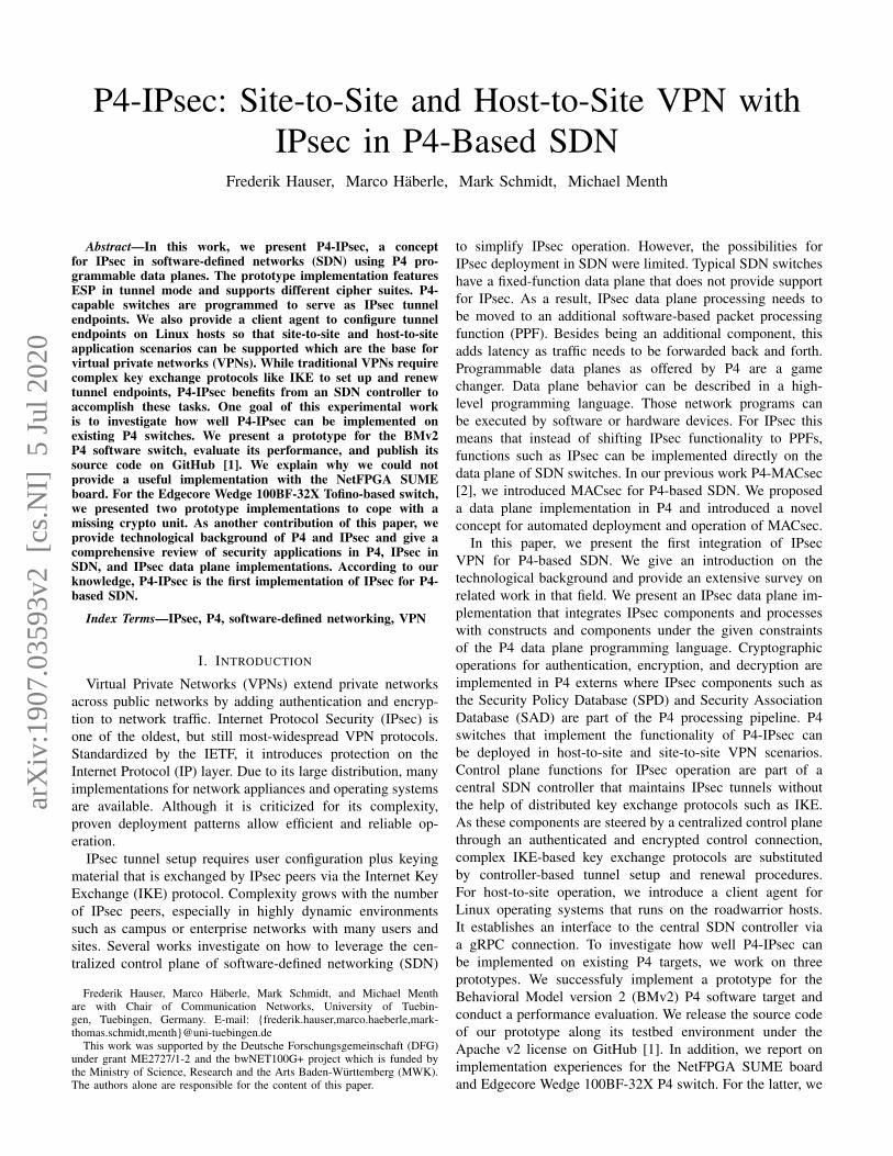
2) Operation Modes: IPsec can be deployed in eithertransport or tunnel operation mode. Transport mode protectsIP traffic that is exchanged between two network hosts (host-to-host scenario). An AH or ESP header is inserted betweenthe IP header and the IP payload. Tunnel mode protects IPtraffic host-to-host, host-to-site, and site-to-site communicationscenarios. Figure 1 depicts how tunnel mode with ESP isapplied to an IP packet. A new outer IP header with theIP addresses of the IPsec peers is created. The original IPpacket is inserted between the ESP header and the ESP trailer.Encryption protects the original IP packet while authenticationis applied to the complete ESP packet.
IP header
IP payload Original IP packet
ESP header
Outer IP header
IP header
IP payload
ESP trailer
IPsecpacket
ESP auth.
Encrypted
Authenticated
Fig. 1. Tunnel mode with ESP. The original IP packet is inserted betweenthe ESP header and the ESP trailer. The inner IP packet is encrypted whilethe complete ESP packet is authenticated.
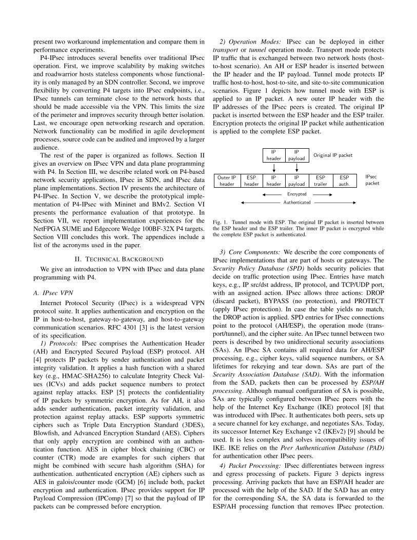
3) Core Components: We describe the core components ofIPsec implementations that are part of hosts or gateways. TheSecurity Policy Database (SPD) holds security policies thatdecide on traffic protection using IPsec. Entries have matchkeys, e.g., IP src/dst address, IP protocol, and TCP/UDP port,with an assigned action. IPsec allows three actions: DROP(discard packet), BYPASS (no protection), and PROTECT(apply IPsec protection). In case the table yields no match,the DROP action is applied. SPD entries for IPsec connectionspoint to the protocol (AH/ESP), the operation mode (trans-port/tunnel), and the cipher suite. An IPsec tunnel between twopeers is described by two unidirectional security associations(SAs). An IPsec SA contains all required data for AH/ESPprocessing, e.g., cipher keys, valid sequence numbers, or SAlifetimes for rekeying and tear down. SAs are part of theSecurity Association Database (SAD). With the informationfrom the SAD, packets then can be processed by ESP/AHprocessing. Although manual configuration of SA is possible,SAs are typically configured between IPsec peers with thehelp of the Internet Key Exchange (IKE) protocol [8] thatwas introduced with IPsec. It authenticates both peers, sets upa secure channel for key exchange, and negotiates SAs. Today,its successor Internet Key Exchange v2 (IKEv2) [9] should beused. It is less complex and solves incompatibility issues ofIKE. IKE relies on the Peer Authentication Database (PAD)for authentication other IPsec peers.
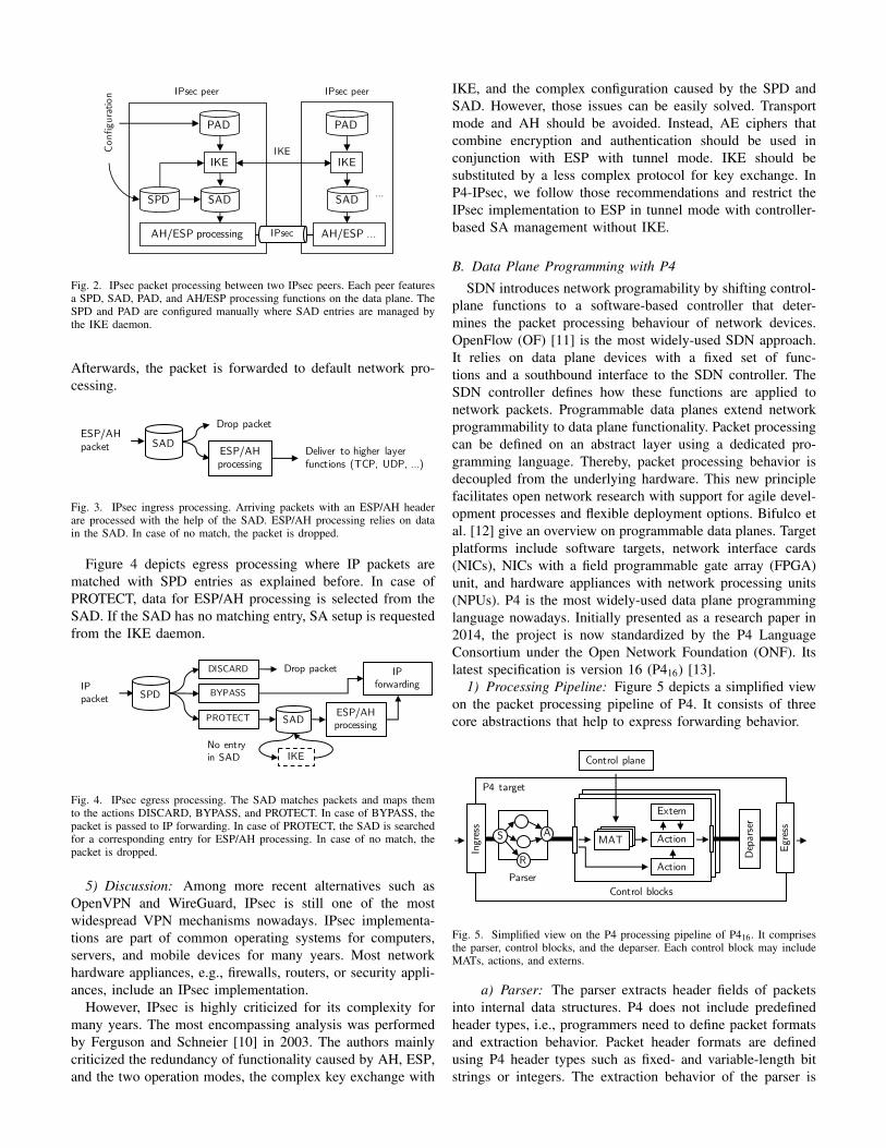
4) Packet Processing: IPsec differentiates between ingressand egress processing of packets. Figure 3 depicts ingressprocessing. Arriving packets that have an ESP/AH header areprocessed with the help of the SAD. If the SAD has an entryfor the corresponding SA, the SA data is forwarded to theESP/AH processing function that removes IPsec protection.
AH/ESP processing
IKE
IPsec peer
SPD SAD
IKE
PAD
IKE
AH/ESP …
SAD
Conf
igur
atio
n IPsec peer
…
PAD
IPsec
Fig. 2. IPsec packet processing between two IPsec peers. Each peer featuresa SPD, SAD, PAD, and AH/ESP processing functions on the data plane. TheSPD and PAD are configured manually where SAD entries are managed bythe IKE daemon.
Afterwards, the packet is forwarded to default network pro-cessing.
SADESP/AH processing
Drop packet
Deliver to higher layer functions (TCP, UDP, …)
ESP/AHpacket
Fig. 3. IPsec ingress processing. Arriving packets with an ESP/AH headerare processed with the help of the SAD. ESP/AH processing relies on datain the SAD. In case of no match, the packet is dropped.
Figure 4 depicts egress processing where IP packets arematched with SPD entries as explained before. In case ofPROTECT, data for ESP/AH processing is selected from theSAD. If the SAD has no matching entry, SA setup is requestedfrom the IKE daemon.
IKE
SPD
SAD
DISCARD
PROTECT
BYPASS
ESP/AH processing
IP forwarding
No entry in SAD
Drop packetIPpacket
Fig. 4. IPsec egress processing. The SAD matches packets and maps themto the actions DISCARD, BYPASS, and PROTECT. In case of BYPASS, thepacket is passed to IP forwarding. In case of PROTECT, the SAD is searchedfor a corresponding entry for ESP/AH processing. In case of no match, thepacket is dropped.
5) Discussion: Among more recent alternatives such asOpenVPN and WireGuard, IPsec is still one of the mostwidespread VPN mechanisms nowadays. IPsec implementa-tions are part of common operating systems for computers,servers, and mobile devices for many years. Most networkhardware appliances, e.g., firewalls, routers, or security appli-ances, include an IPsec implementation.
However, IPsec is highly criticized for its complexity formany years. The most encompassing analysis was performedby Ferguson and Schneier [10] in 2003. The authors mainlycriticized the redundancy of functionality caused by AH, ESP,and the two operation modes, the complex key exchange with
IKE, and the complex configuration caused by the SPD andSAD. However, those issues can be easily solved. Transportmode and AH should be avoided. Instead, AE ciphers thatcombine encryption and authentication should be used inconjunction with ESP with tunnel mode. IKE should besubstituted by a less complex protocol for key exchange. InP4-IPsec, we follow those recommendations and restrict theIPsec implementation to ESP in tunnel mode with controller-based SA management without IKE.
B. Data Plane Programming with P4
SDN introduces network programability by shifting control-plane functions to a software-based controller that deter-mines the packet processing behaviour of network devices.OpenFlow (OF) [11] is the most widely-used SDN approach.It relies on data plane devices with a fixed set of func-tions and a southbound interface to the SDN controller. TheSDN controller defines how these functions are applied tonetwork packets. Programmable data planes extend networkprogrammability to data plane functionality. Packet processingcan be defined on an abstract layer using a dedicated pro-gramming language. Thereby, packet processing behavior isdecoupled from the underlying hardware. This new principlefacilitates open network research with support for agile devel-opment processes and flexible deployment options. Bifulco etal. [12] give an overview on programmable data planes. Targetplatforms include software targets, network interface cards(NICs), NICs with a field programmable gate array (FPGA)unit, and hardware appliances with network processing units(NPUs). P4 is the most widely-used data plane programminglanguage nowadays. Initially presented as a research paper in2014, the project is now standardized by the P4 LanguageConsortium under the Open Network Foundation (ONF). Itslatest specification is version 16 (P416) [13].
1) Processing Pipeline: Figure 5 depicts a simplified viewon the packet processing pipeline of P4. It consists of threecore abstractions that help to express forwarding behavior.
P4 target
Ingr
ess
Egre
ss
Dep
arse
r
Parser
Action
Extern
Control blocks
S A
R Action
Control plane
MAT
Fig. 5. Simplified view on the P4 processing pipeline of P416. It comprisesthe parser, control blocks, and the deparser. Each control block may includeMATs, actions, and externs.
a) Parser: The parser extracts header fields of packetsinto internal data structures. P4 does not include predefinedheader types, i.e., programmers need to define packet formatsand extraction behavior. Packet header formats are definedusing P4 header types such as fixed- and variable-length bitstrings or integers. The extraction behavior of the parser is
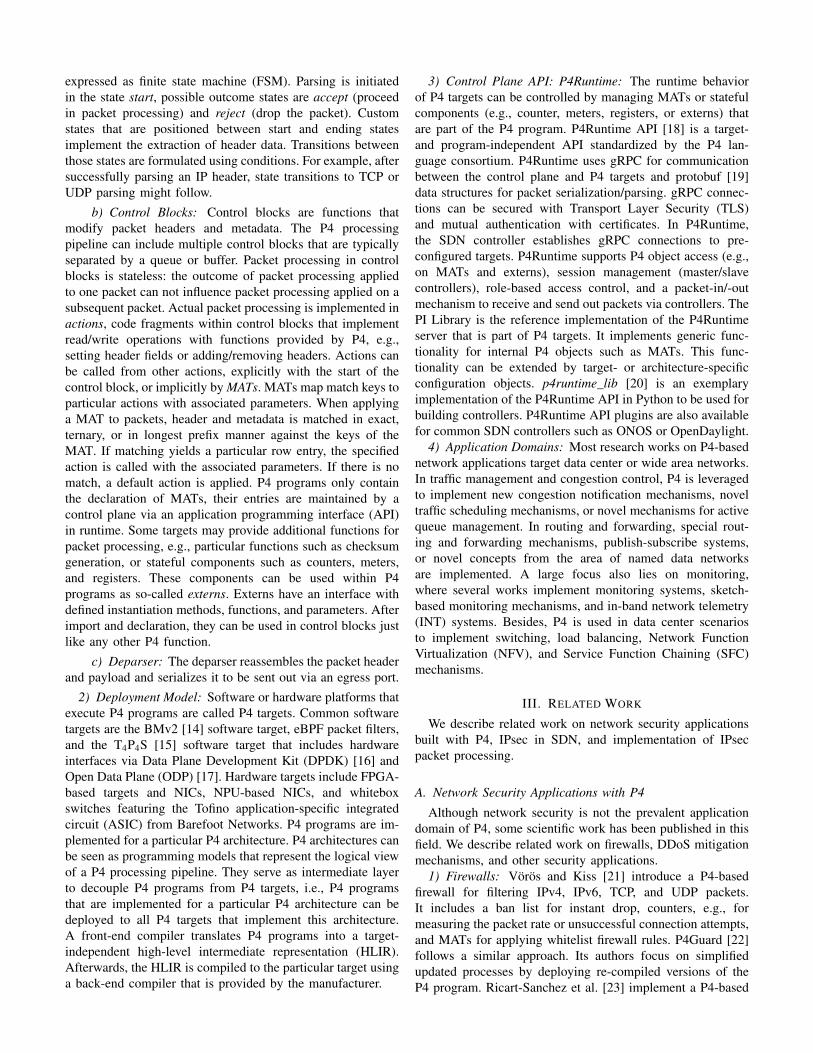
expressed as finite state machine (FSM). Parsing is initiatedin the state start, possible outcome states are accept (proceedin packet processing) and reject (drop the packet). Customstates that are positioned between start and ending statesimplement the extraction of header data. Transitions betweenthose states are formulated using conditions. For example, aftersuccessfully parsing an IP header, state transitions to TCP orUDP parsing might follow.
b) Control Blocks: Control blocks are functions thatmodify packet headers and metadata. The P4 processingpipeline can include multiple control blocks that are typicallyseparated by a queue or buffer. Packet processing in controlblocks is stateless: the outcome of packet processing appliedto one packet can not influence packet processing applied on asubsequent packet. Actual packet processing is implemented inactions, code fragments within control blocks that implementread/write operations with functions provided by P4, e.g.,setting header fields or adding/removing headers. Actions canbe called from other actions, explicitly with the start of thecontrol block, or implicitly by MATs. MATs map match keys toparticular actions with associated parameters. When applyinga MAT to packets, header and metadata is matched in exact,ternary, or in longest prefix manner against the keys of theMAT. If matching yields a particular row entry, the specifiedaction is called with the associated parameters. If there is nomatch, a default action is applied. P4 programs only containthe declaration of MATs, their entries are maintained by acontrol plane via an application programming interface (API)in runtime. Some targets may provide additional functions forpacket processing, e.g., particular functions such as checksumgeneration, or stateful components such as counters, meters,and registers. These components can be used within P4programs as so-called externs. Externs have an interface withdefined instantiation methods, functions, and parameters. Afterimport and declaration, they can be used in control blocks justlike any other P4 function.
c) Deparser: The deparser reassembles the packet headerand payload and serializes it to be sent out via an egress port.
2) Deployment Model: Software or hardware platforms thatexecute P4 programs are called P4 targets. Common softwaretargets are the BMv2 [14] software target, eBPF packet filters,and the T4P4S [15] software target that includes hardwareinterfaces via Data Plane Development Kit (DPDK) [16] andOpen Data Plane (ODP) [17]. Hardware targets include FPGA-based targets and NICs, NPU-based NICs, and whiteboxswitches featuring the Tofino application-specific integratedcircuit (ASIC) from Barefoot Networks. P4 programs are im-plemented for a particular P4 architecture. P4 architectures canbe seen as programming models that represent the logical viewof a P4 processing pipeline. They serve as intermediate layerto decouple P4 programs from P4 targets, i.e., P4 programsthat are implemented for a particular P4 architecture can bedeployed to all P4 targets that implement this architecture.A front-end compiler translates P4 programs into a target-independent high-level intermediate representation (HLIR).Afterwards, the HLIR is compiled to the particular target usinga back-end compiler that is provided by the manufacturer.
3) Control Plane API: P4Runtime: The runtime behaviorof P4 targets can be controlled by managing MATs or statefulcomponents (e.g., counter, meters, registers, or externs) thatare part of the P4 program. P4Runtime API [18] is a target-and program-independent API standardized by the P4 lan-guage consortium. P4Runtime uses gRPC for communicationbetween the control plane and P4 targets and protobuf [19]data structures for packet serialization/parsing. gRPC connec-tions can be secured with Transport Layer Security (TLS)and mutual authentication with certificates. In P4Runtime,the SDN controller establishes gRPC connections to pre-configured targets. P4Runtime supports P4 object access (e.g.,on MATs and externs), session management (master/slavecontrollers), role-based access control, and a packet-in/-outmechanism to receive and send out packets via controllers. ThePI Library is the reference implementation of the P4Runtimeserver that is part of P4 targets. It implements generic func-tionality for internal P4 objects such as MATs. This func-tionality can be extended by target- or architecture-specificconfiguration objects. p4runtime_lib [20] is an exemplaryimplementation of the P4Runtime API in Python to be used forbuilding controllers. P4Runtime API plugins are also availablefor common SDN controllers such as ONOS or OpenDaylight.
4) Application Domains: Most research works on P4-basednetwork applications target data center or wide area networks.In traffic management and congestion control, P4 is leveragedto implement new congestion notification mechanisms, noveltraffic scheduling mechanisms, or novel mechanisms for activequeue management. In routing and forwarding, special rout-ing and forwarding mechanisms, publish-subscribe systems,or novel concepts from the area of named data networksare implemented. A large focus also lies on monitoring,where several works implement monitoring systems, sketch-based monitoring mechanisms, and in-band network telemetry(INT) systems. Besides, P4 is used in data center scenariosto implement switching, load balancing, Network FunctionVirtualization (NFV), and Service Function Chaining (SFC)mechanisms.
III. RELATED WORK
We describe related work on network security applicationsbuilt with P4, IPsec in SDN, and implementation of IPsecpacket processing.
A. Network Security Applications with P4
Although network security is not the prevalent applicationdomain of P4, some scientific work has been published in thisfield. We describe related work on firewalls, DDoS mitigationmechanisms, and other security applications.
1) Firewalls: Vörös and Kiss [21] introduce a P4-basedfirewall for filtering IPv4, IPv6, TCP, and UDP packets.It includes a ban list for instant drop, counters, e.g., formeasuring the packet rate or unsuccessful connection attempts,and MATs for applying whitelist firewall rules. P4Guard [22]follows a similar approach. Its authors focus on simplifiedupdated processes by deploying re-compiled versions of theP4 program. Ricart-Sanchez et al. [23] implement a P4-based
firewall for 5G networks. It includes parser definitions forfiltering GPRS tunneling protocol (GTP) data. CoFilter [24]introduces a hash function for efficient flow identification. Itis built as P4 action and uses hashes instead of 5-tuples forflow identification to save table space. Including the functiondirectly on the packet processing devices keeps latency low.Zaballa et al. [25] and Almaini et al. [26] introduce portknocking on P4 switches.
2) DDoS Mitigation Mechanisms: Paolucci et al. [27],[28] propose a DDoS mitigation mechanism that runs on P4switches. A stateful mechanism detects and blocks DDoS portscan attacks with incremental TCP and UDP destination portnumbers. Dimolianis et al. [29] also implement a DDoS attackmitigation mechanism that runs completely on P4 switches.Collected flow data is mapped to distinct time intervals whereDDoS attacks are detected by analyzing the symmetry ratio ofincoming and outgoing traffic. TDoSD@DP [30] implementsa mitigation scheme against DDoS attacks on SIP proxies.The authors introduce a simple state machine that monitorsSIP message sequences. Valid sequences of INVITE and BYEmessages keep the port open. Febro et al. [31] implementanother DDoS mitigation mechanism for SIP INVITE DDoSattacks. P4 switches keep per-port counters for INVITE orREGISTER packets that are monitored by an SDN controllerto detect DDoS attacks. LAMP [32] implements cooperativemitigation of application layer DDoS attacks via in-band sig-naling with P4. Afek et al. [33] implement known mitigationmechanisms for SYN and DNS spoofing in DDoS attacks inP4. Lapolli et al. [34] describe a novel algorithmic approachbased on the Shannon entropy to detect and stop DDoS attackson P4 switches. Kuka et al. [35] introduce an FPGA-basedsystem for DDoS attack mitigation. P4 is used to extract headerdata from packets and send it to an SDN controller whereDDoS attack identification is implemented. Mi and Wang [36]propose a similar approach where collected data is sent to adeep learning module that runs on a server in the network.
3) Other Security Applications: Lewis et al. [37] implementan IDS offloading mechanism in P4. A rule parser translatesSnort IDS rules into MAT entries for a P4 switch. Then,IDS pipeline stages decide if packets should be forwarded,dropped, or sent to an external IDS for analysis. Poise [38]is a security-related network control system that translateshigh-level policies into P4 programs for network control. InP4-MACsec [2], we implement IEEE 802.1AE (MACsec) inP4 and introduce an automated deployment that relies onlink monitoring and MACsec provisioning. Link monitoringis implemented using a novel variant of Link Layer DiscoveryProtocol (LLDP) that relies on encrypted payloads and se-quence numbers to protect against LLDP packet manipulationsand replay attacks.
B. IPsec in SDN
Several works investigate the application of SDN to IPsecoperation. We describe operation modes, southbound inter-faces, and use cases.
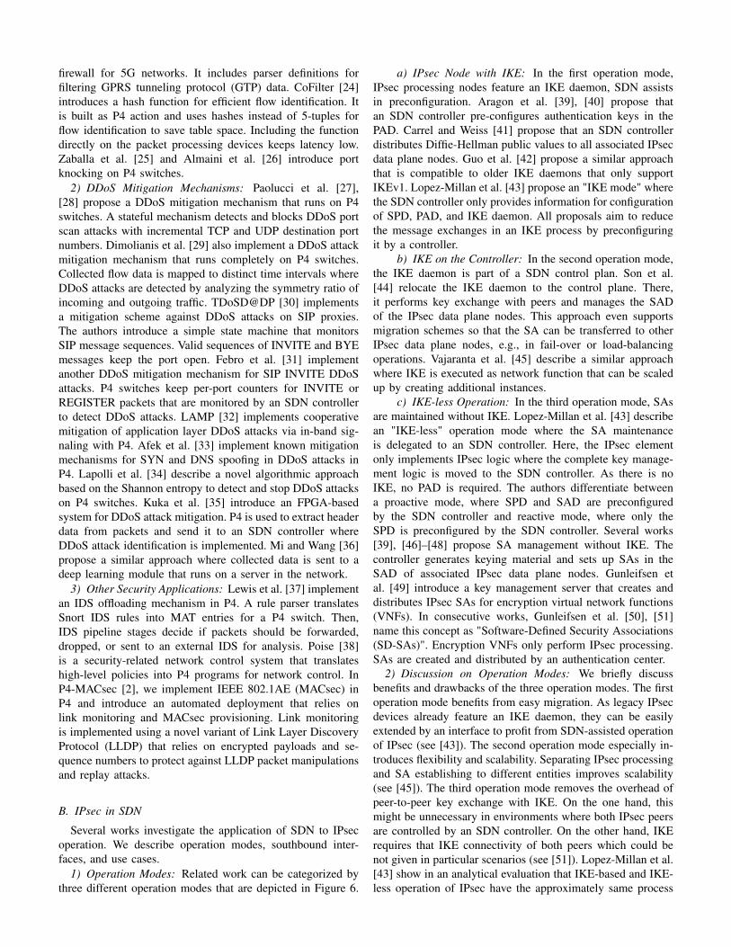
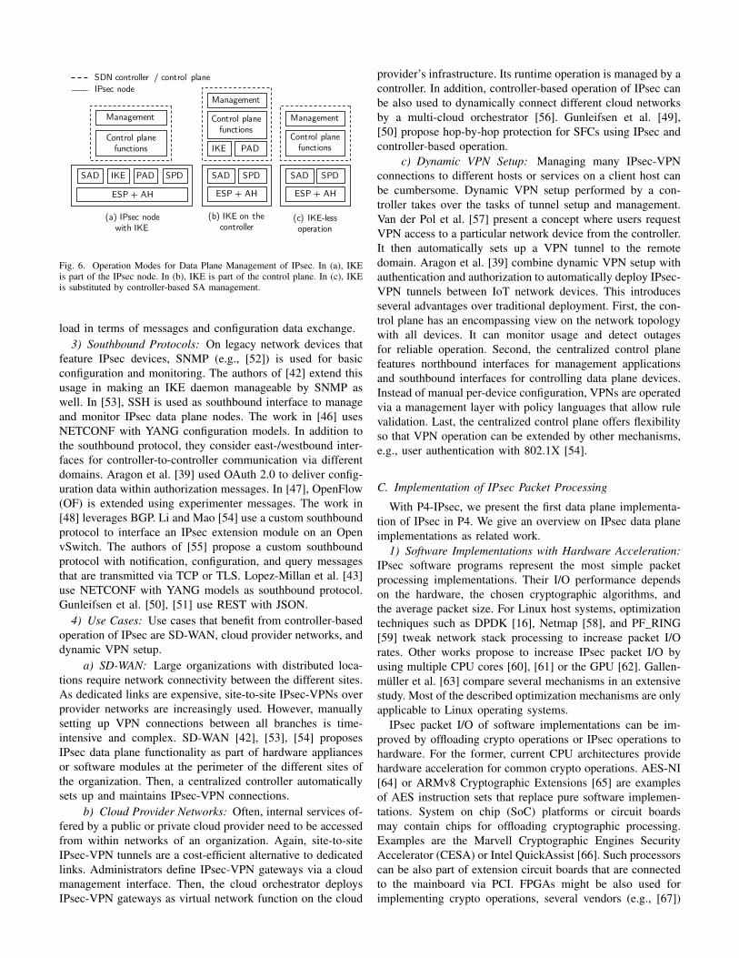
1) Operation Modes: Related work can be categorized bythree different operation modes that are depicted in Figure 6.
a) IPsec Node with IKE: In the first operation mode,IPsec processing nodes feature an IKE daemon, SDN assistsin preconfiguration. Aragon et al. [39], [40] propose thatan SDN controller pre-configures authentication keys in thePAD. Carrel and Weiss [41] propose that an SDN controllerdistributes Diffie-Hellman public values to all associated IPsecdata plane nodes. Guo et al. [42] propose a similar approachthat is compatible to older IKE daemons that only supportIKEv1. Lopez-Millan et al. [43] propose an "IKE mode" wherethe SDN controller only provides information for configurationof SPD, PAD, and IKE daemon. All proposals aim to reducethe message exchanges in an IKE process by preconfiguringit by a controller.
b) IKE on the Controller: In the second operation mode,the IKE daemon is part of a SDN control plan. Son et al.[44] relocate the IKE daemon to the control plane. There,it performs key exchange with peers and manages the SADof the IPsec data plane nodes. This approach even supportsmigration schemes so that the SA can be transferred to otherIPsec data plane nodes, e.g., in fail-over or load-balancingoperations. Vajaranta et al. [45] describe a similar approachwhere IKE is executed as network function that can be scaledup by creating additional instances.
c) IKE-less Operation: In the third operation mode, SAsare maintained without IKE. Lopez-Millan et al. [43] describean "IKE-less" operation mode where the SA maintenanceis delegated to an SDN controller. Here, the IPsec elementonly implements IPsec logic where the complete key manage-ment logic is moved to the SDN controller. As there is noIKE, no PAD is required. The authors differentiate betweena proactive mode, where SPD and SAD are preconfiguredby the SDN controller and reactive mode, where only theSPD is preconfigured by the SDN controller. Several works[39], [46]–[48] propose SA management without IKE. Thecontroller generates keying material and sets up SAs in theSAD of associated IPsec data plane nodes. Gunleifsen etal. [49] introduce a key management server that creates anddistributes IPsec SAs for encryption virtual network functions(VNFs). In consecutive works, Gunleifsen et al. [50], [51]name this concept as "Software-Defined Security Associations(SD-SAs)". Encryption VNFs only perform IPsec processing.SAs are created and distributed by an authentication center.
2) Discussion on Operation Modes: We briefly discussbenefits and drawbacks of the three operation modes. The firstoperation mode benefits from easy migration. As legacy IPsecdevices already feature an IKE daemon, they can be easilyextended by an interface to profit from SDN-assisted operationof IPsec (see [43]). The second operation mode especially in-troduces flexibility and scalability. Separating IPsec processingand SA establishing to different entities improves scalability(see [45]). The third operation mode removes the overhead ofpeer-to-peer key exchange with IKE. On the one hand, thismight be unnecessary in environments where both IPsec peersare controlled by an SDN controller. On the other hand, IKErequires that IKE connectivity of both peers which could benot given in particular scenarios (see [51]). Lopez-Millan et al.[43] show in an analytical evaluation that IKE-based and IKE-less operation of IPsec have the approximately same process
IKE
ESP + AH
Control plane functions
Management
(a) IPsec nodewith IKE
IPsec nodeSDN controller / control plane
SPDSAD PAD
ESP + AH
SPDSAD
IKE PAD
Control plane functions
Management
(b) IKE on the controller
(c) IKE-lessoperation
ESP + AH
SPDSAD
Control plane functions
Management
Fig. 6. Operation Modes for Data Plane Management of IPsec. In (a), IKEis part of the IPsec node. In (b), IKE is part of the control plane. In (c), IKEis substituted by controller-based SA management.
load in terms of messages and configuration data exchange.3) Southbound Protocols: On legacy network devices that
feature IPsec devices, SNMP (e.g., [52]) is used for basicconfiguration and monitoring. The authors of [42] extend thisusage in making an IKE daemon manageable by SNMP aswell. In [53], SSH is used as southbound interface to manageand monitor IPsec data plane nodes. The work in [46] usesNETCONF with YANG configuration models. In addition tothe southbound protocol, they consider east-/westbound inter-faces for controller-to-controller communication via differentdomains. Aragon et al. [39] used OAuth 2.0 to deliver config-uration data within authorization messages. In [47], OpenFlow(OF) is extended using experimenter messages. The work in[48] leverages BGP. Li and Mao [54] use a custom southboundprotocol to interface an IPsec extension module on an OpenvSwitch. The authors of [55] propose a custom southboundprotocol with notification, configuration, and query messagesthat are transmitted via TCP or TLS. Lopez-Millan et al. [43]use NETCONF with YANG models as southbound protocol.Gunleifsen et al. [50], [51] use REST with JSON.
4) Use Cases: Use cases that benefit from controller-basedoperation of IPsec are SD-WAN, cloud provider networks, anddynamic VPN setup.
a) SD-WAN: Large organizations with distributed loca-tions require network connectivity between the different sites.As dedicated links are expensive, site-to-site IPsec-VPNs overprovider networks are increasingly used. However, manuallysetting up VPN connections between all branches is time-intensive and complex. SD-WAN [42], [53], [54] proposesIPsec data plane functionality as part of hardware appliancesor software modules at the perimeter of the different sites ofthe organization. Then, a centralized controller automaticallysets up and maintains IPsec-VPN connections.
b) Cloud Provider Networks: Often, internal services of-fered by a public or private cloud provider need to be accessedfrom within networks of an organization. Again, site-to-siteIPsec-VPN tunnels are a cost-efficient alternative to dedicatedlinks. Administrators define IPsec-VPN gateways via a cloudmanagement interface. Then, the cloud orchestrator deploysIPsec-VPN gateways as virtual network function on the cloud
provider’s infrastructure. Its runtime operation is managed by acontroller. In addition, controller-based operation of IPsec canbe also used to dynamically connect different cloud networksby a multi-cloud orchestrator [56]. Gunleifsen et al. [49],[50] propose hop-by-hop protection for SFCs using IPsec andcontroller-based operation.
c) Dynamic VPN Setup: Managing many IPsec-VPNconnections to different hosts or services on a client host canbe cumbersome. Dynamic VPN setup performed by a con-troller takes over the tasks of tunnel setup and management.Van der Pol et al. [57] present a concept where users requestVPN access to a particular network device from the controller.It then automatically sets up a VPN tunnel to the remotedomain. Aragon et al. [39] combine dynamic VPN setup withauthentication and authorization to automatically deploy IPsec-VPN tunnels between IoT network devices. This introducesseveral advantages over traditional deployment. First, the con-trol plane has an encompassing view on the network topologywith all devices. It can monitor usage and detect outagesfor reliable operation. Second, the centralized control planefeatures northbound interfaces for management applicationsand southbound interfaces for controlling data plane devices.Instead of manual per-device configuration, VPNs are operatedvia a management layer with policy languages that allow rulevalidation. Last, the centralized control plane offers flexibilityso that VPN operation can be extended by other mechanisms,e.g., user authentication with 802.1X [54].
C. Implementation of IPsec Packet Processing
With P4-IPsec, we present the first data plane implementa-tion of IPsec in P4. We give an overview on IPsec data planeimplementations as related work.
1) Software Implementations with Hardware Acceleration:IPsec software programs represent the most simple packetprocessing implementations. Their I/O performance dependson the hardware, the chosen cryptographic algorithms, andthe average packet size. For Linux host systems, optimizationtechniques such as DPDK [16], Netmap [58], and PF_RING[59] tweak network stack processing to increase packet I/Orates. Other works propose to increase IPsec packet I/O byusing multiple CPU cores [60], [61] or the GPU [62]. Gallen-müller et al. [63] compare several mechanisms in an extensivestudy. Most of the described optimization mechanisms are onlyapplicable to Linux operating systems.
IPsec packet I/O of software implementations can be im-proved by offloading crypto operations or IPsec operations tohardware. For the former, current CPU architectures providehardware acceleration for common crypto operations. AES-NI[64] or ARMv8 Cryptographic Extensions [65] are examplesof AES instruction sets that replace pure software implemen-tations. System on chip (SoC) platforms or circuit boardsmay contain chips for offloading cryptographic processing.Examples are the Marvell Cryptographic Engines SecurityAccelerator (CESA) or Intel QuickAssist [66]. Such processorscan be also part of extension circuit boards that are connectedto the mainboard via PCI. FPGAs might be also used forimplementing crypto operations, several vendors (e.g., [67])
supply implementations of cryptographic algorithms as pro-gram cores. For the latter, IPsec hardware accellerators areavailable as ASIC [68], [69], NPU [70], [71], accelleratedprocessing unit (APU) [72], or FPGA [73], [74].
2) Hardware Implementations: Proprietary IPsec hardwareconcentrators, e.g., as sold by Cisco or Juniper, are optimizedfor high IPsec I/O rates and, therefore, might implement alarger degree of the overall IPsec processing operations inhardware (e.g., ASICs). Due to their disclosed architecturaldetails, we cannot get insight into technical details. In addition,encompassing IPsec implementations for FPGAs exist [75],[76] where only SPD and SAD are managed by an SDNcontroller.
3) Implementations on Programmable Data Planes: Forprogrammable data planes, in 2016, a Xilinx employee re-ported on the P4-Development mailing list [77] that IPsec wassuccessfully implemented in PX [78], a high-level domain-specific programming language for programmable data planes.Crypto primitives are not expressed in the language, but byan extern mechanism similar to P4’s externs. The authorsreport that the crypto primitives were programmed as RegisterTransfer Level (RTL) designs targeting FPGAs. The authorsreport that the principle should be exactly the same for P4,but it was not ported so far.
IV. CONCEPT
We describe the concept of P4-IPsec. We give an overview,discuss design choices, and describe its data plane and controlplane in detail.
A. Overview
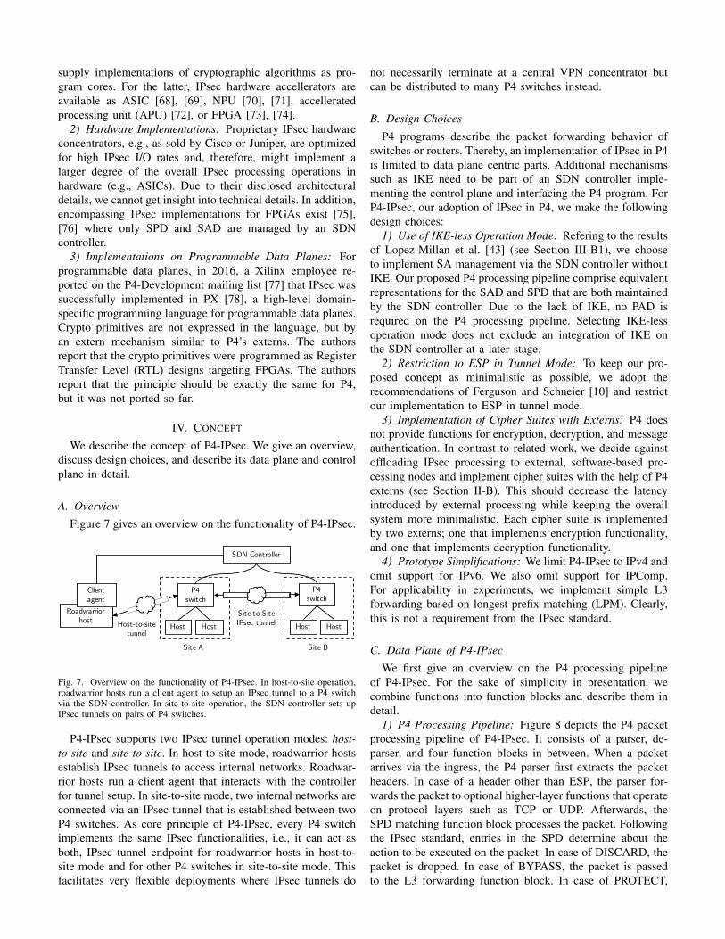
Figure 7 gives an overview on the functionality of P4-IPsec.
Roadwarrior host Host-to-site
tunnel
P4 switch
Host
P4 switch
HostSite-to-SiteIPsec tunnel
SDN Controller
Site A Site B
Host Host
Client agent
Fig. 7. Overview on the functionality of P4-IPsec. In host-to-site operation,roadwarrior hosts run a client agent to setup an IPsec tunnel to a P4 switchvia the SDN controller. In site-to-site operation, the SDN controller sets upIPsec tunnels on pairs of P4 switches.
P4-IPsec supports two IPsec tunnel operation modes: host-to-site and site-to-site. In host-to-site mode, roadwarrior hostsestablish IPsec tunnels to access internal networks. Roadwar-rior hosts run a client agent that interacts with the controllerfor tunnel setup. In site-to-site mode, two internal networks areconnected via an IPsec tunnel that is established between twoP4 switches. As core principle of P4-IPsec, every P4 switchimplements the same IPsec functionalities, i.e., it can act asboth, IPsec tunnel endpoint for roadwarrior hosts in host-to-site mode and for other P4 switches in site-to-site mode. Thisfacilitates very flexible deployments where IPsec tunnels do
not necessarily terminate at a central VPN concentrator butcan be distributed to many P4 switches instead.
B. Design Choices
P4 programs describe the packet forwarding behavior ofswitches or routers. Thereby, an implementation of IPsec in P4is limited to data plane centric parts. Additional mechanismssuch as IKE need to be part of an SDN controller imple-menting the control plane and interfacing the P4 program. ForP4-IPsec, our adoption of IPsec in P4, we make the followingdesign choices:
1) Use of IKE-less Operation Mode: Refering to the resultsof Lopez-Millan et al. [43] (see Section III-B1), we chooseto implement SA management via the SDN controller withoutIKE. Our proposed P4 processing pipeline comprise equivalentrepresentations for the SAD and SPD that are both maintainedby the SDN controller. Due to the lack of IKE, no PAD isrequired on the P4 processing pipeline. Selecting IKE-lessoperation mode does not exclude an integration of IKE onthe SDN controller at a later stage.
2) Restriction to ESP in Tunnel Mode: To keep our pro-posed concept as minimalistic as possible, we adopt therecommendations of Ferguson and Schneier [10] and restrictour implementation to ESP in tunnel mode.
3) Implementation of Cipher Suites with Externs: P4 doesnot provide functions for encryption, decryption, and messageauthentication. In contrast to related work, we decide againstoffloading IPsec processing to external, software-based pro-cessing nodes and implement cipher suites with the help of P4externs (see Section II-B). This should decrease the latencyintroduced by external processing while keeping the overallsystem more minimalistic. Each cipher suite is implementedby two externs; one that implements encryption functionality,and one that implements decryption functionality.
4) Prototype Simplifications: We limit P4-IPsec to IPv4 andomit support for IPv6. We also omit support for IPComp.For applicability in experiments, we implement simple L3forwarding based on longest-prefix matching (LPM). Clearly,this is not a requirement from the IPsec standard.
C. Data Plane of P4-IPsec
We first give an overview on the P4 processing pipelineof P4-IPsec. For the sake of simplicity in presentation, wecombine functions into function blocks and describe them indetail.
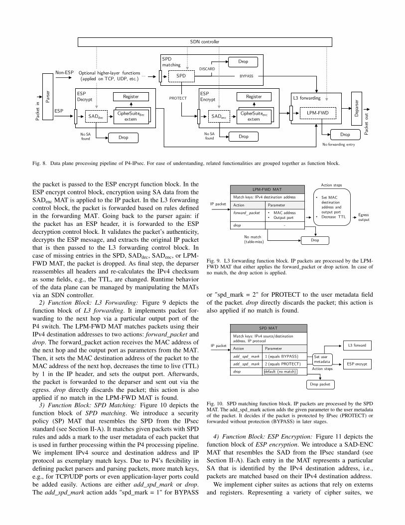
1) P4 Processing Pipeline: Figure 8 depicts the P4 packetprocessing pipeline of P4-IPsec. It consists of a parser, de-parser, and four function blocks in between. When a packetarrives via the ingress, the P4 parser first extracts the packetheaders. In case of a header other than ESP, the parser for-wards the packet to optional higher-layer functions that operateon protocol layers such as TCP or UDP. Afterwards, theSPD matching function block processes the packet. Followingthe IPsec standard, entries in the SPD determine about theaction to be executed on the packet. In case of DISCARD, thepacket is dropped. In case of BYPASS, the packet is passedto the L3 forwarding function block. In case of PROTECT,
Non-ESPSPD
Drop
Pars
er
Dep
arse
r
CipherSuitedecexternSADdec
ESPDecrypt
ESP
No SA found
Register
CipherSuiteencexternSADenc
ESPEncrypt RegisterPROTECT
BYPASS
No SA found Drop
DISCARDOptional higher-layer functions (applied on TCP, UDP, etc.)
Drop
SDN controller
LPM-FWD
L3 forwarding
…
SPDmatching
Pack
et in
Pack
et o
ut
Drop
No forwarding entry
Fig. 8. Data plane processing pipeline of P4-IPsec. For ease of understanding, related functionalities are grouped together as function block.
the packet is passed to the ESP encrypt function block. In theESP encrypt control block, encryption using SA data from theSADenc MAT is applied to the IP packet. In the L3 forwardingcontrol block, the packet is forwarded based on rules definedin the forwarding MAT. Going back to the parser again: ifthe packet has an ESP header, it is forwarded to the ESPdecryption control block. It validates the packet’s authenticity,decrypts the ESP message, and extracts the original IP packetthat is then passed to the L3 forwarding control block. Incase of missing entries in the SPD, SADdec, SADenc, or LPM-FWD MAT, the packet is dropped. As final step, the deparserreassembles all headers and re-calculates the IPv4 checksumas some fields, e.g., the TTL, are changed. Runtime behaviorof the data plane can be managed by manipulating the MATsvia an SDN controller.
2) Function Block: L3 Forwarding: Figure 9 depicts thefunction block of L3 forwarding. It implements packet for-warding to the next hop via a particular output port of theP4 switch. The LPM-FWD MAT matches packets using theirIPv4 destination addresses to two actions: forward_packet anddrop. The forward_packet action receives the MAC address ofthe next hop and the output port as parameters from the MAT.Then, it sets the MAC destination address of the packet to theMAC address of the next hop, decreases the time to live (TTL)by 1 in the IP header, and sets the output port. Afterwards,the packet is forwarded to the deparser and sent out via theegress. drop directly discards the packet; this action is alsoapplied if no match in the LPM-FWD MAT is found.
3) Function Block: SPD Matching: Figure 10 depicts thefunction block of SPD matching. We introduce a securitypolicy (SP) MAT that resembles the SPD from the IPsecstandard (see Section II-A). It matches given packets with SPDrules and adds a mark to the user metadata of each packet thatis used in further processing within the P4 processing pipeline.We implement IPv4 source and destination address and IPprotocol as exemplary match keys. Due to P4’s flexibility indefining packet parsers and parsing packets, more match keys,e.g., for TCP/UDP ports or even application-layer ports couldbe added easily. Actions are either add_spd_mark or drop.The add_spd_mark action adds "spd_mark = 1" for BYPASS
LPM-FWD MAT
Match keys: IPv4 destination address
Action Parameter
forward_packet • MAC address• Output port
drop -
Egressoutput
• Set MAC destination address and output port
• Decrease TTL
Action steps
DropNo match (table-miss)
IP packet
Fig. 9. L3 forwarding function block. IP packets are processed by the LPM-FWD MAT that either applies the forward_packet or drop action. In case ofno match, the drop action is applied.
or "spd_mark = 2" for PROTECT to the user metadata fieldof the packet. drop directly discards the packet; this action isalso applied if no match is found.
L3 forward
ESP encrypt
SPD MAT
Match keys: IPv4 source/destination address, IP protocol
Action Parameter
add_spd_mark 1 (equals BYPASS)
add_spd_mark 2 (equals PROTECT)
drop
Drop packet
IP packet
Set user metadata
Action stepsdefault (no match)
Fig. 10. SPD matching function block. IP packets are processed by the SPDMAT. The add_spd_mark action adds the given parameter to the user metadataof the packet. It decides if the packet is protected by IPsec (PROTECT) orforwarded without protection (BYPASS) in later stages.
4) Function Block: ESP Encryption: Figure 11 depicts thefunction block of ESP encryption. We introduce a SAD-ENCMAT that resembles the SAD from the IPsec standard (seeSection II-A). Each entry in the MAT represents a particularSA that is identified by the IPv4 destination address, i.e.,packets are matched based on their IPv4 destination address.
We implement cipher suites as actions that rely on externsand registers. Representing a variety of cipher suites, we
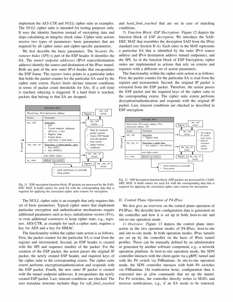
implement the AES-CTR and NULL cipher suite as examples.The NULL cipher suite is intended for testing purposes only.It uses the identity function instead of encrypting data andskips calculating an integrity check value. Cipher suite actionsreceive two types of parameters: basic parameters that arerequired by all cipher suites and cipher-specific parameters.
We first describe the basic parameters. The Security Pa-rameter Index (SPI) is part of the ESP header. It identifies theSA. The tunnel endpoint addresses (IPv4 source/destinationaddress) identify the source and destination of the IPsec tunnel.Both are part of the new outer IPv4 header that encapsulatesthe ESP frame. The register index points to a particular indexthat holds the packet counter for the particular SA used by thecipher suite extern. Packet limits declare timeout conditionsin terms of packet count thresholds for SAs. If a soft limitis reached, rekeying is triggered. If a hard limit is reached,packets that belong to that SA are dropped.
SAD-ENC MAT
Match keys: IPv4 destination address
Action Parameter
enc_null Base data• SPI• Tunnel endpoint addresses
(IPv4 src + dst)• Register index• Packet limits
(soft limit + hard limit)
enc_aes_ctr Base data + cipher-specific data• Key (AES)• Key (HMAC)
… more cipher suites …
sa_miss
enc_nullaction
enc_nullextern
enc_aes_ctraction
Register
IP p
acke
t
default (no match)enc_aes_ctr
externRegister
• Read & increment packet counter
• Create ESP header and add payload from extern
• Apply timeout conditions
• Send notification to controller• Drop packet
Fig. 11. ESP encryption function block. IP packets are processed by the SAD-ENC MAT. It holds entries for each SA with the corresponding data that isrequired for applying the associated cipher suite externs for encryption.
The NULL cipher suite is an example that only requires thisset of basic parameters. Typical cipher suites that implementparticular encryption and authentication mechanisms requireadditional parameters such as keys, initialization vectors (IVs),or even additional constructs to keep cipher state, e.g., regis-ters. AES-CTR, as example for such a cipher suite, requires akey for AES and a key for HMAC.
The functionality within the cipher suite action is as follows.First, the packet counter for the particular SA is read from theregister and incremented. Second, an ESP header is createdwith the SPI and sequence number of the packet. For thecreation of the ESP packet, the action passes the original IPpacket, the newly created ESP header, and required keys ofthe cipher suite to the corresponding extern. The cipher suiteextern performs encryption/authentication and responds withthe ESP packet. Fourth, the new outer IP packet is createdwith the tunnel endpoint addresses. It encapsulates the newlycreated ESP packet. Last, timeout conditions are checked. Theuser metadata structure includes flags for soft_limit_reached
and hard_limit_reached that are set in case of matchingconditions.
5) Function Block: ESP Decryption: Figure 12 depicts thefunction block of ESP decryption. We introduce the SAD-DEC MAT that resembles the decryption SAD from the IPsecstandard (see Section II-A). Each entry in the MAT representsa particular SA that is identified by the outer IPv4 sourceaddress and IPv4 destination address (tunnel endpoints), andthe SPI. As in the function block of ESP Encryption, ciphersuites are implemented as actions that rely on externs andregisters with a different set of action parameters.
The functionality within the cipher suite action is as follows.First, the packet counter for the particular SA is read from theregister and incremented. Second, the original IP packet isextracted from the ESP packet. Therefore, the action passesthe ESP packet and the required keys of the cipher suite tothe corresponding extern. The cipher suite extern performsdecryption/authentication and responds with the original IPpacket. Last, timeout conditions are checked as described inESP encryption.
ESP
pack
etSAD-DEC MAT
Match keys: IPv4 source address, IPv4 destination address, SPI
Action Parameter
dec_null Base data• Register index
dec_aes_ctr Base data + cipher data• Key (cipher) + key (HMAC)
… more cipher suites …
sa_miss
• Send notification to controller• Drop packet
dec_aes_ctraction
dec_aes_ctrextern
Register
dec_nullaction
dec_nullexternRegister
default (no match)
• Get original IP packet from extern
• Read & increment packet counter
Fig. 12. ESP decryption function block. ESP packets are processed by a SAD-DEC MAT. It holds entries for each SA with the corresponding data that isrequired for applying the associated cipher suite externs for decryption.
D. Control Plane Operation of P4-IPsec
We first give an overview on the control plane operation ofP4-IPsec. We describe how configuration data is generated onthe controller and how it is set up in both, host-to-site andsite-to-site operation mode.
1) Overview: Figure 13 depicts the control plane inter-action in the two operation modes of P4-IPsec, host-to-siteand site-to-site mode. In both operation modes, IPsec tunnelsare set up by the controller on the basis of IPsec tunnelprofiles. Those can be manually defined by an administratoror generated by another software component, e.g., a networkoperation platform. In host-to-site operation mode, the SDNcontroller interacts with the client agent via a gRPC tunnel andwith the P4 switch via P4Runtime. In site-to-site operationmode, the SDN controller interacts with both P4 switchesvia P4Runtime. On roadwarrior hosts, configuration data isconverted into ip xfrm commands that set up the tunnel.For P4 switches, the controller directly writes to MATs andreceives notifications, e.g., if an SA needs to be renewed,
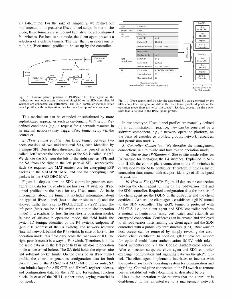
via P4Runtime. For the sake of simplicity, we restrict ourimplementation to proactive IPsec tunnel setup. In site-to-sitemode, IPsec tunnels are set up and kept alive for all configuredP4 switches. For host-to-site mode, the client agent presents aselection of available tunnels. The user then can select one ormultiple IPsec tunnel profiles to be set up by the controller.
P4switch
P4switch
Roadwarrior host
Site A Site B
SDN controller
P4Runtime P4Runtime
gRPCIPsec tunnel
profile
IPsec IPsec
Client agent
Fig. 13. Control plane operation in P4-IPsec. The client agent on theroadwarrior host holds a control channel via gRPC to the SDN controller. P4switches are connected via P4Runtime. The SDN controller includes IPsectunnel profiles with configuration data for tunnel setup and management.
This mechanism can be extended or substituted by moresophisticated approaches such as on-demand VPN setup. Pre-defined conditions (e.g., a request for a network resource inan internal network) may trigger IPsec tunnel setup via thecontroller.
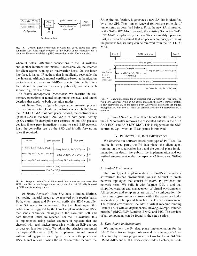
2) IPsec Tunnel Profiles: An IPsec tunnel between twopeers consists of two unidirectional SAs, each identified bya unique SPI. Due to their direction, the first peer of an SA iscalled "left" where the second peer of the SA is called "right".We denote the SA from the left to the right peer as SPIi andthe SA from the right to the left peer as SPIj, respectively.Each SA requires two MAT entries: one for encrypting ESPpackets in the SAD-ENC MAT and one for decrypting ESPpackets in the SAD-DEC MAT.
Figure 14 depicts how the SDN controller generates con-figuration data for the roadwarrior hosts or P4 switches. IPsectunnel profiles are the basis for any IPsec tunnel. As basicinformation about the tunnel, it includes information aboutthe type of IPsec tunnel (host-to-site or site-to-site) and theallowed traffic that is set to PROTECTED via SPD rules. Theleft peer (first) can be a P4 switch (in site-to-site operationmode) or a roadwarrior host (in host-to-site operation mode).In case of site-to-site operation mode, this field holds theswitch ID (unique identifier of the P4 switch), endpoint IP(public IP address of the P4 switch), and network resource(internal network behind the P4 switch). In case of host-to-siteoperation mode, this field only holds the roadwarrior ID. Theright peer (second) is always a P4 switch. Therefore, it holdsthe same data as in the left peer field in site-to-site operationmode as described before. The SA field holds the cipher suiteand soft/hard packet limits. On the basis of an IPsec tunnelprofile, the controller generates configuration data for bothSAs. In case of the AES-CTR-HMAC-MD5 cipher suite, SAdata inludes keys for AES-CTR and HMAC, register indexes,and configuration data for the SPD and forwarding functionblock. In case of the NULL cipher suite, keying material isnot needed.
Type Site-to-site
Allowed traffic ICMP
Left(first peer)
Site-to-site
Switch ID sw-1
Endpoint IP 10.0.1.1
Network resource 192.168.1.0/24
Host-to-site
Roadwarrior ID rw-1
Right(second peer)
Switch ID sw-2
Endpoint IP 10.0.2.1
Network resource 192.168.2.0/24
SA Cipher suite AES-CTR-HMAC-MD5
Soft packet limit 10
Hard packet limit 20
SA (SPIi)
Key(AES-CTR)
Register
IPsec tunnel profiles(manually defined or automatically generated)
SDN
con
trol
ler
Key(HMAC)
SPD + forwarding
SA (SPIj)
Key(AES-CTR)
Register
Key(HMAC)
SPD + forwarding
SA data generated by the SDN controller
Fig. 14. IPsec tunnel profiles with the associated SA data generated by theSDN controller. Configuration data in the IPsec tunnel profiles depends on theoperation mode (host-to-site or site-to-site). SA data depends on the ciphersuite that is defined in the IPsec tunnel profile.
In our prototype, IPsec tunnel profiles are manually definedby an administrator. In practice, they can be generated by asoftware component, e.g., a network operation platform, onthe basis of user/device profiles, groups, network resources,and permission models.
3) Controller Connection: We describe the managementconnections in site-to-site and host-to-site operation mode.
a) Site-to-Site (P4Runtime): Site-to-site mode relies onP4Runtime for managing the P4 switches. Explained in Sec-tion II-B3, the control plane connection to the P4 switches isestablished by the SDN controller. Therefore, it holds a list ofconnection data (name, address, port identity) of all assignedP4 switches.
b) Host-to-Site (gRPC): Figure 15 depicts the connectionbetween the client agent running on the roadwarrior host andthe SDN controller. Required configuration data for the start ofthe client agent are the FQDN of the controller and the clientcertificate. At start, the client agents establishes a gRPC tunnelto the SDN controller. The gRPC tunnel is protected withSSL/TLS, i.e., the client agent and SDN controller performa mutual authentication using certificates and establish anencrypted connection. Certificates can be created and deployedto all roadwarrior hosts running the client agent and the SDNcontroller with a public key infrastructure (PKI). Roadwarriorhost access can be removed by simply revoking the asso-ciated client certificate. In addition, gRPC provides supportfor optional multi-factor authentication (MFA) with token-based authentication via the Google Authenticator service.After connection setup, the client agent and SDN controllerexchange configuration and signaling data via the gRPC tun-nel. The client agent implements interfaces to interact withthe roadwarrior host’s operating system for configuration andsignaling. Control plane connection to the P4 switch as remotepeer is established with P4Runtime as described before.
Host-to-site operation mode requires that the controller isdual-homed. It has an interface to a management network
Client agent
SDN controller
Configuration
Roadwarrior host
gRPC connection
Authenticated +Encrypted
Controller FQDN
Client certificate
OS
Fig. 15. Control plane connection between the client agent and SDNcontroller. The client agent depends on the FQDN of the controller and aclient certificate to establish a gRPC connection to the SDN controller.
where it holds P4Runtime connections to the P4 switchesand another interface that makes it accessible via the Internetfor client agents running on roadwarrior hosts. On the latterinterface, it has an IP address that is publically reachable viathe Internet. Although mutual certificate-based authenticationprotects against malicious P4-IPsec agents, this public inter-face should be protected as every publically available webservice, e.g., with a firewall.
4) Tunnel Management Operations: We describe the ele-mentary operations of tunnel setup, tunnel renewal, and tunneldeletion that apply to both operation modes.
a) Tunnel Setup: Figure 16 depicts the three-step processof IPsec tunnel setup. First, the controller sets up both SAs inthe SAD-DEC MATs of both peers. Second, the controller setsup both SAs in the SAD-ENC MATs of both peers. Settingup SA entries for decryption first ensures that no ESP packetsget lost if one peer immediately starts to send ESP packets.Last, the controller sets up the SPD and installs forwardingrules if required.
SDN controllerLeft peer Right peer
IPsec SA (SPIj)IPsec SA (SPIi)
Setup SA (SPIj, SAD-DEC)Setup SA (SPIi, SAD-DEC)
Setup SA (SPIi, SAD-ENC) Setup SA (SPIj, SAD-ENC)
Setup SPD + forwardingSetup SPD + forwarding
I
II
III
Fig. 16. Setup procedure for a bidirectional IPsec tunnel on two peers. TheSDN controller sets up decryption and encryption for both SAs (II) followedby SPD and forwarding entries.
b) Tunnel Renewal: IPsec SAs have a limited lifetime,i.e., keying material needs to be renewed on a regular basis.Both, client agent and P4 switch notify the SDN controllerif an SA needs to be renewed. For the client agent, thisnotification is triggered by the kernel implementation of IPsecthat sends expiration messages in the case that soft andhard timeout limits are reached. For the P4 switches, thisis implemented using packet counters in registers that arechecked with each packet processing within an ESP encryptor decrypt function block. We adopt the principle presentedby Lopez-Millan et al. [43] that implements tunnel renewalwithout risking packet loss. Figure 17 depicts the process ofIPsec tunnel renewal. When the SDN controller received the
SA expire notification, it generates a new SA that is identifiedby a new SPI. Then, tunnel renewal follows the principle oftunnel setup as described before. First, the new SA is installedin the SAD-DEC MAT. Second, the existing SA in the SAD-ENC MAT is replaced by the new SA via a modify operation.Last, as it can be ensured that no packets are encrypted usingthe previous SA, its entry can be removed from the SAD-DECMAT.
SDN controllerPeer 1 Peer 2
IPsec SA (SPIi)
SA expireSetup SA (SPIi+1, SAD-DEC)
Modify SA (SPIi, SPIi+1, SAD-ENC)
IPsec SA (SPIi+1)
Delete SA(SPIi, SAD-DEC)
Notification from P4 switch or client agent
Fig. 17. Renewal procedure for an unidirectional SA within an IPsec tunnel ontwo peers. After receiving an SA expire message, the SDN controller installsa new decryption SA on the remote peer. Afterwards, it replaces the expiredencryption SA with new SA data. As cleanup step, the old decryption SA isremoved.
c) Tunnel Deletion: If an IPsec tunnel should be deleted,the SDN controller removes the associated entries in the SPD,SAD-ENC, and SAD-DEC MAT. This is triggered on the SDNcontroller, e.g., when an IPsec profile is removed.
V. PROTOTYPICAL IMPLEMENTATION
We describe our software-based prototype of P4-IPsec. Weoutline its three parts, the P4 data plane, the client agentrunning on the roadwarrior host, and the control plane imple-mentation, in detail. We publish the implementation and ourtestbed environment under the Apache v2 license on GitHub[1].
A. Testbed Environment
Our prototypical implementation of P4-IPsec includes asoftwarized testbed environment. We use Mininet to createnetwork topologies that consist of BMv2 P4 switches andnetwork hosts. We build it with Vagrant [79], a tool thatsimplifies creation and management of virtual environments.All resources and setup steps are part of a configuration file.Executing vagrant up in a console within the repository folderautomatically sets up and launches the testbed environment.The testbed environment includes a virtual machine runningUbuntu 16.04 with all dependencies: libyang, sysrepo, mininet,protobuf, gRPC, PI/P4Runtime, BMv2, and P4C. The versionsof all components can be found in the setup scripts.
B. Data Plane Implementation
We implement the P4 data plane implementation for theBMv2 P4 software target. We extend its simple_switch ar-chitecture by externs programmed in C++ for the AES-CTR-HMAC-MD5 and NULL IPsec cipher suites. Each cipher suite
is implemented by two externs, one for encryption and one fordecryption. For AES-CTR-HMAC-MD5, we use OpenSSL toapply AES-CTR for encryption/decryption and HMAC-MD5for packet authentication. We implement the P4 processingpipeline as P416 program. It relies on the cipher suite externsand uses registers to store packet counters for the SAs. Werun the P4 program on our extended simple_switch P4 target.We encapsulate our modified simple_switch P4 target withinthe simple_switch_grpc P4 target so that P4Runtime API canbe used for interaction with the SDN controller.
C. Client Agent
We implement the client agent as Python 3.6 command linetool for Linux hosts. We integrate a gRPC client using thegRPC library [80] as interface to the SDN controller. For IPsectunnel setup, the client agent translates configuration data fromthe SDN controller into particular XFRM commands from theiproute2 tool to configure IPsec on the roadwarrior host. Inaddition, it sets up IP routes for routing IP traffic via the IPsectunnel. Received and applied configuration data is cached sothat proper teardown configuration can be applied in case oftunnel shutdown. We implement rekeying with the help ofNetlink [81]. The client agent monitors Netlink messages bylistening on the corresponding Netlink socket and binding tothe XFRMNLGRP_EXPIRE address so that XFRM Expiremessages can be received. When receiving an XFRM Expiremessage, it extracts parameters such as SPI and IP addressesof the tunnel endpoints. To initiate rekeying, the tunnel sourceand destination address and SPI are put into a queue forprocessing in the main class.
D. SDN Controller
We implement the controller as command line tool inPython 2.7. We use the p4runtime_lib [20] to integrate theinterface to the P4 switch and the gRPC library to integratethe interface to the client agent. The controller features asimple command line interface (CLI) for development andtesting purposes that displays information about all activeIPsec tunnels. P4Runtime and p4runtime_lib facilitate easyimplementation of individual controllers for prototypes. Nev-ertheless, those functions could be also integrated into existingSDN controllers such as ONOS or OpenDaylight.
VI. PERFORMANCE EVALUATION WITH THE SOFTWARESWITCH BMV2
We describe the test environment and report experimentresults performed with the P4-IPsec software prototype intro-duced in Section V.
A. Methodology
We conduct the performance experiments in the testbedenvironment presented in Section V-A. The testbed runs on aLenovo Thinkpad T480s (Intel i5-8250U CPU, 16 GB RAM)with Manjaro Linux. The Vagrant file in the repository in-cludes the version numbers of all software components fromthe testbed environment.
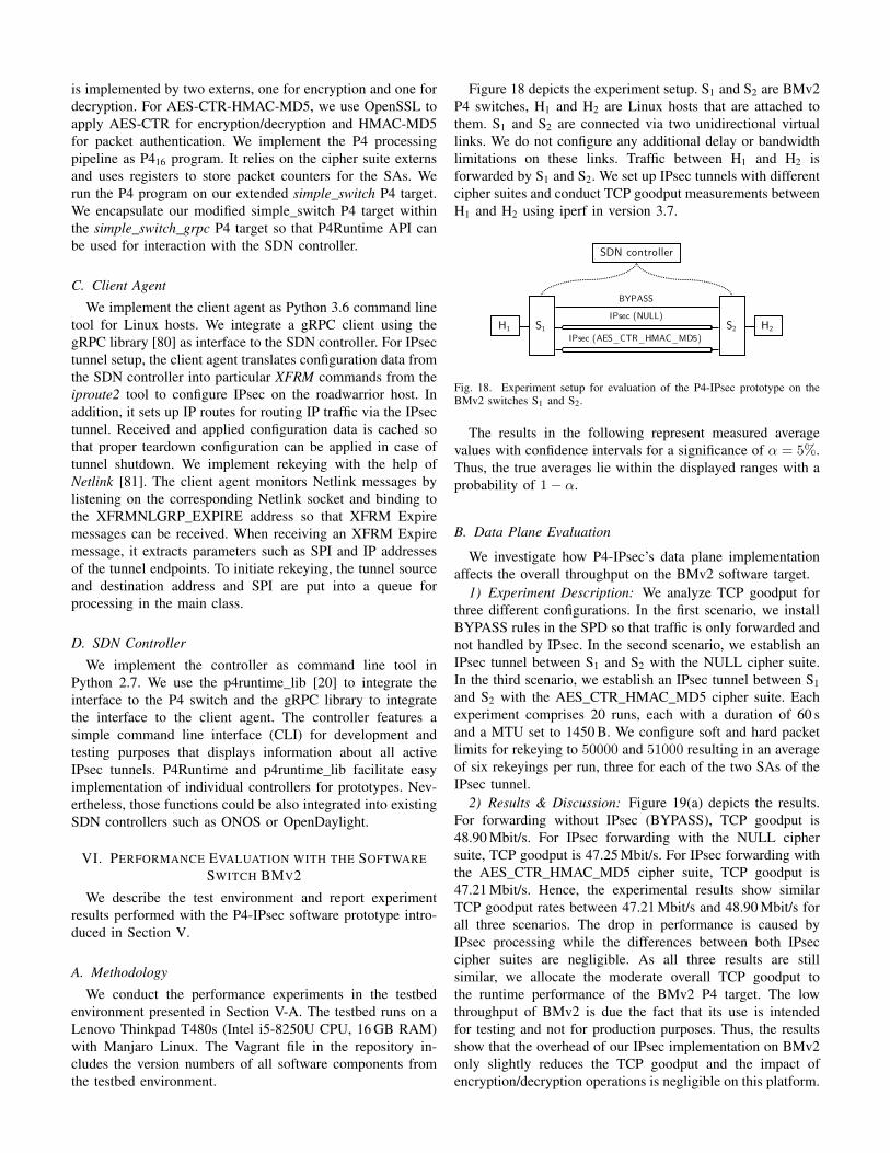
Figure 18 depicts the experiment setup. S1 and S2 are BMv2P4 switches, H1 and H2 are Linux hosts that are attached tothem. S1 and S2 are connected via two unidirectional virtuallinks. We do not configure any additional delay or bandwidthlimitations on these links. Traffic between H1 and H2 isforwarded by S1 and S2. We set up IPsec tunnels with differentcipher suites and conduct TCP goodput measurements betweenH1 and H2 using iperf in version 3.7.
S1 S2
SDN controller
BYPASS
H2IPsec (NULL)
IPsec (AES_CTR_HMAC_MD5)H1
Fig. 18. Experiment setup for evaluation of the P4-IPsec prototype on theBMv2 switches S1 and S2.
The results in the following represent measured averagevalues with confidence intervals for a significance of α = 5%.Thus, the true averages lie within the displayed ranges with aprobability of 1− α.
B. Data Plane Evaluation
We investigate how P4-IPsec’s data plane implementationaffects the overall throughput on the BMv2 software target.
1) Experiment Description: We analyze TCP goodput forthree different configurations. In the first scenario, we installBYPASS rules in the SPD so that traffic is only forwarded andnot handled by IPsec. In the second scenario, we establish anIPsec tunnel between S1 and S2 with the NULL cipher suite.In the third scenario, we establish an IPsec tunnel between S1and S2 with the AES_CTR_HMAC_MD5 cipher suite. Eachexperiment comprises 20 runs, each with a duration of 60 sand a MTU set to 1450 B. We configure soft and hard packetlimits for rekeying to 50000 and 51000 resulting in an averageof six rekeyings per run, three for each of the two SAs of theIPsec tunnel.
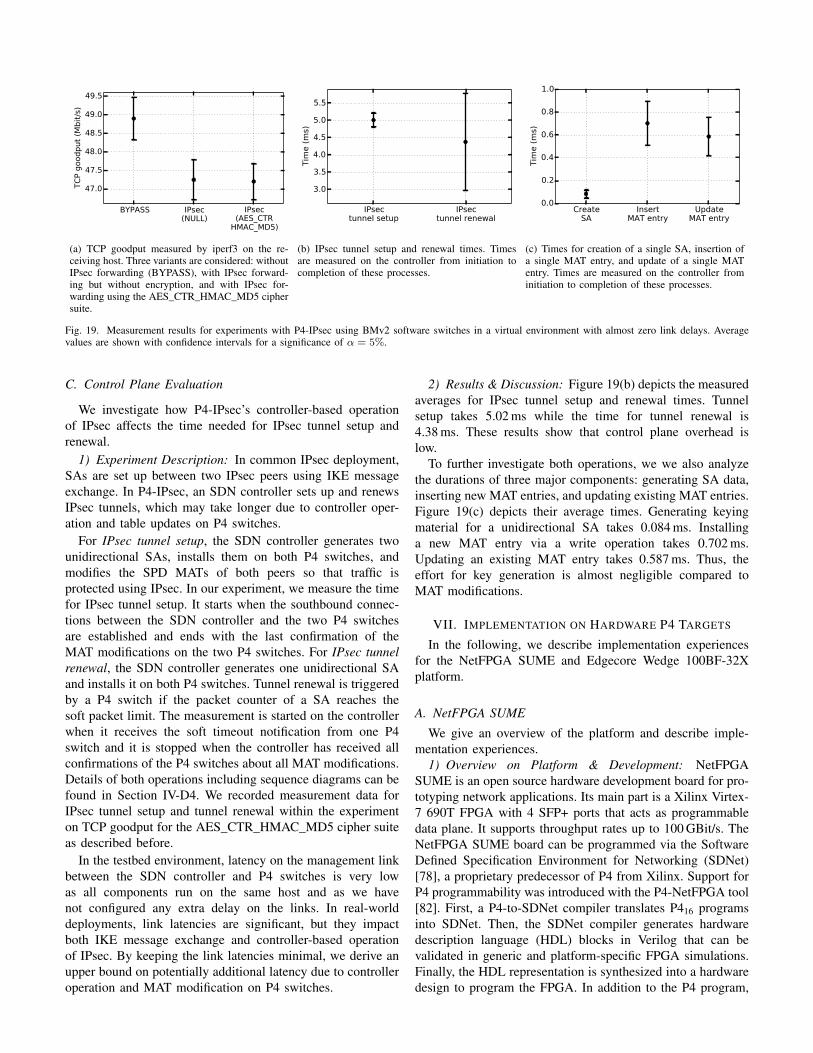
2) Results & Discussion: Figure 19(a) depicts the results.For forwarding without IPsec (BYPASS), TCP goodput is48.90 Mbit/s. For IPsec forwarding with the NULL ciphersuite, TCP goodput is 47.25 Mbit/s. For IPsec forwarding withthe AES_CTR_HMAC_MD5 cipher suite, TCP goodput is47.21 Mbit/s. Hence, the experimental results show similarTCP goodput rates between 47.21 Mbit/s and 48.90 Mbit/s forall three scenarios. The drop in performance is caused byIPsec processing while the differences between both IPseccipher suites are negligible. As all three results are stillsimilar, we allocate the moderate overall TCP goodput tothe runtime performance of the BMv2 P4 target. The lowthroughput of BMv2 is due the fact that its use is intendedfor testing and not for production purposes. Thus, the resultsshow that the overhead of our IPsec implementation on BMv2only slightly reduces the TCP goodput and the impact ofencryption/decryption operations is negligible on this platform.
BYPASS IPsec(NULL)
IPsec(AES_CTR
HMAC_MD5)
47.0
47.5
48.0
48.5
49.0
49.5
TC
P g
oodput
(Mbit
/s)
(a) TCP goodput measured by iperf3 on the re-ceiving host. Three variants are considered: withoutIPsec forwarding (BYPASS), with IPsec forward-ing but without encryption, and with IPsec for-warding using the AES_CTR_HMAC_MD5 ciphersuite.
IPsectunnel setup
IPsectunnel renewal
3.0
3.5
4.0
4.5
5.0
5.5
Tim
e (
ms)
(b) IPsec tunnel setup and renewal times. Timesare measured on the controller from initiation tocompletion of these processes.
CreateSA
InsertMAT entry
UpdateMAT entry
0.0
0.2
0.4
0.6
0.8
1.0
Tim
e (
ms)
(c) Times for creation of a single SA, insertion ofa single MAT entry, and update of a single MATentry. Times are measured on the controller frominitiation to completion of these processes.
Fig. 19. Measurement results for experiments with P4-IPsec using BMv2 software switches in a virtual environment with almost zero link delays. Averagevalues are shown with confidence intervals for a significance of α = 5%.
C. Control Plane Evaluation
We investigate how P4-IPsec’s controller-based operationof IPsec affects the time needed for IPsec tunnel setup andrenewal.
1) Experiment Description: In common IPsec deployment,SAs are set up between two IPsec peers using IKE messageexchange. In P4-IPsec, an SDN controller sets up and renewsIPsec tunnels, which may take longer due to controller oper-ation and table updates on P4 switches.
For IPsec tunnel setup, the SDN controller generates twounidirectional SAs, installs them on both P4 switches, andmodifies the SPD MATs of both peers so that traffic isprotected using IPsec. In our experiment, we measure the timefor IPsec tunnel setup. It starts when the southbound connec-tions between the SDN controller and the two P4 switchesare established and ends with the last confirmation of theMAT modifications on the two P4 switches. For IPsec tunnelrenewal, the SDN controller generates one unidirectional SAand installs it on both P4 switches. Tunnel renewal is triggeredby a P4 switch if the packet counter of a SA reaches thesoft packet limit. The measurement is started on the controllerwhen it receives the soft timeout notification from one P4switch and it is stopped when the controller has received allconfirmations of the P4 switches about all MAT modifications.Details of both operations including sequence diagrams can befound in Section IV-D4. We recorded measurement data forIPsec tunnel setup and tunnel renewal within the experimenton TCP goodput for the AES_CTR_HMAC_MD5 cipher suiteas described before.
In the testbed environment, latency on the management linkbetween the SDN controller and P4 switches is very lowas all components run on the same host and as we havenot configured any extra delay on the links. In real-worlddeployments, link latencies are significant, but they impactboth IKE message exchange and controller-based operationof IPsec. By keeping the link latencies minimal, we derive anupper bound on potentially additional latency due to controlleroperation and MAT modification on P4 switches.
2) Results & Discussion: Figure 19(b) depicts the measuredaverages for IPsec tunnel setup and renewal times. Tunnelsetup takes 5.02 ms while the time for tunnel renewal is4.38 ms. These results show that control plane overhead islow.
To further investigate both operations, we we also analyzethe durations of three major components: generating SA data,inserting new MAT entries, and updating existing MAT entries.Figure 19(c) depicts their average times. Generating keyingmaterial for a unidirectional SA takes 0.084 ms. Installinga new MAT entry via a write operation takes 0.702 ms.Updating an existing MAT entry takes 0.587 ms. Thus, theeffort for key generation is almost negligible compared toMAT modifications.
VII. IMPLEMENTATION ON HARDWARE P4 TARGETS
In the following, we describe implementation experiencesfor the NetFPGA SUME and Edgecore Wedge 100BF-32Xplatform.
A. NetFPGA SUME
We give an overview of the platform and describe imple-mentation experiences.
1) Overview on Platform & Development: NetFPGASUME is an open source hardware development board for pro-totyping network applications. Its main part is a Xilinx Virtex-7 690T FPGA with 4 SFP+ ports that acts as programmabledata plane. It supports throughput rates up to 100 GBit/s. TheNetFPGA SUME board can be programmed via the SoftwareDefined Specification Environment for Networking (SDNet)[78], a proprietary predecessor of P4 from Xilinx. Support forP4 programmability was introduced with the P4-NetFPGA tool[82]. First, a P4-to-SDNet compiler translates P416 programsinto SDNet. Then, the SDNet compiler generates hardwaredescription language (HDL) blocks in Verilog that can bevalidated in generic and platform-specific FPGA simulations.Finally, the HDL representation is synthesized into a hardwaredesign to program the FPGA. In addition to the P4 program,
custom functions can be implemented in a HDL and includedin the hardware design. Programmers may implement customHDL blocks or integrate IP cores that can be used as P4 externsin the P4 program. The P4-NetFPGA tool only supportsthe SimpleSumeSwitch architecture, i.e., P4 programs definedfor more sophisticated architectures such as Portable SwitchArchitecture (PSA) need to be transformed to this architecture.
2) Implementation Experiences: We report on implemen-tation experiences about porting our software-based imple-mentation P4-IPsec for the NetFPGA SUME board. First, P4-NetFPGA is currently limited to packet header manipulation.P4-IPsec requires modifications of packet payloads, i.e., wewere required to parse packet payloads as an additional headerfield. As P4-NetFPGA does not support parsing variable-length header fields, the implementation is limited to packetswith a fixed length. Second, P4-NetFPGA lacks a packetstreaming function for data exchange between the P4 pipelineand P4 externs. Instead, data between the P4 pipeline andexterns is currently exchanged via blocks of bits. As thisdata transfer needs to be executed within one clock cycleof the FPGA, the data size is limited. We observed that thislimit is about 10 kbit for one function call. This limits themaximum packet size to be processed through a P4 extern toabout 600 B. During the synthesis, the Vivado suite optimizesthe hardware implementation through several algorithms. Invarious experiments, we observed a practical upper bound ofabout 140 B for packets. Either the hardware implementationdid use more resources than offered by the FPGA, or datatransfer and calculation within the P4 extern exceeded oneclock cycle. A packet streaming function was announced in2018, but is still not available. Last, we encountered severalmore general problems with P4-SDNet and the NetFPGASUME board. Probably due to a bug, we were not ableto access the values of an LPM table for IP routing withour SDN controller. We solved that problem by using exactmatching tables instead, an approach that is not acceptablefor a production implementation. In addition, we experiencedseveral stability problems. No matches in MATs were foundwhen data was written to hardware registers. Finally, wemissed many important details in the documentation. Withhope for improved support, we managed to implement a verylimited prototype. It only allows to apply the NULL cipheron fixed-length packets that do not exceed a total length of140 B.
Scholz et al. [83] report on implementation experiencesof cryptographic hashing functions in P4 data planes. TheNetFPGA SUME board is also one of the platforms examinedwhere the authors present results that correspond to our results.As a workaround, the authors propose to move the externssubsequent to the synthesized P4 program. However, theworkaround can be applied only if the P4 program does notrely on the output of the extern. This makes it inapplicableto P4-IPsec. Besides, implementing this workaround requiresextensive knowledge about HDLs and FPGA programming.
B. Edgecore Wedge with TofinoWe give an overview of the platform and describe why a
direct adoption of P4-IPsec is not feasible. We present two
workaround implementations and evaluate their performancein experiments.
1) Overview on Platform & Development: Our testbedswitch, the Edgecore Wedge 100BF-32X [84], features 32QSFP28 network ports with throughput rates up to 100 Gbit/s.The QSFP28 ports interface the Tofino switching ASIC fromBarefoot Networks which is fully programmable with P4. TheTofino ASIC connects to a CPU module via PCIe. It featuresan Intel Pentium D1517 processor (1.6 GHz, 4 cores), 8 GBRAM, and a 32 GB SSD. For programming and managing theTofino ASIC, the CPU module runs the Barefoot P4 SoftwareDevelopment Environment on top of a Linux-based operatingsystem. It loads and manages P4 programs during execution,provides management APIs (e.g., P4Runtime), and exposesan interface for network packet exchange between the P4processing pipeline and the CPU module. Due to its optimiza-tion for high-speed packet processing with bandwidths up tomultiple Tbit/s in data center or core networks, user-definedP4 externs that may contain computation-intense functions arenot supported.
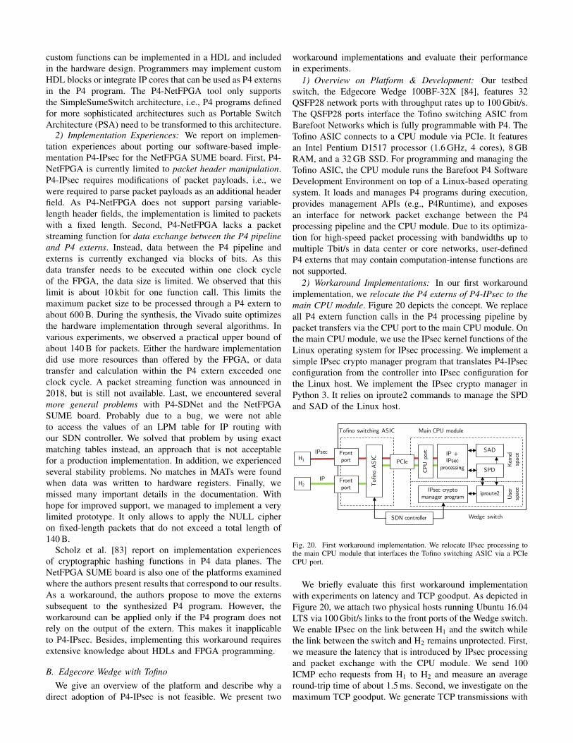
2) Workaround Implementations: In our first workaroundimplementation, we relocate the P4 externs of P4-IPsec to themain CPU module. Figure 20 depicts the concept. We replaceall P4 extern function calls in the P4 processing pipeline bypacket transfers via the CPU port to the main CPU module. Onthe main CPU module, we use the IPsec kernel functions of theLinux operating system for IPsec processing. We implement asimple IPsec crypto manager program that translates P4-IPsecconfiguration from the controller into IPsec configuration forthe Linux host. We implement the IPsec crypto manager inPython 3. It relies on iproute2 commands to manage the SPDand SAD of the Linux host.
Main CPU module
IPsec
Tofino switching ASIC
Front port
CPU
por
t
PCIe
Front port T
ofin
o A
SIC
IP
IP + IPsec
processing Ker
nel
spac
eU
ser
spac
e
iproute2IPsec crypto manager program
SDN controller
SAD
SPD
H1
H2
Wedge switch
Fig. 20. First workaround implementation. We relocate IPsec processing tothe main CPU module that interfaces the Tofino switching ASIC via a PCIeCPU port.
We briefly evaluate this first workaround implementationwith experiments on latency and TCP goodput. As depicted inFigure 20, we attach two physical hosts running Ubuntu 16.04LTS via 100 Gbit/s links to the front ports of the Wedge switch.We enable IPsec on the link between H1 and the switch whilethe link between the switch and H2 remains unprotected. First,we measure the latency that is introduced by IPsec processingand packet exchange with the CPU module. We send 100ICMP echo requests from H1 to H2 and measure an averageround-trip time of about 1.5 ms. Second, we investigate on themaximum TCP goodput. We generate TCP transmissions with
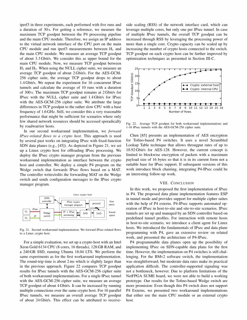
iperf3 in three experiments, each performed with five runs anda duration of 30 s. For getting a reference, we measure themaximum TCP goodput between the P4 processing pipelineand the main CPU module. Therefore, we assign an IP addressto the virtual network interface of the CPU port on the mainCPU module and run iperf3 measurements between H1 andthe main CPU module. We measure an average TCP goodputof about 3.3 Gbit/s. We consider this as upper bound for themain CPU module. Now, we measure TCP goodput betweenH1 and H2. When using the NULL cipher suite, we measure anaverage TCP goodput of about 2 Gbit/s. For the AES-GCM-256 cipher suite, the average TCP goodput drops to about1.4 Gbit/s. We repeat the experiment for 16 concurrent IPsectunnels and calculate the average of 10 runs with a durationof 300 s. The maximum TCP goodput remains at 2 Gbit/s forIPsec with the NULL cipher suite and 1.4 Gbit/s for IPsecwith the AES-GCM-256 cipher suite. We attribute the largedifferences in TCP goodput to the rather slow CPU with a basefrequency of 1.6 GHz. Still, we consider this a very reasonableperformance that might be sufficient for scenarios where onlyfew shared network resources should be accessed sporadicallyby roadwarrior hosts.
In our second workaround implementation, we forwardIPsec-related flows to a crypto host. This approach is usedby several past works on integrating IPsec with fixed-functionSDN data planes (e.g., [45]). As depicted in Figure 21, we setup a Linux crypto host for offloading IPsec processing. Wedeploy the IPsec crypto manager program from the previousworkaround implementation as interface between the cryptohost and controller. We deploy a simple P4 program on theWedge switch that forwards IPsec flows based on a MAT.The controller writes/edits the forwarding MAT on the Wedgeswitch and sends configuration messages to the IPsec cryptomanager program.
IPsec
IP
IPsec cryptomanager program
H1
H2
Linux crypto host
iproute2
SDN controller
Wedge switch
IP + IPsecprocessing SADSPD
User space
Kernel space
Fig. 21. Second workaround implementation. We forward IPsec-related flowsto a Linux crypto host.
For a simple evaluation, we set up a crypto host with an IntelXeon Gold 6134 CPU (8 cores, 16 threads), 128 GB RAM, anda 240 GB SSD, running Ubuntu 18.04 LTS. We perform thesame experiments as for the first workaround implementation.The round-trip time is about 2 ms which is slightly larger thanin the previous approach. Figure 22 compares TCP goodputresults for IPsec tunnels with the AES-GCM-256 cipher suiteof both workaround implementations. For a single IPsec tunnelwith the AES-GCM-256 cipher suite, we measure an averageTCP goodput of about 4 Gbit/s. It can be increased by runningmultiple connections over the same crypto host. For 16 parallelIPsec tunnels, we measure an overall average TCP goodputof about 24 Gbit/s. This effect can be attributed to receive-
side scaling (RSS) of the network interface card, which canleverage multiple cores, but only one per IPsec tunnel. In caseof multiple IPsec tunnels, the overall TCP goodput can beincreased through RSS by leveraging the processing power ofmore than a single core. Crypto capacity can be scaled up byincreasing the number of crypto hosts connected to the switch.TCP goodput on each crypto host can be further improved byoptimization techniques as presented in Section III-C.
1 2 3 4 5 6 7 8 9 10 11 12 13 14 15 16Number of flows
0
5
10
15
20
25
TC
P G
oodput
(Gbit
/s)
Crypto: external host
Crypto: internal CPU
Fig. 22. Average TCP goodput for both workaround implementations and1-16 IPsec tunnels with the AES-GCM-256 cipher suite.
Chen [85] presents an implementation of AES encryptionfor Tofino-based P4 switches. It uses a novel ScrambledLookup Table technique that allows througput rates of up to10.92 Gbit/s for AES-128. However, the current concept islimited to blockwise encryption of packets with a maximumpayload size of 16 bytes so that it is in its current form not asuitable base for IPsec support. If subsequent versions of thiswork introduce block chaining, integrating P4-IPsec could bean interesting follow-up work.
VIII. CONCLUSION
In this work, we proposed the first implementation of IPsecin P4. The proposed data plane implementation features ESPin tunnel mode and provides support for multiple cipher suiteswith the help of P4 externs. P4-IPsec supports automated op-eration of IPsec in host-to-site and site-to-site scenarios. IPsectunnels are set up and managed by an SDN controller based onpredefined tunnel profiles. For interaction with remote hostsin host-to-site scenario, we introduce a client agent for Linuxhosts. We introduced the fundamentals of IPsec and data planeprogramming with P4, gave an extensive review on relatedwork, and presented the architecture of P4-IPsec.
P4 programmable data planes open up the possibility ofimplementing IPsec on SDN-capable data plans for the firsttime. However, the implementation on P4 switches is still chal-lenging. For the BMv2 software switch, the implementationwas straightforward, but moderate data rates make its practicalapplication difficult. The controller-supported signaling wasnot a bottleneck, however. Due to platform limitations of theNetFPGA SUME board, we were not able to build a workingprototype. Our results for the Tofino-based Wedge switch aremore promision: Even though this P4 switch does not supportP4 Externs, we presented two workaround implementationsthat either use the main CPU module or an external cryptohost.
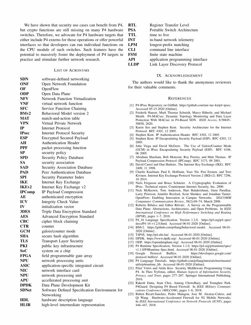
We have shown that security use cases can benefit from P4,but crypto functions are still missing on many P4 hardwareswitches. Therefore, we advocate for P4 hardware targets thateither include P4 externs for those operations or offer powerfulinterfaces so that developers can run individual functions onthe CPU module of such switches. Such features have thepotential to massively foster the deployment of P4 targets inpractice and stimulate further network research.
LIST OF ACRONYMS
SDN software-defined networkingONF Open Network FoundationOF OpenFlowODP Open Data PlaneNFV Network Function VirtualizationVNF virtual network functionSFC Service Function ChainingBMv2 Behavioral Model version 2MAT match-and-action tableVPN Virtual Private NetworkIP Internet ProtocolIPsec Internet Protocol SecurityESP Encrypted Secured PayloadAH Authentication HeaderPPF packet processing functionSP security policySPD Security Policy DatabaseSA security associationSAD Security Association DatabasePAD Peer Authentication DatabaseSPI Security Parameter IndexIKE Internet Key ExchangeIKEv2 Internet Key Exchange v2IPComp IP Payload CompressionAE authenticated encryptionICV Integrity Check ValueIV initialization vector3DES Triple Data Encryption StandardAES Advanced Encryption StandardCBC cipher block chainingCTR counterGCM galois/counter modeSHA secure hash algorithmTLS Transport Layer SecurityPKI public key infrastructureSoC system on a chipFPGA field programmable gate arrayNPU network processing unitsASIC application-specific integrated circuitNIC network interface cardNPU network processing unitAPU accellerated processing unitDPDK Data Plane Development KitSDNet Software Defined Specification Environment for
NetworkingHDL hardware description languageHLIR high-level intermediate representation
RTL Register Transfer LevelPSA Portable Switch ArchitectureTTL time to liveINT in-band network telemetryLPM longest-prefix matchingCLI command line interfaceFSM finite state machineAPI application programming interfaceLLDP Link Layer Discovery Protocol
IX. ACKNOWLEDGEMENT
The authors would like to thank the anonymous reviewersfor their valuable comments.
REFERENCES
[1] P4-IPsec Repository on GitHub. https://github.com/uni-tue-kn/p4-ipsec.Accessed 05-15-2020 [Online].
[2] Frederik Hauser, Mark Thomas Schmidt, Marco Häberle, and MichaelMenth. P4-MACsec: Dynamic Topology Monitoring and Data LayerProtection With MACsec in P4-Based SDN. IEEE Access, 8:58845–58858, 2020.
[3] Karen Seo and Stephen Kent. Security Architecture for the InternetProtocol. RFC 4301, 12 2005.
[4] Stephen Kent. IP Authentication Header. RFC 4302, 12 2005.[5] Stephen Kent. IP Encapsulating Security Payload (ESP). RFC 4303, 12
2005.[6] John Viega and David McGrew. The Use of Galois/Counter Mode
(GCM) in IPsec Encapsulating Security Payload (ESP). RFC 4106,06 2005.
[7] Abraham Shacham, Bob Monsour, Roy Pereira, and Matt Thomas. IPPayload Compression Protocol (IPComp). RFC 3173, 09 2001.
[8] David Carrel and Dan Harkins. The Internet Key Exchange (IKE). RFC2409, 11 1998.
[9] Charlie Kaufman, Paul E. Hoffman, Yoav Nir, Pasi Eronen, and TeroKivinen. Internet Key Exchange Protocol Version 2 (IKEv2). RFC 7296,10 2014.
[10] Niels Ferguson and Bruce Schneier. A Cryptographic Evaluation ofIPsec. Technical report, Counterpane Internet Security, Inc, 2000.
[11] Nick McKeown, Tom Anderson, Hari Balakrishnan, Guru Parulkar,Larry Peterson, Jennifer Rexford, Scott Shenker, and Jonathan Turner.OpenFlow: Enabling Innovation in Campus Networks. SIGCOMMCompututer Communication Review, 38(2):69–74, March 2008.
[12] Roberto Bifulco and Gábor Rétvári. A Survey on the ProgrammableData Plane: Abstractions, Architectures, and Open Problems. In IEEEInternational Conference on High Performance Switching and Routing(HPSR), pages 1–7, 2018.
[13] P4_16 Language Specification, Version 1.2.0. https://p4.org/p4-spec/docs/P4-16-v1.2.0.html. Accessed 06-01-2020 [Online].
[14] BMv2. https://github.com/p4lang/behavioral-model. Accessed 06-01-2020 [Online] .
[15] T4P4S. http://p4.elte.hu/. Accessed 06-01-2020 [Online].[16] DPDK. https://www.dpdk.org/. Accessed 06-01-2020 [Online].[17] ODP. https://opendataplane.org/. Accessed 06-01-2020 [Online].[18] P4 Runtime Specification, Version 1.1.0. https://p4.org/p4runtime/spec/
v1.1.0/P4Runtime-Spec.html. Accessed 06-01-2020 [Online].[19] Google Protocol Buffers. https://developers.google.com/
protocol-buffers/. Accessed 06-01-2020 [Online].[20] P4 Language Tutorials. https://github.com/p4lang/tutorials/tree/master/
utils/p4runtime_lib. Accessed 06-01-2020 [Online].[21] Péter Vörös and Attila Kiss. Security Middleware Programming Using
P4. In Theo Tryfonas, editor, Human Aspects of Information Security,Privacy, and Trust, pages 277–287. Springer International Publishing,2016.
[22] Rakesh Datta, Sean Choi, Anurag Chowdhary, and Younghee Park.P4Guard: Designing P4 Based Firewall. In IEEE Military Communi-cations Conference (MILCOM), pages 1–6, 2018.
[23] Ruben Ricart-Sanchez, Pedro Malagon, Jose M. Alcaraz-Calero, andQi Wang. Hardware-Accelerated Firewall for 5G Mobile Networks.In IEEE International Conference on Network Protocols (ICNP), pages446–447, 2018.
[24] Jiamin Cao, Jun Bi, Yu Zhou, and Cheng Zhang. CoFilter: A High-Performance Switch-Assisted Stateful Packet Filter. In ACM SIGCOMMConference (Posters and Demos), page 9–11, 2018.
[25] Eder Ollora Zaballa, David Franco, Zifan Zhou, and Michael S. Berger.P4Knocking: Offloading host-based firewall functionalities to the net-work. In Conference on Innovation in Clouds, Internet and Networksand Workshops (ICIN), pages 7–12, 2020.
[26] Amar Almaini, Ahmed Al-Dubai, Imed Romdhani, and MartinSchramm. Delegation of Authentication to the Data Plane in Software-Defined Networks. In IEEE International Conferences on UbiquitousComputing Communications (IUCC) and Data Science and Compu-tational Intelligence (DSCI) and Smart Computing, Networking andServices (SmartCNS), pages 58–65, 2019.
[27] Francesco Paolucci, Filippo Cugini, and Piero Castoldi. P4-based Multi-Layer Traffic Engineering Encompassing Cyber Security. In OpticalFiber Communications Conference and Exposition (OFC), pages 1–3,2018.
[28] Francesco Paolucci, Federico Civerchia, Andrea Sgambelluri, AlessioGiorgetti, Filippo Cugini, and Piero Castoldi. P4 Edge node enablingstateful traffic engineering and cyber security. IEEE/OSA Journal ofOptical Communications and Networking, 11(1):A84–A95, 2019.
[29] Marinos Dimolianis, Adam Pavlidis, and Vasilis Maglaris. A Multi-Feature DDoS Detection Schema on P4 Network Hardware. In Con-ference on Innovation in Clouds, Internet and Networks and Workshops(ICIN), pages 1–6, 2020.
[30] Aldo Febro, Hannan Xiao, and Joseph Spring. Telephony Denial ofService defense at data plane (TDoSD@DP). In IEEE/IFIP NetworkOperations and Management Symposium (NOMS), pages 1–6, 2018.
[31] Aldo Febro, Hannan Xiao, and Joseph Spring. Distributed SIP DDoSDefense with P4. In IEEE Wireless Communications and NetworkingConference (WCNC), pages 1–8, 2019.
[32] Garegin Grigoryan and Yaoqing Liu. LAMP: Prompt Layer 7 AttackMitigation with Programmable Data Planes. In ACM/IEEE Symposiumon Architectures for Networking and Communications Systems (ANCS),pages 1–4, 2018.
[33] Yehuda Afek, Anat Bremler-Barr, and Lior Shafir. Network Anti-Spoofing with SDN Data Plane. In IEEE Conference on ComputerCommunications (INFOCOM), pages 1–9, 2017.
[34] Ângelo Cardoso Lapolli, Jonatas Adilson Adilson Marques, and Lu-ciano Paschoal Gaspary. Offloading Real-time DDoS Attack Detectionto Programmable Data Planes. In IFIP/IEEE Symposium on IntegratedNetwork and Service Management (IM), pages 19–27, 2019.
[35] Mário Kuka, Kamil Vojanec, Jan Kucera, and Pavel Benácek. Accel-erated DDoS Attacks Mitigation using Programmable Data Plane. InACM/IEEE Symposium on Architectures for Networking and Communi-cations Systems (ANCS), pages 1–3, 2019.
[36] Yu Mi and An Wang. ML-Pushback: Machine Learning Based PushbackDefense Against DDoS. In International Conference on EmergingNetworking EXperiments and Technologies, page 80–81, 2019.
[37] Benjamin Lewis, Matthew Broadbent, and Nicholas Race. P4id: P4enhanced intrusion detection. In IEEE Conference on Network FunctionVirtualization and Software Defined Networks (NFV-SDN), pages 1–4,2019.
[38] Qiao Kang, Lei Xue, Adam Morrison, Yuxin Tang, Ang Chen, and XiapuLuo. Programmable In-Network Security for Context-aware BYODPolicies. In USENIX Security Symposium (USENIX Security). USENIXAssociation, 2020.
[39] Santiago Aragon, Marco Tiloca, Max Maass, Matthias Hollick, andShahid Raza. ACE of Spades in the IoT Security Game: A FlexibleIPsec Security Profile for Access Control. In IEEE Conference onCommunications and Network Security (CNS), 2018.
[40] Santiago Aragon, Marco Tiloca, and Shahid Raza. IPsec profile ofACE. Internet-Draft draft-aragon-ace-ipsec-profile-01, Internet Engi-neering Task Force, 10 2017. Work in Progress.
[41] David Carrel and Brian Weis. IPsec Key Exchange using a Controller.Internet-Draft draft-carrel-ipsecme-controller-ike-01, Internet Engineer-ing Task Force, 03 2019. Work in Progress.
[42] Xin Guo, Kun Yang, Alex Galis, Xiaochun Cheng, Bo Yang, and DayouLiu. A Policy-based Network Management System for IP VPN. InInternational Conference on Communication Technology (ICCT), pages1630–1633, 2003.
[43] Gabriel Lopez-Millan, Rafael Marin-Lopeza, and Fernando Pereniguez-Garcia. Towards a Standard SDN-based IPsec Management Framework.Elsevier Journal of Computer Standards & Interfaces, 66:103357, 2019.
[44] Jeongseok Son, Yongqiang Xiong, Kun Tan, Paul Wang, Ze Gan, andSue Moon. Protego: Cloud-Scale Multitenant IPsec Gateway. In USENIXAnnual Technical Conference (USENIX ATC), pages 473–485, 2017.
[45] Vajaranta, Markku and Kannisto, Joona and Harju, Jarmo. IPsec and IKEas Functions in SDN Controlled Network. In International Conferenceon Network and System Security (NSS), pages 521–530, 2017.
[46] Rafael Lopez, Gabriel Lopez-Millan, and Fernando Pereniguez-Garcia.Software-Defined Networking (SDN)-based IPsec Flow Protection.Internet-Draft draft-ietf-i2nsf-sdn-ipsec-flow-protection-07, Internet En-gineering Task Force, August 2019. Work in Progress.
[47] Anna Selvåg Braadland. Key Management for Data Plane Encryptionin SDN Using WireGuard. Master’s thesis, Norwegian Universityof Science and Technology, Department of Information Security andCommunication Technology, 2017.
[48] Ali Sajassi, Ayan Banerjee, Samir Thoria, David Carrel, Brian Weis,and John Drake. Secure EVPN. Internet-Draft draft-sajassi-bess-secure-evpn-02, Internet Engineering Task Force, July 2019. Work in Progress.
[49] Håkon Gunleifsen, Vasileios Gkioulos, and Thomas Kemmerich. ATiered Control Plane Model for Service Function Chaining Isolation.Future Internet Journal, 10:46, 2018.
[50] Håkon Gunleifsen, Thomas Kemmerich, and Vasileios Gkioulos. AProof-of-Concept Demonstration of Isolated and Encrypted ServiceFunction Chains. Future Internet, 11:183, 08 2019.
[51] Håkon Gunleifsen, Thomas Kemmerich, and Vasileios Gkioulos. Dy-namic setup of IPsec VPNs in Service Function Chaining. ElsevierJournal of Computer Networks, 160:77–91, 2019.
[52] Cisco: IPsec Management Configuration Guide. https://www.cisco.com/c/en/us/td/docs/ios-xml/ios/sec_conn_imgmt/configuration/xe-16/sec-ipsec-management-xe-16-book/sec-ipsec-snmp-supp.html.Accessed 01-06-2020 [Online].
[53] Adel Alharbi, Ayoub Bahnasse, Mohamed Talea, Hafsa Ait Oulahyane,and Fatima Ezzahraa Louhab. Smart SDN Policy Management BasedVPN Multipoint. Springer Lecture Notes in Real-Time IntelligentSystems, pages 250–263, 2019.
[54] Yunchun Li and Jutao Mao. SDN-based Access Authentication andAutomatic Configuration for IPsec. In International Conference onComputer Science and Network Technology (ICCSNT), pages 996–999,2015.
[55] Wei Li, Fengxu Lin, and Guanchao Sun. SDIG: Toward Software-Defined IPsec Gateway. In IEEE International Conference on NetworkProtocols (ICNP), pages 1–8, 2016.
[56] Marouen Mechtri, Ines Houidi, Wajdi Louati, and Djamal Zeghlache.SDN for Inter Cloud Networking. In IEEE SDN for Future Networksand Services (SDN4FNS), pages 1–7, 2013.
[57] Ronald van der Pol, Bart Gijsen, Piotr Zuraniewski, Daniel Filipe CabaçaRomão, and Marijke Kaat. Assessment of SDN Technology for an Easy-to-use VPN Service. Elsevier Journal of Future Generation ComputerSystems, 56:295–302, 2016.
[58] Luigi Rizzo. netmap: A Novel Framework for Fast Packet I/O. InUSENIX Annual Technical Conference (USENIX ATC), pages 101–112,2012.
[59] ntop: pf_ring. https://www.ntop.org/products/packet-capture/pf_ring/.Accessed 06-01-2020 [Online].
[60] Wei Li, Shengjie Hu, Guanchao Sun, and Yunchun Li. Adaptive LoadBalancing on Multi-core IPsec Gateway. In International Conference onAlgorithms and Architectures for Parallel Processing (ICA3PP), 2018.
[61] Gaogang Xie, Haiyang Jiang, and Kave Salamatian. Load Balancingby Ruleset Partition for Parallel IDS on Multi-Core Processors. InInternational Conference on Computer, Communication and Networks(ICCCN), 2013.
[62] Sangjin Han, Keon Jang, Kyoung Soo Park, and Sue B. Moon. Pack-etShader: A GPU-Accelerated Software Router. In ACM SIGCOMMConference, 2010.
[63] Sebastian Gallenmüller, Paul Emmerich, Florian Wohlfart, DanielRaumer, and Georg Carle. Comparison of Frameworks for High-Performance Packet IO. In ACM/IEEE Symposium on Architectures forNetworking and Communications Systems (ANCS), pages 29–38, 2015.
[64] Intel AES-NI. https://www.intel.de/content/www/de/de/architecture-and-technology/advanced-encryption-standard-aes/data-protection-aes-general-technology.html. Accessed 06-01-2020[Online].
[65] Architecture Reference Manual (ARMv8) for ARMv8-A ArchitectureProfile. Technical report, Arm Ltd., 2017.
[66] John DiGiglio and Davide Ricci. High Performance, Open Standard,Virtualization with NFV and SDN. Technical report, WindRiver, 2013.
[67] Algotronix AES IP-Cores. http://www.algotronix-store.com/AES_IP_Cores_s/20.htm. Accessed 06-01-2020 [Online].
[68] Chang-Soo Ha, Jong Hyoung Lee, Duck Soo Leem, Myoung-Soo Park,and Byeong-Yoon Choi. ASIC Design of IPsec Hardware Accelerator
for Network Security. In IEEE Asia-Pacific Conference on AdvancedSystem Integrated Circuits (APASIC), pages 168–171, 2004.
[69] Alireza Hodjat, Patrick Schaumont, and Ingrid Verbauwhede. Architec-tural Design Features of a Programmable High Throughput AES Copro-cessor. In IEEE International Conference on Information Technology:Coding and Computing (ITCC), 2004.
[70] Yizhen Liu, Daxiong Xu, Wuying Song, and Zhixin Mu. Design andImplementation of High Performance IPsec Applications with Multi-Core Processors. In IEEE International Seminar on Future InformationTechnology and Management Engineering (FITME), pages 595–598,2008.
[71] Jinli Meng, Xinming Chen, Zhen Chen, Chuang Lin, Beipeng Mu, andLingyun Ruan. Towards High-Performance IPsec on Cavium OCTEONPlatform. In International Conference on Trusted Systems (INTRUST),pages 37–46, 2011.
[72] Jungho Park, Wookeun Jung, Gangwon Jo, Ilkoo Lee, and Jaejin Lee.PIPSEA: A Practical IPsec Gateway on Embedded APUs. In ACMSIGSAC Conference on Computer and Communications Security (CCS),pages 1255–1267, 2016.
[73] Muzaffar Rao, Joseph Coleman, and Thomas Newe. An FPGA-basedReconfigurable IPsec ESP Core Suitable for IoT Applications. In IEEEInternational Conference on Sensing Technology (ICST), pages 1–5,2016.
[74] Markku Vajaranta, Vili Viitamäki, Arto Oinonen, Timo D. Hämäläinen,Ari Kulmala, and Jouni Markunmäki. Feasibility of FPGA AcceleratedIPsec on Cloud. In Euromicro Conference on Digital System Design(DSD), pages 569–572, 2018.
[75] Mateusz Korona, Krzysztof Skowron, Mateusz Trzepinski, and MariuszRawski. FPGA Implementation of IPsec Protocol Suite for MultigigabitNetworks. In IEEE International Conference on Systems, Signals andImage Processing (IWSSIP), pages 1–5, 2017.
[76] Benedikt Driessen, Tim Güneysu, Elif Bilge Kavun, Oliver Mischke,Christof Paar, and Thomas Pöppelmann. IPSecco: A lightweight andreconfigurable IPSec core. In International Conference on Reconfig-urable Computing and FPGAs (ReConFig), pages 1–7, 2012.
[77] [P4-dev] VPNs in P4. http://lists.p4.org/pipermail/p4-dev_lists.p4.org/2016-June/002109.html. Accessed 06-01-2020 [Online].
[78] Xilinx SDNet PX Programming Language User Guide.https://www.xilinx.com/support/documentation/sw_manuals/xilinx2017_3/ug1016-px-programming.pdf. Accessed 06-01-2020[Online].
[79] Vagrant. https://www.vagrantup.com/. Accessed 06-01-2020 [Online].[80] gRPC. https://grpc.io/. Accessed 06-01-2020 [Online].[81] netlink. http://man7.org/linux/man-pages/man7/netlink.7.html. Accessed
06-01-2020 [Online].[82] P4-NetFPGA Wiki. https://github.com/NetFPGA/P4-NetFPGA-public/.
Accessed 06-01-2020 [Online].[83] Dominik Scholz, Andreas Oeldemann, Fabien Geyer, Sebastian Gallen-
müller, Henning Stubbe, Thomas Wild, Andreas Herkersdorf, and GeorgCarle. Cryptographic Hashing in P4 Data Planes. In ACM/IEEE Sym-posium on Architectures for Networking and Communications Systems(ANCS), 2019.
[84] EdgeCore Wedge 100BF-32X. https://www.edge-core.com/productsInfo.php?cls=1&cls2=180&cls3=181&id=335. Accessed06-01-2020 [Online].
[85] Xiaoqi Chen. Implementing AES Encryption on Programmable Switchesvia Scrambled Lookup Tables. In ACM SIGCOMM Workshop on SecureProgrammable Network Infrastructure (SPIN), 2020.