Embed Size (px)
Citation preview
*P516-130*P516-130
AD-250Offline lock user guide
Instructions for programming AD-Series offline locks
Para el idioma español, navegue hacia www.schlage.com/support.Pour la portion française, veuillez consulter le site www.schlage.com/support.
2 • Schlage • AD-250 user guide
Contents
Overview ...........................................................................................................................3Getting started ..................................................................................................................4Schlage Utility Software (SUS) .........................................................................................4Construction access mode ...............................................................................................5
Create the master construction credential - locks with card readers ............................5Add Construction access mode user credentials - locks with card readers ..................5Cancel construction access mode ................................................................................5Locks with keypads .......................................................................................................5
Test lock operation ............................................................................................................6Mechanical test .............................................................................................................6Electronic test................................................................................................................6
Reset to factory defaults ...................................................................................................7Level 1 factory default reset ..........................................................................................7Level 2 factory default reset ..........................................................................................7
Batteries ...........................................................................................................................8To install or replace batteries ........................................................................................8Battery failure modes ....................................................................................................9
External power supply ......................................................................................................9LED reference .................................................................................................................10
Schlage Button ............................................................................................................10Inside Push Button (IPB) ............................................................................................10
Troubleshooting .............................................................................................................. 11FCC Statements .............................................................................................................12
This product is compliant of UL 294 and ULC S319 standard. This product’s compliance would be invalidated through the use of any add-on, expansion, memory or other module that has not yet been evaluated for compatibility for use with this UL Listed product, in accordance with the requirements of the Standards UL 294 and ULC S319. This product has been evaluated for CAN/ULC-S319 Class 1.
3
Overview
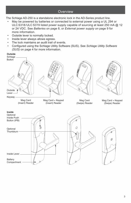
The Schlage AD-250 is a standalone electronic lock in the AD-Series product line. • May be powered by batteries or connected to external power using a UL 294 or
ULC S318/ULC S319 listed power supply capable of sourcing at least 250 mA @ 12 or 24 VDC. See Batteries on page 8, or External power supply on page 9 for more information.
• Outside lever is normally locked.• Inside lever always allows egress.• The lock maintains an audit trail of events.• Configured using the Schlage Utility Software (SUS). See Schlage Utility Software
(SUS) on page 4 for more information.OutsideSchlageButton
OutsideLever
Keyway
InsideOptionalInside PushButton (IPB)
OptionalThumbturn
Inside Lever
BatteryCompartment
Mag Card + Keypad (Insert) Reader
Mag Card (Insert) Reader
Mag Card + Keypad (Swipe) Reader
Mag Card (Swipe) Reader
AD-250-993AD-250-CYAD-250-MS
AD-250-MD
4 • Schlage • AD-250 user guide
Getting started
Follow these steps when setting up a new lock.1. Install the lock. See the installation guide that came with the lock, or visit
www.schlage.com/support, for more information.2. Make sure the batteries are installed properly. See Batteries on page 8 for more
information.3. Configure the master construction credential (where applicable). See Construction
access mode on page 5 for more information. The lock will remain in construction access mode until you are ready to set up the rest of the system.
4. Test the lock for proper mechanical and electronic operation. See Test lock operation on page 6 for more information.
5. Consult the Schlage Utility Software (SUS) user guide for information about configuring the lock.
6. Familiarize yourself with the information contained in this user guide.
Save this user guide for future reference.
Schlage Utility Software (SUS)
The Schlage Utility Software is used for programming and setup only.The Schlage Utility Software (SUS) is used to configure locks. This includes transferring data files between the access control software and locks. For further information about SUS, see the SUS user guide.
5
Construction access mode
Construction access mode is used to allow access before the lock has been programmed, and for testing purposes.• Enabled by default• The lock will remain in construction access mode
until the mode is cancelled as described below• No audits are captured while the lock is in
construction access mode.
Create the master construction credential - locks with card readersThe first card presented to a new lock automatically becomes the master construction credential.1. Press and hold the Schlage button while presenting a
credential.2. This credential becomes the master construction
credential, and is used to program construction access.
3. The Schlage button will blink on the left and right as confirmation.
After you have created the master construction credential, you can then use that card to add construction access mode user credentials.
L The Master construction credential will not grant access. It is used only to add additional credentials.
Add Construction access mode user credentials - locks with card readers1. Present the master construction credential to the lock. The Schlage button will light.2. Present the user credential to be added within twenty (20) seconds. The user credential
will be added to the lock database. L Credentials added using the master construction credential will have normal 24/7
access.
Cancel construction access modeDo one of the following:• Program the lock with the SUS. See the SUS user guide for more information.• Reset the lock to factory settings. See Reset to factory defaults on page 7 for more
information.
When construction mode is cancelled, the master construction credential and all other credentials added using the master construction credential will no longer function.
Locks with keypadsIn the factory default reset state, standalone locks with keypads, with or without additional credentials, have a default PIN of 13579 and “#”, which can be used for installation, testing and construction access. To test, enter default PIN. The Schlage button will blink and the lock will unlock.The default PIN is automatically deleted when a construction access user credential is added to the lock, or a new programming credential is created, or the lock is programmed with the SUS.
TIPSUse the same master construction credential for all the locks in the facility.If you present the first card to a new lock to create the master construction credential and the card is not accepted, the lock has either been programmed or already has a master construction credential.If the master construction credential cannot be located, or to put the lock back into construction access mode, reset the lock to factory settings. See Reset to factory defaults on page 7 for more information.
6 • Schlage • AD-250 user guide
Test lock operation
If you encounter problems while performing any of the following tests, review the installation guide and correct any problems.
Mechanical test1. Rotate the inside lever. Operation should be smooth, and the latch should retract.2. Insert the key into the keyway and rotate the key or the key and lever to open the door.
Operation should be smooth, and the latch should retract.
Electronic testTest the AD-250 in factory default mode1. For locks with a keypad, press any number key. The lock will beep.2. Press the Schlage button. The keypad should light blue for a few seconds.3. Present a credential to the reader. The lock will beep and the Schlage button will blink
red one time. When the lock is in factory default mode, no credentials are accepted. L If the lock does not acknowledge the credential presentation, be sure that there is
data on Track 2 of the credential. Default settings require data on Track 2.4. In the factory default state, locks with keypads, with or without additional credentials,
have a default PIN of 13579 and “#”. To test, enter default PIN. The Schlage button will blink and the lock will unlock.
Test the AD-250 in construction access mode1. When the master construction credential is presented, the lock will beep and the
Schlage button will light green for 20 seconds awaiting the presentation of another credential to be granted construction user access.
2. When a valid construction access user credential is presented, the lock will unlock for the re-latch delay period (default three seconds), and the Schlage button will blink green. When the lock re-locks after the re-latch delay period, the Schlage button will blink red.
3. If an invalid construction access user credential is presented, the lock will beep and the Schlage button will blink red twice. See Construction access mode on page 5 for more information.
L NOTE: Construction access mode is cancelled when the lock is reset to factory defaults. When construction access mode is cancelled, the master construction credential and all other credentials added using the master construction credential will no longer function.
7
Reset to factory defaults
All information in the lock will be deleted and reset to factory defaults!
Level 1 factory default reset L Level 1 factory default reset will delete configurations and settings in the main
controller in the lock. L Main controller configurations that will reset to factory default include:
programming and user codes. L Level 1 factory default reset will not reset configurations and settings in the
reader.1. Remove the top inside cover.2. Press and hold the Schlage button until two (2) beeps sound (10 seconds).3. Release the Schlage button.4. Press and release the inside push button (IPB) three (3) times within 10 seconds. One
beep will sound and one red blink will occur with each press.5. The Schlage button and IPB will both light green for one second and a one-second beep
will be heard. This indicates that the lock has been reset. L If the IPB is not pressed 3 times within 10 seconds, two beeps with two red blinks
indicate timeout.6. Replace the top inside cover.
Level 2 factory default reset L Level 2 factory default reset will delete all configurations and settings in the lock
and the reader. L Reader configurations that will reset to factory default include: keypad format,
magstripe reader track, beeper on/off, and contactless card. L Days in Use counter and lock type configurations will not reset.
To complete Level 2 factory default reset, repeat steps 2 through 5 above within 10 seconds of the confirmation signals of Level 1 factory default reset. If more than 10 seconds pass after the confirmation signals of Level 1 reset, then Level 1 reset will be repeated.
8 • Schlage • AD-250 user guide
Batteries
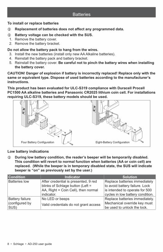
To install or replace batteries L Replacement of batteries does not affect any programmed data. L Battery voltage can be checked with the SUS.
1. Remove the battery cover.2. Remove the battery bracket.
Do not allow the battery pack to hang from the wires.3. Install the new batteries (install only new AA Alkaline batteries).4. Reinstall the battery pack and battery bracket.5. Reinstall the battery cover. Be careful not to pinch the battery wires when installing
the battery cover.CAUTION! Danger of explosion if battery is incorrectly replaced! Replace only with the same or equivalent type. Dispose of used batteries according to the manufacturer’s instructions.This product has been evaluated for ULC-S319 compliance with Duracell Procell PC1500 AA alkaline batteries and Panasonic CR2025 lithium coin cell. For installations requiring ULC-S319, these battery models should be used.
Four Battery Configuration Eight-Battery Configuration
Low battery indications L During low battery condition, the reader’s beeper will be temporarily disabled.
This condition will revert to normal function when batteries (AA or coin cell) are replaced. (While the beeper is in temporary disabled state, the SUS will indicate beeper is “on” as previously set by the user.)
Condition Indicator SolutionBatteries low After credential is presented, 9 red
blinks of Schlage button (Left = AA, Right = Coin Cell), then normal indicator.
Replace batteries immediately to avoid battery failure. Lock is intended to operate for 500 cycles in low battery condition.
Battery failure (configured by SUS)
No LED or beepsValid credentials do not grant access
Replace batteries immediately. Mechanical override key must be used to unlock the lock.
9
Battery failure modes L The battery failure mode is set using the SUS. See the SUS user guide for more
information.
Mode DescriptionFail As-Is (default) Lock remains in current state until batteries are replaced.Fail Unlocked1 Lock unlocks and remains unlocked until batteries are replaced.Fail Locked1 Lock locks and remains locked until batteries are replaced.
1 Fail Unlocked and Fail Locked modes are not available if lock is externally powered.
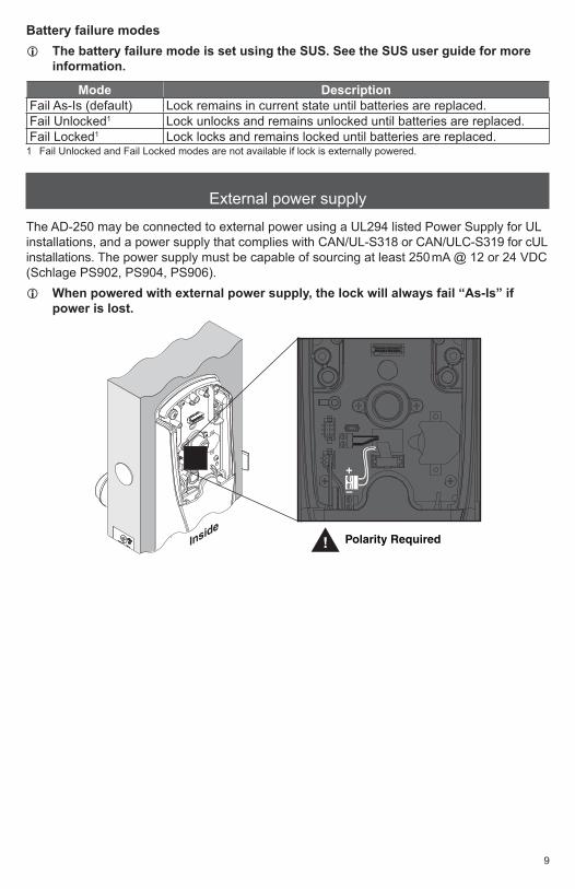
External power supply
The AD-250 may be connected to external power using a UL294 listed Power Supply for UL installations, and a power supply that complies with CAN/UL-S318 or CAN/ULC-S319 for cUL installations. The power supply must be capable of sourcing at least 250mA @ 12 or 24 VDC (Schlage PS902, PS904, PS906).
L When powered with external power supply, the lock will always fail “As-Is” if power is lost.
–
+
Inside! Polarity Required
10 • Schlage • AD-250 user guide
LED reference
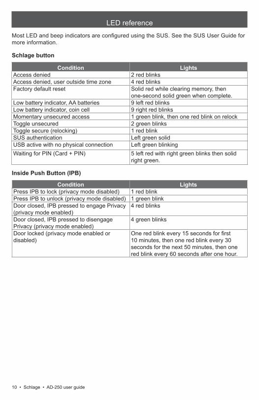
Most LED and beep indicators are configured using the SUS. See the SUS User Guide for more information.
Schlage button
Condition LightsAccess denied 2 red blinksAccess denied, user outside time zone 4 red blinksFactory default reset Solid red while clearing memory, then
one-second solid green when complete.Low battery indicator, AA batteries 9 left red blinksLow battery indicator, coin cell 9 right red blinksMomentary unsecured access 1 green blink, then one red blink on relockToggle unsecured 2 green blinksToggle secure (relocking) 1 red blinkSUS authentication Left green solidUSB active with no physical connection Left green blinkingWaiting for PIN (Card + PIN) 5 left red with right green blinks then solid
right green.
Inside Push Button (IPB)
Condition LightsPress IPB to lock (privacy mode disabled) 1 red blinkPress IPB to unlock (privacy mode disabled) 1 green blinkDoor closed, IPB pressed to engage Privacy (privacy mode enabled)
4 red blinks
Door closed, IPB pressed to disengage Privacy (privacy mode enabled)
4 green blinks
Door locked (privacy mode enabled or disabled)
One red blink every 15 seconds for first 10 minutes, then one red blink every 30 seconds for the next 50 minutes, then one red blink every 60 seconds after one hour.
11
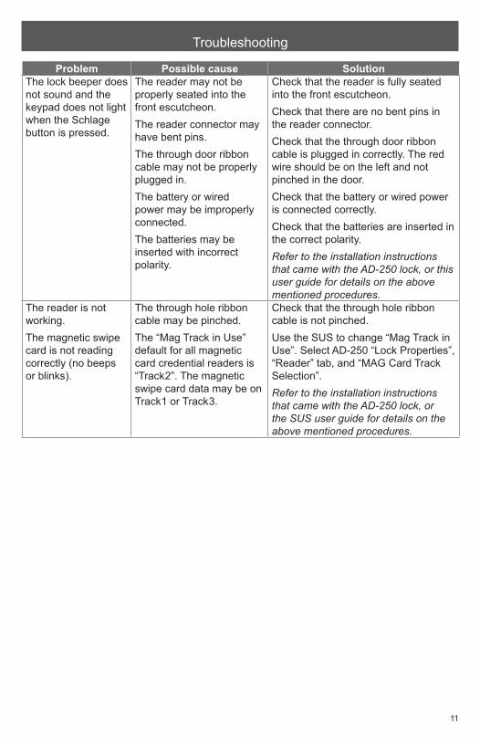
Troubleshooting
Problem Possible cause SolutionThe lock beeper does not sound and the keypad does not light when the Schlage button is pressed.
The reader may not be properly seated into the front escutcheon.The reader connector may have bent pins.The through door ribbon cable may not be properly plugged in.The battery or wired power may be improperly connected.The batteries may be inserted with incorrect polarity.
Check that the reader is fully seated into the front escutcheon.Check that there are no bent pins in the reader connector.Check that the through door ribbon cable is plugged in correctly. The red wire should be on the left and not pinched in the door.Check that the battery or wired power is connected correctly.Check that the batteries are inserted in the correct polarity.Refer to the installation instructions that came with the AD-250 lock, or this user guide for details on the above mentioned procedures.
The reader is not working.The magnetic swipe card is not reading correctly (no beeps or blinks).
The through hole ribbon cable may be pinched.The “Mag Track in Use” default for all magnetic card credential readers is “Track2”. The magnetic swipe card data may be on Track1 or Track3.
Check that the through hole ribbon cable is not pinched.Use the SUS to change “Mag Track in Use”. Select AD-250 “Lock Properties”, “Reader” tab, and “MAG Card Track Selection”.Refer to the installation instructions that came with the AD-250 lock, or the SUS user guide for details on the above mentioned procedures.
Customer Service1-877-671-7011 www.allegion.com/us
© Allegion 2014Printed in U.S.A.
P516-130 Rev. 03/14-h
FCC Statements
Allegion Agency StatementsCompliance Statement (Part 15.19)This device complies with Part 15 of the FCC Rules.Operation is subject to the following two conditions:
1. This device may not cause harmful interference, and2. This device must accept any interference received, including interference that may cause undesired operation.