Embed Size (px)
Citation preview
2004/10/29 < 1>© MAN B&W Diesel
Pacific Ports Air Quality Collaborative Conference Dec. 2006.
How engine manufacturers are meeting the challenge by refining their technologies within Exhaust gas emission
Kjeld Aabo
Director Customer Support

< 2>
MAN B&W Diesel
© MAN B&W Diesel
6S35MC and 10K98MC-C on Test bed
L/70479-5.0/0100 (2700/JGJ)
< 3>
MAN B&W Diesel
© MAN B&W Diesel
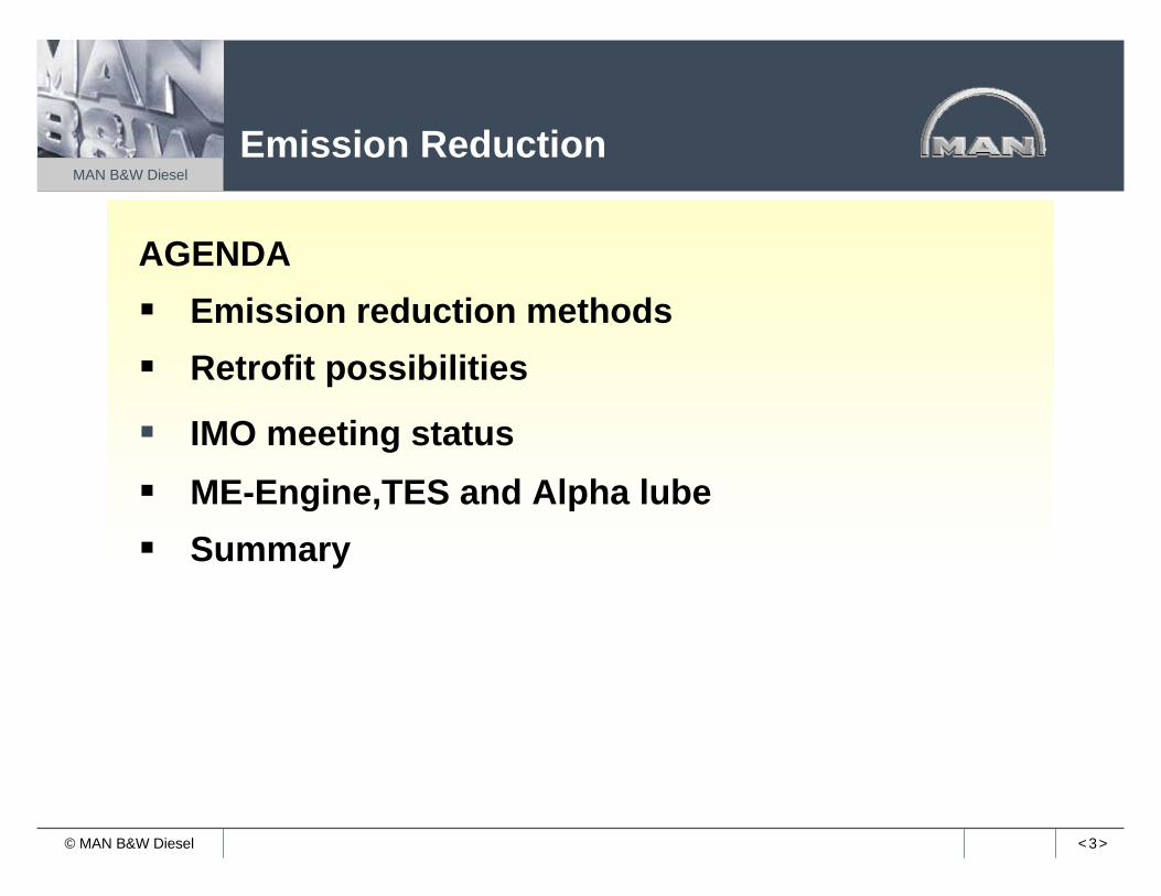
Emission Reduction
AGENDAEmission reduction methodsRetrofit possibilities
IMO meeting statusME-Engine,TES and Alpha lubeSummary

< 4>
MAN B&W Diesel
© MAN B&W Diesel
Emission ReductionMethods
Internal measures:Performance and Spray Optimization
Flexibility of Electronic EnginesWater-in-Fuel Emulsion or Direct Injection (FWE, FWI)Saturated Air Moisturising (SAM or HAM)Exhaust Gas Recirculation (EGR)
Aftertreatment:Selectiv Catalytic Reduction (SCR)Particulate Filters (ESP)Scrubbers (wet or dry FGS)

< 5>
MAN B&W Diesel
© MAN B&W Diesel
Heat
Work
Air8.5 kg/kWh
21% O279% N2
Fuel175 g/kWh97% HC
3% S
Lube1 g/kWh97% HC
2.5% CA0.5% S
Exhaust gas13.0% O275.8% N25.2% CO2
5.35% H2O
1500 vppm NOx600 vppm SOx
60 ppm CO180 ppm HC120 mg/Nm3 part.
3331588/20040525 (2160/KEA)

< 6>
MAN B&W Diesel
© MAN B&W Diesel 3331589/20040525 (2160/KEA)
Up to 98% reductionNOx
2) Use of water emulsion
From 20-50%NOx reduction
To comply with Tier 1 EPA and IMO NO code
1) Modification of injection equipment
receiver
3) Use of selective catalytic reduction
SCR reactor
Exhaust gas
x

< 7>
MAN B&W Diesel
© MAN B&W Diesel
Cross sections of fuel-valve nozzle tips
Valve Designs
< 8>
MAN B&W Diesel
© MAN B&W Diesel
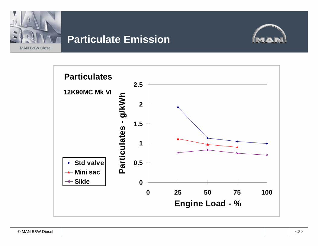
0
0.5
1
1.5
2
2.5
0 25 50 75 100
Engine Load - %
Part
icul
ates
- g/
kWh
Std valveMini sacSlide
Particulates
12K90MC Mk VI
Particulate Emission

< 9>
MAN B&W Diesel
© MAN B&W Diesel
0
0.5
1
1.5
2
2.5
3
3.5
0 25 50 75 100
Engine Load - %
HC
(as
CH
4) -
g/kW
h
Std valveMini sacSlide
Hydrocarbons
12K90MC Mk VI
Hydrocarbon Emission

< 10>
MAN B&W Diesel
© MAN B&W Diesel
NOx Emission ControlWater Emulsion Fuel
From centrifuge
Aut. deaerating valve
Venting box
Fresh water supply
Supplypumps
Circulatingpumps
Fullflowfilter
Fuel oildrain tank
Heavyfueloil
servicetank
Dieseloil
servicetank
Homo-genizer
Preheater
< 11>
MAN B&W Diesel
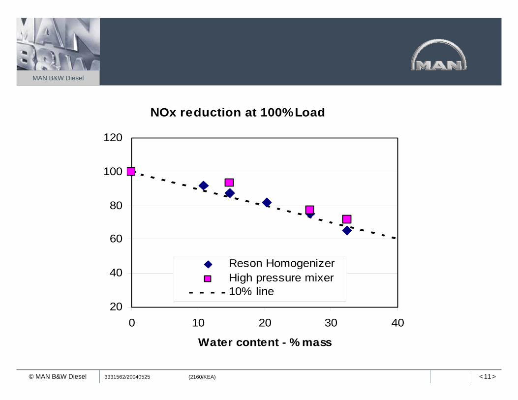
© MAN B&W Diesel 3331562/20040525 (2160/KEA)
NOx reduction at 100% Load
20
40
60
80
100
120
0 10 20 30 40
Water content - % mass
Reson HomogenizerHigh pressure mixer10% line

< 12>
MAN B&W Diesel
© MAN B&W Diesel
Alternative SCR configurations
Traditional vertical SCR
Engine integrated SCR
Horizontal SCR
Partial SCR
MAN B&W Diesel patent MAN B&W Diesel patent

< 13>
MAN B&W Diesel
© MAN B&W Diesel
SCR System
L/71835-9.0/0801 (2160/PZS)
32
1
5
6
78
4
Deck
1 SCR reactor
2 Turbocharger bypass
3 Temperature sensor after SCR
4 Large motors forauxiliary blowers
5 Urea injector
6 SCR bypass
7 Temperature sensorbefore SCR
8 Additional flange in exhaustgas receiver
6S35MC

< 14>
MAN B&W Diesel
© MAN B&W Diesel
40 MW KOMIPO Plant at Cheju, Korea 12K80MC-S
3332030/20041123 (3230/JH)
SCR Installation
12700
2425
0
< 15>
MAN B&W Diesel
© MAN B&W Diesel
3332029/20041123 (3230/JH)
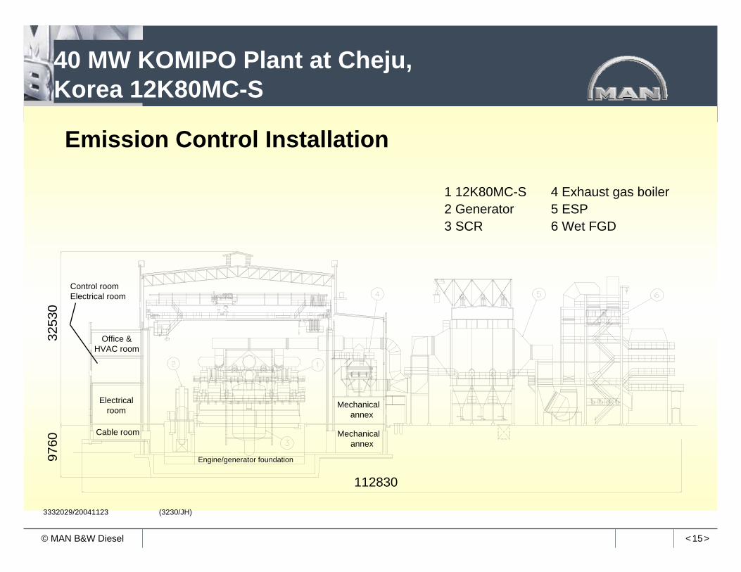
40 MW KOMIPO Plant at Cheju, Korea 12K80MC-S
Emission Control Installation
3253
0
112830
Mechanicalannex
9760
Mechanicalannex
Office &HVAC room
Control roomElectrical room
Electricalroom
Engine/generator foundation
Cable room
4 Exhaust gas boiler5 ESP6 Wet FGD
1 12K80MC-S2 Generator3 SCR

< 16>
MAN B&W Diesel
© MAN B&W Diesel
Total Emission Control System 40 MW Power Plant, Buk Cheju, Korea
3334437.2006.09.18 (3230/JH)
MAN B&W two-stroke diesel engine 12K80MC-SEmission limits:
SOx < 50 ppm at 4% O2, dry gas
NOx < 250 ppm at 13% O2, dry gas
PM < 30 mg/Sm3 at 4% O2, dry gas

< 17>
MAN B&W Diesel
© MAN B&W Diesel
APM – CARB (et. al.) demo on SL valves and reduced speed (finished)
APL – CARB (et. al.) demo on SL valves, reduced speed and water emulsion (in progress)
Wallenius, investigation on SAM system (in progress)
Acknowledgements –Demo on Existing Engines
< 18>
MAN B&W Diesel
© MAN B&W Diesel
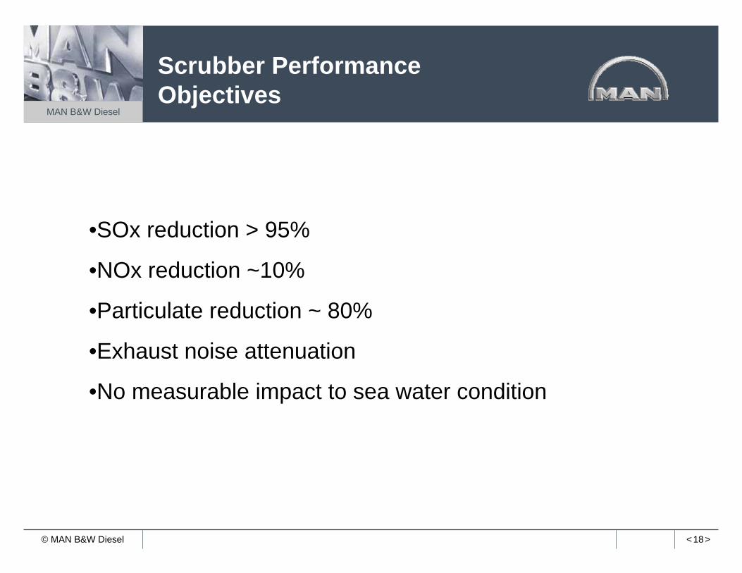
Scrubber Performance Objectives
•SOx reduction > 95%
•NOx reduction ~10%
•Particulate reduction ~ 80%
•Exhaust noise attenuation
•No measurable impact to sea water condition

< 19>
MAN B&W Diesel
© MAN B&W Diesel
Stationary Applications
DeSOx/de-dust testfacility at Ibiza, Spain
3330617.2003.09.07 (3230/JH)

< 20>
MAN B&W Diesel
© MAN B&W Diesel
mv Pride of Kent project
First commercial scrubber installation

< 21>
MAN B&W Diesel
© MAN B&W Diesel
EGRunit
Schematic Design of EGR system
L/73395-9.0/0902 (2430/NK)
Low O2 in scavenge air gives low combustion temperatures
Re-circulation of exhaust gas lowers O2 in scavenge air
Low combustion temperatures give low NOx
EGR influence on NOx formation
Influence on reliability and safety: Field test

< 22>
MAN B&W Diesel
© MAN B&W Diesel
Temperature Distribution
L/74189-3.0/0402 (2430/NK)
Without EGR With 15% EGR
4T50ME-X combustion chamberTemperature distribution in a horizontal incision in line with the atomizer holes
240023802360234023202300228022602240222022002180216021402120210020802060204020202000
Temperatureabsolute kelvin
< 23>
MAN B&W Diesel
© MAN B&W Diesel
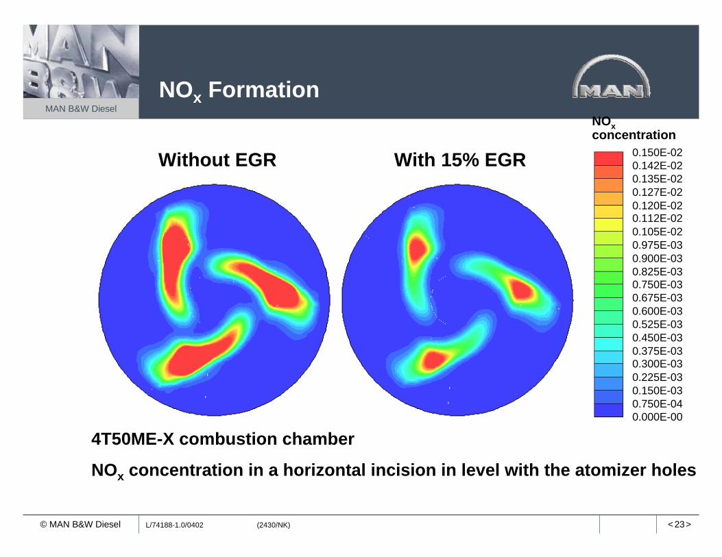
NOx Formation
L/74188-1.0/0402 (2430/NK)
Without EGR With 15% EGR
4T50ME-X combustion chamber
NOx concentration in a horizontal incision in level with the atomizer holes
0.150E-020.142E-020.135E-020.127E-020.120E-020.112E-020.105E-020.975E-030.900E-030.825E-030.750E-030.675E-030.600E-030.525E-030.450E-030.375E-030.300E-030.225E-030.150E-030.750E-040.000E-00
NOxconcentration

< 24>
MAN B&W Diesel
© MAN B&W Diesel
NOx Emission ControlEGR Emission Parameters
100
100
90
80
100
90
200
100
80
60
150
EGR ratio %
Relative change %
0 105 15 20
NOx
CO
HC
PM
40
100
100
90
80
100
90
200
100
80
60
150
EGR ratio %
Relative change %
0 105 15 20
NOx
CO
HC
PM
40
Emission Parameters at 75% Load at VariousEGR Ratios
< 25>
MAN B&W Diesel
© MAN B&W Diesel
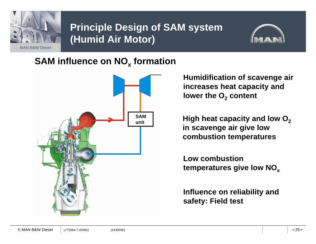
Principle Design of SAM system (Humid Air Motor)
L/73394-7.0/0902 (2430/NK)
SAMunit High heat capacity and low O2
in scavenge air give low combustion temperatures
Humidification of scavenge air increases heat capacity and lower the O2 content
Low combustion temperatures give low NOx
SAM influence on NOx formation
Influence on reliability and safety: Field test

< 26>
MAN B&W Diesel
© MAN B&W Diesel
NOx Emission ControlSAM Emission Parameters
Absolute humidity (vol./vol.) of scavenge air (%)
110 100
100
90
300 200 100
%
100 80
60
PM
HC
CO
NOx
zero half full0 3 6 9

< 27>
MAN B&W Diesel
© MAN B&W Diesel
NOx Emission Control, SAM Application and Conventional Cooler

< 28>
MAN B&W Diesel
© MAN B&W Diesel
SAM Service application
L/74217-0.0/0502 (2430/NK)
< 29>
MAN B&W Diesel
© MAN B&W Diesel
L/73847-8.0/0303 (2440/PCS)
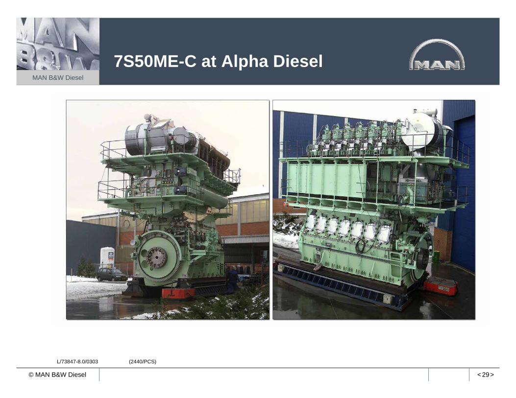
7S50ME-C at Alpha Diesel

< 30>
MAN B&W Diesel
© MAN B&W Diesel L/74496-0.1/0903 (2430/NK)
0
100
200
300
400
500
600
700
800
900
1000
1100
1200
1300
16:37 16:38 16:39 16:40 16:41 16:42 16:43 16:44 16:45 16:46
NO
x[p
pm]
2003-02-17
140 150 160 170 180 190 200 210 220 2300 0
20 100
40 200
60 300
80 400
100 500
120 600
140 700
160 800
CylinderPump
2003-02-17
140 150 160 170 180 190 200 210 220 2300 0
20 100
40 200
60 300
80 400
100 500
120 600
140 700
160 800
CylinderPump
Economy mode Low NOX mode
Time
NOx and economy mode ME engine
< 31>
MAN B&W Diesel
© MAN B&W Diesel
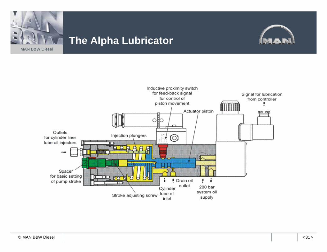
The Alpha Lubricator

< 32>
MAN B&W Diesel
© MAN B&W Diesel
Lube oil related HC-Emission
Lub. Oil HC-Emission
0
20
40
60
80
100
0 25 50 75 100Load (%MCR)
Reference
Alpha Lubricator
HC
ppm
< 33>
MAN B&W Diesel
© MAN B&W Diesel
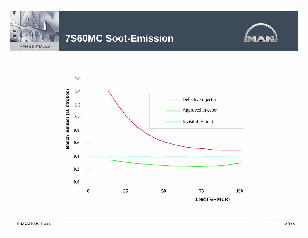
7S60MC Soot-Emission
0.0
0.2
0.4
0.6
0.8
1.0
1.2
1.4
1.6
0 25 50 75 100
Load (% - MCR)
Defective injector
Approved injector
Invisibility limit
Bos
chnu
mbe
r(10
str
okes
)

< 34>
MAN B&W Diesel
© MAN B&W Diesel
Green Shipping World, Amsterdam17 & 18 May 2005
0
0.5
1
1.5
2
2.5
3
3.5
0 25 50 75 100
Engine Load - %
HC
(as
CH
4) -
g/kW
h
Std valveMini sacSlide
Hydrocarbons
12K90MC Mk VI

< 35>
MAN B&W Diesel
© MAN B&W Diesel
Low Sulphur Fuel Operation
Two-stroke engine can operate on HFO, GO, DO
Two-stroke engine is less sensitive to fuel quality
Cylinder lube oil base numbers are to be considered
When fuel is mixed to reduce sulphur control fuels, compatibility becomes important
More fuel and cylinder lube oil storage tankers to be implemented on new-buildings
Conclusion: When operating on low sulphur fuels different considerations are to be made

< 36>
MAN B&W Diesel
© MAN B&W Diesel
Pump StationPower concept for a Thermo Efficiency System
Exhaust Gas Heat Recovery(single pressure)
Superheated steam
TG
Generator PTSwitchboard
Diesel generators
Exhaust gas receiver
Main engine
Shaft/motorgenerator
EmergencygeneratorTG: Turbogenerator
PT: Power turbineTC: TurbochargerSaturated
steam for heatingpurposes
Exh. Gas boiler
TC
< 37>
MAN B&W Diesel
© MAN B&W Diesel 3332167.2005.02.04 (2160/BGJ)
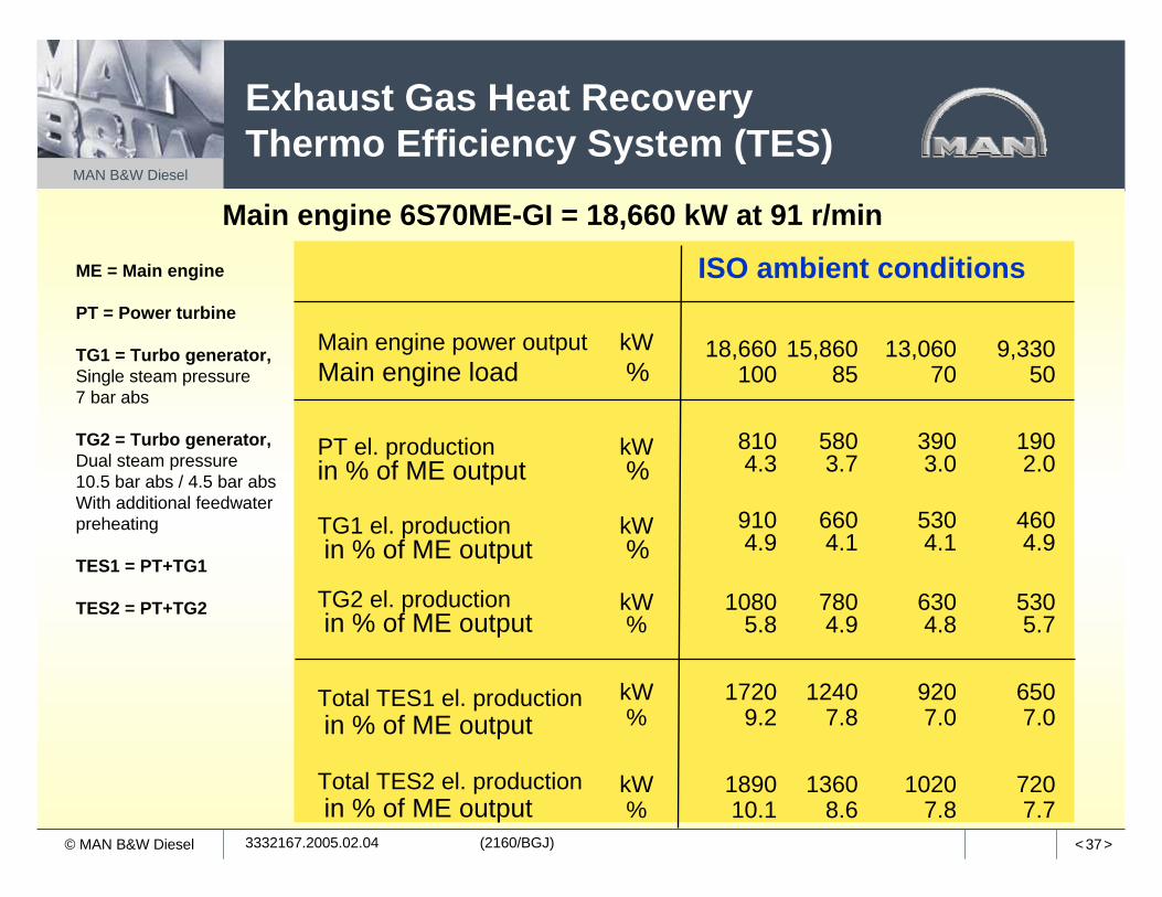
Main engine 6S70ME-GI = 18,660 kW at 91 r/min
ME = Main engine
PT = Power turbine
TG1 = Turbo generator, Single steam pressure7 bar abs
TG2 = Turbo generator, Dual steam pressure10.5 bar abs / 4.5 bar absWith additional feedwaterpreheating
TES1 = PT+TG1
TES2 = PT+TG2
Exhaust Gas Heat RecoveryThermo Efficiency System (TES)
7207.7
10207.8
13608.6
189010.1
kW%
Total TES2 el. productionin % of ME output
6507.0
9207.0
12407.8
17209.2
kW%
Total TES1 el. productionin % of ME output
5305.7
6304.8
7804.9
10805.8
kW%
TG2 el. productionin % of ME output
4604.9
5304.1
6604.1
9104.9
kW%
TG1 el. productionin % of ME output
1902.0
3903.0
5803.7
8104.3
kW%
PT el. productionin % of ME output
9,33050
13,06070
15,86085
18,660100
kW%
Main engine power outputMain engine load
ISO ambient conditions

< 38>
MAN B&W Diesel
© MAN B&W Diesel
TES Engine Test
TES Engine TestsNOx Emission
80
90
100
110
120
130
60.00 70.00 80.00 90.00 100.00 110.00
Engine load in %
Rela
tive
NOx
emis
sion
in %
ReferenceScav-BypassSc-by+Sc-Ex-by
< 39>
MAN B&W Diesel
© MAN B&W Diesel
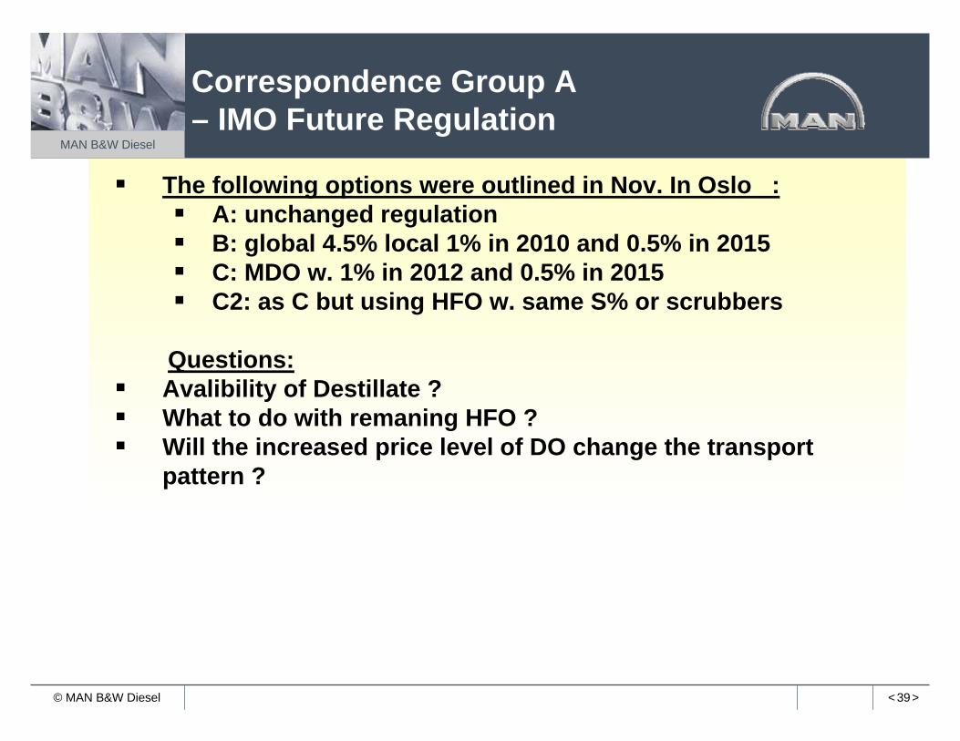
Correspondence Group A– IMO Future Regulation
The following options were outlined in Nov. In Oslo :A: unchanged regulationB: global 4.5% local 1% in 2010 and 0.5% in 2015C: MDO w. 1% in 2012 and 0.5% in 2015C2: as C but using HFO w. same S% or scrubbers
Questions:Avalibility of Destillate ?What to do with remaning HFO ?Will the increased price level of DO change the transport pattern ?

< 40>
MAN B&W Diesel
© MAN B&W Diesel
Summary – orHow to Comply with the IMO C3 Regulation
• Speed reduction strongly affectsemissions
• Slide valves and Alpha lube promoted as retrofits for ‘old’engines
• Voluntary compliance with Tier 3 & Tier 4 may be possible in limited scale
• Coastal NO control area (NECA)• SCR voluntary (incentives)
Comments
• SAM (EGR, SCR)• CO2 & sfoc penalty 5+%
• 50%? NOx reduction (from Tier 1)
Tier 4
• Fuel-water emulsion• CO2 & sfoc penalty 3+%
• 30% NOx reduction (from Tier 1)From Jan. 2015
Tier 3
• Fuel nozzle & performance optimization
• Slide valves mandatory• (a few MC engine types may need
H2O addition)• CO2 & sfoc penalty 1-3%
• 10-15% NOx reduction (from Tier 1)
• HC and CO must not increase• PM & SOx by fuel Sulfur contentFrom Jan. 2010
Tier 2
• Fuel nozzle & performance optimization
• 5% sfoc tolerance
Current IMO Regulation• NOx speed limit curve• SOx – fuel Sulfur content limitFrom 1 Jan. 2000 to end Dec. 2009
Tier 1Reduction methodRegulationIMO

< 41>
MAN B&W Diesel
© MAN B&W Diesel
Slide-type fuel valves (tier 2)Alpha lubricator system (tier 2)Water-in-fuel emulsion (tier 2 or 3)SAM & EGR systems (tier 3 or 4)Scrubber systems (alternative)SCR (special areas)
(in order of increasing difficulty & cost)
Retrofit Possibilities

< 42>
MAN B&W Diesel
© MAN B&W Diesel
Strong impact from fuel nozzles on NOx, soot and smoke. (SL valves easy to retrofit)
Alpha lube-oil system saves lube oil and improves cylinder conditions. (Easy to retrofit)
The ME engine improves emission optimisation and allows different optimisation for local areas
Water emulsification possible for future NOx requirements – if required. (Possible to retrofit, but need decision on scope)
SAM (and EGR) have potentials, but further tests are needed
Summary –reduction methods

< 43>
MAN B&W Diesel
© MAN B&W Diesel
NOx Reduction Potential
5
10
15
17
Uncontrolled = Fuel optimized
IMO compliant = Fuel system adoption(additional low NOx optimization)
Lower future IMO/ EPA = ME optimization= Water in combustion (WFE,WFI)
Local regulation = EGR (under development)= SAM (under development)= Combinations of WFE, SAM & EGR
Lowest = SCR (NH3 or UREA)
NOxg/kWh