Embed Size (px)
Citation preview
Abstract— Carbon nanotube (CNT) based devices have shown a higher order of magnitude in terms of both energy and power densities. Super capacitors also find attractive applications in consumer electronic products and alternative power source due to its higher energy density, fast discharge/charge time, low level of heating, safety, long-term operation stability, and no disposable parts. This paper gives a comprehensive understanding of the advantages and disadvantages of carbon nanotubes-related super capacitor materials and to find ways for the improvement in the performance of super capacitor. The purpose of this research is to find a technique that produces functional carbon nanotube based electrodes for super capacitor assembly. The electrochemically co-deposited composites are the most homogeneous and show an unusual interaction between the polymer and carbon nanotubes, giving rise to a strengthened electron delocalization and conjugation along the polymer chains. As a result they exhibit excellent electrochemical charge storage properties and fast charge/discharge switching, making them promising electrode materials for high power super capacitors. Keywords—Alternative power source, Fast charge/discharge, Carbon Nanotube, Super capacitor.
I. INTRODUCTION RINTING is the reproduction of one or more images on a variety of substrates that can be seen or perceived visually [1]. In the past, printing was a means of
graphically communicating ideas in publication and packaging applications. Now, printing has transformed into its own science with the printing of circuits, lighting, and even energy storage devices[2]. Currently available on the market are supercapacitors made from activated charcoal that have less energy storage, but more power than batteries[3]. Carbon nanotubes (sheets of graphene rolled into tubules), are an alternative to activated charcoal that offer the opportunity to increase the power as well as the energy storage capabilities of supercapacitors[4].Printing affords the opportunity to print large quantities of supercapacitors at a lower applied cost (when using carbon nanotubes) in comparison with other methodologies Manuscript received April 03, 2015; revised April 16, 2015. Pooja Pragati is a student with the SRM University, Chennai-603 203 (Phone: +91-7639125999; e-mail: [email protected]). Sudarsan Baskar is a student with the SRM University, Chennai-603 203 (Phone: +91-8754561964; e-mail: [email protected]). Karthika chandrababu is an assistant professor with the SRM University, Chennai-603203 (e-mail: [email protected]).
currently being employed (spin coating, pill pressing, etc.) Thus, printing carbon nanotubes is a desirable means to manufacture supercapacitors. The challenge of printing supercapacitors is not limited simply to the print, but also to the packaging and how that will affect the performance of the supercapacitor. Important issues that need to be considered when producing carbon nanotube based supercapacitors include the substrate to be printed on, the membrane separator layer to be used to separate two electrodes from one another and allow ion transfer, and the adhesive to be used to seal the substrate to be air tight around the printed electrode [5]. The concepts focused on for this research include substrate selection, membrane selection, and ink creation for the electrode. It takes all of these components to create a complete packaged and functioning supercapacitor. This research’s focus is that the supercapacitor can be printed on a consumer goods package to provide power for packaging features such as intelligent packaging. One such application that could be envisioned is a food package, which tracks the atmosphere in the package and reduces the package price for “quick sale” as the atmosphere indicates that the shelf life is nearing its end [6-9]. Of course, such features require power, and this could be provided by a printed supercapacitor. With the world constantly developing new technologies in smaller sizes (i.e. cell phones getting thinner, solar cells being placed onto laptop bags for charging), the need for thin film flexible energy storage devices is growing [10]. Thin film batteries already exist on the market for powering devices, but they have a lower power than supercapacitors and a shorter life time [11]. Supercapacitors allow for powering devices that require more power such as a laptop or even (in the future) a car battery. This is why the printing of supercapacitors is a field which should be researched. Batteries and low temperature fuel cells are typical low power devices, whereas conventional capacitors may have a specific power of >106 watts per kg at very low specific energy [12-14]. Supercapacitors fill the gap between batteries and conventional capacitors in terms of both specific energy and power, i.e. they have a specific power as high as conventional capacitors and a specific energy close to that of batteries. Therefore, supercapacitors can improve battery performance in terms of power density when combined with batteries.
II. CONCEPT
A. Formulation For a super capacitor build, the packaging needs to be rigid to contain the electrodes without them getting damaged. The materials inside a carbon nanotube super capacitor are
Packing Application Using Printed Carbon Nanotube Based Super Capacitors
Pooja Pragati, Sudarsan Baskar, and Karthika Chandrababu
P
Proceedings of the World Congress on Engineering 2015 Vol II WCE 2015, July 1 - 3, 2015, London, U.K.
ISBN: 978-988-14047-0-1 ISSN: 2078-0958 (Print); ISSN: 2078-0966 (Online)
WCE 2015

organic and thus should not be exposed to the atmosphere [15]. We concentrated on moving towards a flexible printed supercapacitor and studied that Ionic liquids can be used in a supercapacitor to act as the electrolyte and to disperse the carbon nanotubes. The “transport” function focuses on the safe movement of the product from production to final use. These flexible supercapacitors also have a short charge time and are very safe and reliable, have a high power density, and can operate on a wide range of temperatures. Due to their relative ease of fabrication, randomly entangled CNTs are the first type of CNT materials that were studied for supercapacitor applications. Comparing with high-surface- area activated carbons, CNTs possess a moderate specific surface area [16]. High capacitance of CNTs has been utilized to improve performance for supercapacitors. A supercapacitor fabricated from SWNT electrodes and KOH electrolyte showed a promising power density of 20 kW/kg with a maximum energy density of ~10 Wh/kg and is used.
B. Materials We learnt from recent research that vertically aligned CNTs are advantageous over their randomly entangled counterparts for supercapacitor applications. These CNTs are better-structured materials unlike the irregular pore structures of randomly entangled CNT’s and have enhanced effective surface area [17]. SWNTs with a polyacrylonitrile (PAN) dimethylformamide solution at the weight ratio of SWNT to PAN of 40:60 is used to fabricate a SWNT / PAN composite film electrode. The solvents were used in the development of screen printable inks for the electrodes of the supercapacitor and had to wet the substrates, mix completely with the ionic liquids, and aid in the dispersion of the carbon nanotubes in the solution The solvents used in testing were: 1-methyl-2-pyrrolidinone, Propylene carbonate,2-ethoxyethanol ,Di(propylene glycol) methyl ether mixture of isomers ,Dipropylene glycol .The membrane material used is Celgard 3501 25 µm microporous monolayer membrane made from polypropylene that is surfactant coated (for rapid wetting).For printing thick electrodes the two meshes selected are PET 1500 43/110-and Sefar PET 1000 24/60-120. Single-durometer polyurethane squeegee was used to push ink through the mesh of the screen. A Dual Cure Emulsion Max-R and a High Speed SBQ Direct Film CDF/QT–200(capillary) is used for the ink to pass through. Carbon Paper Grade I is used as a primary substrate and aluminum foil was used as the second substrate upon which the electrodes were printed. With the improved capacitance and rate capability of the CNT activated carbon composites, the capacitors fabricated from these composites showed enhanced energy and power densities than the conventional activated carbon-based capacitors along with additional pseudo capacitance.
III. METHODOLOGY A. Dispersion Techniques for Carbon Nanotubes Sonication The sonication of CNT was done in glass vials, using a Sonics Vibra Cell Model CV33 Sonic Probe. These glass vials were placed in a holder which was set into the Branson 2510 Sonic bath and was operated at 25 and 60°C and sonicated for two hours. The samples were run in the centrifuge at 13,000 revolutions per minute for 30 minutes. The sonic tip was applied inside
the sonic bath with the samples sitting just below the surface of the water in the sonic bath. The sonic tip ran at 43% of its amplitude. B. Grinding in a Mortar and Pestle To make bucky gels, carbon nanotubes and ionic liquid were ground together for 15 minutes. The samples were weighed on an analytical balance inside a PLAS Labs and this glove box was used under negative pressure to keep the carbon nanotubes from escaping through the iris. The Fisher Hamilton Safeaire Hood was used for bucky gel weight measurements. A Pascall Engineering 60 Hz Mechanical Mortar and Pestle was also used for one hour periods in addition to the glove box. C. Pill Pressing The pill press was handmade at nth degree out of aluminum. One of the Teflon pieces was placed in the bottom of the pill press, the bucky gel material was then poured on top of this and the second Teflon piece was placed and then bucky gel was poured. The pills (electrodes) were pressed under the hood to contain the carbon nanotube particles as best as possible. To press further, pills were taken to Carver Hot Plate Uniaxial Press Model 3851-0.Pill press body was maintained under 2 tons of pressure. The pressed pills were then baked in the Thermo Scientific Napco Vacuum Oven Model 5831 at 60°C in order to evaporate off any water. D. Ink Formulation Ink was formulated by taking specific quantities of solvents and mixing them directly with the bucky gel. A Sigma Aldrich IKA Lab Egg Stirrer was used at the medium stir setting. Samples of the ink were placed at the top of a sheet of Mylar and a 1mil drawbar was drawn from the top of the sheet to the base of the sheet to observe dispersion. E. Printing The screen-printing is at nth degree, and has a vacuum table to suction down the print. The clamps hold the screen in place so that there are no registration issues between prints. To print the electrodes, the screen was inserted into the press and ink was poured onto the screen just above the image to be printed. Once printing was completed, the samples were run through an Innovative Machines IR Tunnel Oven to cure. After curing, the samples were printed again and cured again repeatedly until a sufficiently thick ink deposit was achieved to create the electrode.
IV. RESULTS AND DISCUSSIONS
A. Dispersion Techniques for Carbon nanotube
The samples look as though the carbon nanotube dispersion occurred uniformly, however centrifuging proved that very little debundling of carbon nanotubes had occurred. Solid black in the vials implied that the CNTs dispersed into the ionic liquid, whereas solid black areas distinguishable from somewhat clear areas implied a lack of dispersion. The samples sat overnight and some separation did occur that indicated that it did not debundle well or disperse properly in the sonic bath. Another attempt to create a stable suspension was made by altering the temperature of the sonic bath.
Proceedings of the World Congress on Engineering 2015 Vol II WCE 2015, July 1 - 3, 2015, London, U.K.
ISBN: 978-988-14047-0-1 ISSN: 2078-0958 (Print); ISSN: 2078-0966 (Online)
WCE 2015
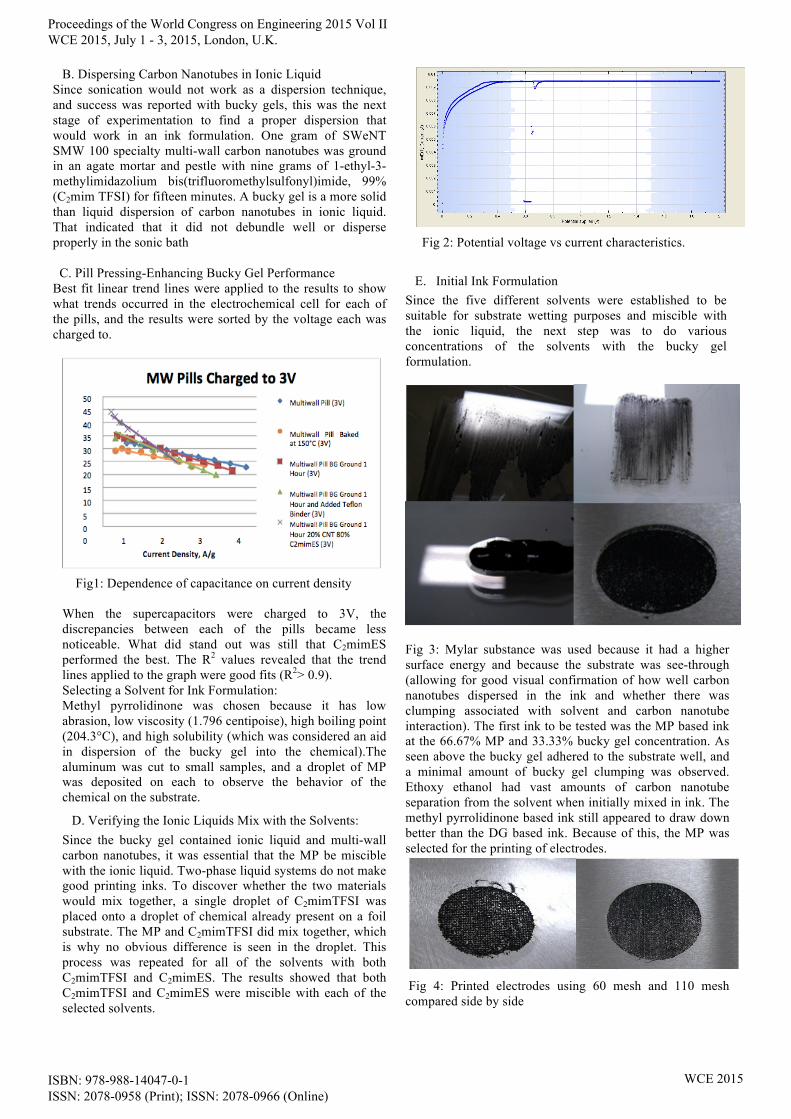
B. Dispersing Carbon Nanotubes in Ionic Liquid Since sonication would not work as a dispersion technique, and success was reported with bucky gels, this was the next stage of experimentation to find a proper dispersion that would work in an ink formulation. One gram of SWeNT SMW 100 specialty multi-wall carbon nanotubes was ground in an agate mortar and pestle with nine grams of 1-ethyl-3-methylimidazolium bis(trifluoromethylsulfonyl)imide, 99% (C2mim TFSI) for fifteen minutes. A bucky gel is a more solid than liquid dispersion of carbon nanotubes in ionic liquid. That indicated that it did not debundle well or disperse properly in the sonic bath C. Pill Pressing-Enhancing Bucky Gel Performance Best fit linear trend lines were applied to the results to show what trends occurred in the electrochemical cell for each of the pills, and the results were sorted by the voltage each was charged to.
Fig1: Dependence of capacitance on current density When the supercapacitors were charged to 3V, the discrepancies between each of the pills became less noticeable. What did stand out was still that C2mimES performed the best. The R2 values revealed that the trend lines applied to the graph were good fits (R2> 0.9). Selecting a Solvent for Ink Formulation: Methyl pyrrolidinone was chosen because it has low abrasion, low viscosity (1.796 centipoise), high boiling point (204.3°C), and high solubility (which was considered an aid in dispersion of the bucky gel into the chemical).The aluminum was cut to small samples, and a droplet of MP was deposited on each to observe the behavior of the chemical on the substrate.
D. Verifying the Ionic Liquids Mix with the Solvents: Since the bucky gel contained ionic liquid and multi-wall carbon nanotubes, it was essential that the MP be miscible with the ionic liquid. Two-phase liquid systems do not make good printing inks. To discover whether the two materials would mix together, a single droplet of C2mimTFSI was placed onto a droplet of chemical already present on a foil substrate. The MP and C2mimTFSI did mix together, which is why no obvious difference is seen in the droplet. This process was repeated for all of the solvents with both C2mimTFSI and C2mimES. The results showed that both C2mimTFSI and C2mimES were miscible with each of the selected solvents.
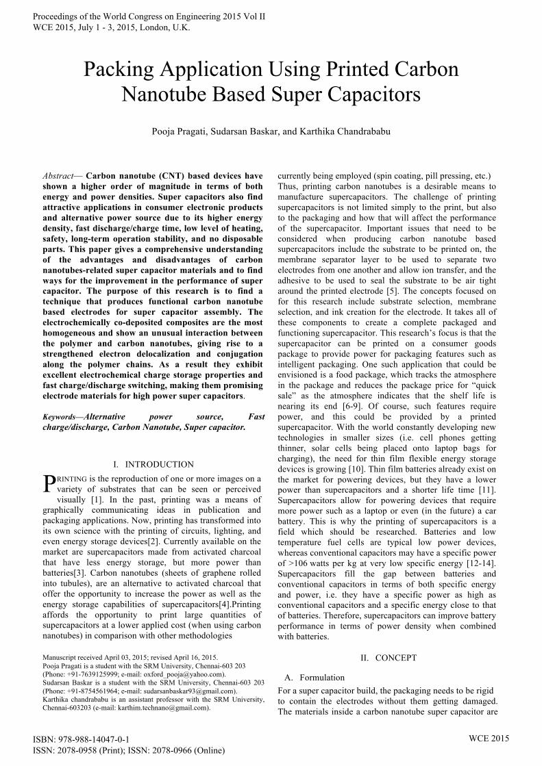
Fig 2: Potential voltage vs current characteristics.
E. Initial Ink Formulation Since the five different solvents were established to be suitable for substrate wetting purposes and miscible with the ionic liquid, the next step was to do various concentrations of the solvents with the bucky gel formulation.
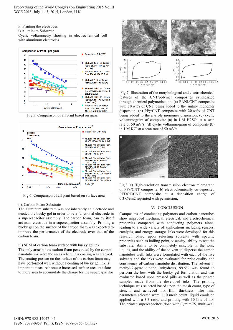
Fig 3: Mylar substance was used because it had a higher surface energy and because the substrate was see-through (allowing for good visual confirmation of how well carbon nanotubes dispersed in the ink and whether there was clumping associated with solvent and carbon nanotube interaction). The first ink to be tested was the MP based ink at the 66.67% MP and 33.33% bucky gel concentration. As seen above the bucky gel adhered to the substrate well, and a minimal amount of bucky gel clumping was observed. Ethoxy ethanol had vast amounts of carbon nanotube separation from the solvent when initially mixed in ink. The methyl pyrrolidinone based ink still appeared to draw down better than the DG based ink. Because of this, the MP was selected for the printing of electrodes.
Fig 4: Printed electrodes using 60 mesh and 110 mesh compared side by side
Proceedings of the World Congress on Engineering 2015 Vol II WCE 2015, July 1 - 3, 2015, London, U.K.
ISBN: 978-988-14047-0-1 ISSN: 2078-0958 (Print); ISSN: 2078-0966 (Online)
WCE 2015
F. Printing the electrodes i) Aluminum Substrate Cyclic voltammetry shorting in electrochemical cell with aluminum electrodes
Fig 5: Comparison of all print based on mass
Fig 6: Comparison of all print based on surface area ii). Carbon Foam Substrate The aluminum substrate was not inherently an electrode and needed the bucky gel in order to be a functional electrode in a supercapacitor assembly. The carbon foam, can by itself act asan electrode in a supercapacitor assembly. Printing a bucky gel on the surface of the carbon foam was expected to improve the performance of the electrode over that of the carbon foam. iii) SEM of carbon foam surface with bucky gel ink The only areas of the carbon foam penetrated by the carbon nanotube ink were the areas where this coating was cracked. The coating present on the surface of the carbon foam may have performed well without a coating of bucky gel ink is important measure because increased surface area translates to more area to accumulate the charge for the supercapacitor
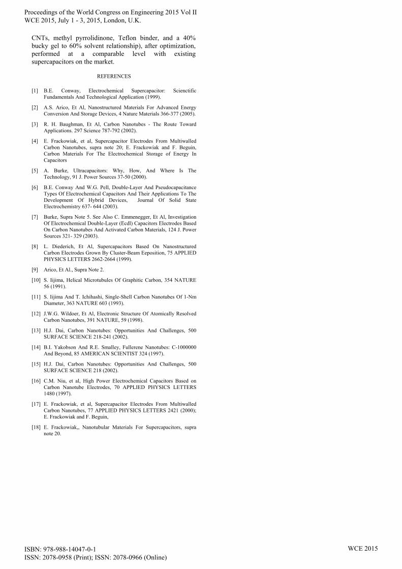
Fig.7: Illustration of the morphological and electrochemical features of the CNT/polymer composites synthesized through chemical polymerisation. (a) PANI/CNT composite with 10 wt% of CNT being added to the aniline monomer dispersion; (b) PPy/CNT composite with 20 wt% of CNT being added to the pyrrole monomer dispersion; (c) cyclic voltammogram of composite (a) in 1 M H2SO4 at a scan rate of 50 mV/s; (d) cyclic voltammogram of composite (b) in 1 M KCl at a scan rate of 50 mV/s.
Fig.8 (a) High-resolution transmission electron micrograph of PPy/CNT composite. b) electrochemically co-deposited PEDOT/CNT composite at a deposition charge of 0.3 C/cm2 reprinted with permission.
V. CONCLUSION Composites of conducting polymers and carbon nanotubes show improved mechanical, electrical, and electrochemical properties compared with conducting polymers alone, leading to a wide variety of applications including sensors, catalysis, and energy storage. Inks were developed for this research based upon selecting solvents with specific properties such as boiling point, viscosity, ability to wet the substrate, ability to be completely miscible in the ionic liquids, and the ability of the solvent to disperse the carbon nanotubes well. Inks were formulated with each of the five solvents and the inks were evaluated for print quality and consistency of carbon nanotube distribution. The solvent 1-methyl-2-pyrrolidinone, anhydrous, 99.5% was found to perform the best with the bucky gel formulation and was evaluated based upon pressed pills as well as the printed samples made from the developed inks. The printing technique was selected based upon the mesh count, type of stencil, and achieved ink film thickness. The final parameters selected were: 110 mesh count, liquid emulsion applied with a 3:3 ratio, and printing with 10 hits of ink. The printed supercapacitor (done with C2mimES, multi-wall
Proceedings of the World Congress on Engineering 2015 Vol II WCE 2015, July 1 - 3, 2015, London, U.K.
ISBN: 978-988-14047-0-1 ISSN: 2078-0958 (Print); ISSN: 2078-0966 (Online)
WCE 2015
CNTs, methyl pyrrolidinone, Teflon binder, and a 40% bucky gel to 60% solvent relationship), after optimization, performed at a comparable level with existing supercapacitors on the market.
REFERENCES
[1] B.E. Conway, Electrochemical Supercapacitor: Scienctific Fundamentals And Technological Application (1999).
[2] A.S. Arico, Et Al, Nanostructured Materials For Advanced Energy Conversion And Storage Devices, 4 Nature Materials 366-377 (2005).
[3] R. H. Baughman, Et Al, Carbon Nanotubes - The Route Toward Applications. 297 Science 787-792 (2002).
[4] E. Frackowiak, et al, Supercapacitor Electrodes From Multiwalled Carbon Nanotubes, supra note 20; E. Frackowiak and F. Beguin, Carbon Materials For The Electrochemical Storage of Energy In Capacitors
[5] A. Burke, Ultracapacitors: Why, How, And Where Is The Technology, 91 J. Power Sources 37-50 (2000).
[6] B.E. Conway And W.G. Pell, Double-Layer And Pseudocapacitance Types Of Electrochemical Capacitors And Their Applications To The Development Of Hybrid Devices, Journal Of Solid State Electrochemistry 637- 644 (2003).
[7] Burke, Supra Note 5. See Also C. Emmenegger, Et Al, Investigation Of Electrochemical Double-Layer (Ecdl) Capacitors Electrodes Based On Carbon Nanotubes And Activated Carbon Materials, 124 J. Power Sources 321- 329 (2003).
[8] L. Diederich, Et Al, Supercapacitors Based On Nanostructured Carbon Electrodes Grown By Cluster-Beam Eeposition, 75 APPLIED PHYSICS LETTERS 2662-2664 (1999).
[9] Arico, Et Al., Supra Note 2.
[10] S. Iijima, Helical Microtubules Of Graphitic Carbon, 354 NATURE 56 (1991).
[11] S. Iijima And T. Ichihashi, Single-Shell Carbon Nanotubes Of 1-Nm Diameter, 363 NATURE 603 (1993).
[12] J.W.G. Wildoer, Et Al, Electronic Structure Of Atomically Resolved Carbon Nanotubes, 391 NATURE, 59 (1998).
[13] H.J. Dai, Carbon Nanotubes: Opportunities And Challenges, 500 SURFACE SCIENCE 218-241 (2002).
[14] B.I. Yakobson And R.E. Smalley, Fullerene Nanotubes: C-1000000 And Beyond, 85 AMERICAN SCIENTIST 324 (1997).
[15] H.J. Dai, Carbon Nanotubes: Opportunities And Challenges, 500 SURFACE SCIENCE 218 (2002).
[16] C.M. Niu, et al, High Power Electrochemical Capacitors Based on Carbon Nanotube Electrodes, 70 APPLIED PHYSICS LETTERS 1480 (1997).
[17] E. Frackowiak, et al, Supercapacitor Electrodes From Multiwalled Carbon Nanotubes, 77 APPLIED PHYSICS LETTERS 2421 (2000); E. Frackowiak and F. Beguin,
[18] E. Frackowiak,, Nanotubular Materials For Supercapacitors, supra note 20.
Proceedings of the World Congress on Engineering 2015 Vol II WCE 2015, July 1 - 3, 2015, London, U.K.
ISBN: 978-988-14047-0-1 ISSN: 2078-0958 (Print); ISSN: 2078-0966 (Online)
WCE 2015