Embed Size (px)
Citation preview

GE Intelligent Platforms
Programmable Control Products
PACSystems* Controllers Battery and Energy Pack Manual GFK-2741D June 2015

Legal Information
GFL-002 Warnings, Cautions, and Notes as Used in this Publication
Warning
Warning notices are used in this publication to emphasize that hazardous voltages, currents, temperatures, or other conditions that could cause personal injury exist in this equipment or may be associated with its use. In situations where inattention could cause either personal injury or damage to equipment, a Warning notice is used.
Caution
Caution notices are used where equipment might be damaged if care is not taken.
Note: Notes merely call attention to information that is especially significant to understanding and operating the equipment.
These instructions do not purport to cover all details or variations in equipment, nor to provide for every possible contingency to be met during installation, operation, and maintenance. The information is supplied for informational purposes only, and GE makes no warranty as to the accuracy of the information included herein. Changes, modifications, and/or improvements to equipment and specifications are made periodically and these changes may or may not be reflected herein. It is understood that GE may make changes, modifications, or improvements to the equipment referenced herein or to the document itself at any time. This document is intended for trained personnel familiar with the GE products referenced herein.
GE may have patents or pending patent applications covering subject matter in this document. The furnishing of this document does not provide any license whatsoever to any of these patents.
GE PROVIDES THE FOLLOWING DOCUMENT AND THE INFORMATION INCLUDED THEREIN AS-IS AND WITHOUT WARRANTY OF ANY KIND, EXPRESSED OR IMPLIED, INCLUDING BUT NOT LIMITED TO ANY IMPLIED STATUTORY WARRANTY OF MERCHANTABILITY OR FITNESS FOR PARTICULAR PURPOSE.
* indicates a trademark of GE Intelligent Platforms, Inc. and/or its affiliates. All other trademarksare the property of their respective owners.
©Copyright 2013-2015 General Electric Company. All Rights Reserved
If you purchased this product through an Authorized Channel Partner, please contact the seller directly.
Contact Information
If you purchased this product through an Authorized Channel Partner, please contact the seller directly.
General Contact Information
Online technical support and GlobalCare http://support.ge-ip.com
Additional information http://www.ge-ip.com/
Solution Provider [email protected]
Technical Support
If you have technical problems that cannot be resolved with the information in this guide, please contact us by
telephone or email, or on the web at http://support.ge-ip.com
Americas
Online Technical Support www.ge-ip.com/support
Phone 1-800-433-2682
International Americas Direct Dial 1-780-420-2010 (if toll free 800 option is unavailable)
Technical Support Email [email protected]
Customer Care Email [email protected]
Primary language of support English
Europe, the Middle East, and Africa
Online Technical Support www.ge-ip.com/support
Phone +800-1-433-2682
EMEA Direct Dial +420-23-901-5850 (if toll free 800 option is unavailable or dialing
from a mobile telephone)
Technical Support Email [email protected]
Customer Care Email [email protected]
Primary languages of support English, French, German, Italian, Czech, Spanish
Asia Pacific
Online Technical Support www.ge-ip.com/support
Phone +86-400-820-8208
+86-21-3217-4826 (India, Indonesia, and Pakistan)
Technical Support Email [email protected] (China)
[email protected] (Japan)
[email protected] (remaining Asia customers)
Customer Care Email [email protected]
[email protected] (China)

Contents
GFK-2741D June 2015 i
1. Introduction ..................................................................................................................................................... 1
2. Batteries............................................................................................................................................................ 3
2.1 Battery Selection .......................................................................................................................................................................................... 3 2.1.1 Conventional Coin-Cell Lithium Battery (IC698ACC701A, IC698ACC701B) ........................................................ 3 2.1.2 Conventional Auxiliary Battery (IC693ACC302) ................................................................................................................ 3 2.1.3 Smart Coin-Cell Lithium Battery (IC698ACC701, revision C & later) ...................................................................... 3 2.1.4 Smart Auxiliary Lithium Battery (IC695ACC302) .............................................................................................................. 3 2.1.5 Rechargeable Battery (IC690RBT001) ................................................................................................................................... 3
2.2 Battery Compatibility and Memory Retention Time in Days at 20°C ................................................................................ 4 2.3 CPU Support of Low Battery Detection ............................................................................................................................................ 5 2.4 Smart Batteries ............................................................................................................................................................................................. 6
2.4.1 Smart Battery Operation .............................................................................................................................................................. 6 2.4.2 IC695ACC302 ...................................................................................................................................................................................... 7
2.4.2.1 Specifications ......................................................................................................................................................................... 7 2.4.2.2 Battery Mounting ................................................................................................................................................................. 7
2.4.3 IC698ACC701C (& later revisions) ............................................................................................................................................ 8 2.4.3.1 Specifications ......................................................................................................................................................................... 8
2.5 Rechargeable Batteries ............................................................................................................................................................................ 9 2.5.1 IC690RBT001 ...................................................................................................................................................................................... 9
2.5.1.1 Specifications ......................................................................................................................................................................... 9 2.5.1.2 Nominal Battery Life .......................................................................................................................................................... 9 2.5.1.3 Battery Mounting ................................................................................................................................................................. 9 2.5.1.4 CPU Battery Low Indication ......................................................................................................................................... 10 2.5.1.5 Diagnostics ........................................................................................................................................................................... 10
2.5.2 IC690CRG001 ................................................................................................................................................................................... 10 2.5.2.1 Specifications ....................................................................................................................................................................... 10 2.5.2.2 Operation ............................................................................................................................................................................... 10 2.5.2.3 Indicators ............................................................................................................................................................................... 10 2.5.2.4 Charger Connection ......................................................................................................................................................... 11
2.6 Legacy Batteries ......................................................................................................................................................................................... 11 2.6.1 IC698ACC701A and IC698ACC701B ..................................................................................................................................... 11
2.6.1.1 Specifications ....................................................................................................................................................................... 11 2.6.1.2 CPU Battery Low Indication ......................................................................................................................................... 11
2.6.2 IC693ACC302 .................................................................................................................................................................................... 12 2.6.2.1 Specifications ....................................................................................................................................................................... 12 2.6.2.2 Battery Mounting ............................................................................................................................................................... 12 2.6.2.3 CPU Battery Low Indication ......................................................................................................................................... 12 2.6.2.4 Diagnostics ........................................................................................................................................................................... 12
2.7 Battery Installation Instructions ......................................................................................................................................................... 13 2.7.1 Installation in Hazardous Areas ............................................................................................................................................. 13 2.7.2 Preparation and Mounting ........................................................................................................................................................ 13 2.7.3 Installation and Replacement ................................................................................................................................................. 13
2.8 Date Code & Shelf Life ............................................................................................................................................................................. 15 2.9 Safe Handling & Disposal ...................................................................................................................................................................... 15 2.10 Agency Certifications ............................................................................................................................................................................... 16
2.10.1 Batteries .............................................................................................................................................................................................. 16 2.10.2 Charger: IC690CRG001 ............................................................................................................................................................... 16
Contents
ii PACSystems* Controllers Battery and Energy Pack Manual GFK-2741D
3. Energy Packs ................................................................................................................................................. 17
3.1 Energy Pack Compatibility .................................................................................................................................................................... 17 3.2 PACSystems RXi Energy Pack (ICRXIACCEPK01A) ..................................................................................................................... 17
3.2.1 Specifications ................................................................................................................................................................................... 17 3.2.2 General Installation Environments ....................................................................................................................................... 18 3.2.3 Industrial Environment Installations .................................................................................................................................... 18 3.2.4 Hardware Installation .................................................................................................................................................................. 18
3.2.4.1 Mounting the Energy Pack on a DIN Rail .............................................................................................................. 18 3.2.4.2 Mounting the Energy Pack Directly on a Panel .................................................................................................. 19
3.2.5 Cable Connections ......................................................................................................................................................................... 20 3.2.5.1 Connecting Input Power to the Energy Pack ...................................................................................................... 20 3.2.5.2 Connecting the Energy Pack to the Controller ................................................................................................... 21
3.2.6 Grounding .......................................................................................................................................................................................... 21 3.2.7 Power-up ............................................................................................................................................................................................ 22 3.2.8 LED Indications ................................................................................................................................................................................ 22
3.2.8.1 LED Indications: Special Cases ................................................................................................................................... 22 3.2.9 Backup Operation .......................................................................................................................................................................... 22 3.2.10 Service and Maintenance .......................................................................................................................................................... 23
3.2.10.1 Replacing the Cap Pack Module ................................................................................................................................ 23 3.2.10.2 Firmware Updates............................................................................................................................................................. 23
3.2.11 Diagnostics ........................................................................................................................................................................................ 24 3.2.11.1 System Version Information ........................................................................................................................................ 24 3.2.11.2 Status Information ............................................................................................................................................................ 24 3.2.11.3 Energy Pack LEDs .............................................................................................................................................................. 24
3.2.12 Agency Certifications ................................................................................................................................................................... 24 3.3 PACSystems RX3i Energy Pack (IC695ACC400) .......................................................................................................................... 24 3.4 PACSystems RX3i Energy Pack (IC695ACC402) .......................................................................................................................... 24
4. Related Documents ..................................................................................................................................... 25

Introduction
GFK-2741D June 2015 1
1. Introduction
Many PACSystems CPUs require a battery or energy pack to back up volatile memory. This memory is separate
from the non-volatile flash memory. This manual covers the technologies used to back up volatile memory on
PACSystems RX3i and RX7i CPUs, and RXi Controllers. Other GE Intelligent Platforms manuals and documents
discuss memory retention technologies in passing. However, when it comes to energy sources used by PACSystems
to back up volatile memory, this manual should be considered the definitive source.
Other methods of retaining volatile memory, such as real-time clock batteries, are not covered by this manual.
Note, however, that RX7i CPUs use the same battery mechanism to back up the calendar clock and user memory.
This manual includes:
A battery selection guide, information on battery life and usage, disposal instructions, and agency
compliance
RXi Energy Pack specifications, installation, operation, and service and maintenance

Introduction
2 PACSystems* Controllers Battery and Energy Pack Manual GFK-2741D

Batteries
GFK-2741D June 2015 3
2. Batteries
2.1 Battery Selection
2.1.1 Conventional Coin-Cell Lithium Battery (IC698ACC701A, IC698ACC701B)
The conventional coin-cell lithium batteries are relatively small and have the advantage of fitting inside the battery
compartment of compatible CPUs. The disadvantages are limited memory retention time, limited CPU compatibility,
and no support for low battery detection.
2.1.2 Conventional Auxiliary Battery (IC693ACC302)
The conventional auxiliary battery should be used where maximum memory retention time is desired. It is
compatible with all PACSystems CPUs requiring a battery for memory retention and no other battery has a better
memory retention time. The disadvantages are that external mounting is required due to battery size and it does
not support low battery detection.
2.1.3 Smart Coin-Cell Lithium Battery (IC698ACC701, revision C & later)
The smart coin-cell lithium battery is an improvement on the conventional coin-cell lithium battery and adds
reliable low battery detection for compatible CPUs at the expense of reduced memory retention time. The improved
battery is slightly larger, but is still able to fit into the battery compartment of compatible CPUs. The disadvantages
are reduced memory retention time as compared to conventional batteries and limited CPU compatibility. For CPUs
that do not support low battery detection, the conventional coin-cell lithium battery may be a better choice as it will
provide longer retention time.
2.1.4 Smart Auxiliary Lithium Battery (IC695ACC302)
The smart auxiliary lithium battery is an improvement on the conventional auxiliary lithium battery and adds
reliable low battery detection for compatible CPUs at the expense of a slight reduction in memory retention time.
The disadvantage is that external mounting is required due to battery size. For CPUs that do not support low
battery detection, the conventional auxiliary lithium battery may be a better choice as it will provide longer
retention time.
2.1.5 Rechargeable Battery (IC690RBT001)
The rechargeable battery is designed for customer applications that use memory retention on a cyclical basis.
Customers who shut down equipment and rely on battery backed memory on a daily or weekly basis should
consider the use of this battery. It is compatible with all PACSystems CPUs requiring a battery for memory retention
and is slightly larger than the auxiliary lithium batteries. The disadvantages are that external mounting is required
due to battery and charger size, no support for low battery detection, limited temperature range (0°C – 50°C), and
inability to charge in a hazardous location.
Batteries
4 PACSystems* Controllers Battery and Energy Pack Manual GFK-2741D
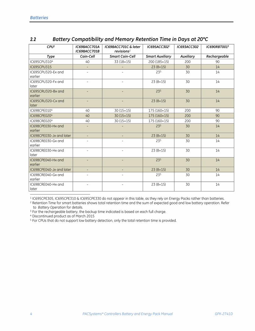
2.2 Battery Compatibility and Memory Retention Time in Days at 20°C
CPU1 IC698ACC701A IC698ACC701B
IC698ACC701C & later revisions2
IC695ACC3022 IC693ACC302 IC690RBT0013
Type Coin-Cell Smart Coin-Cell Smart Auxiliary Auxiliary Rechargeable
IC695CPU3104 40 33 (18+15) 200 (185+15) 200 90
IC695CPU315 - - 23 (8+15) 30 14
IC695CPU320-Ex and earlier
- - 235 30 14
IC695CPU320-Fx and later
- - 23 (8+15) 30 14
IC695CRU320-Bx and earlier
- - 235 30 14
IC695CRU320-Cx and later
- - 23 (8+15) 30 14
IC698CPE0104 40 30 (15+15) 175 (160+15) 200 90
IC698CPE0204 40 30 (15+15) 175 (160+15) 200 90
IC698CRE0204 40 30 (15+15) 175 (160+15) 200 90
IC698CPE030-Hx and earlier
- - 235 30 14
IC698CPE030-Jx and later - - 23 (8+15) 30 14
IC698CRE030-Gx and earlier
- - 235 30 14
IC698CRE030-Hx and later
- - 23 (8+15) 30 14
IC698CPE040-Hx and earlier
- - 235 30 14
IC698CPE040-Jx and later - - 23 (8+15) 30 14
IC698CRE040-Gx and earlier
- - 235 30 14
IC698CRE040-Hx and later
- - 23 (8+15) 30 14
1 IC695CPE305, IC695CPE310 & IC695CPE330 do not appear in this table, as they rely on Energy Packs rather than batteries. 2 Retention Time for smart batteries shows total retention time and the sum of expected good and low battery operation. Refer
to Battery Operation for details. 3 For the rechargeable battery, the backup time indicated is based on each full charge. 4 Discontinued product as of March 2015 5 For CPUs that do not support low battery detection, only the total retention time is provided.
Batteries
GFK-2741D June 2015 5
2.3 CPU Support of Low Battery Detection
For low battery detection to work reliably, a smart battery (IC695ACC302 and IC698ACC701 revision C or later) must
be used with a CPU that supports low battery detection, such as the following:
IC695CPU3104 all hardware and firmware versions
IC695CPU315 all hardware and firmware versions
IC695CPU320-Fx and later hardware revisions with firmware revision 6.02 or later
IC695CRU320-Cx and later hardware revisions with firmware revision 6.02 or later
IC698CPE0104 all hardware and firmware versions
IC698CPE0204 all hardware and firmware versions
IC698CRE0204 all hardware and firmware versions
IC698CPE030-Jx and later hardware revisions with firmware revision 6.75 or later
IC698CPE040-Jx and later hardware revisions with firmware revision 6.75 or later
IC698CRE030-Hx and later hardware revisions with firmware revision 6.75 or later
IC698CRE040-Hx and later hardware revisions with firmware revision 6.75 or later
The use of a non-smart battery or a CPU not on the above list will result in the low battery detection bits being
unreliable.
Low/failed battery conditions are indicated by CPU LED operation and %S status bits. For details, refer to
Diagnostics in the PACSystems RX7i & RX3i CPU Reference Manual, GFK-2222.
Batteries
6 PACSystems* Controllers Battery and Energy Pack Manual GFK-2741D
2.4 Smart Batteries
2.4.1 Smart Battery Operation
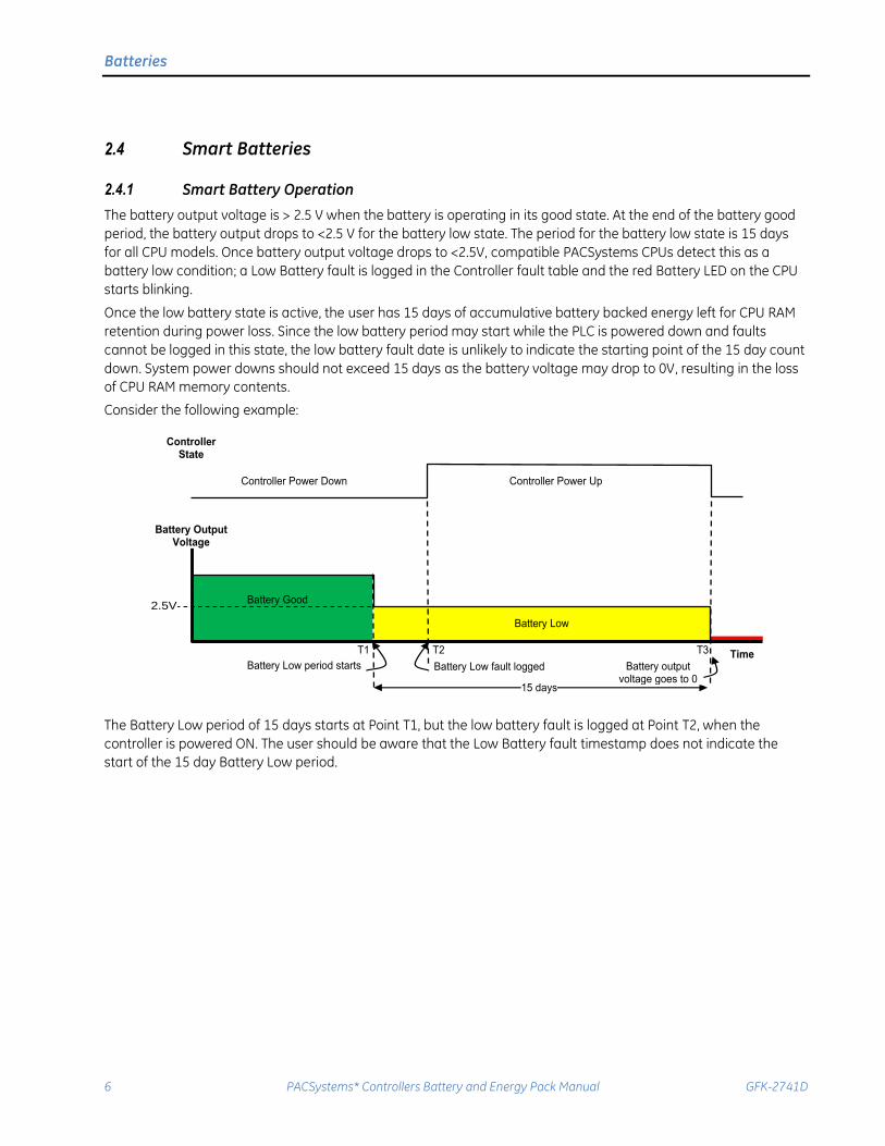
The battery output voltage is > 2.5 V when the battery is operating in its good state. At the end of the battery good
period, the battery output drops to <2.5 V for the battery low state. The period for the battery low state is 15 days
for all CPU models. Once battery output voltage drops to <2.5V, compatible PACSystems CPUs detect this as a
battery low condition; a Low Battery fault is logged in the Controller fault table and the red Battery LED on the CPU
starts blinking.
Once the low battery state is active, the user has 15 days of accumulative battery backed energy left for CPU RAM
retention during power loss. Since the low battery period may start while the PLC is powered down and faults
cannot be logged in this state, the low battery fault date is unlikely to indicate the starting point of the 15 day count
down. System power downs should not exceed 15 days as the battery voltage may drop to 0V, resulting in the loss
of CPU RAM memory contents.
Consider the following example:
Battery Good
Battery Low
Controller Power Down Controller Power Up
T1 T2 Battery Low period starts Battery Low fault logged
Time
Controller State
15 days
T3
Battery output voltage goes to 0
2.5V
Battery Output Voltage
The Battery Low period of 15 days starts at Point T1, but the low battery fault is logged at Point T2, when the
controller is powered ON. The user should be aware that the Low Battery fault timestamp does not indicate the
start of the 15 day Battery Low period.
Batteries
GFK-2741D June 2015 7
2.4.2 IC695ACC302
The IC695ACC302 Auxiliary Smart Battery Module is an enhanced version of IC693ACC302. In addition to providing an extended backup time for volatile memory on PACSystems CPUs compared to the standard memory backup battery (IC698ACC701), the smart battery module has a battery monitoring circuit that enables the user to detect the low battery state before it is completely drained. Once an IC695ACC302 Auxiliary Smart Battery Module is connected to a CPU model, it must be used with only that specific CPU model for the remainder of its life to insure proper Low Battery indication. IC695ACC302 Auxiliary Smart Battery Modules should be replaced every 2 years or once a Low Battery fault is logged in the CPU, whichever occurs first.
2.4.2.1 Specifications
Parameter Specification
Battery capacity 15.0 Amp-hours
Lithium content 5.1 grams (3 cells @ 1.7 grams/cell)
Physical dimensions 5.713” long x 2.559” wide x 1.571” high (145.1 x 65.0 x 39.9 mm)
Weight 224 grams
Case material Black, flame-retardant ABS plastic
Connection 2’ (60cm) twisted red/black 22 AWG (0.326mm2) cable with female two-pin connector compatible with the battery connector on PAC Systems CPUs.
Operating temperature range 0 to +60ºC
Nominal shelf life 7 years @ 20ºC without the enabling adapter cable attached
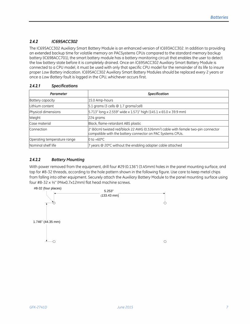
2.4.2.2 Battery Mounting
With power removed from the equipment, drill four #29 (0.136”) (3.45mm) holes in the panel mounting surface, and
tap for #8-32 threads, according to the hole pattern shown in the following figure. Use care to keep metal chips
from falling into other equipment. Securely attach the Auxiliary Battery Module to the panel mounting surface using
four #8-32 x ½” (M4x0.7x12mm) flat head machine screws.
5.253"
(133.43 mm)
1.746" (44.35 mm)
#8-32 (four places)

Batteries
8 PACSystems* Controllers Battery and Energy Pack Manual GFK-2741D
2.4.3 IC698ACC701C (& later revisions)
The IC698ACC701C smart coin cell battery pack is an enhanced version of the IC698ACC701B battery pack. In
addition to providing volatile memory backup for PACSystems CPUs, the smart coin cell battery pack has a battery
monitoring circuit that enables the user to detect the low battery state before it is completely drained. Once an
IC698ACC701C smart coin cell battery pack is connected to a CPU model, it must be used with only that specific
CPU model for the remainder of its life to insure proper Low Battery indication. IC698ACC701C smart coin cell
battery packs should be replaced every 2 years or once a Low Battery fault is logged in the CPU, whichever occurs
first.
2.4.3.1 Specifications
Parameter Specification
Battery capacity 3.0 Amp-hours
Lithium content 0.87 grams (3 cells @0.29grams/cell)
Physical dimensions 3” long x 1.059” wide x 0.4822” high (76.2 x 26.92 x 12.25mm)
Weight 29.94 grams
Connection 2’ (60cm) twisted red/black 22 AWG (0.326mm2) cable with female two-pin connector compatible with the battery connector on PAC Systems CPUs.
Operating temperature range 0 to +60ºC
Nominal shelf life 5 years @ 20ºC without the enabling adapter cable attached
Batteries
GFK-2741D June 2015 9
2.5 Rechargeable Batteries
2.5.1 IC690RBT001
The IC690RBT001 Rechargeable Battery provides an extended backup time for volatile memory on PACSystems
CPUs compared to that of the standard memory backup battery (IC698ACC701).
2.5.1.1 Specifications
Parameter Specification
Battery capacity 7.0 Amp-hours
Battery construction 3-cell, nickel-metal hydride
Lithium content None
Physical dimensions 6.902” long x 3.150” wide x 1.819” high (175.3 x 80.0 x 46.2 mm)
Case material Black, flame-retardant ABS plastic
Connection 2’ (60cm) twisted red/black 22 AWG (0.326mm2) cable with female two-pin connector compatible with the battery connector on PACSystems CPUs.
Operating temperature range 0 to +50ºC
Nominal shelf life 3 years@ 20ºC
Operating life @ 50ºC 12 months or 60 charge-discharge cycles
Compatible Charger IC690CRG001
2.5.1.2 Nominal Battery Life
The nominal battery life at 50ºC is 12 months or 60 charge/discharge cycles. Battery life is negatively affected by
higher temperatures, and can be significantly improved by operating closer to room temperature (25ºC). When
deciding where to mount the battery, consider how the mounting location will affect the battery temperature. For
most industrial installations, mounting the battery below the PLC rack will result in a temperature closer to 25ºC
and will help improve battery life. Do not operate the battery at less than 0ºC or greater than 50ºC.
The battery will continue to operate after 12 months or 60 charge/discharge cycles, however the battery capacity
will decline and the times listed in the Battery Compatibility and Memory Retention Time in Days at 20°C chart will no
longer be valid.
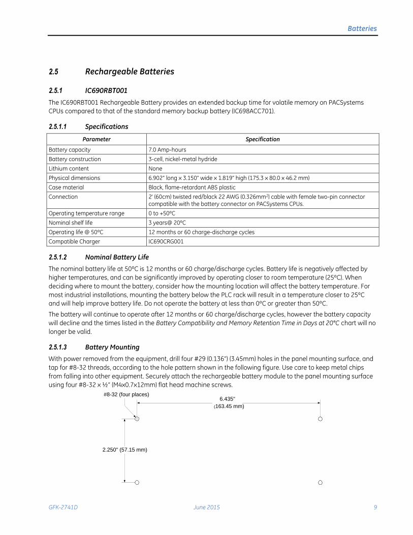
2.5.1.3 Battery Mounting
With power removed from the equipment, drill four #29 (0.136”) (3.45mm) holes in the panel mounting surface, and
tap for #8-32 threads, according to the hole pattern shown in the following figure. Use care to keep metal chips
from falling into other equipment. Securely attach the rechargeable battery module to the panel mounting surface
using four #8-32 x ½” (M4x0.7x12mm) flat head machine screws.
6.435"
(163.45 mm)
2.250" (57.15 mm)
#8-32 (four places)
Batteries
10 PACSystems* Controllers Battery and Energy Pack Manual GFK-2741D
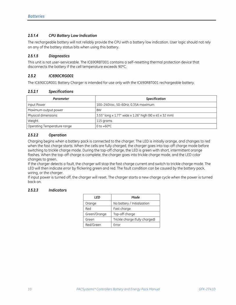
2.5.1.4 CPU Battery Low Indication
The rechargeable battery will not reliably provide the CPU with a battery low indication. User logic should not rely
on any of the battery status bits when using this battery.
2.5.1.5 Diagnostics
This unit is not user-serviceable. The IC690RBT001 contains a self-resetting thermal protection device that disconnects the battery if the cell temperature exceeds 90ºC.
2.5.2 IC690CRG001
The IC690CGR001 Battery Charger is intended for use only with the IC690RBT001 rechargeable battery.
2.5.2.1 Specifications
Parameter Specification
Input Power 100–240Vac, 50–60Hz, 0.35A maximum
Maximum output power 8W
Physical dimensions 3.55” long x 1.77” wide x 1.26” high (90 x 45 x 32 mm)
Weight 115 grams
Operating Temperature range 0 to +60ºC
2.5.2.2 Operation
Charging begins when a battery pack is connected to the charger. The LED is initially orange, and changes to red when the fast charge starts. When the cells are fully charged, the charger goes into top-off charge mode before switching to trickle charge mode. During the top-off charge, the LED is green with short, intermittent orange flashes. When the top-off charge is complete, the charger goes into trickle charge mode, and the LED color changes to green. If the charger detects a fault, the charger will stop the fast charge current and switch to trickle charge mode. The LED will then indicate error by flickering green and red. The fault condition can be caused by the battery pack, wiring, or the charger. If input power is turned off, the charger will reset. The charger starts a new charge cycle when the power is turned back on.
2.5.2.3 Indicators
LED Mode
Orange No battery / Initialization
Red Fast charge
Green/Orange Top-off charge
Green Trickle charge (fully charged)
Red/Green Error

Batteries
GFK-2741D June 2015 11
2.5.2.4 Charger Connection
Warning
Explosion Hazard - Recharge battery only in a non-hazardous location. Do not connect or disconnect the battery charger unless the area is known to be non-hazardous. The IC690CRG001 battery charger is not certified for use in hazardous locations.
Insert the charging jack into the threaded connector on the side of the battery and hand-tighten the screw lock to
secure it.
2.6 Legacy Batteries
2.6.1 IC698ACC701A and IC698ACC701B
The IC698ACC701B (and earlier revisions) coin cell battery pack is a simple battery pack that provides backup for
volatile memory on PACSystems CPUs. The chemistry used in these batteries does not support the low-battery
detection feature. Due to the limited capacity of this battery pack, it is not compatible with all PACSystems CPUs.
Please refer to the Battery Compatibility and Memory Retention Time in Days at 20°C chart for CPU compatibility
information.
2.6.1.1 Specifications
Parameter Specification
Battery capacity 3.0 Amp-hours
Lithium (Li) content 0.87 grams (3 cells @ 0.29grams/cell)
Physical dimensions 3” long x 1.059” wide x 0.4822” high (76.2 x 26.92 x 12.25mm)
Weight 26.5 grams
Connection 2’ (60cm) twisted red/black 22 AWG (0.326mm2) cable with female two-pin connector compatible with the battery connector on PAC Systems CPUs.
Operating temperature range 0 to +60ºC
Nominal shelf life 5 years @ 20ºC
2.6.1.2 CPU Battery Low Indication
The legacy batteries will not reliably provide the CPU with a battery low indication. User logic should not rely on any
of the battery status bits when using these batteries.
Batteries
12 PACSystems* Controllers Battery and Energy Pack Manual GFK-2741D
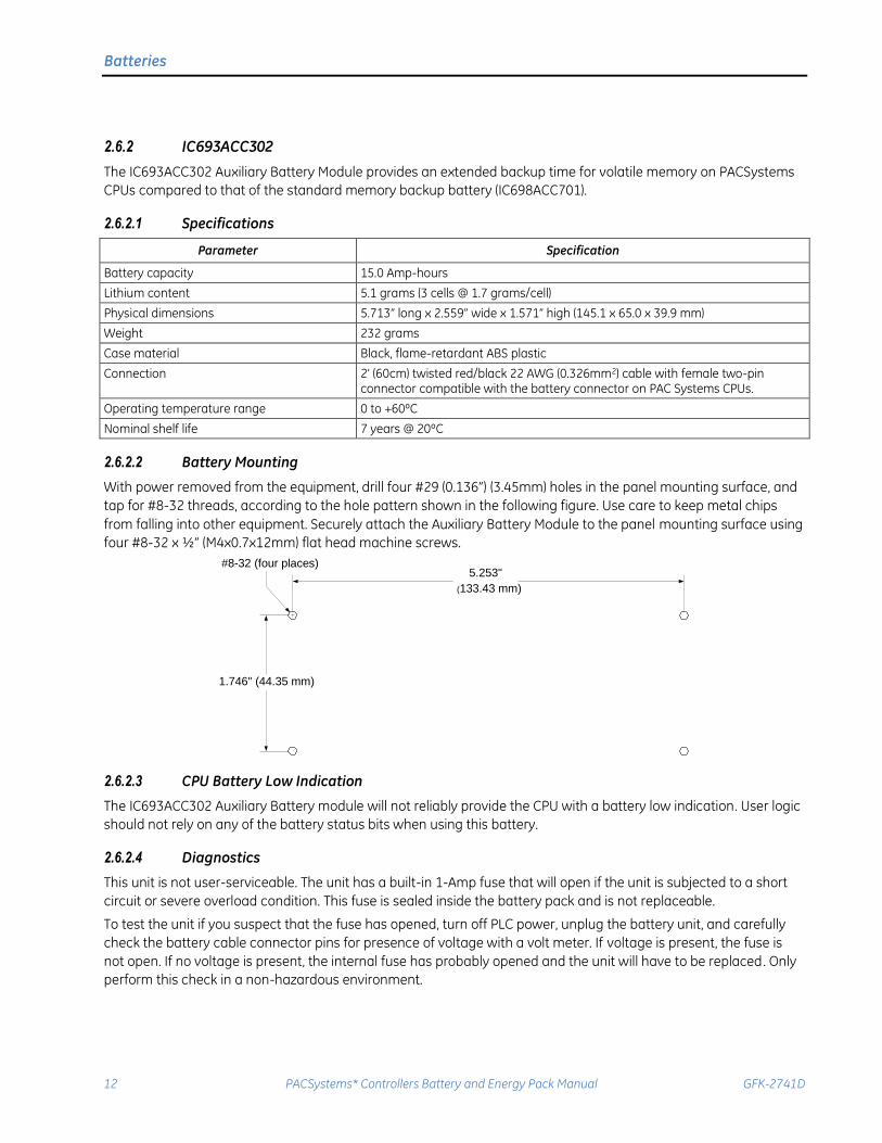
2.6.2 IC693ACC302
The IC693ACC302 Auxiliary Battery Module provides an extended backup time for volatile memory on PACSystems
CPUs compared to that of the standard memory backup battery (IC698ACC701).
2.6.2.1 Specifications
Parameter Specification
Battery capacity 15.0 Amp-hours
Lithium content 5.1 grams (3 cells @ 1.7 grams/cell)
Physical dimensions 5.713” long x 2.559” wide x 1.571” high (145.1 x 65.0 x 39.9 mm)
Weight 232 grams
Case material Black, flame-retardant ABS plastic
Connection 2’ (60cm) twisted red/black 22 AWG (0.326mm2) cable with female two-pin connector compatible with the battery connector on PAC Systems CPUs.
Operating temperature range 0 to +60ºC
Nominal shelf life 7 years @ 20ºC
2.6.2.2 Battery Mounting
With power removed from the equipment, drill four #29 (0.136”) (3.45mm) holes in the panel mounting surface, and
tap for #8-32 threads, according to the hole pattern shown in the following figure. Use care to keep metal chips
from falling into other equipment. Securely attach the Auxiliary Battery Module to the panel mounting surface using
four #8-32 x ½” (M4x0.7x12mm) flat head machine screws.
5.253"
(133.43 mm)
1.746" (44.35 mm)
#8-32 (four places)
2.6.2.3 CPU Battery Low Indication
The IC693ACC302 Auxiliary Battery module will not reliably provide the CPU with a battery low indication. User logic
should not rely on any of the battery status bits when using this battery.
2.6.2.4 Diagnostics
This unit is not user-serviceable. The unit has a built-in 1-Amp fuse that will open if the unit is subjected to a short
circuit or severe overload condition. This fuse is sealed inside the battery pack and is not replaceable.
To test the unit if you suspect that the fuse has opened, turn off PLC power, unplug the battery unit, and carefully
check the battery cable connector pins for presence of voltage with a volt meter. If voltage is present, the fuse is
not open. If no voltage is present, the internal fuse has probably opened and the unit will have to be replaced. Only
perform this check in a non-hazardous environment.
Batteries
GFK-2741D June 2015 13
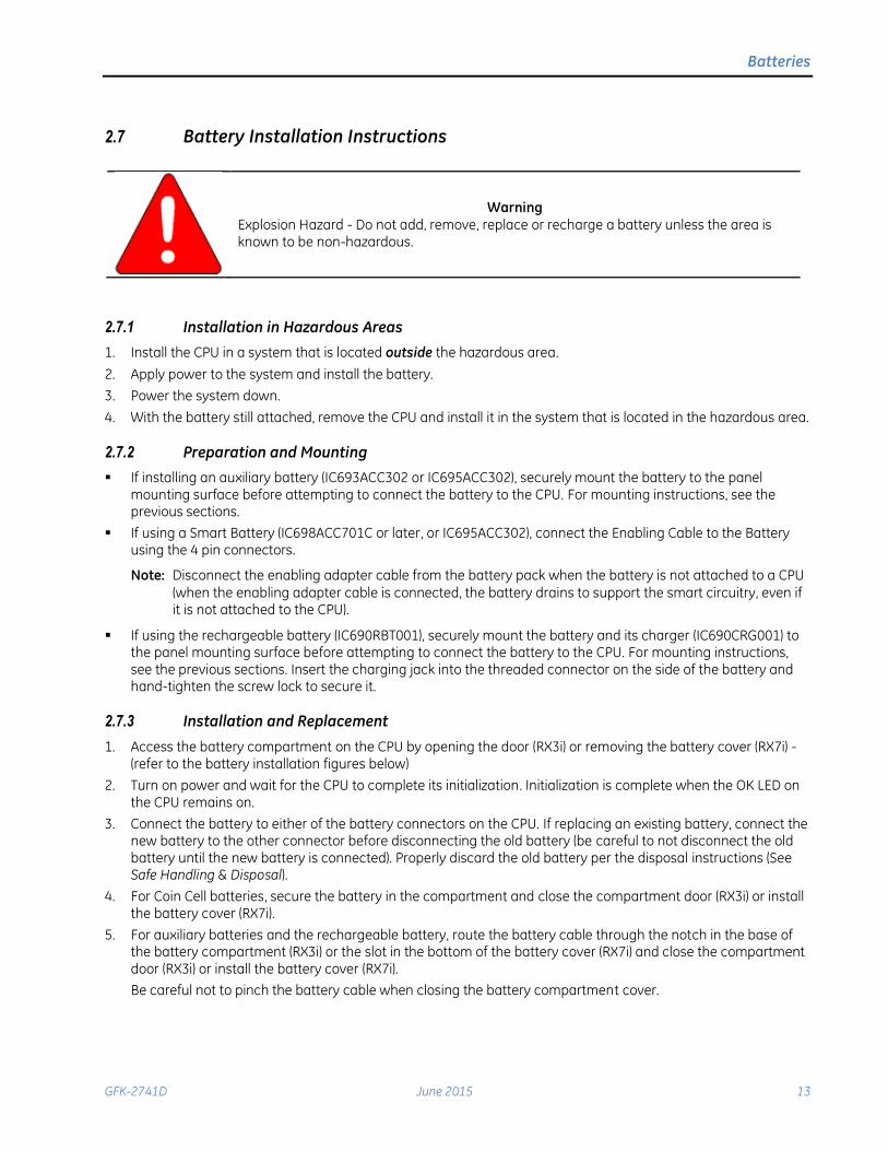
2.7 Battery Installation Instructions
Warning Explosion Hazard - Do not add, remove, replace or recharge a battery unless the area is known to be non-hazardous.
2.7.1 Installation in Hazardous Areas
1. Install the CPU in a system that is located outside the hazardous area.
2. Apply power to the system and install the battery.
3. Power the system down.
4. With the battery still attached, remove the CPU and install it in the system that is located in the hazardous area.
2.7.2 Preparation and Mounting
If installing an auxiliary battery (IC693ACC302 or IC695ACC302), securely mount the battery to the panel mounting surface before attempting to connect the battery to the CPU. For mounting instructions, see the previous sections.
If using a Smart Battery (IC698ACC701C or later, or IC695ACC302), connect the Enabling Cable to the Battery using the 4 pin connectors.
Note: Disconnect the enabling adapter cable from the battery pack when the battery is not attached to a CPU
(when the enabling adapter cable is connected, the battery drains to support the smart circuitry, even if it is not attached to the CPU).
If using the rechargeable battery (IC690RBT001), securely mount the battery and its charger (IC690CRG001) to the panel mounting surface before attempting to connect the battery to the CPU. For mounting instructions, see the previous sections. Insert the charging jack into the threaded connector on the side of the battery and hand-tighten the screw lock to secure it.
2.7.3 Installation and Replacement
1. Access the battery compartment on the CPU by opening the door (RX3i) or removing the battery cover (RX7i) - (refer to the battery installation figures below)
2. Turn on power and wait for the CPU to complete its initialization. Initialization is complete when the OK LED on the CPU remains on.
3. Connect the battery to either of the battery connectors on the CPU. If replacing an existing battery, connect the new battery to the other connector before disconnecting the old battery (be careful to not disconnect the old battery until the new battery is connected). Properly discard the old battery per the disposal instructions (See Safe Handling & Disposal).
4. For Coin Cell batteries, secure the battery in the compartment and close the compartment door (RX3i) or install the battery cover (RX7i).
5. For auxiliary batteries and the rechargeable battery, route the battery cable through the notch in the base of the battery compartment (RX3i) or the slot in the bottom of the battery cover (RX7i) and close the compartment door (RX3i) or install the battery cover (RX7i).
Be careful not to pinch the battery cable when closing the battery compartment cover.

Batteries
14 PACSystems* Controllers Battery and Energy Pack Manual GFK-2741D
RX3i Battery Installation Diagram RX7i Battery Installation Diagram
1.
Notch at base of battery compartment
Connectors
2.An earlier version RX7i CPU may not have a slot in its battery door. For these CPUs, replace the door (supplied with the IC698ACC701 replacement battery).
Connectors
Battery Compartment
Notch in Battery Cover
Battery
Compartment

Batteries
GFK-2741D June 2015 15
2.8 Date Code & Shelf Life
Date Code:
The date code is located on the product label on the front of the battery. The date code consists of four digits, such
as 1234. The first two digits represent the year of manufacture in the 21st century; such as 12 for 2012. The last two
digits indicate the fiscal week of manufacture; for example 34 stands for fiscal week 34.
Shelf Life:
Unused battery packs that have exceeded their shelf life should not be used and should be discarded according to
Safe Handling & Disposal instructions below.
Battery Catalog# Shelf-Life
Smart Auxiliary IC695ACC302 7 years @ 20°C without the enabling adapter cable attached
Legacy Coin Cell IC698ACC701 A & B 5 years @ 20°C
Smart Coin Cell IC698ACC701 C and later 5 years @ 20°C without the enabling adapter cable attached
Legacy Auxiliary IC693ACC302 7 years @ 20°C
Rechargeable IC690RBT001 3 years @ 20°C
2.9 Safe Handling & Disposal
Warning
Batteries may present a risk of fire, explosion, or chemical burn if mistreated. Do not crush, disassemble, short-circuit, or dispose of in fire. Use of batteries not specified for use with PACSystems products may present a risk of fire or explosion. Refer to Section 2.2 for details on PACSystems battery compatibility.
Lithium Battery Warning
Do not recharge, disassemble, heat or incinerate lithium batteries. Dispose of lithium batteries in accordance with federal, state, and local regulations. Be sure to consult with the appropriate regulatory agencies before disposing of batteries.
Batteries
16 PACSystems* Controllers Battery and Energy Pack Manual GFK-2741D
2.10 Agency Certifications
In order to maintain agency certification batteries must be mounted within a protective enclosure providing a
pollution degree 2 environment, IP54 ingress protection, and mechanical impact strength equal to or greater than
3.5 Joules.
Note: Batteries that mount within the housing of a module only need to adhere to the installation requirements of
that module.
2.10.1 Batteries
These products are UL Listed Accessories for the PACSystems RX3i and RX7i family of PLCs and have been
evaluated to the following standards for use in ordinary and hazardous areas:
UL 2054
ANSI/ISA 12.12.0.1 (UL File E157515)
In addition, IC690RBT001 has been evaluated to IEC62133
2.10.2 Charger: IC690CRG001
This product is a UL Recognized Component and has been evaluated to the following standard for use in ordinary
location:
UL 60601-1 (UL file E208921)
Note: Charger has not been evaluated for use in hazardous areas and therefore should not be used in that environment.
Energy Packs
GFK-2741D June 2015 17
3. Energy Packs
An Energy Pack is used in conjunction with a Controller to preserve user memory in the Controller during power
fluctuations or outages.
If system power is lost, the Energy Pack maintains power long enough for a Controller to write its user memory
contents to non-volatile memory. When system power is restored, the user memory is restored if the Controller is
configured to power up from RAM.
3.1 Energy Pack Compatibility
The correct Energy Pack must be used with the corresponding controller. Do not attempt combinations except those shown as “compatible” in the table below:
Energy Pack
Cap Pack
Controller
IC695ACC400
IC695ACC400
IC695ACC402
IC695ACC412
ICRXIACCEPK01A
ICRXIACCCPK01A
ICRXICTL000 Incompatible Incompatible Compatible
IC695CPE305 IC695CPE310
Compatible Incompatible Incompatible
IC695CPE330 Incompatible Compatible Incompatible
3.2 PACSystems RXi Energy Pack (ICRXIACCEPK01A)
3.2.1 Specifications
Part Numbers
ICRXIACCEPK01A Energy Pack. Includes base, Cap Pack module and Energy Pack to Controller cable
ICRXIACCCPK01A Replacement Cap Pack module
ICRXIACCCBL01A Replacement 0.3m (12”) Energy Pack to Controller cable
Functional Specifications
Dimensions 114.05 × 77.47 × 63.75 mm (4.49” × 3.05” × 2.51”)
Input voltage range 20–30 Vdc
Input power, maximum 36 W + connected device power requirement
Output voltage range 18–30Vdc
Output power maximum 45 W
Output current maximum 2.25 A
Backup trip voltage 19 Vdc ±4%
Capacitor Pack life expectancy 5 years
Environmental Specifications
The Energy Pack shall be installed in a location that is not exposed to corrosive gases or liquids, rain, or direct
sunlight, and that meets the environmental specifications listed below.
Operating Temperature, surrounding air -25˚C to 60˚C
Storage Temperature -40C to +85C (-40°F to 185°F)
Humidity 5% to 95%, non-condensing
Environment Restricted Access Area and Pollution Degree 2 environment as defined below.
Energy Packs
18 PACSystems* Controllers Battery and Energy Pack Manual GFK-2741D
3.2.2 General Installation Environments
In order to maintain the Agency Certifications listed below, installation must comply with the following
requirements.
Warning
The Energy Pack must be installed in a Restricted Access Area, as defined by:
Access can only be gained by service persons or by users who have been instructed
about the reasons for the restrictions applied to the location and about any
precautions that shall be taken; and
Access is through the use of a tool or lock and key, or other means of security, and
is controlled by the authority responsible for the location.
The Energy Pack must be installed in a Pollution Degree 2 environment as defined by:
Pollution Degree 2 applies where there is only non-conductive pollution that might temporarily become
conductive due to occasional condensation.
3.2.3 Industrial Environment Installations
For use in industrial environments this product is considered open equipment [having live electrical parts that may
be accessible to users] and must be installed in an ultimate enclosure that is manufactured to provide safety. At a
minimum, the enclosure shall provide a degree of protection against solid objects up to 12mm (0.5”) (e.g. fingers).
This equates to a NEMA/UL Type 1 enclosure or an IP20 rating (IEC60529) providing at least a pollution degree 2
environment.
3.2.4 Hardware Installation
The Energy Pack can be mounted on a standard EN50022 DIN rail or an equipment panel. It is designed to be
mounted adjacent to the Controller and connected to the Controller using the provided 12” (0.3m) cable
(ICRXIACCCBL01A) or a user-supplied cable.
Refer to section on Grounding for important grounding instructions.
3.2.4.1 Mounting the Energy Pack on a DIN Rail
The Energy Pack snaps easily onto the DIN rail. No tools are required.
Note: To remove the Energy Pack from the DIN rail, use a small flat-blade screwdriver to pull down on the tab on
the bottom of the Energy Pack and then lift the module off the DIN rail.
Energy Packs
GFK-2741D June 2015 19
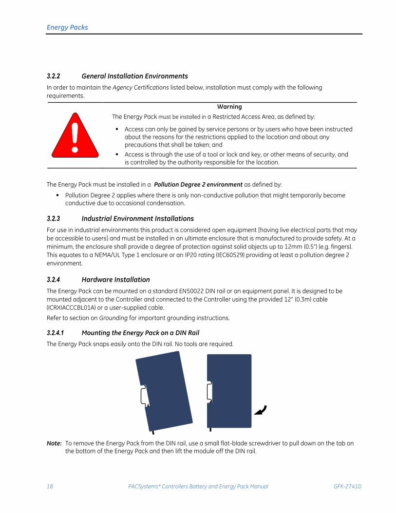
3.2.4.2 Mounting the Energy Pack Directly on a Panel
Caution Over tightening the mounting screws could crack the plastic housing.
Heat dissipation: When mounting the Energy Pack on a panel, allow a minimum clearance of 25.4mm (1”) on the
four sides of the unit (right, left, top and the bottom).
Recommended fasteners: Four M4-0.7 machine screws with minimum length of 25mm (or 8-32, 1” min. length) and
nuts.
1. Drill four mounting holes using the spacing shown in the following drawing.
2. Use the machine screws and nuts to attach the Energy Pack to the panel.
2.610"
66.294mm
4.0
70"
10
3.3
78m
m
0.188"
4.763mm
Drilling Pattern for Direct Panel Mounting
Energy Packs
20 PACSystems* Controllers Battery and Energy Pack Manual GFK-2741D
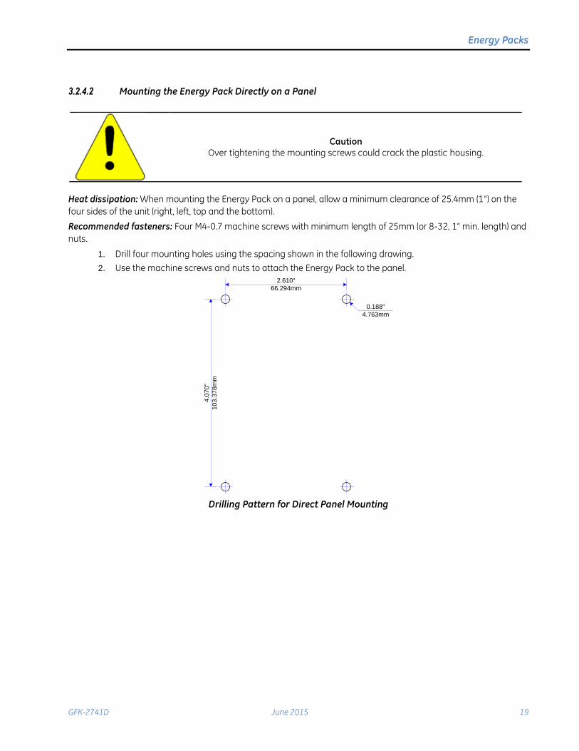
3.2.5 Cable Connections
Output Power and
Control
Input Power
User-supplied
input power cable
ICRXIACCCBL01A
Cable (supplied) or
user-supplied cable
Input Power and Output Power/Control Connections
3.2.5.1 Connecting Input Power to the Energy Pack
You will need:
A power cord with 18 AWG (0.82mm2) copper wires
An 18 AWG (0.82mm2) copper wire for frame ground
An input power terminal block – provided (Weidmüller part number 1748010000)
A small flat-head screwdriver (such as a 1.4 mm jeweler’s screwdriver)
A 24Vdc, 72 W minimum power supply, that must provide reliable grounding and Secondary Extra Low
Voltage (SELV) output or other form of isolating secondary circuit.
Power Supply Requirements: When the Energy Pack is powered by an LPS Class 2, or a Limited
Voltage/Current power source, no additional over-current protection is required. Otherwise, power supply
branch circuit overcurrent protection of no more than 20 A with a readily accessible disconnect is required,
along with supplementary protection ranging from 4 to 7 amps on the output of the power supply.
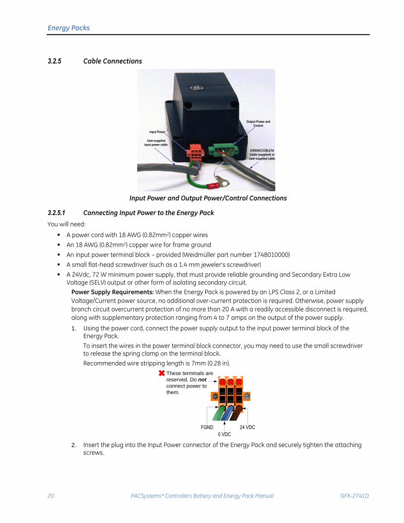
1. Using the power cord, connect the power supply output to the input power terminal block of theEnergy Pack.
To insert the wires in the power terminal block connector, you may need to use the small screwdriverto release the spring clamp on the terminal block.
Recommended wire stripping length is 7mm (0.28 in).
FGND
0 VDC
24 VDC
These terminals are
reserved. Do not
connect power to
them.
2. Insert the plug into the Input Power connector of the Energy Pack and securely tighten the attachingscrews.
Energy Packs
GFK-2741D June 2015 21
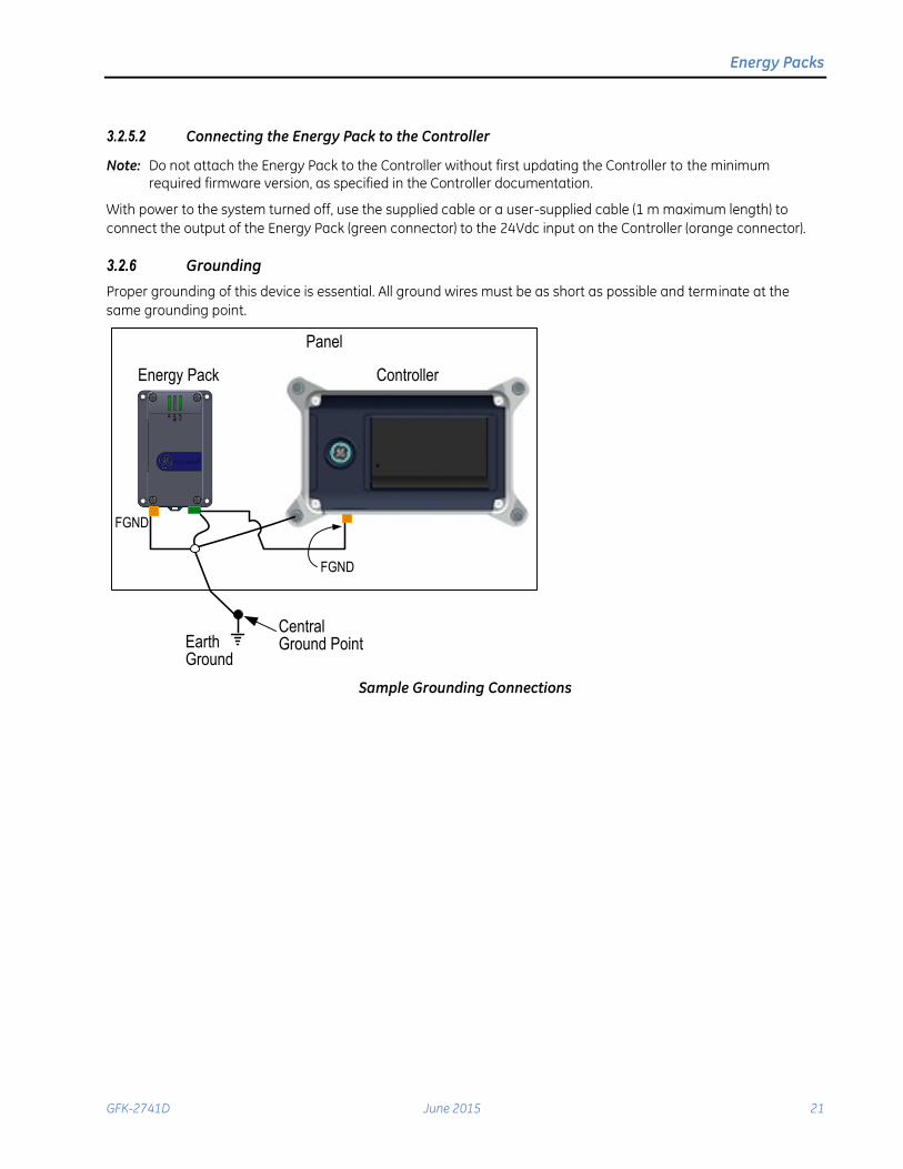
3.2.5.2 Connecting the Energy Pack to the Controller
Note: Do not attach the Energy Pack to the Controller without first updating the Controller to the minimum
required firmware version, as specified in the Controller documentation.
With power to the system turned off, use the supplied cable or a user-supplied cable (1 m maximum length) to
connect the output of the Energy Pack (green connector) to the 24Vdc input on the Controller (orange connector).
3.2.6 Grounding
Proper grounding of this device is essential. All ground wires must be as short as possible and terminate at the
same grounding point.
Earth Ground
Central Ground Point
FGND
Energy Pack Controller
Panel
FGND
Sample Grounding Connections
Energy Packs
22 PACSystems* Controllers Battery and Energy Pack Manual GFK-2741D
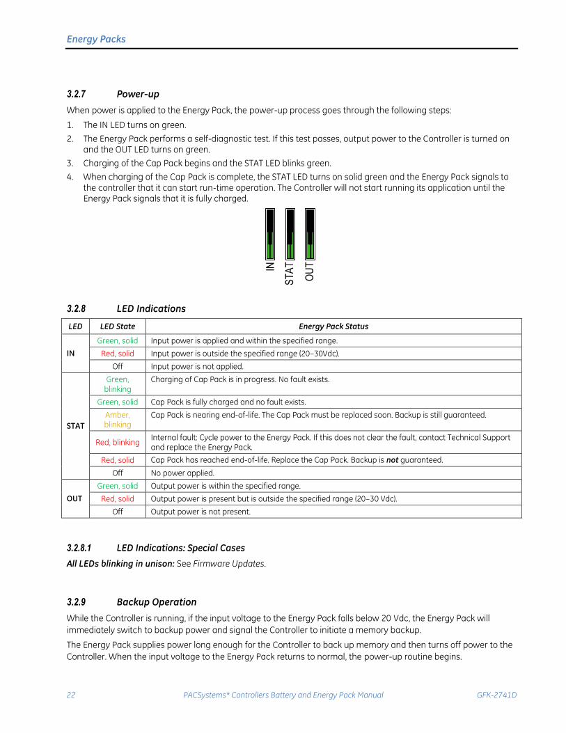
3.2.7 Power-up
When power is applied to the Energy Pack, the power-up process goes through the following steps:
1. The IN LED turns on green.
2. The Energy Pack performs a self-diagnostic test. If this test passes, output power to the Controller is turned onand the OUT LED turns on green.
3. Charging of the Cap Pack begins and the STAT LED blinks green.
4. When charging of the Cap Pack is complete, the STAT LED turns on solid green and the Energy Pack signals tothe controller that it can start run-time operation. The Controller will not start running its application until theEnergy Pack signals that it is fully charged.
IN
ST
AT
OU
T3.2.8 LED Indications
LED LED State Energy Pack Status
IN
Green, solid Input power is applied and within the specified range.
Red, solid Input power is outside the specified range (20–30Vdc).
Off Input power is not applied.
STAT
Green, blinking
Charging of Cap Pack is in progress. No fault exists.
Green, solid Cap Pack is fully charged and no fault exists.
Amber, blinking
Cap Pack is nearing end-of-life. The Cap Pack must be replaced soon. Backup is still guaranteed.
Red, blinking Internal fault: Cycle power to the Energy Pack. If this does not clear the fault, contact Technical Support and replace the Energy Pack.
Red, solid Cap Pack has reached end-of-life. Replace the Cap Pack. Backup is not guaranteed.
Off No power applied.
OUT
Green, solid Output power is within the specified range.
Red, solid Output power is present but is outside the specified range (20–30 Vdc).
Off Output power is not present.
3.2.8.1 LED Indications: Special Cases
All LEDs blinking in unison: See Firmware Updates.
3.2.9 Backup Operation
While the Controller is running, if the input voltage to the Energy Pack falls below 20 Vdc, the Energy Pack will
immediately switch to backup power and signal the Controller to initiate a memory backup.
The Energy Pack supplies power long enough for the Controller to back up memory and then turns off power to the
Controller. When the input voltage to the Energy Pack returns to normal, the power-up routine begins.
Energy Packs
GFK-2741D June 2015 23
3.2.10 Service and Maintenance
3.2.10.1 Replacing the Cap Pack Module
The Cap Pack is typically removed and replaced while power is applied to the Energy Pack (hot swapped.)
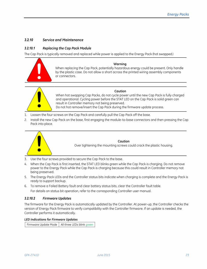
Warning When replacing the Cap Pack, potentially hazardous energy could be present. Only handle by the plastic case. Do not allow a short across the printed wiring assembly components or connectors.
Caution
When hot swapping Cap Packs, do not cycle power until the new Cap Pack is fully charged and operational. Cycling power before the STAT LED on the Cap Pack is solid green can result in Controller memory not being preserved. Do not hot remove/insert the Cap Pack during the firmware update process.
1. Loosen the four screws on the Cap Pack and carefully pull the Cap Pack off the base.
2. Install the new Cap Pack on the base, first engaging the module-to-base connectors and then pressing the CapPack into place.
Caution
Over tightening the mounting screws could crack the plastic housing.
3. Use the four screws provided to secure the Cap Pack to the base.
4. When the Cap Pack is first inserted, the STAT LED blinks green while the Cap Pack is charging. Do not removepower to the Energy Pack while the Cap Pack is charging because this could result in Controller memory notbeing preserved.
5. The Energy Pack LEDs and the Controller status bits indicate when charging is complete and the Energy Pack isready to support backup.
6. To remove a Failed Battery fault and clear battery status bits, clear the Controller fault table.
For details on status bit operation, refer to the corresponding Controller user manual.
3.2.10.2 Firmware Updates
The firmware for the Energy Pack is automatically updated by the Controller. At power-up, the Controller checks the
version of Energy Pack firmware to verify compatibility with the Controller firmware. If an update is needed, the
Controller performs it automatically.
LED Indications for Firmware Updates
Firmware Update Mode All three LEDs blink green
Energy Packs
24 PACSystems* Controllers Battery and Energy Pack Manual GFK-2741D
3.2.11 Diagnostics
3.2.11.1 System Version Information
The Controller’s web-based home page displays serial number and version information for the Base and Cap Pack.
For additional information, refer to the Controller user manual.
3.2.11.2 Status Information
The Energy Pack provides the following status information to the Controller, which it uses to generate fault and
status bit indications. For Controller fault and status bit details, refer to the Controller user manual.
Charging The Energy Pack is charging; not yet fully charged.
Fault A hardware fault exists in the Energy Pack.
Low capacitance The Energy Pack is near its end of life and should be replaced.
Charged The Energy Pack is fully charged and is ready to support CPU operation.
3.2.11.3 Energy Pack LEDs
Details on the LED operation for this Energy Pack are listed in LED Indications.
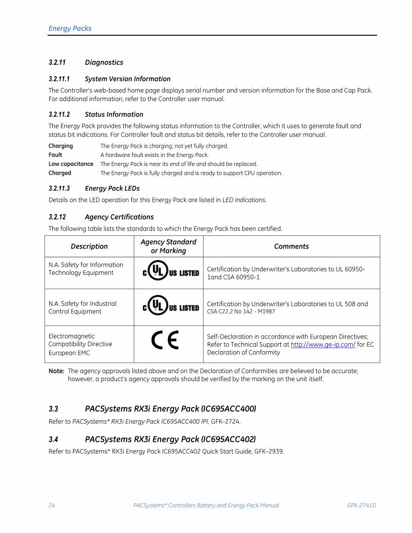
3.2.12 Agency Certifications
The following table lists the standards to which the Energy Pack has been certified.
Description Agency Standard
or Marking Comments
N.A. Safety for Information Technology Equipment
Certification by Underwriter's Laboratories to UL 60950-1and CSA 60950-1
N.A. Safety for Industrial Control Equipment
Certification by Underwriter's Laboratories to UL 508 and CSA C22.2 No 142 - M1987
Electromagnetic Compatibility Directive
European EMC
Self-Declaration in accordance with European Directives; Refer to Technical Support at http://www.ge-ip.com/ for EC Declaration of Conformity
Note: The agency approvals listed above and on the Declaration of Conformities are believed to be accurate; however, a product’s agency approvals should be verified by the marking on the unit itself.
3.3 PACSystems RX3i Energy Pack (IC695ACC400)
Refer to PACSystems* RX3i Energy Pack IC695ACC400 IPI, GFK-2724.
3.4 PACSystems RX3i Energy Pack (IC695ACC402)
Refer to PACSystems* RX3i Energy Pack IC695ACC402 Quick Start Guide, GFK-2939.
Related Documents
GFK-2741D June 2015 25
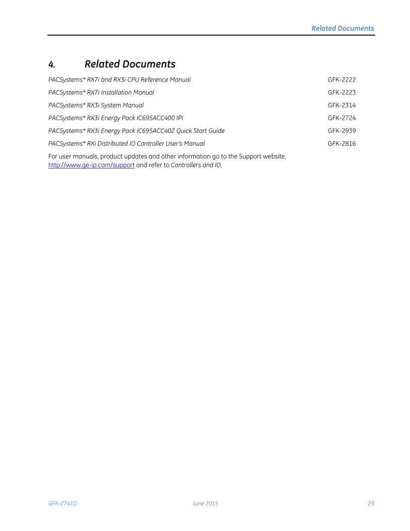
4. Related Documents
PACSystems* RX7i and RX3i CPU Reference Manual GFK-2222
PACSystems* RX7i Installation Manual GFK-2223
PACSystems* RX3i System Manual GFK-2314
PACSystems* RX3i Energy Pack IC695ACC400 IPI GFK-2724
PACSystems* RX3i Energy Pack IC695ACC402 Quick Start Guide GFK-2939
PACSystems* RXi Distributed IO Controller User's Manual GFK-2816
For user manuals, product updates and other information go to the Support website,
http://www.ge-ip.com/support and refer to Controllers and IO.

26
GE Intelligent Platforms Information Centers
Headquarters: 1-800-433-2682 or 1-434-978-5100
Global regional phone numbers are available on our web site www.ge-ip.com
Additional Resources
For more information, please visit the GE Intelligent Platforms web site:
www.ge-ip.com
©2013-2015 GE Intelligent Platforms, Inc. All Rights Reserved
*Trademark of GE Intelligent Platforms, Inc.
All other brands or names are property of their respective holders. GFK-2741D