Embed Size (px)
Citation preview

Page 1 of 11
Page 2 of 11
Page 3 of 11
Annexure ’A’
Amendment No. 1 to Specification No. RDSO/SPN/TC/61/2007 (Rev. 2) for Integrated Passenger Information System.
1.0 An additional Clause No. 3.2.16 shall be added as below:
Clause 3.2.16: Hardware & software of various types of display boards including main & platform data communication hubs shall be designed in such a way that, the database consisting of train information must be uploaded to display boards and communication hubs within 60 seconds from Central Console Unit (CCU). 60 seconds upload time is for a typical system consisting of one MDCH which is driving two multiline display boards and one at a glance display board, any number of PDCHs connected to MDCH and each PDCH driving three platform display boards and one at a glance display board. The train information uploaded typically would be of ten trains’ data for multiline display board, three trains’ data for platform display board and one train data for at a glance display board. In case of coach guidance display boards, train information of all the coaches in a platform should be uploaded within 60 seconds, as it is a separate operation. The upload time may proportionally increase in case of larger set up dealing with more numbers of trains.
2.0 The existing Clause No. 3.3.9 shall be substituted as given below: Clause 3.3.9:The display of the fixed titles viz. train number, name, expected time,
arrival/ departure, platform number etc. should be screen printed in capital letters with the white back ground and shall be clearly readable from a distance of minimum 50 meters in the brightest part of the day. Color of characters should be preferably in “blue” or otherwise specified by purchaser.
3.0 The existing Clause No. 3.3.16 shall be substituted as given below: Clause 3.3.16: Every display board shall be covered with U.V. stabilized polycarbonate
sheet with thickness of minimum 3mm in order to give good visibility and protection against dust. Single polycarbonate sheet without any joint should cover the complete board in case of single line display board, coach guidance display board, at a glance display board with coach guidance display board and upto two lines in case of multi line display board. Multi line display boards with more than two lines can have either a single polycarbonate sheet for complete board or individual single polycarbonate sheet for individual line or as specified by purchaser.
4.0 The existing Clause No. 3.3.35 shall be substituted as given below:
Clause 3.3.35: Preferably 5 pair (5 core for working and 5 core for standby) color coded
& PVC insulated twin twisted Data Communication Cable in which each core is made up of size 7/0.20 (7 strands & each strand of 0.20mm diameter) & having insulation thickness of 0.25mm, polyester taped, 0.6 mm Drain Wire, overlapped with Aluminum Foil for screening, polyester taped and with outer sheath thickness
Page 4 of 11
of 1.3mm shall be provided for the data communication wherever required. Tolerance in dimensions should be within ± 10%.
5.0 An additional Clause 3.4.11 shall be added below:
Clause 3.4.11: The mounting of LEDs on all types of display boards should be such that
it should have more horizontal viewing angle.
6.0 An additional Clause 3.4.12 is added as under:
Clause 3.4.12: Nylon based protective grid in black colour shall be provided for LEDs to avoid bending in order to have uniform intensity of the display boards.
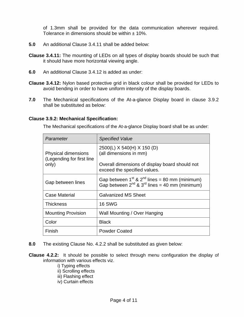
7.0 The Mechanical specifications of the At-a-glance Display board in clause 3.9.2
shall be substituted as below: Clause 3.9.2: Mechanical Specification:
The Mechanical specifications of the At-a-glance Display board shall be as under:
Parameter Specified Value
Physical dimensions (Legending for first line only)
2500(L) X 540(H) X 150 (D) (all dimensions in mm) Overall dimensions of display board should not exceed the specified values.
Gap between lines Gap between 1st & 2nd lines = 80 mm (minimum) Gap between 2nd & 3rd lines = 40 mm (minimum)
Case Material Galvanized MS Sheet
Thickness 16 SWG
Mounting Provision Wall Mounting / Over Hanging
Color Black
Finish Powder Coated
8.0 The existing Clause No. 4.2.2 shall be substituted as given below:
Clause 4.2.2: It should be possible to select through menu configuration the display of information with various effects viz.
i) Typing effects ii) Scrolling effects iii) Flashing effect iv) Curtain effects

Page 5 of 11
9.0 The existing Clause No. 5.1 shall be substituted as given below: Clause 5.1: Power supply units of all types of display boards and communication hubs
shall be operated from AC source ranging from 160 to 270 Volts (with tolerance of +/-10 V), 50 Hz AC, single phase with over voltage, under voltage and short circuit protection.
10.0 The existing Clause No. 5.2 shall be substituted as given below:
Clause 5.2: All the power supply units shall be operated at 50% load of maximum working capacity. Power supply units shall be SMPS type of standard make.
11.0 The existing Clause No. 5.5 shall be substituted as given below:
Clause 5.5: PVC insulated flexible 3 core power cables provided for display boards shall
conform to specification no. IS: 694:1990 reaffirmed 1995 or latest and shall have sufficient cross sectional area of 2.5 sq mm copper conductor.
12.0 The existing Clause No. 7.2 & 7.2.1 shall be substituted as given below:
Clause 7.2: Insulation Resistance Test: - This test shall be carried out –
(a) Before the high voltage test (b) After the high voltage test (c) After completion of the climatic test
There shall be no appreciable change (value more than 10 Mega ohms and variation within 10%) in the values measured before and after high voltage test. After the completion of climatic test, the values shall not be less than 10 Mega ohms for the equipment at a temperature of 400 C and relative humidity 60%. The measurement shall be made at a potential of 500V DC.
13.0 The existing Clause No. 7.3 & 7.3.1 shall be substituted as given below:
Clause 7.3: Applied High Voltage Test: - The equipment shall withstand for one minute
without puncture and arcing, a test voltage applied between line terminal and earth as mentioned below:
(a) AC line terminals and earth, test voltage of 1500V AC (b) DC line terminals and earth, test voltage of 500V AC
The test voltage shall be alternating of approximately sinusoidal waveform of any frequency between 50 Hz and 100 Hz. Printed circuit cards shall be removed during the test.
14.0 The existing Clause No. 7.4 & 7.4.1 shall be substituted as given below:

Page 6 of 11
Clause 7.4: Environmental/ Climate Tests:-
7.4.1 The various types of display boards, MDCH and PDCH shall be capable of working in non-air conditioned environment in the field.
7.4.2 The display systems shall be suitable for installation on AC/ DC electrified and
non-electrified sections. It shall be suitable in all sections including where locomotives having thyristor controlled single phase or 3-phase induction motors haul passenger or freight trains and where chopper controlled EMU stocks are operated.
7.4.3 The various types of display systems shall meet the following climatic and
environmental requirements: SN TEST REFERENCE
Change of temp test Low temp –10oC ± 3oC High temp +70oC ± 2oC Rate of change in temperature
1oC / min
Duration 3 hrs at each temp. –10oC & +70oC Cycle 3
1.
Condition Fully functional during test
IS 9000 Part XIV Sect. II
Dry heat test Temp +70oC ± 2oC Duration 16 hrs
2.
Condition Fully functional during test
IEC-571; IS:9000 Part-III Sect 3
Cold test Temp –10oC ±3oC Duration 2 hours
3
Condition Fully functional during test.
IS 9000 Part II Sect. III
Damp heat test (Cyclic) Upper temp 40oC ±2oC Humidity 95% (+1%, -5%) Cycles 6
4.
Condition Fully functional during one hour period towards end of each cycle. Stabilization shall be done at 25o
±3oC
IS9000 Part V Sect. 2 Variant 1
Page 7 of 11
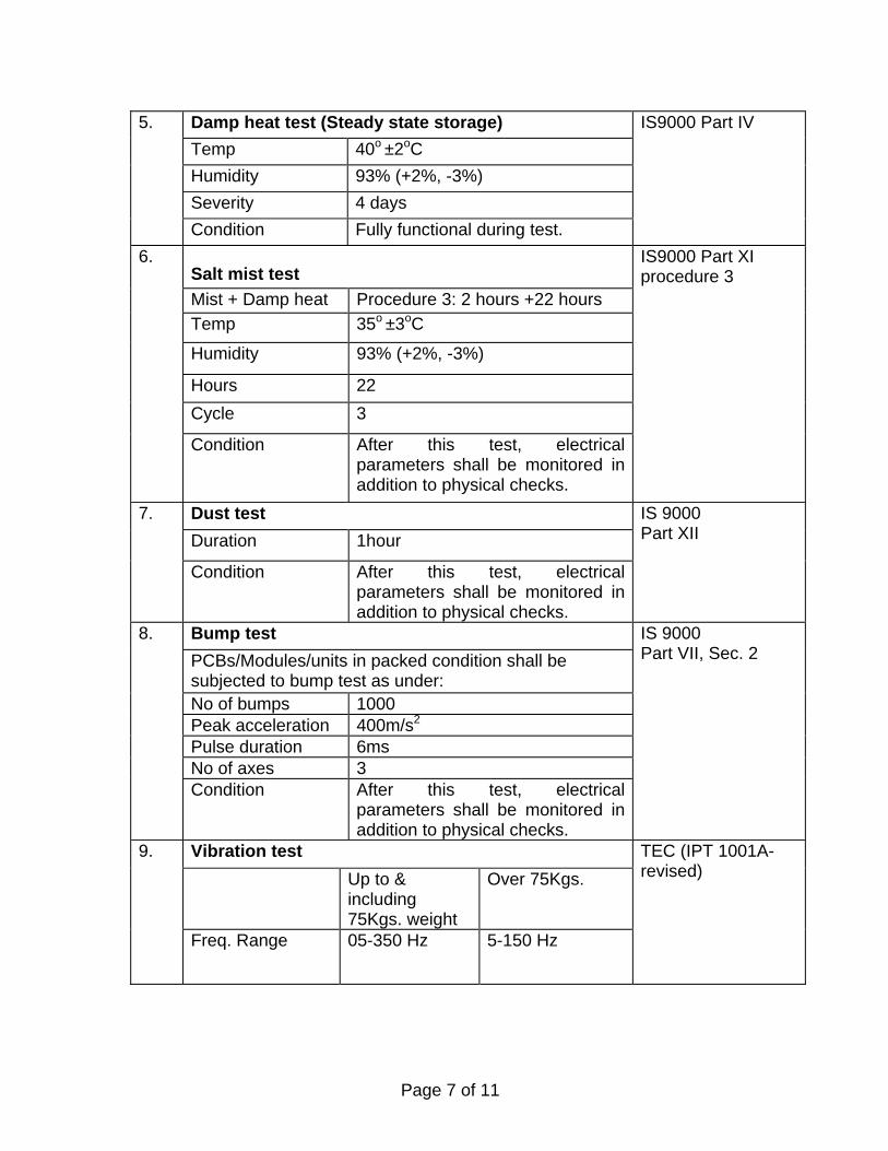
Damp heat test (Steady state storage) Temp 40o ±2oC Humidity 93% (+2%, -3%) Severity 4 days
5.
Condition Fully functional during test.
IS9000 Part IV
Salt mist test Mist + Damp heat Procedure 3: 2 hours +22 hours Temp 35o ±3oC
Humidity 93% (+2%, -3%)
Hours 22 Cycle 3
6.
Condition After this test, electrical parameters shall be monitored in addition to physical checks.
IS9000 Part XI procedure 3
Dust test Duration 1hour
7.
Condition After this test, electrical parameters shall be monitored in addition to physical checks.
IS 9000 Part XII
Bump test PCBs/Modules/units in packed condition shall be subjected to bump test as under: No of bumps 1000 Peak acceleration 400m/s2 Pulse duration 6ms No of axes 3
8.
Condition After this test, electrical parameters shall be monitored in addition to physical checks.
IS 9000 Part VII, Sec. 2
Vibration test Up to &
including 75Kgs. weight
Over 75Kgs. 9.
Freq. Range 05-350 Hz 5-150 Hz
TEC (IPT 1001A-revised)

Page 8 of 11
Amplitude ±6mm constant displacement or 15m/ sec.2
constant acceleration.
±6mm constant displacement or 15m/ sec.2
constant acceleration.
No. of axes 3 3 No of sweep cycle
20 10
Total duration 105min 105min If resonance is observed
10min at each resonant freq.
10min at each resonant freq.
Condition After this test, electrical parameters shall be monitored in addition to physical checks.
10. Production Testing: Environmental Stress Screening tests (ESS) for Printed Circuit Boards (PCB) & sub systems: (The manufacturer shall carry out the following ESS tests on all modules on 100% basis during production / testing in the sequence as follows. Suitable records shall be maintained regarding the compliance of these tests. )
10.1 Thermal cycling: The PCBs shall be subjected to thermal cycling as per the procedure given below. The assembled boards are to be subjected to rapid temperature cycling as mentioned below in the power off condition.
This temperature cycling from 0°C to 700C, ½ Hours at each temperature for 9 cycles and 1 hour at each temp. for the 10th cycle. Dwell time of 1 hour is provided for the last cycle in order to oxidize defective solder joints exposed through thermal stress.

Page 9 of 11
70°C, ½ Hour 1 Hour Ambient 0°C, ½ Hour
The rate of rise / fall of temp. shall be minimum 10°C per minute.
In addition to physical checks, the electrical parameters are also to be monitored after this test.
10.2 Power cycling: The power supply modules shall be subjected to 60 ON-OFF cycles for 1 hour. The ON-OFF switch usually provided in the modules may not be used for this purpose.
15.0 The existing Clause No. 7.5.1 shall be substituted as given below: Clause 7.5.1: The equipment shall comply with the requirements as specified in Clauses
3, 4 & 5. Compliance of Clause No. 3.3.24 is to be verified during type test only.
16.0 The existing Clause No. 11 shall be substituted as given below: Clause 11: INFORMATION TO BE SUPPLIED BY THE PURCHASER:-
The purchaser should clearly indicate details of required items including hardware and software which shall mainly consist of following items as per requirement.
S. No. Description of the Item Quantity
1 Control Console Unit consisting of standard PC with other accessories as per clause Nos. 3.2.1 to 3.2.14.
One Number
2 Announcement recordings in digital format as per details given by Railways One set
3 Software for announcement system, various types of display boards information management & CCTV management
One set with system and one set of soft copy in CD for each station.
4 Main Data Communication Hub and Platform Data Communication Hub. Firm has to supply these items depending upon requirement.
As per site requirement
5 Color of LEDs: Red or Orange or Green or Blue. As specified by the Customer

Page 10 of 11
S. No. Description of the Item Quantity
6 Multiline Display Boards of required lines (Single or Double sided and number of lines)
As per site requirement
7 Single Line Display Board (Single or double sided)
As per site requirement
8 Coach Guidance Display Boards As per site requirement
9 At-a-glance Display Boards with Coach Guidance System (Single sided)
As per site requirement
10 LCD/ Plasma TV as per Clause No.3.2.15 As per requirement
11 Five pair shielded communication Cable As per requirement
12 Power Cable and extension boards As per requirement
13 Any other items or features required by the purchaser
As per requirement
14 Suitable hardware & software for integration with Automatic Train Information System as per Clause No: 3.2.14 (Optional)
As per requirement
17.0 Diagram -3: APPLICATION SOFTWARE SCREEN SHOT (Clause No. 4.1.13) shall be substituted as given below:-
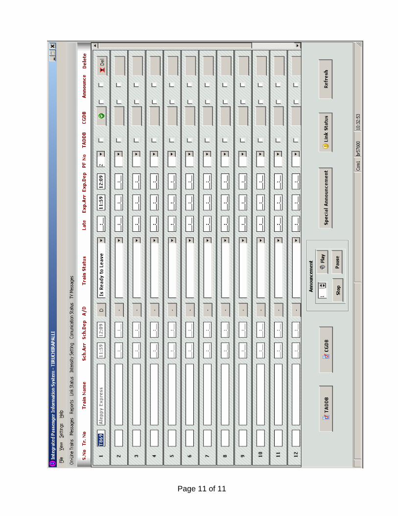
Page 11 of 11