Embed Size (px)
Citation preview
Page 1 of 56

Page 2 of 56
The Sea Marshall® brand derives its name from David Marshall the man who invented the concept of
the Personal Locator Beacon for commercial use back in the early 1970s. Marine Rescue
Technologies Ltd. today retains its founding roots as a thriving familly owned enterprise manufacturing
and selling the award winning Sea Marshall® Maritime Survivor Locating Devices into the following
markets, world-wide:
Commercial- General Purpose Marine
Commercial Marine and Commercial Fishing; the Sea Marshall® system has been adopted by
the Spanish and Belgian Fishing Fleets. The system is widely used around the world every day to
provide safety cover for mariners.
Renewable energy
Offshore windfarm operators are using the Sea Marshall® AU9-WF - SARfinder® man overboard
Alert & Locate system on a daily basis as part of the HSE requirement for safety when working on
offshore windfarms across Europe.
Yachting- General Purpsoe Marine
The Sea Marshall® MOB system is used by a number of the world’s superyachts and sport
sailors. The small compact AU9 PLB is popular with sailors and provides a highly effective safety
system for famillies and sports crews alike.
Oil & Gas
The ATEX (Intrinsically Safe) version of the Sea Marshall® system is used extensively throughout
the Oil & Gas industry worldwide for general man overboard cover and overside working.
ATEX ZONE 2 approved
Helicopter Transit
The Sea Marshall® AU9-HT high power personal locator beacon for use in passenger transit to
offshore installations.
ED-14F environmentally tested (part), CAA acceptance for flight.
Aquaculture
The Sea Marshall® Lone Worker man overboard Alert & Locate system is used extensively
across the world’s fishfarms; from the Faroe Islands through Ireland and Scotland to Australia to
provide safety cover for lone workers in the aquaculture industry.
Dive
Commercial and Leisure, a growing number of private divers and commercial dive boat operators
are using the Sea Marshall® lost diver locating system on a daily basis.The Sea Marshall®
system has been approved by the Egyptian authorities for carriage by dive boat operators.
Submariner
The pressure proof (300m) Sea Marshall® submarine PLB is in use with a growing number of the
world’s navies.

Page 3 of 56
Document description - AU9 Operators Guide Document number – 0106-09 Revision number – 011 Last updated – January 2011 Updated By – Andrew Brown
Pages CONTENTS - Description
4 Declaration Of Conformity
5 AU9 overview
6 Range distances
7 AU9 specifications
8 Different AU9 models
9 Using AU9 with receiver to create self managed SOS system
10 Arming AU9 – making ready for use
11 How to activate AU9
12 Switching AU9 OFF
13 – 14 Checking Au9 battery, Battery cahnge procedure
15 Checking the AU9 waterproofing seals – re-sealing the AU9
16 How often should I test my alerting unit
16 – 17 Wearing the AU9 (surface use)
18 – 22 Fitting AU9 into lifejacket, lifejacekt PLB fixing kit
23 Anti-tamper cap, AU9 maintenance
24 SUB-SEA AU9-D Diver version
25 – 26 AU9-D pressure cap fitting process
26 – 27 Re-sealing the AU9-D correctly
28 Using the AU9-D with pressure cap fitted
29 Initiating ‘SOS’ trasmission with pressure cap fitted
30 Using AU9-D with Surface Marker Bouy
31 AU9-D fitted to SMB – example photographs
32 Using AU9-D with boat mounted SARfinder locating unit
33 Wearing the AU9-D, Maintenance
34 – 35 500mW version of the AU9
36 Glossary of terms
37 - 53 HELICOPTER TRANSIT – OPERATOR GUIDE
54 Disclaimer notice
55 Warranty/Repairs/Disclaimer
56 NOTES

Page 4 of 56
Declaration of Conformity
Name of Manufacturer/Eu importer
Marine Rescue Technologies ltd. Units 3 & 4, Front Street Court, Middleton On The Wolds, East Yorkshire, YO25 9TZ United Kingdom [email protected] www.seamarshall.com
Declares that products: AU9-HT, AU9-X and AU9 series
Personal Locator Beacons
Conforms to the R&TTE Directive 1999/5/EC as attested by conformity
with the following harmonized standards:
EN 300 152-2 V1.1.1: Electromagnetic compatibility and Radio spectrum Matters
(ERM); Maritime Emergency Position Indicating Radio Beacons
(EPIRBs) intended for use on the frequency 121,5 MHz or the frequencies 121,5 MHz and 243 MHz for homing purposes only;
Part 2: Harmonized EN under article 3.2 of the R&TTE Directive.
(Article 3.2)
EN 300 152-3 V1.1.1: Electromagnetic compatibility and Radio
spectrum Matters (ERM); Maritime Emergency
Position Indicating Radio Beacons (EPIRBs)
intended for use on the frequency 121,5 MHz or
the frequencies 121,5 MHz and 243 MHz for
homing purposes only; Part 3: Harmonized EN
under article 3.3e of the R&TTE Directive.
(Article 3.3)
ETSI EN 301 489-22 V1.3.1:
Electromagnetic compatibility and Radio spectrum Matters
(ERM); ElectroMagnetic Compatibility (EMC) standard for radio
equipment and services; Part 22: Specific conditions for ground based VHF aeronautical mobile and fixed radio equipment.
(EMC)
Conform to the Low Voltage Directive 2006/95/EC as attested
by conformity with the following harmonized standard:
EN60950-1:2006: Information technology equipment — Safety — Part 1: General requirements.
Signed
Name David Marshall
Position Chairman
Date July 2010
FCC ID – YFGAU9
Figure 1 DOC

Page 5 of 56
1.0 AU9 OVERVIEW
The Sea Marshall® AU9, Alerting Unit series 9, has been designed to fullfill the requirement of the
Marine Industry for a long lasting, high quality, robust, high powered 121.5MHz locator beacon for
Man Overboard and Lost Diver Alert & Locate. The AU9 is derived from the well known PLB8 series of
Sea Marshall® personal locator beacon, it utilises the same format of operation so as to retain some
consistency of user familiarity and function in the field. In all other respects the AU9 unit is a
completely new and much more advanced/robust unit.
IMPORTANT – DO NOT TEMPER WITH THE WATERPIN SCREW (NO.3) ON THE TOP OF THE UNIT
Figure 2 AU9 overview

Page 6 of 56
1.1 The AU9 is available in two power ouptuts, 100mW. (The 500mW has approximately double the
tracking range of the 100mW version, NOTE some models are 500mW refer to figure 4 on page 8).
(NOTE – 100mW version of the AU9 has approximately half the tracking range of the 500mW unit)
Figure 3 Sea Marshall AU9 system range distances
NOTE – the tracking ranges listed are taken from tests where the receiver antenna has been correctly installed at the recommended
height with the AU9 correctly installed in either an SMB for divers or lifejacket, with antenna clip for normal use. The SMB gave the
maximum range listed as achieved during tests, the lifejacket AU9 installation gave the lower end of the ranges listed. Wearing the AU9
around the neck will reduce the tracking/alerting ranges to below the ranges listed here in.

Page 7 of 56
1.2 AU9 - SPECIFICATIONS
Frequency: 121.5 MHz
Bandwidth 25KHz (in alignmnet with ETSI)
Battery: user replaceable
Battery: 2 × AA lithium (either separate or a pack depeneding on 100mw or 500mW model)
Battery: 10 year full life (replace after 5 years or after use, which ever is sooner)
Endurance: Average 100mW = 42hours, 500mW = 24 hours
(60 months ‘approx’ on standby/armed)
Dimensions : 90mm high × 70mm wide(body) 80mm hinge/base cap × 35mm deep
Antenna length: Approx 50cm Helicopter model, Approx 90cm all other models
Modulation: Continuous swept tone A3X
Output power: 100mW or 500mmW depending on model
Temp range (storage): -55°C to + 70°C;
Approvals:
o CE o FCC ID YFGAU9
o ATEX – Zone 2 II 3G (AU9X only)
Test Units: 121.65MHz and 121.775MHz
Activation - Manual & Automatic with manual override (salt and fresh water) NOTE: some units have a fail-safe over ride function installed to allow the unit to auto-activate after 40 seconds
immersion in the event the unit has been switched off.
Waterproofing IP-68
AU9-D pressure proof to 70m depth when pressure cap is fitted
Antenna: 1m cable with flexible helical spring section, adaptable for lifejacket fitting
Strobe: inbuilt LED strobe on antenna flashes ‘SOS’.
ILS: internal loudspeaker 80dB
Weigth: 250gms (approx)
AU9-HT CAA flight approved
Environmental – the AU9 has passed the following environmental tests - Eurocae ED-14F
Temperature & altitude
Temperature variation
Humidity
Shock & crash safety
Explosive atmosphere
Waterproofness
Sand & Dust
Salt Fog
Magnetic Effect
RF – Susceptibility
Icing
ESD

Page 8 of 56
1.3 Different models of AU9
The Sea Marshall® AU9 units are colour coded with a coloured side switch/Model no. according to
market sector/operational type.
(images may differ in this booklet from actual products – manufacturer reserves the rigth to amend this booklet witout prior notice)
=
YYEELLLLOOWW (Model: AU9) = GGEENNEERRAALL PPUURRPPOOSSEE
5 second auto-activation (upon continuous immersion)
Manual activation
LED strobe on antenna
Automatic low battery warning indicator
100mW or 500mW power output versions available
=
GGRREEEENN (Model: AU9-WF) = RREENNEEWWAABBLLEE EENNEERRGGYY
2 second auto-activation (upon continuous immersion)
40 second fail safe auto-over ride
Manual activation
LED strobe on antenna
Automatic low battery warning indicator
500mW power output
=
BBLLAACCKK (Model: AU9X-Zone 2, AU9X-Zone 2 (HT) = OOIILL//GGAASS
5 second auto-activation (upon continuous immersion)
40 second fail safe auto-over ride
Manual activation
LED strobe on antenna
Automatic low battery warning indicator
100mW power output
=
RREEDD (Model : AU9-HT) = HHEELLIICCOOPPTTEERR TTRRAANNSSIITT
5 second auto-activation (upon continuous immersion)
40 second fail safe auto-over ride
Manual activation
LED strobe on antenna
Automatic low battery warning indicator
100mW power output
=
BBLLUUEE (Model : AU9-LW) = LLOONNEE WWOORRKKEERR//AAqquuaaccuullttuurree
2 second auto-activation (upon continuous immersion)
40 second fail safe auto-over ride
Manual activation
LED strobe on antenna
Automatic low battery warning indicator
100mW or 500mW power output versions available
=
PPUURRPPLLEE (Model : AU9-D) = DDIIVVEE
5 second auto-activation (upon continuous immersion)
Manual activation
LED strobe on antenna
Depth proof to 75m with pressure cap fitted
Automatic low battery warning indicator
100mW or 500mW power output versions available
Each unit is labelled to indicate the functions it is programmed with
Figure 4 AU9 descriptions

Page 9 of 56
1.4 USING THE AU9 WITH A RECEIVER TO CREATE A SELF MANAGED ‘SOS’ SYSTEM
Your AU9 will be used as part of a Sea Marshall® self managed Man Overboard Alert & Locate system known as a Maritime Survivor Locating Device. The advantage of the Sea Marshall® AU9 unit over other systems is that it transmits on the 121.5MHz international SAR homing frequency which means you can be tracked and rescued by the Coastguard of any country if outside assitance is required. Your AU9 can be used with any of the Sea Marshall® Base Unit receiver options to create a self managed SOS system:
1.4.1 ‘CREWGUARD’ GPS PLOT MOB ALARM – MOB monitor/alarm which automatically plots the GPS position of the vessel at the time the person fell overboard. The person in the water can be tracked on the international SAR homing frequency of 121.5MHz by Coast Guard SAR. A low cost safety solution providing essential cover for your crew/passengers.
1.4.2 UNMANNED AREA CREWGUARD LONE WORKER MOB ALERT & LOCATE SYSTEM – Automatic Man Overboard monitor alarm system, connected to telephone auto-dialler. Provides coverage of workers operating on their own over very large areas, typically 5 to 6 miles diameter (with AU9-500mW fitted to lifejacket) provides an automatic pre-recorded ‘SOS voice telephone message’ to up to 4 employees. Used in the fishfarm industry and on harbours and jetties extensively.
1.4.3 SARfinder® GPS PLOT MOB ALARM AND LOCATE HOMING UNIT – MOB monitor/alarm/homing unit which automatically plots the position of the vessel at the time the person fell overboard, the SARfinder® also shows the direction of the ‘SOS’ signal/person in the water and the approximate range of the target on it’s easy to read compass style display.
1.4.4 Transportable SARfinder® MOB ALARM AND LOCATE HOMING UNIT – A transportable, waterproof, battery powered version of the SARfinder man overboard alert and locate unit listed in no. 3. Ideal for charter boats, dive boats or any application where a temporary man overboard solution is needed.
Figure 5 Sea Marshall MSLD system overviews
Page 10 of 56
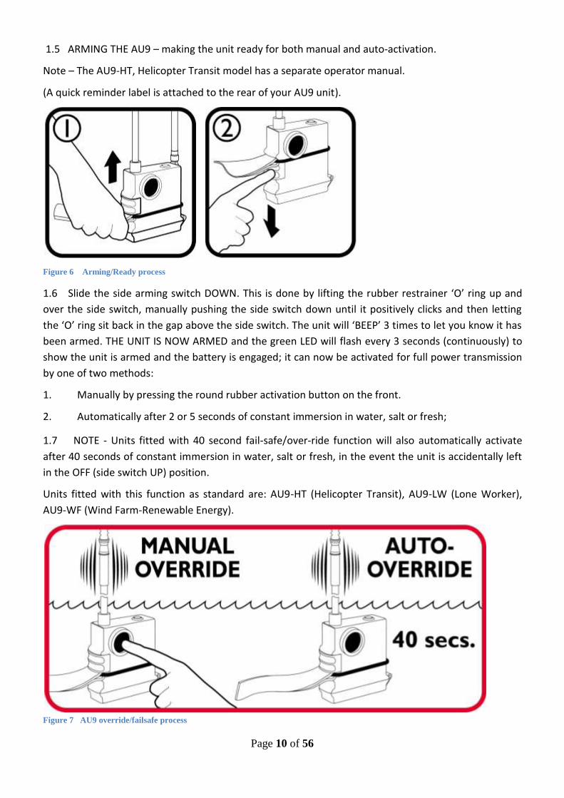
1.5 ARMING THE AU9 – making the unit ready for both manual and auto-activation.
Note – The AU9-HT, Helicopter Transit model has a separate operator manual.
(A quick reminder label is attached to the rear of your AU9 unit).
Figure 6 Arming/Ready process
1.6 Slide the side arming switch DOWN. This is done by lifting the rubber restrainer ‘O’ ring up and
over the side switch, manually pushing the side switch down until it positively clicks and then letting
the ‘O’ ring sit back in the gap above the side switch. The unit will ‘BEEP’ 3 times to let you know it has
been armed. THE UNIT IS NOW ARMED and the green LED will flash every 3 seconds (continuously) to
show the unit is armed and the battery is engaged; it can now be activated for full power transmission
by one of two methods:
1. Manually by pressing the round rubber activation button on the front.
2. Automatically after 2 or 5 seconds of constant immersion in water, salt or fresh;
1.7 NOTE - Units fitted with 40 second fail-safe/over-ride function will also automatically activate
after 40 seconds of constant immersion in water, salt or fresh, in the event the unit is accidentally left
in the OFF (side switch UP) position.
Units fitted with this function as standard are: AU9-HT (Helicopter Transit), AU9-LW (Lone Worker),
AU9-WF (Wind Farm-Renewable Energy).
Figure 7 AU9 override/failsafe process

Page 11 of 56
CAUTION- DO NOT STORE OR TRANSPORT IN A WET, HIGH MOISTURE LEVEL ENVIRONMENT.
1.8 HOW TO ACTIVATE THE AU9 WHEN IT IS ARMED/READY
To start full power transmission the following operations have to take place:
1.8.1 When the unit is ARMED the user firmly presses the centre of the round rubber button located
on the front of the unit. The unit will now transmit continuously until switched OFF which is achieved
by moving the side Arming Switch UP until it positively clicks.
Figure 8 AU9 Manual Activation process
1.8.2 Alternatively for automatic activation the user enters the water, after 5 seconds of continuous
immersion the unit will self activate and transmit continuously until switched off by moving the side
Arming Switch UP until it clicks, the unit will ‘BEEP’ and stop transmitting after a few seconds. NOTE –
some units will be programmed to auto-activate after 2 seconds immersion – refer to page 8.
Figure 9 AU9 - standard 5 second auto-activation process
NOTE – The unit has two waterpin sensors (metal screw on the top and metal screw in the base cap),
both these sensors have to be continuously immersed for a period of not less than 5 seconds to allow
the unit to wake up and auto-activate, this prevents inadvertent activation by spray, rain, splash.
1.8.3 What happens when the unit is transmitting on full power? The unit will make an intermittent
BEEPING sound and the antenna LED section will flash GREEN, followed by flashing RED LEDs in an SOS
pattern. This will continuously cycle until the unit is switched off.

Page 12 of 56
1.9 SWITCHING THE AU9 OFF
Figure 10 AU9 switch OFF process
1.9.1 Lift the rubber ‘O’ ring out and down, slide the side switch UP until it clicks. The unit will stop
transmitting within a few seconds; the unit will ‘BEEP’ once to indicate it has been switched OFF.
1.9.2 SWITCHING THE UNIT OFF FROM -40 second AUTOMATIC OVER RIDE-activation –
Move the side ARMING switch DOWN & then immediately back UP until it positively clicks. This applies
to units fitted with 40 second override function only, the instruction label on the rear of your unit will
indicate if your unit has this function installed or not (refer to page 8 for confirmation of model
type/features).
Figure 11 Switch OFF process for auto-override versio
2.0 TESTING THE AU9 – TRANSMISSION/BATTERY …& HOW OFTEN SHOULD I TEST MY AU9?
Figure 12 AU9 low power test procedure (TX=30m means the unit will transmitt a low power signal to approx 30m diameter)

Page 13 of 56
2.1 Checking the battery
The unit can be tested to check the battery status and also to check correct signal transmission, this is
achieved as follows:
Switch the unit OFF by sliding the side arming switch UP, the unit will ‘BLEEP’ once to indicate it is
switched OFF. With the unit switched ‘OFF’ the unit can be tested by pressing and holding down the
round rubber activation button on the front, the LEDs on the antenna will flash GREEN to indicate the
battery is OK, RED if the battery needs replacing and RED/GREEN if the battery is starting to run low. At
the same time the unit will transmit a low power signal on 121.5MHz which can be checked on a Sea
Marshall® Crewguard MKII receiver. NOTE - this low power signal will radiate to approx 30m around
you (tx = 30m on the label).
2.2 Automatic’ low battery’ indicator
As well as the above manual check the unit has an automated battery status indicator. In the idle state,
(when the Alerting Unit is not transmitting), the unit will automatically indicate it has a low powered
battery through the medium of a short infrequent ‘BEEP’ (nominally every 15 seconds), also a flashing
RED led. The battery should be replaced immediately. It is recommended you manually check your
batteries before and after every use.
2.3 Battery change process
A complete service/battery change pack is available from your local stockist.
Battery types:
AU9, ‘100mW’ = CR AA lithium, separate cells. NOTE – these are special batteries with
reverse terminals, check you have the terminals correctly aligned when fitting. The
manufacturer cannot be held responsible for damage caused by incorrect fitting of battery.
Figure 13a AU9 battery replacement procedures

Page 14 of 56
AU9, ‘500mW’ = CR AA Manganese dioxide lithium, battery pack with connector fitted
Figure 14b AU9 battery replacement procedures
2.4
At every battery change, check the base cap seal and base cap screw rubber gasket seal for damage.
Apply a film of silicon grease to the base cap seal on all sides so it is covered also the same to the base cap screw recess and seal. This should be done ‘every time’ the cap is opened up or the screw undone. Check the grease regularly. (the manufacturer cannot be held responsible for flooding caused by incorrect waterproofing)
Test your unit straight after changing the battery, or if the base cap screw has been undone or removed.
For 500mW versions only, use the sealed battery pack with connector cable.
Both battery types are available from the manufacturer or from your local stockist

Page 15 of 56
3.0 Checking the AU9 waterproofing seals and re-sealing the AU9?
Your AU9 surface use plb (refer to diver/sub-sea section for guidance) has a flat nitrile rubber seal fitted into the body, on some models this may be bonded into the main body of the unit in this case exclude stage 2 from the sequence below. In order to retain the waterproof integrity of your unit it is necessary to ensure the seal is covered with a film of silicon grease at all times. For units which have a removable seal this can be done as follows:
1. Carefully undo base cap screw, remove screw/seal and main seal from the body.
2. Clean channel the seal sits in with dry cloth or paper towel to remove old grease, clean rubber seal with a dry cloth or paper towel to remove old grease or dirt. Check for any damage, replace if damaged. If your unit has the seal bonded to the case leave this stage out of the process. Do not use a cleaning solvent
to remove the grease as this may damage the rubber seal.
3. Apply fresh grease over the whole seal, top/bottom/inside and outside edges, press seal firmly back into the channel recess in body and flatten all the way around. Ensure seal lays flat. Apply more silicon
grease over the top of the seal if required.
4. Remove base cap screw/seal, clean/replace as required. Apply grease over the screw/seal on all sides. Apply grease to the under side of the screw head. Do not apply grease over the outside surface of the
screw, this is a water sensor.
5. Close base cap and insert screw ‘very carefully’. Tighten screw very slowly (do not over tigthten).
6. Wipe away excess grease.
7. Test unit in accordance with this manual to ensure it is working correctly.

Page 16 of 56
4.0 How often should I test my Alerting Unit (SOS system)?
As described earlier in this section the AU9 has an inbuilt, automatic, battery warning indicator which will let you know when the battery needs replacing (refer 1.5.2). As well as testing/checking the battery, it is necessary to check the functionality of your units to ensure you catch any damaged or failed units. Ensure you carefully, visually inspect each unit regularly in order to check for signs of excessive wear and tear and or damage or broken seals. Immediately remove from service any unit which is damaged or has a fault. When the AU9 is switched OFF the transmitter can be tested on very low power by pressing and holding down the round activation button. In this mode the signal will only radiate to approx 30 to 50 metres from the Alerting Unit (refer to fig.11); the signal can be checked on one of the Sea Marshall® Base Unit receivers. To do this have the Base Unit receiver (Crewguard or SARfinder®), switched on and the Tone Detect function/button enabled, correct frequency selected...switch OFF the AU9 and press and hold the round activation button until the alarm triggers on the Base Unit, press the RESET button on the receiver and listen for the distinctive pulsing sound of the beacon signal through the loudspeaker. The signal strength indicator on the Base Unit will register the ‘SOS’ signal and show a series of green leds indicating the signal power; more lights = stronger signal (remember in this test mode the AU9it is a very low power transmission so may not show full signal strength). If your unit doesn’t activate the Base Unit it is faulty and will need to be serviced/repaired. Commerical operators who are maintaining a large number of PLBs normally have a Sea Marshall® Crewguard receiver located in their servicing/departure area or departure point which is used to regularly check their Alerting Units. It is the responsibility of the operator to decide how often they test the functionality of their MOB system. Ideally we recommend before and after each crew change or each shift, with regular ‘SOS’ (MOB/Lost Diver) practise/refresher sessions in each shift to ensure that all users are fully familiar and comfortable with how the system works.
5.0 BASE CAP SCREW INSERTED INDICATOR
The unit is programmed with a ‘BASE CAP SCREW NOT INSERTED’ indicator which through a series of
continuous ‘BEEPS’ shows:
5.1 The base cap has been closed (battery connection made) but the screw has not been inserted and
screwed into place. The bleeping can be cancelled by pressing the round manual activation button
firmly once.
NOTE: ensure the base cap is fully closed, the screw is fully tightened and the base cap is sealed with
silicone grease before the unit is put into service.
6.0 WEARING THE AU9
The Sea Marshall® AU9 unit can be worn in a number of different ways, some of which will increase
the tracking range by putting the end of the antenna in the best position (up and out of the water in a
vertical plain) for maximum signal propagation/signal strength. Always ensure the body of the AU9
will be under the waterline upon immersion to allow the auto-activation function to activate; the
automatic water sensors are the metal screws on the top and base cap of the AU9 body both of these
have to be immersed simultaneoulsy for the unit to automatically activate. The ground plane provided
by the water serves to amplify the signal giving a greater tracking range. The AU9 can be fitted to any
150 and 275N lifejacket or Personal flotation device. MRT offer a range of jackets with a pre-made
internal PLB pockets and antenna loops ask your re-seller for details or look at our product catalogue
for further details. The AU9 can also be fitted into an existing lifejacket by using a simple PLB pouch
with velcro waist belt loop, designed to fit and hold the body of the AU9 onto the waistbelt of a
Page 17 of 56
lifejacket, the antenna is then fed up into the lifejacket cover and up onto the bladder using reflexite
self-adhesive patches with elastic lopps as shown over the next few pages. The pouch is availabe from
your reseller or the manufacturer direct; some models come with the lifejacekt/pfd kit as standard.
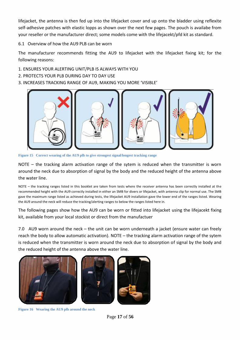
6.1 Overview of how the AU9 PLB can be worn
The manufacturer recommends fitting the AU9 to lifejacket with the lifejacket fixing kit; for the
following reasons:
1. ENSURES YOUR ALERTING UNIT/PLB IS ALWAYS WITH YOU
2. PROTECTS YOUR PLB DURING DAY TO DAY USE
3. INCREASES TRACKING RANGE OF AU9, MAKING YOU MORE ‘VISIBLE’
Figure 15 Correct wearing of the AU9 plb to give strongest signal/longest tracking range
NOTE – the tracking alarm activation range of the sytem is reduced when the transmitter is worn
around the neck due to absorption of signal by the body and the reduced height of the antenna above
the water line.
NOTE – the tracking ranges listed in this booklet are taken from tests where the receiver antenna has been correctly installed at the
recommended height with the AU9 correctly installed in either an SMB for divers or lifejacket, with antenna clip for normal use. The SMB
gave the maximum range listed as achieved during tests, the lifejacket AU9 installation gave the lower end of the ranges listed. Wearing
the AU9 around the neck will reduce the tracking/alerting ranges to below the ranges listed here in.
The following pages show how the AU9 can be worn or fitted into lifejacket using the lifejacekt fixing
kit, available from your local stockist or direct from the manufactuer
7.0 AU9 worn around the neck – the unit can be worn underneath a jacket (ensure water can freely
reach the body to allow automatic activation). NOTE – the tracking alarm activation range of the sytem
is reduced when the transmitter is worn around the neck due to absorption of signal by the body and
the reduced height of the antenna above the water line.
Figure 16 Wearing the AU9 plb around the neck

Page 18 of 56
8.0 AU9 unit fitted into a purpose built lifejacket with plb pocket/service window; Lifejacket model
shown – Mullion Hi-RISE ‘SOS’ 275N SOLAS twin chamber self righting.
Figure 17 AU9 fitted into lifejacket with plb pocket
8.1 By fitting the ‘reflective antenna patch’ the trackable ‘SOS’ signal of the AU9 is able to be
broadcast over a greater distance, making it easier for SAR crews to quickly locate you. Below are
several examples of HOW the AU9 can be fitted to a 150N and 275N lifejacket.
Figure 18 AU9 antenna examples of AU9 fitted to Mullion 'Hi-Rise' 275N SOLAS jacket
9.0 AU9 Antenna Lifejacket ‘Reflective Patch Fitting’ Process - for all inflatable style lifejacket types.
The plb lifejacket fixing kit includes 1 × plb pouch with velcro fastening for attaching the body of the
plb onto the waistband of your lifejacket, 3 × ‘reflexite – reflective/self adhesive antenna patches’ for
securing the antenna of your plb onto the bladder of the jacket. Below are examples of how the
antenna can be affixed to the bladder in 2 different ways.
Figure 19 lifejacket fixing kit
NOTE – before undertaking the antenna fixing process,
remove the gas bottles from the jacket to avoid
accidental inflation. Ensure when you replace the gas
bottles you screw them in as tightly as possible
checking that the threads are clear of obstructions and
are clean.
THE ANTENNA PATCHES ARE MADE FROM SOLAS APPROVED
REFELXITE SELF ADHESIVE REFLECTIVE PATCHES

Page 19 of 56
9.1 Attach the pouch to the waistband of the jacket and feed the antenna up inside the cover of the
jacket. Position the plb/pouch onto the left side of the jacket, left bladder so the antenna feeds straight
up into the jacket. If your jacket does not have a hole/aperture for the antenna to go up inside the cover
you will need to create a small hole in the rear cover; one way of doing this is carefully using a soldering
iron to create a small hole in the back of the cover which the antenna can slot through.
Figure 20 fixing lifejacket pouch
9.2 Inflate your lifejacket manually, this will allow you to see where to best place the antenna patches.
The aim is to have the end of the antenna/the spring positioned so that it will lift up towards the vertical
when the jacket inflates.
Figure 21
9.3 Example 1 – Apply the 2 patches to the TOPSIDE of the bladder so that the antenna runs up around
the bladder as indicated by + on fig. 21. Once you have decided the exact positioning slide the patch
onto the antenna cable and peel off the back paper to reveal the self adhesive surface (make sure the
jacket is fully inflated) apply the patch with an even firm pressure across each patch to ensure it is firmly
affixed without any wrinkles (when the jacket is deflated press each patch firmly against a hard surface).
If there is no existing
aperture make a
small hole in rear of
cover to feed the
antenna through.

Page 20 of 56
Figure 22
9.4 Apply the 3rd patch on the ‘top side’ of the bladder in a vertical postion so the antenna protrudes
above/to the side of the head (avoid putting the antenna in a postion which will cause the antenna to
press against the wearers head, point it away from the head). The patch can be applied over the top of
an existing reflexite patch.
Figure 23
NOTE – the self adhesive
patches can be trimmed
down to size to better fit,
using a pair of sharp scissors.
The patches can be applied
on top of existing reflexite
patches which may already
be applied to your jacket.

Page 21 of 56
10.0 Example 2 - shows how the end of the antenna can be postioned on the lower part of the
bladder by looping the antenna back on itself. When the jacket is inflated the antenna will be at the
opposite end of the jacket to the wearers head. Before using this method check there is space in the
bladder cover for the antenna when the jacekt is packed. THIS METHOD OF INSTALLTION WITH THE
FIRST PART OF THE ANTENNA UNDER THE BLADDER WILL REDUCE THE SIGNAL RANGE SLIGHTLY – THE
BEST METHOD IS TO RUN THE ANTENNA ACROSS THE TOPSIDE OF THE BLADDER.
10.1 Procedure – for this version, 2 of the patches are applied to the underside of the bladder side by
side and approxiamtely 10 to 15mm apart. Once you have decided the exact positioning slide the patch
onto the antenna cable and peel off the back paper to reveal the self adhesive surface (make sure the
jacket is fully inflated) apply the patch with an even pressure across each patch to ensure it is firmly
affixed without any wrinkles (when the jacket is deflated press each patch firmly against a hard
surface).
Figure 24
10.2 Apply the 3rd patch on the ‘top side’ of the bladder in a vertical postion so the antenna protrudes
from the lower end of the jacket (if necessary the patch can be applied over the top of an existing
reflexite patch).
Figure 25

Page 22 of 56
10.4 Step 4 Deflate and re-pack the jacket. IMPORTANT check that the antenna will deploy freely to
the intended position upon inflation.
Figure 26
10.5 Fitting the AU9 onto a ‘solid’ style PFD (personal flotation device)
Figure 27 AU9 fitted to pfd using lifejacekt fixing kit
The photographs above show how the AU9 can be fitted to a solid style lifejacket.
Step 1 – Attach the pouch to the waistband; put the AU9 into the pouch
Step 2 – Route the Antenna across the jacket and mark where the patches are to be placed, ensure the
antenna will be clearly abpve the water line upon immersion.
Step 3 – Apply patches firmly to each location and feed the antenna through

Page 23 of 56
11.0 ANTI-TAMPER BLANKING CAP
(cap supplied may differ in appearance to the one shown)
11.1 The dive pressure cap doubles as an anti-tamper cap that can be used to seal off the manual
activation button in order to make the unit automatic activation only. This can be useful to reduce the
risk of acccidental ‘manual’ activation in situations where the AU9 plb is being issued to an
inexperienced crew who are ‘likely’ to press the manual activation button or there is a risk of the
button being pressed by leaning on a sharp object.
Figure 28 AU9 auto-activation with pressure/anti-tamper cap fitted
12.0 MAINTENANCE
2.1 Check your unit regularly for the following:
1. Signs of excessive wear and tear to all physical components
2. Condition of waterproof seals (ensure they have silicon grease applied)
3. Battery status (refer to page 13 for battery testing)
2.2 Do not use your PLB if any of the above are damaged or do not function; contact the manufacturer
or your local supplier. Keep your unit clean and stored in the OFF position and dry at all times. For units
with the 40 second fail-safe function added, it is essential that the plb is stored in a relatively dry, low
moisture content environment. To clean your unit wash with pure water and use a mild hand cleaner if
required, dry thoroughly after use.
This unit could save your life; treat it with respect at all times.

Page 24 of 56
13.0 AU9-D ‘DIVE-Sub-Sea’ personal locator beacon
Figure 29
Figure 30 Sea Marshall Lost Diver System operation
13.1 The AU9 unit designed for diving is the AU9-D personal locator beacon comes in 2 versions:
1. AU9-D ‘80m’ depth rated - factory sealed (must be returned to factory for battery replacement)
2. AU9-D ‘40m’ depth rated – ‘O’ ring sealed, user replaceable battery
13.2 Each version of the AU9-D comes with the following extras as standard:
1 × rubber ‘bung style’ pressure cap which goes over the manual activation/test button
1 × spare side switch
1 × ‘diver carrying an SOS - plb’ notification card
13.3 A spares kit for the AU9-D consisting of the following items & can be purchased from your local stockist AU9-D spares kit contains thew following items:
2 × Rubber ‘bung style’ pressure cap
2 × ‘O’ ring base cap seal
2 × Base cap screw gasket seal
2 × Replacement side switch
1 × Tube of Silicone grease
NOTE - AU9 units with 40 second fail-safe override function cannot be used for diving,
these inlcude AU9-HT/Helicopter, AU9-LW/Lone Worker, AU9-WF/Windfarm _ Refer to page 8

Page 25 of 56
14.0 Fitting the pressure cap – converting the AU9 to auto-activation only
Figure 31 AU9 with pressure cap fitted
14.1 NOTE – your pressure cap may look different from the version shown in the photos in this
manual. The pressure cap is a simple ‘rubber bung’ arrangement sits over the round black manual
activation/test button on the front of the PLB and prevents the water pressure from pushing directly
against the unit’s test/manual activation button.
14.2 Fitting the cap is an easy process
Apply a thin film of silicone grease around the side of the rubber bung and under the outer lip.
Figure 32
Page 26 of 56
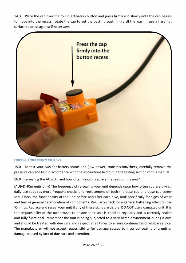
14.3 Place the cap over the round activation button and press firmly and slowly until the cap begins
to move into the recess, rotate the cap to get the best fit, push firmly all the way in; use a hard flat
surface to press against if necessary.
Figure 33 Fitting pressure cap to AU9
15.0 To test your AU9 for battery status and (low power) transmission/check, carefully remove the
pressure cap and test in accordance with the instructions laid out in the testing section of this manual.
16.0 Re-sealing the AU9-D… and how often should I replace the seals on my unit?
(AU9-D 40m units only) The frequency of re-sealing your unit depends upon how often you are diving;
daily use requires more frequent checks and replacement of both the base cap and base cap screw
seal. Check the functionality of the unit before and after each dive, look specifically for signs of wear
and tear or general deterioration of components. Regularly check for a general flattening effect on the
‘O’ rings. Replace and reseal your unit if any of these signs are visible. DO NOT use a damaged unit. It is
the responsibility of the owner/user to ensure their unit is checked regularly and is correctly sealed
and fully functional…remember the unit is being subjected to a very harsh environment during a dive
and should be treated with due care and respect at all times to ensure continued and reliable service.
The manufacturer will not accept resposnsibility for damage caused by incorrect sealing of a unit or
damage caused by lack of due care and attention.

Page 27 of 56
16.1 Re-sealing the AU9-D 40m – follow this procedure:
Figure 34
1. Carefully undo base cap screw, remove screw/seal and main seal from the body.
2. Clean channel the seal sits in with dry cloth or paper towel to remove old grease, clean rubber seal
with a dry cloth or paper towel to remove old grease or dirt. Check for any damage, replace if
damaged. Do not use a cleaning solvent to remove the grease as this may damage the rubber seal.
3. Apply fresh grease over the whole seal, top/bottom/inside and outside edges, press seal firmly back
into the channel recess in body and flatten all the way around. Ensure seal lays flat. Apply more silicon
grease over the top of the seal if required.
4. Remove base cap screw/seal, clean/replace as required. Apply grease over the screw/seal on all
sides. Apply grease to the under side of the screw head. Do not apply grease over the outside surface of the
screw, this is a water sensor.
5. Close base cap and insert screw ‘very carefully’. Tighten screw very slowly (do not over tigthten).
6. Wipe away excess grease.
7. Test unit in accordance with this manual to ensure it is working correctly.
Page 28 of 56
17.0 USING THE AU9-D WITH PRESSURE CAP (anti-tamper cap) FITTED
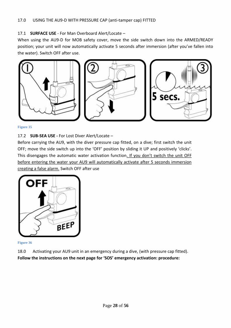
17.1 SURFACE USE - For Man Overboard Alert/Locate –
When using the AU9-D for MOB safety cover, move the side switch down into the ARMED/READY
position; your unit will now automatically activate 5 seconds after immersion (after you’ve fallen into
the water). Switch OFF after use.
Figure 35
17.2 SUB-SEA USE - For Lost Diver Alert/Locate –
Before carrying the AU9, with the diver pressure cap fitted, on a dive; first switch the unit
OFF; move the side switch up into the ‘OFF’ position by sliding it UP and positively ‘clicks’.
This disengages the automatic water activation function. If you don’t switch the unit OFF
before entering the water your AU9 will automatically activate after 5 seconds immersion
creating a false alarm. Switch OFF after use
Figure 36
18.0 Activating your AU9 unit in an emergency during a dive, (with pressure cap fitted).
Follow the instructions on the next page for ‘SOS’ emergency activation: procedure:

Page 29 of 56
INITIATING ‘SOS’ EMERGENCY TRANSMISSION WITH PRESSURE CAP FITTED
1. Arm the unit; lift the ‘grab tag’ out and pushing the side switch down.
Figure 37
2. Click the side switch down firmly into place.
Figure 38
3. Immerse the unit continuously in water for not less than 5 to 10
seconds. The unit will start transmitting, LEDS will flash RED continuously.
Figure 39
Figure 40

Page 30 of 56
19.0 The AU9 can be used either on it’s own or it can be attached to a diver surface marker
buoy/SMB (recommended); a special SMB with antenna guide loops and PLB pocket is available
through your local stockist. By attaching your AU9 plb unit into an SMB and attaching a line to the
SMB, the AU9 PLB can be used to raise the alarm from the sea bed in the event of difficulties.
19.1 How to use the AU9 when fitted to a surface marker bouy.
Figure 41 Using the Surface Marker Bouy with AU9/PLB fitted
1. Diver descends.
2. Diver gets into difficulties at depth. Activate AU9 by sliding side switch DOWN, attach SMB to line
and send AU9/SMB to surface.
3. AU9 will arrive on surface already transmitting, pull line tight to ensure SMB remains vertical.
4. SARfinder on dive boat within range will activate notifying crew of an ‘SOS’ emergency. SARfinder
will display direction of SOS signal and approximate range.
20.0 IMPORTANT – It is advised that when using the AU9 plb for diving that it is fitted to an SMB in
order to give the maximum possible transmission distance by extending the antenna up vertically.
With the AU9 fitted to an SMB the unit can be deployed on a line from under the water, at depth,
already transmitting when the AU9 hits the surface it will activate the alarm on the dive boat alerting
them immediately of an emergncy. This combination means the dive boat will be already searching for
you by the time you reach the surface after decompressing… saving valuable minutes in an emergency
situation. Ity also provides a very visible marker for the final 0.5km of a search. Using the AU9 without
the SMB will restrict the tracking range.

Page 31 of 56
21.0 AU9-D fitted to Surface Marker Bouy
Figure 42 AU9 fitted to surface marker bouy (SMB)
AU9 shown rolled up inside the Surface Marker Bouy… small and compact; allows the alarm to be raised from the sea bed (when attached to a line)…saving valuable
minutes in a rescue.
Enhances the range of the system when used on the surface by lifting the antenna up high.
LED strobe on the AU9
antenna:

Page 32 of 56
22.0 Your AU9 can be used on it’s own to provide an ‘SOS’ homing signal for the Coastguard SAR to
home into once they have been notified you are missing, or it can be used as part of a ‘self managed
lost diver locating system’ which utilises a dedicated monitor/directional homing unit fitted to the dive
boat, called a SARfinder®. The SARfinder will monitor for an ‘SOS’ signal from an AU9 plb and give the
direction of the signal along with approximate range indication.
Figure 43 Sea Marshall SARfinder® locator unit
Figure 44 Storyboard guide to self managed diver alert and locating system
22.1 The SARfinder® has an NMEA output which when connected to the boats GPS plotter will
automatically plot the position of the boat at the time the ‘SOS’ transmission was received giving a
starting point for the search, for more information refer to operator manual.

Page 33 of 56
23.0 WEARING THE AU9-D
Take care not to crease sharply the end of the antenna this will break internal spring. It is ok to roll the
antenna spring tightly up inside an SMB. Ensure your unit is positioned in an easy to reach place should
you need to deploy the unit quickly. In order to provide a strong ‘SOS’ signal for rescuers to home into,
when activated, the antenna of your AU9 should be positioned out of the water (i.e. above the water
line) as much as possible. The AU9 will not transmit a trackable signal with the antenna completely
submerged. It is recommended that for diving the AU9 is used in conjunction with the ‘SOS’ surface
marker bouy, this combination will give the longest tracking range and allow you to deploy the AU9
from the sea bed (when attached to a line) in an emergency…saving valuable minutes in a rescue
where decompression will delay the tiome to reach the surface and raise the alarm.
Figure 45 recommended way to wear the AU9 plb
24.0 MAINTENANCE
Wash your AU9 with fresh water after each dive Keep your AU9 clean at all times (use a gentle
hand wash to clean your unit)
Check functionality/batteries before and after every dive.
Do not dive with an unchecked/untested/damaged unit.
Do not crease the antenna (it is ok to roll the antenna up inside an SMB)
Regularly check the silicon grease/sealing of the following (before and after each dive)
Base cap
Pressure cap (and manual activation button)
Base cap screw
…re-apply grease as required.
Page 34 of 56
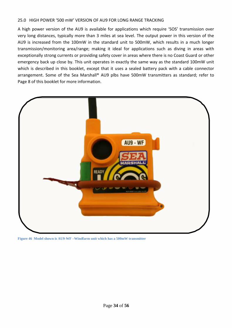
25.0 HIGH POWER ‘500 mW’ VERSION OF AU9 FOR LONG RANGE TRACKING
A high power version of the AU9 is available for applications which require ‘SOS’ transmission over
very long distances, typically more than 3 miles at sea level. The output power in this version of the
AU9 is increased from the 100mW in the standard unit to 500mW, which results in a much longer
transmission/monitoring area/range; making it ideal for applications such as diving in areas with
exceptionally strong currents or providing safety cover in areas where there is no Coast Guard or other
emergency back up close by. This unit operates in exactly the same way as the standard 100mW unit
which is described in this booklet, except that it uses a sealed battery pack with a cable connector
arrangement. Some of the Sea Marshall® AU9 plbs have 500mW transmitters as standard; refer to
Page 8 of this booklet for more information.
Figure 46 Model shown is AU9-WF –Windfarm unit which has a 500mW transmitter

Page 35 of 56
26.0
Figure 47
RECOMMENDED FOR DIVERS
& long range offshore workers
NOTE – the tracking ranges listed are taken from tests where the receiver antenna has been correctly installed at the recommended
height with the AU9 correctly installed in either an SMB for divers or lifejacket, with antenna clip for normal use. The SMB gave the
maximum range listed as achieved during tests, the lifejacket AU9 installation gave the lower end of the ranges listed. Wearing the AU9
around the neck will reduce the tracking/alerting ranges to below the ranges listed here in.

Page 36 of 56
27.0 Glossary of terms
27.1 MSLD – Maritime Survivor Locating Device – A Phrase generated from the USA to describe a self
managed Man Overboard/Lost Diver Alert & Locating system. System comprises AU (Alerting Unit-
Transmitter) and BU (Base Unit- Reciver/Locator)
27.2 NMEA 0183 (or NMEA for short) is a combined electrical and data specification for
communication between marine electronic devices such as echo sounder, sonars, anemometer (wind
speed and direction), gyrocompass, autopilot, GPS receivers and many other types of instruments
27.3 PLB – Personal Locator Beacon
27.4 SAR – Search and Rescue
27.5 121.5MHz – International Search and Rescue homing frequency

Page 37 of 56

Page 38 of 56
Contents
Pages Description
39 Declaration Of Conformity
39 Declaration Of Compliance
with ED-14F (part)
40 – 48 Section 1 AU9-HT operator instructions
49 – 51 Section 2 Maintenance guidelines
52 Section 3 Servicing procedures
53 Section 4 Repair procedures
54 NOTES
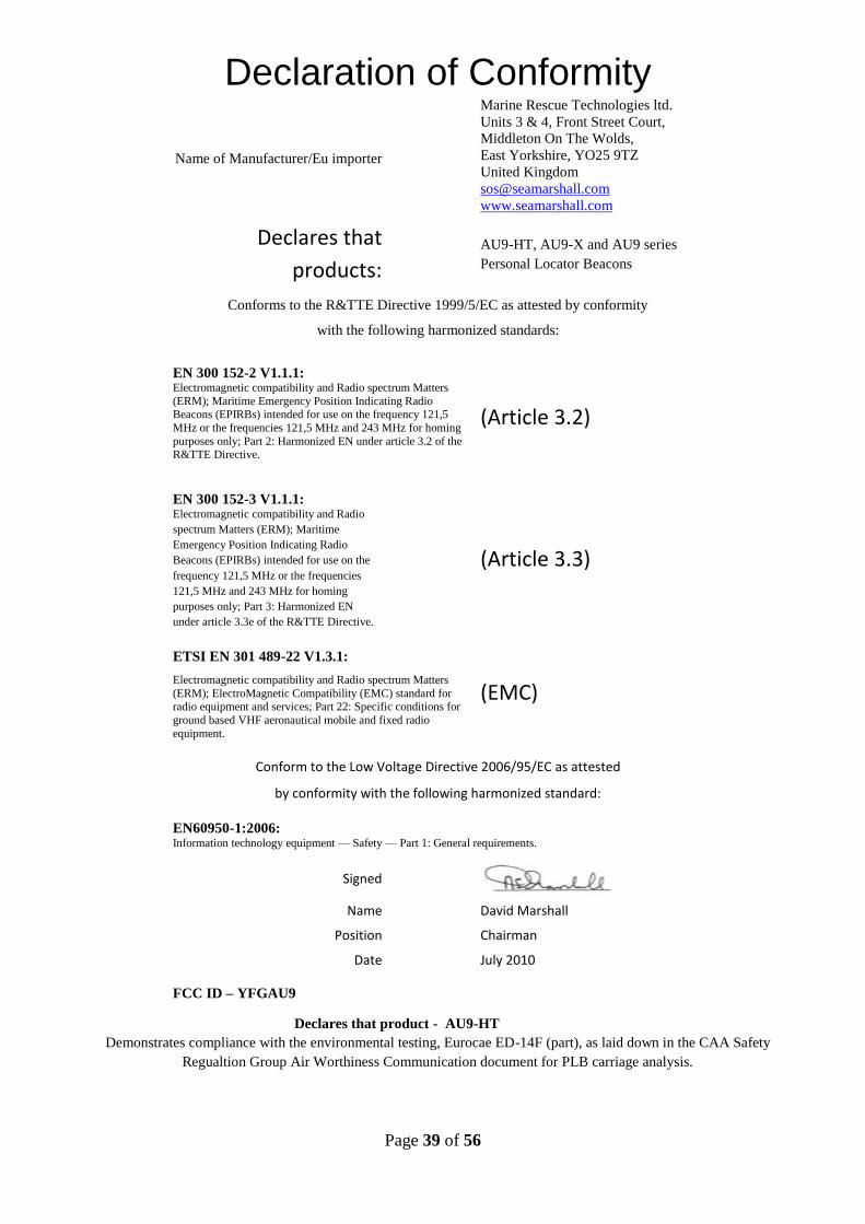
Page 39 of 56
Declaration of Conformity
Name of Manufacturer/Eu importer
Marine Rescue Technologies ltd.
Units 3 & 4, Front Street Court,
Middleton On The Wolds,
East Yorkshire, YO25 9TZ
United Kingdom
www.seamarshall.com
Declares that
products: AU9-HT, AU9-X and AU9 series
Personal Locator Beacons
Conforms to the R&TTE Directive 1999/5/EC as attested by conformity
with the following harmonized standards:
EN 300 152-2 V1.1.1: Electromagnetic compatibility and Radio spectrum Matters
(ERM); Maritime Emergency Position Indicating Radio Beacons (EPIRBs) intended for use on the frequency 121,5
MHz or the frequencies 121,5 MHz and 243 MHz for homing
purposes only; Part 2: Harmonized EN under article 3.2 of the R&TTE Directive.
(Article 3.2)
EN 300 152-3 V1.1.1: Electromagnetic compatibility and Radio
spectrum Matters (ERM); Maritime
Emergency Position Indicating Radio
Beacons (EPIRBs) intended for use on the
frequency 121,5 MHz or the frequencies
121,5 MHz and 243 MHz for homing
purposes only; Part 3: Harmonized EN
under article 3.3e of the R&TTE Directive.
(Article 3.3)
ETSI EN 301 489-22 V1.3.1:
Electromagnetic compatibility and Radio spectrum Matters
(ERM); ElectroMagnetic Compatibility (EMC) standard for radio equipment and services; Part 22: Specific conditions for
ground based VHF aeronautical mobile and fixed radio
equipment.
(EMC)
Conform to the Low Voltage Directive 2006/95/EC as attested
by conformity with the following harmonized standard:
EN60950-1:2006: Information technology equipment — Safety — Part 1: General requirements.
Signed
Name David Marshall
Position Chairman
Date July 2010
FCC ID – YFGAU9
Declares that product - AU9-HT
Demonstrates compliance with the environmental testing, Eurocae ED-14F (part), as laid down in the CAA Safety
Regualtion Group Air Worthiness Communication document for PLB carriage analysis.

Page 40 of 56
Section 1
Operating Instructions 1.1.0 AU9-HT OVERVIEW
The Sea Marshall® AU9-HT, Alerting Unit series 9 helicopter transit (PLB), has been
designed to fullfill the requirement of the offshore helicopter transit market for a long
lasting, high quality, robust high powered 121.5MHz personal locator beacon. Colour – Orange body, RED side switch, Black antenna.
Fig. 1.0

Page 41 of 56
1.1.1 BACKGROUND
Fig. 2.0
The AU9-HT is a development derived from the well known ISPLB8 Sea Marshall® personal
locator beacon, it ustilises the same format of operation so as to retain some consistency of
user familiarity and function in the field. In all other respects the AU9-HT unit is a completely
new more advanced unit.
1.1.2 SPECIFICATIONS
Frequency: 121.5 MHz
Battery: 2 × 3V lithium CR AA pack, user replaceable. Automatic low warning indicator/LED
Battery 10 year life (recommended change out after 5 years, 50% of duty cycle)
Endurance: average 24-30 hours transmitting (60 months ‘approx’ on standby/armed)
Product Expected lifespan 10 years (with correct service and maintenance as laid out here in)
Dimensions : 90mm high × 70mm wide(body) 80mm hinge/base cap × 35mm deep
Modulation: Continuous swept tone A3X
Output power: 100mW
Temp range (storage): -55°C to + 70°C;
Approvals - CE, ED14-F part
Test Units: 121.65MHz and 121.775MHz
Activation - Manual & Automatic with manual over ride (salt and fresh water)
Antenna: 1m cable with flexible helical spring section, adaptable for lifejacket fitting
Strobe: inbuilt LED strobe on antenna flashes ‘SOS’.
ILS: internal loudspeaker 80dB
Weigth: 250gms (approx)

Page 42 of 56
1.2.0 OPERATING THE AU9-HT
The following sections cover how to use the unit on a day to day basis. Here is an enlarged
version of the rear instruction label.
Fig. 3.0
1.2.1 ARMING THE UNIT – making the unit ready for manual or auto-activation
Fig 4.0
1.2.2 Slide the side arming switch DOWN (no. 11). This is done by lifting the rubber restrainer
‘O’ ring
(no. 6) up and over the side switch, manually pushing the side switch (no. 11) down until it
positively clicks and then letting the ‘O’ ring sit back in the gap above the side switch. The unit
will ‘BEEP’ 3 times to let you know it has been armed. THE UNIT IS NOW ARMED and the green
LED will flash every 3 seconds continuously to show unit that the unit is armed and the battery
is engaged; it can now be activated manually by pressing the round rubber activation button on
the front (no. 12) or automativally after 5 seconds of constant immersion in water (salt or
fresh), water sensor pins (no. 3 & 9).

Page 43 of 56
1.3.0 HOW TO ACTIVATE THE UNIT WHEN IT IS ARMED
To start full power transmission the following operations have to take place:
1.3.1 When the unit is ARMED the user firmly presses the round rubber button on the front of
the unit (no 10). The unit will now transmit continuously until switched off by moving the side
Arming Switch (no. 11) UP until it positively clicks. NOTE a round securing ring has been added around the inside
edge of this button to reduce the risk of. Inadvertent activation.
Fig. 5.0
1.3.2 Alternatively for automatic activation the user enters the water, after 5 seconds of
continuous immersion the unit will self activate and transmitt continuously until switched off by
moving the side Arming Switch (no. 11) UP until it clicks, the unit will ‘BEEP’ and stop
transmitting after a few seconds.
Fig. 7.0
NOTE – The unit has two waterpin sensors, (no. 3 & 9), both these sensors have to be
continuously immersed for a period of not less than 5 seconds to allow the unit to wake up and
auto-activate, this prevents inadvertant activation by spray, rain, splash.
1.3.4 What happens when the unit is transmitting on full power? The unit will make a BEEPING
sound and the antenna LED section will flash GREEN, , followed by flashing RED LEDs in an SOS
pattern this will continuously cycle until the unit is switched off.

Page 44 of 56
1.4.0 SWITCHING THE UNIT OFF – disengaging the battery
Fig. 8.0
1.4.1 Lift the rubber ‘O’ ring (no. 6) out and down, slide the side switch (no. 11) UP until it
clicks. The unit will stop transmitting within a few seconds, the unit will ‘BEEP’ once to indicate it
has been switched OFF.
1.5.0 OVER RIDE FUNCTIONS
1.5.1 The unit has been programmed with automatic and manual over-ride functions. The logic
behind this is two-fold:
1. To allow the unit to be carried during flight in the OFF position with the battery disengaged
thereby removing all potential risk of inadvertant activation.
2. To provide a fail-safe in the event the user enters the water with the unit accidentally
switched OFF, particulary if they are rendered unconscious or suffer from cold shock response.
The overide functions work as follows;
Fig. 9.0 (NOTE – the unit will function as per 1.3.4)

Page 45 of 56
1.5.3 MANUAL OVERRIDE – When the unit is Switched OFF, if the user enters the water and the
unit is immersed continuously they can manually overide the unit and enable full power
transmission by pressing the round activation button on the front (no. 12).
1.5.4 AUTOMATIC OVERRIDE (Fail-Safe) – When the unit is switched OFF should the person
enter the water in an unconscious state the unit will wake up when immersed continuoulsy for a
period of no less than 120 seconds and automatically begin transmitting.
1.5.5 SWITCHING THE UNIT OFF FROM AUTOMATIC OVER RIDE ACTIVATION - The unit will
continue to transmitt on full power until manually switched OFF by moving the side ARMING
switch (no.11) DOWN & then immedaitely back UP until it positively clicks.

Page 46 of 56
1.6.0 TESTING THE UNIT
Fig. 10.0
Fig. 11.0
1.6.1 CHECKING THE BATTERY
The unit can be tested to check the battery status and also to check correct signal transmission,
this is achieved as follows:
Switch the unit OFF by sliding the side arming switch UP, the unit will ‘BLEEP’ once to indicate it
is switched OFF. With the unit switched ‘OFF’ the unit can be tested by pressing and holding
down the round rubber activation button on the front, the LEDs on the antenna will flash GREEN
to indicate the battery is OK, RED if the battery needs replacing and RED/GREEN if the battery is
starting to run low. At the same time the unit will transmit a low power signal on 121.5MHz
which can be checked on a Sea Marshall® Crewguard MKII receiver. NOTE - this low power signal
will radiate to approx 30m around you.
1.6.2 LOW BATTERY INDICATOR
As well as the above manual check the unit has an automated battery status indicator. In the
idle state, when the unit is not transmitting, the unit will automatically indicate it has a low
powered battery through the medium of a short infrequent ‘BEEP’ (nominally every 15
seconds), also a flashing RED led. The battery should be replaced immediately.

Page 47 of 56
1.6.3 HOW TO CHANGE THE BATTERY
Battery type CR AA lithium, available from the manufacturer. NOTE – these are special batteries
with terminals reversed.
NOTE – The base cap seal and surrounding area MUST be covered with silicon grease, also the
base cap screw and seal must also be thoroughly sealed with silicon grease to maintain
waterproof integrity of the unit. Wipe off excess grease from the outside of the unit. Do not
overtighten the base cap screw. Test the unit once the new battery is in place, refer to 1.6.1
above.
1.7.0 BASE CAP SCREW INSERTED INDICATOR
The unit is programmed with a ‘BASE CAP SCREW NOT INSERTED’ indicator which through a
series of continuous ‘BEEPS’ shows:
1.7.1 The base cap has been closed (battery connection made) but the screw has not been
inserted
NOTE: ensure the base cap is fully closed, the screw is fully tightened and the base cap is sealed
with silicon grease before the unit is put into service.
1.8.0 WEARING THE AU9-HT
Unless advised otherwise, the Sea Marshall® AU9-HT unit is to be worn fitted into a flotation
garment of some kind, for example the SHARK LAP jacket. Ensure the antenna of the unit is
positioned up against the body in a vertical position and the control box is lower down the body
so that it will be below water level should you enter the water. This will ensure the auto-
activation function will freely enable upon entering the water and that the maximum signal
transmission strength will occur.
Fig. 12.0
The unit can be worn around the neck in a necklace fashion by connecting the end loop located
at the end of the antenna spring back onto the clip at the top right side of the body NOTE – the
trackable signal will be reduced by wearing it as a loop around the neck.
Refer to your service provider for further guidance.

Page 48 of 56
1.9.0 BLANKING CAP FITTED
Your unit may be suppied with a blanking cap fitted over the manual activation/test button. In
this configuration the unit ‘Auto-Activation’ only (5 seconds of continuous immersion). Once
activated the unit will continue transmitting until manually switched OFF by sliding the side
switch UP.
To test the unit, remove the blanking cap and test in accordance with 1.6. Make sure the button
is dry before repalcing cap. To replace cap, place the cap flat over the raised section and press
firmly down unitl it sits tightly in place.

Page 49 of 56
Section 2
Maintenance Guidelines 2.1.0 MAINTAINING OPTIMUM PERFORMANCE
By following the guidelines contained here in the expected lifespan of an AU9-HT unit should be
10 or more years. To ensure continued optimum performance of your unit the manufacturer
recomends the following checks are included and carried out as part of the standard daily
operating routine:
Fig. 13

Page 50 of 56
2.1.1 VISUAL INSPECTION FOR DAMAGE & WEAR & TEAR
Look for signs of excessive wear and tear and also damage caused outside of normal wear and
tear. Check CLOSELY each of the components listed in Fig. 7.0 on page 10.
2.1.2 Frequency
To be undertaken at weekly intervals or less.
2.1.3 Action
If any component shows signs of excessive wear and tear or damage the unit should be
removed from service immediatley and if necessary returned to the manufacturer for repair. NOTE – the base cap seal is internal, accessed by removing the base cap screw.
NOTE – the base cap screw seal is internal, accessed by removing the base cap screw.
NOTE – the unit will BLEEP unitl the base cap/screw is replaced, this can be disengaged by opeing the base cap fully and disengaging
the battery.
2.2.0 BATTERY & FUNCTIONALITY CHECK
Testing the PLB on low power to check the radiated signal and battery status, refer to section
1.6.0. The batteries have a 10 year shelf life, the manufacturer recomends they are replaced
after 5 years, 50% of the duty cycle, or sooner as required. Follow middle left box:
Fig. 14.0

Page 51 of 56
2.2.1 Frequency
To be undertaken BEFORE and AFTER each flight in alignment with the service providers
guidelines for flight use, unless otherwise advised.
2.2.2 Action
If the unit indicates the battery is low the unit should immediatley be removed from service and
the battery replaced by the service provider. If the unit fails to transmit a low power signal it
should be immediately removed from service and returned to the manufacturer for
repair/replacement. .
2.3.0 WATERPROOFING CHECK
The base cap rubber seal and base cap screw ‘O’ ring seal should always be covered with silicon
grease. The base cap closure section should also be sealed with a small amount of silicon grease
to prevent dust and grit penetrating between the cap and the body. This grease should be
replaced at regular intervals (monthly) or more frequently if deemed necessary by the service
agent. The unit should not be entered for service without silicon grease applied.
2.3.1 Frequency
As required, guided by the visual inspection in 2.1.1
2.3.2 Action
BASE CAP -Wipe away existing grease and apply a bead of grease over the base cap seal and
around the edge and uderside of the seal. Make sure the gap between the base cap and the
body is filled with silicon grease.
BASE CAP SCREW – Wipe away the existing grease and replace with fresh silicon grease.

Page 52 of 56
Section 3
Servicing Procedures To ensure continued performance of your unit the manufacturer recomends the following
services are included and carried out as part of the standard operating routine:
1. Once a year the unit should be fully inspected as per 2.1.1 for signs of wear and tear. If required
the unit is to be either returned to manufacturer or the appointed service centre for
repair/replacement as required. If the unit is functioning correctly it can continue to be used in
service.
2. A full service/battery replacement/ inspection facilty is available from the manufacturer. The
manufacturers service package consists of:
Replace battery
Replace base cap seal & re-grease
Replace base cap screw seal & re-grease
Replace side Arming switch
Replace arm switch restrainer ‘O’ ring
New battery fitted date label applied
Full service and performance check
Signed off for return to service
MRT ltd. will aim to turn around all PLBs put in for service in less than 7 days.
If repairs are required MRT ltd. will notify the customer or their service provider.

Page 53 of 56
Section 4
Repair Procedures To ensure continued performance of your unit the manufacturer recommends the following
repair procedures are included and carried out as part of the standard operating routine :
1. In the event of a component being identified as failing the unit be taken from service and
returned to the manufacturer for repair or replacement.
MRT ltd. will aim to turn all PLBs put in for repair in less than 7 days.
NOTES

Page 54 of 56
Page 55 of 56
Warranty
Your unit is covered by a standard 1 year parts and labour warranty. Marine Rescue Technologies Ltd (MRT) warrants to the
purchaser that the products conform to manufacturers specifications and that the products are free of defects on materials and
workmanship for a period of one year from the date delivered to the customer/end user. In the event of a defect, due to faulty
material, design or construction, the customer will return to MRT at the business address were we, or the manufacturer will
undertake, at our choice, a repair or replacement. Warranty covers all parts, materials and labour, provided that the product is
returned to our works. Exclusions: damage caused by other than normal use and lack of general care and attention or incorrect
sealing of the unit carried out in accordance with this instruction manual. MRT Ltd. does not accept any responsibility or any
claim for direct or indirect consequences of defects of the equipment, either during the guarantee period or at a later stage.
Repairs
MRT ltd. offers a full and comprehensive service and repair facility with fast turn around.
NOTE any units which are not repaired/collected/returned after a 3 month period from date of receipt will be destroyed.
Disclaimer
The Sea Marshall® products are an aid to recovery only, it is the repsonsibility of the user/operator to ensure they are fully
conversant with the operation of the equipment and the equipment is kept in full working order at all times combined with
functionality and damage checks before and after each use. MRT Ltd. does not accept liability for loss of life or injury caused
during any accident during which the equipment is being used, how so ever it arises.Sea Marshall® Alerting Units/MSLDs are an
‘Aid to rescue only’, they do not guarantee your safety. The Sea Marshall® MSLDs will dramatically increase the chances of
detection and location of a Man Over Board. Personal safety remains at all times the sole responsibility of the individual. It is the
responsibility of the individual to inform their local Coast Guard, their senior personnel/crew members and or family of their
intended location/destination and estimated duration of journey. It is also the responsibility of the individual to notify these people
of the type of safety equipment they will be carrying. In the case of accidental activation the user should de-activate the unit and
notify the appropriate Search And Rescue Authority.

Page 56 of 56