Embed Size (px)
Citation preview

Page 1 of 6 Module #2: Name Drawing 8e CAD#11: Date
View Tutorial 8e: Circles, Arcs, Ellipses, Rotate, Explode, & More Dimensions Objective: Design a wing of the Guggenheim Museum.
Copyright 2001. All rights reserved. 52
Introduction The drawing used for this tutorial comes from Clark R. and M.Pause, "Precedents in Architecture", VNR 1985, page 135.
In this tutorial you will learn how to edit graphics(!) and about setting model space limits. You will draw a simple plan based on Frank Lloyd Wright's 1956 (New York) Guggenheim Museum.
Stephen Peter of the University of South Wales developed the content of this assignment.
Please note that the dimensions used in this tutorial are neither accurate nor correct! I don't have access to an accurately dimensioned drawing of the building so I've guessed the dimensions...
Starting AutoCAD
On my computer, the bottom-left coordinate was 0,0,0 and the top-right coordinate was 514,296,0.
Start AutoCAD, and then move the cursor to the bottom left of the screen, you will note the coordinates (on the status line) go down to near 0,0. In the version I am using the drawing limits are set to the size (in millimeters) of an A3 sheet of paper (420,297).
Setting the Limits and Units
It is normal when using AutoCAD to draw objects full size, so it's usually necessary to reset the drawing limits to (about) the size of the object being drawn (or in the case of a building the building's site). Type:
Alternatively, select Format - Drawing Limits and then type the numbers shown.
limits 0,0 50000,50000
This sets the drawing "size" to 50x50 meters.
If the coordinates in the status area didn't change to no decimal places, move the mouse!
Next we need to get rid of the 4 decimal points! Select "Format - Units...", AutoCAD will display the "Drawing Units" dialog. Make sure Decimal is selected in the Units section and Decimal Degrees in the Angles section, then in Unit's Precision, click on the down arrow beside "0.0000" and select "0", and finally select "OK".
Zoom All Zoom Window
Z is the alias (shortcut) for ZOOM. Remember that [space] is the same as
.
This sets the "model space" dimensions. To reset the drawing view to the whole of the (empty) drawing, select the zoom-all icon, which is hiding under the zoom-window icon (on the standard toolbar) - hold the button down and then rest of the zoom toolbar is displayed (or type: Z [space] A [space] ).
Move the cursor around now and note that the coordinates are now bigger numbers!
Let the Drawing Begin!!
This shows us the "drawing area". Firstly draw a rectangle from 0,0 to 50000,50000, you should remember how to do that from the first tutorial!
Circle "C" is the alias for CIRCLE.
Then draw a circle, centered at 30000,24000 with a 6000 radius. Select circle (or type: C ), then type: 30000,24000 the circle e 6000 the circle radius

Page 2 of 6 Module #2: Name Drawing 8e CAD#11: Date
View Tutorial 8e: Circles, Arcs, Ellipses, Rotate, Explode, & More Dimensions Objective: Design a wing of the Guggenheim Museum.
Copyright 2001. All rights reserved. 53
Center snap To get AutoCAD to display the Object Snap Modes toolbar, select "Toolbars" from the "View" menu and then select "Object Snap".
Next you will draw another circle, with the same center, but with a 9500 radius. Press: to "recall" the last command. Select the center snap mode (or type: CEN ), then pick the first circle (NOT the center of the circle), then type: 9500 the circle radius
Draw the Building "Wing" Hopefully you remember how!! Next draw a rectangle from the center of the circles to 39500,33500.
Hint: use a relative coordinate @1500,9500.
Once you have done that draw another rectangle to the right of the last, start at 39500,24000 and make the rectangle 1500x9500.
You might find the following section easier if you turn object snapping ON (make sure "OSNAP" is 0N in the status area). Endpoint Snap Midpoint Snap
Now you will draw an arc on the end of the last rectangle (see figure 1). Select Draw - Arc - Start-Center-End, then select the Endpoint snap mode (or type: END ) and select the bottom-right of the last rectangle. For the center point of the Arc, select the Midpoint Snap Mode (or type: MID ) and select the middle of the right edge of the last rectangle. For the end of the Arc, select the Endpoint Snap Mode and select the top-right of the rectangle.
Figure 1 Showing the location of the ARC.
Save the drawing Save Save the drawing: select the save icon (or type: QSAVE ), when you are
prompted for a drawing name, select the your student folder on the network and type in CAD11 for the drawing name and select "OK".
Copy & Rotate the Building Wing
The array command is used to copy one or more objects in either a rectangular or circular pattern and when a circular pattern is used the objects can be rotated; it can be an incredibly powerful command.
Now we want to copy & rotate the two rectangles and the arc (3 times), AutoCAD provides the array command to achieve this.
Select Modify - Array, AutoCAD will prompt for the objects to be selected: click below and to the left of the bottom-left corner of the left rectangle and then move the mouse until the selection rectangle encloses the two rectangles and the arc - then click the mouse button (3 objects should be selected). Then press to end the selection process.

Page 3 of 6 Module #2: Name Drawing 8e CAD#11: Date
View Tutorial 8e: Circles, Arcs, Ellipses, Rotate, Explode, & More Dimensions Objective: Design a wing of the Guggenheim Museum.
Copyright 2001. All rights reserved. 54
Center snap After selecting the Center snap mode, pick the circle NOT the center!
AutoCAD will then prompt for the type of Array - rectangular or polar, type: P for polar. Then use the Center snap mode to select the center of the circles. Then type: 4 the number of items (including the existing item)
accept 360 degrees accept "rotate as copied"
Exploding Objects! For convenience, in the following section, I'll talk of the "top-right wing" and the "bottom- right wing". By the "top-right wing" I mean the first rectangles and arc that you drew, and the "bottom-right wing" is the rectangles and arc in the bottom-right corner!!
Now we need to erase some of the lines we've drawn. When the rectangle command is used the rectangle that is drawn is a "polyline" which means that all the lines that make up the object are joined together, the lines must be "exploded" before any parts of the rectangle can be erased.
Explode Be aware that explode does not appear to do anything! It doesn't say - "yes, I've done that" and the display doesn't change, but AutoCAD will display an error message if it failed to explode the objects.
Select explode from the modify toolbar (or type X which is the alias for "explode") select both the rectangles in the "top-right corner" and then press . If AutoCAD doesn't display any error messages then the explode command worked!
Erasing Objects We need to delete some extraneous lines from the drawing...
Erase Select erase from the modify toolbar (or type: E ). Click on the right edge of the inner rectangle (from the "top-right" corner), and press . AutoCAD should automatically redraw the area around the erased line.
Now we erase the other line there! An alternate way to delete is to click on the object to be deleted and then press the keyboard's "Delete" key. Click on the line in the same place and press "Delete".
Figure 2: Drawing with all four building "wings" in place.

Page 4 of 6 Module #2: Name Drawing 8e CAD#11: Date
View Tutorial 8e: Circles, Arcs, Ellipses, Rotate, Explode, & More Dimensions Objective: Design a wing of the Guggenheim Museum.
Copyright 2001. All rights reserved. 55
To test your understanding: explode the two rectangles in the "bottom-right wing" and the erase all the "inner" lines (see figure 3).
Stretching Your Wings
Stretch The "C" tells AutoCAD that you want a "crossing" window. The normal selection window selects only those objects wholly within the section window. A crossing selection window selects objects that are wholly or partly within the selection window. A useful short cut to know is that if you draw a selection rectangle left-to-right (in the positive X direction) AutoCAD interprets it as a "window" selection; but if you draw the selection rectangle right-to-left AutoCAD interprets it as a "crossing" selection. [Tip thanks to Jack Barton]
Now you need to stretch the "bottom-left wing" and then remove the inner lines.
Select stretch (or type: S which is the alias for stretch). Type C and then draw a selection window around the arc and through the small rectangle (see figure 4), press to terminate the selection process, click with left mouse button near the selected objects, and type: @-10000,0 (this is the "stretch distance"). If that worked the building wing should stretch 10 meters (to the left). Explode both the rectangles in the "bottom-left wing" and erase the vertical lines, except the line from the center of the circles.
Figure 3 Lines to be erased.
Enter this “selection rectangle” to choose the objects to stretch
Figure 4 Stretch selection rectangle.

Page 5 of 6 Module #2: Name Drawing 8e CAD#11: Date
View Tutorial 8e: Circles, Arcs, Ellipses, Rotate, Explode, & More Dimensions Objective: Design a wing of the Guggenheim Museum.
Copyright 2001. All rights reserved. 56
One Last Circle...
Circle Center snap
The last object to add is a circle inside the arc of the "bottom-left wing". Select circle (or type: C ). Select the Center snap mode (or type: CEN
) and click on the arc; then type 3600 (the circle's radius). It's always worth saving your work
regularly! Select save (or press Ctrl-S).
More Explosions and Deletions....
The drawing is basically complete, all that needs to be done is to change some of the line-types!
Select: explode from the modify toolbar (or type X ), select all the rectangles at the center of the original circles (use a crossing selection window), and then press .
There are 8 lines going to the center (4 are "covered" by the others). You need to erase 4 of them, select erase from the modify toolbar (or type: E ), then click on each of the four lines and finally press .
Explode AutoCAD should display a message saying that some objects could not be exploded - ignore the message - it's simply saying that some of the rectangles have already been exploded. Erase
You should now be able to see the lines that were under the lines you erased!
Changing Line Types
Before changing some of the lines to dashed lines, we need to load the linetype(!). Select Format - Linetype..., then select "Load...". AutoCAD will display a list of linetypes, select "Hidden" (you will need to scroll through the list!), then select "OK", then select "OK" again to dismiss the "Select Linetype" dialog box.
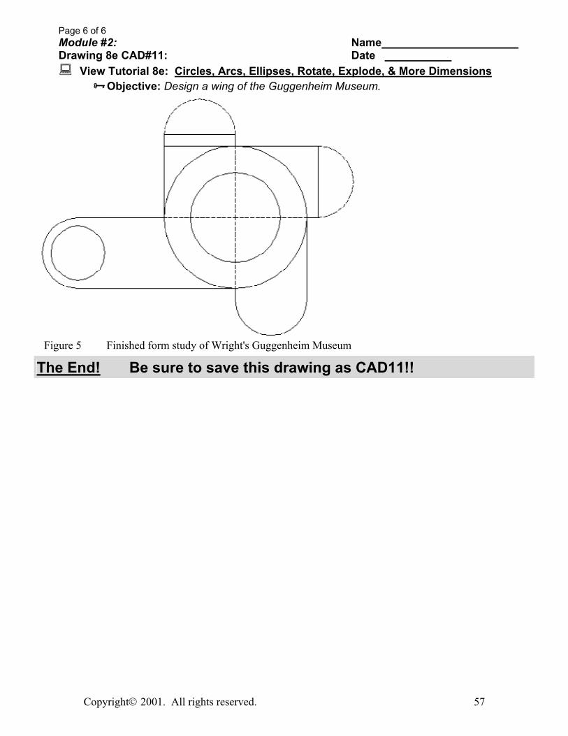
Select the 4 lines going to the circle center and the arcs in the "top- left" and "top-right" wings (see figure 5), then select Modify - Properties..., A dialog with the properties of the selected objects is displayed. Change the Linetype to HIDDEN and the Linetype Scale to 75 and dismiss the dialog.
The objects should be redrawn using dashed lines (see figure 5).
Page 6 of 6 Module #2: Name Drawing 8e CAD#11: Date
View Tutorial 8e: Circles, Arcs, Ellipses, Rotate, Explode, & More Dimensions Objective: Design a wing of the Guggenheim Museum.
Copyright 2001. All rights reserved. 57
Figure 5 Finished form study of Wright's Guggenheim Museum
The End! Be sure to save this drawing as CAD11!!