Embed Size (px)
Citation preview

THREE-POLE CONTACTORS• IEC Ith ratings in AC1 duty at �40°C: 16 to 1600A• IEC Ie ratings in AC3 440V duty: 6 to 630A• IEC Power ratings in AC3 400V duty:
2.2 to 335kW• UL/CSA ratings: 3 to 500HP at 480V and 600V• AC, AC/DC, DC and DC low-consumption coil.
Page 2-4 Page 2-8
FOUR-POLE CONTACTORS• IEC Ith ratings in AC1 duty at �40°C:
20 to 1600A• IEC Power ratings in AC1 400V duty:
14 to 950kW• UL/CSA general use: 16 to 1000A• AC, AC/DC, DC and DC low-consumption coil.
CONTACTORS FOR POWER FACTORCORRECTION• With limiting resistors included• IEC Power ratings at 400V: 7.5 to 75kvar• UL/CSA ratings: 9 to 80kvar at 480V;
10 to 100kvar at 600V• AC coil.
Page 2-14
FOUR-POLE CONTACTORS WITH 2NO+2NC MAIN POWER POLES• IEC Ith ratings in AC1 duty at �40°C:
20 to 115A• UL/CSA general use: 20 to 115A• AC, AC/DC, DC and DC low-consumption coil.
Page 2-12
FOUR-POLE CONTACTORS WITH 4 NC POLESFOR PHOTOVOLTAIC APPLICATIONS• IEC Ith ratings in AC1 duty at�40°C: 25 to 40A
• UL/CSA general use: 20 to 55A for 4NC types• Operational current up to 125A
(DC1 at �55°C with 4 NO poles in series) forphotovoltaic applications.
• AC, AC/DC, DC and DC low-consumption coil.
Page 2-13
CONTROL RELAYS• AC, DC and DC low-consumption coil• Screw or Faston termination• 4, 8 or 11 auxiliary contact composition.
Page 2-15
LOVATO Electric contactors are suitable fornew motors with high IE3 efficiency values

CONTACTORS 2Three-pole versions up to 630A in IEC AC3 dutyFour-pole versions up to 1600A in IEC AC1 dutyVersions for power factorcorrection up to 75kvar at 400VACFour-pole versions with 2NO+2NCor 4NC main polesVersions for photovoltaicapplicationVersions with AC, AC/DC or DCcontrolLow-consumption versions withDC control circuit for control relaysand 9-38A contactors in IEC AC3dutyExtensive choice of add-on blocksand accessoriesCertified by primary internationalauthorities.
SEC. - PAGEContactors
Three-pole ......................................................................................................................................................................... 2 - 4Four-pole .......................................................................................................................................................................... 2 - 8Four-pole with 2NO and 2NC poles or 4NC poles ................................................................................................................ 2 - 12Four-pole with 4NO poles for photovoltaic applications ............................................................................................................ 2 - 13For power factor correction ............................................................................................................................................... 2 - 14Control relays .................................................................................................................................................................... 2 - 15
Add-on blocks and accessoriesFor BG series mini-contactors ............................................................................................................................................ 2 - 16For BF series contactors .................................................................................................................................................... 2 - 18For B series contactors ...................................................................................................................................................... 2 - 26
Spare partsAC coils for BF series contactors ........................................................................................................................................ 2 - 28AC/DC and DC coils for BF series contactors ...................................................................................................................... 2 - 29AC/DC coils for B series contactors .................................................................................................................................... 2 - 30Main contacts for BF series contactors ............................................................................................................................... 2 - 31Main contacts and arc chutes for B series contactors ......................................................................................................... 2 - 31
Dimensions ................................................................................................................. 2 - 32Wiring diagrams ........................................................................................................... 2 - 44Technical characteristics ................................................................................................. 2 - 48
MO
TO
RC
ON
TR
OL
AN
DP
RO
TE
CT
ION

2
2-2
Contactors
3 poles 4 poles Ie (AC3) AC DC Ith (AC1) AC DCBG06 6A � � –– –– ––BG09 9A � � 20A � �
BGF09 9A � � 20A � �
BGP09 9A � � 20A � �
BG12 12A � � –– –– ––
BG seriesmini-contactors
3 poles Ie AC DC DC� AC/DC� AC3BF09 9A � � � ––BF12 12A � � � ––BF18 18A � � � ––BF25 25A � � � ––BF26 26A � � � ––BF32 32A � � � ––BF38 38A � � � ––BF40 40A � –– –– �BF50 50A � –– –– �BF65 65A � –– –– �BF80 80A � –– –– �BF95 95A � � –– ––BF110 110A � � –– ––
• Three-pole contactors, 9 to 110A IEC AC3 duty / 5 to 75HP 480V - 7.5 to 100HP 600V UL/CSA
• Four-pole contactors, 25 to 125A in AC1 duty• Power factor correction contactors, 7.5 to 75kvar at
400V IEC / 9 to 80kvar at 480V UL/CSA• Types with 2NO+2NC or 4NC main power poles• Types for photovoltaic applications• Highly conductive auxiliary contacts• Coils with AC or DC supply• Wide-range coils with electronic control for
contactors from 40 to 80A AC3• Low-consumption versions for control relays and 9-
38A contactors in IEC AC3 duty.
BF seriescontactors
4 poles Ith AC DC DC� AC/DC� AC1BF09 25A � � � ––BF12 28A � –– –– ––BF18 32A � � � ––BF26 45A � � � ––BF38 56A � � � ––BF40 70A � –– –– ––BF50 90A � –– –– ––BF65 100A � –– –– �BF80 115A � –– –– �� Low-consumption version.� Wide-range coil with electronic control.
3 poles 4 poles Ie (AC3) AC DC Ith (AC1) AC DCB115 110A � � 160A � �
B145 150A � � 250A � �
B180 185A � � 275A � �
B250 265A � � 350A � �
B310 320A � � 450A � �
B400 420A � � 550A � �
B500 520A � � 700A � �
B630 630A � � 800A � �
B630 1000 � � � 1000A � �
B1250 � � –– 1250A � ––B1600 � � –– 1600A � ––� For AC1 / general use duty only.
B seriescontactors
• Three-pole contactors, 110 to 630A IEC AC3 duty• Four-pole contactors, 160 to 1600A IEC AC1 duty• 100 to 500HP 600V UL/CSA• Coils with AC/DC supply• Screw termination.
• Three-pole mini-contactors, 6 to 12A IEC AC3duty / 3 to 7.5HP 480V - 3 to 10HP 600V UL/CSA
• Four-pole mini-contactors, 20A IEC AC1 duty• Versions with 2NO+2NC main power poles• Highly conductive auxiliary contacts• Coils with AC or DC supply• Low-consumption DC versions• Screw, faston and rear PCB solder pin
termination.
• Highly conductive auxiliary contacts with fourcontact points
• AC and DC versions of same size• Quick connect - snap on accessory mounting• Distinct contact status indication• Up to four auxiliary contacts can be mounted• Mechanical interlock only 5mm deep• Positive (force) guided contacts
(mechanically-linked per IEC)
• Highly conductive auxiliary contacts with fourcontact points
• Quick connect - snap on accessory mounting• Distinct contact status indication• Up to four auxiliary contacts can be mounted• Mechanical interlock only 5mm deep• Positive (force) guided contacts
(mechanically-linked per IEC)
• 3 frame sizes offering 11 different contactors• Coil operates indifferently on AC or DC supply voltage• Coil with low in-rush and holding• Coil removable without disconnecting power wiring• Red indicator when contactor is energised• Unique right-angle magnet design - limits contact
bounce• Safety feature prevents contactor to be energised
without arc chute in place and locked• Convertible auxiliary contact block (2NO + 1NC or
1NO + 2NC), maximum of 4 blocks per contactorfor a total of 12 contacts
• Contactor terminals with bolt, washer and nut • Simple horizontal or vertical interlock• Positive (force) guided contacts
(mechanically-linked per IEC)

SIDE ADD-ON FOURTHPOLEFor the 45A to 115A AC1ratings, a side-mountfourth power pole can besnapped on the three-polecontactor. This solution permits to optimiseinventory.
MECHANICAL INTERLOCKSmaller-size contactors, 9 to 25A in AC3, can bemechanically andelectrically interlocked withlarger-size contactors, 26 to 38A AC3.The BFX50 01 and BFX53 01mechanical interlock comprisestwo built-in NC auxiliary contacts tomake the electrical interlock aswell.
35MM IN RAIL MOUNTING ANDFIXING
Contactor mounting on and removalfrom a 35mm DIN rail are tool-lessoperations and are done by simplyapplying pressure on the contactor.
STARTER ASSEMBLY
The assembly and wiring ofelectromechanical starters isextremely fast and reliable. Versatileelectrical and mechanicalconnecting systems provide easyand foolproof assembly of compactstarters.
EFFORTLESS THERMALOVERLOAD RELAY LINK RF38 ANDRF82 TYPES
During the connection of thethermal overload relay to thecontactor, its auxiliary contact issimultaneously linked to thecontactor coil terminal rigidconnector.The complete overload relay fixingis obtained with one singleoperation and without otherconnections.
TERMINAL ADAPTABILITYTerminals are suitable for every typeof cable: flexible, rigid, according toAWG standards and interlocked withany type of cable terminal.For BF09...BF38 contactors, a singletype of screwdriver tightens thescrews for the power contacts,auxiliary contacts and coil.
SNAP-ON INSTALLATION
On the contactors, it’s quick and easyto fit and remove auxiliary contactsand accessories, without using tools;the same applies to replacing the coilin the AC BF09…BF38 contactors.
RUBBER PAD INSERT FOR NO DINRAIL SLIDING
A rubber insert prevents thecontactors from sliding on the35mm DIN rail even when out oftolerance or mounted vertically.
BREAKER-CONTACTORCONNECTIONS
The rigidconnectionsbetween breakerand contactorallow completecompact starters tobe created easily,quickly and withless space used inthe panel.
It is fitted on asingle DIN rail.
IP20 CONNECTION SECURITY
For BF09...BF38 contactors, the easyaccess and space for the terminals iscombined with IP20 protection,preventing accidental contact with liveparts.
DOUBLE LUG TERMINALS 40 to 80A AC3 contactors are
equipped with double lug terminals foreasy, functional access for powercables.
It is extremely simple to create star-delta starters, reversing switches,changeovers and arrange parallelsupply for several contactors.
4-TERMINAL COILConnecting cables can be coupled tothe coil both on the line and load ends of the contactor.
ELECTRONIC COILContactors from 40 to 80A AC3 can be equipped with AC/DC electronic coil with wide operating range.Example: single 100 to 250V AC/DC coil.
BUILT-IN SURGE SUPPRESSORBF series contactors up to 80A AC3 with voltages in DCor AC/DC already have a built-in surge suppressor.
LOW-CONSUMPTION COILSThe BF...L contactors feature a 2.4W low consumption.
This characteristic widely allows their direct control byPLC outputs.
45mm WIDE CONTACTORSRatings up to 38A - 18.5kW IEC AC3 /30HP UL - merely 45mm wide: exceptionalbenefit for electric panel dimensions.
55mm WIDE CONTACTORSUp to 80A in AC3 (45kW) with a width ofjust 55mm.
COILS WITH WIDEOPERATING RANGEBF...D contactors are equipped with a wideoperating range coil and are particularlyuseful in applications subject toconsiderable voltage variations, such as inelectric traction railway equipment.
2
2-3
ContactorsContactors BF00, BF09...BF80
THE IDEAL SOLUTION! A1 A2
A1 A2

2
2-4Add-on blocks / Accessoriespage 2-16 to 28
Spare partspages 2-29 to 31
Dimensionspages 2-32 to 38
Wiring diagrams page 2-44
Technical characteristics page 2-48 to 69
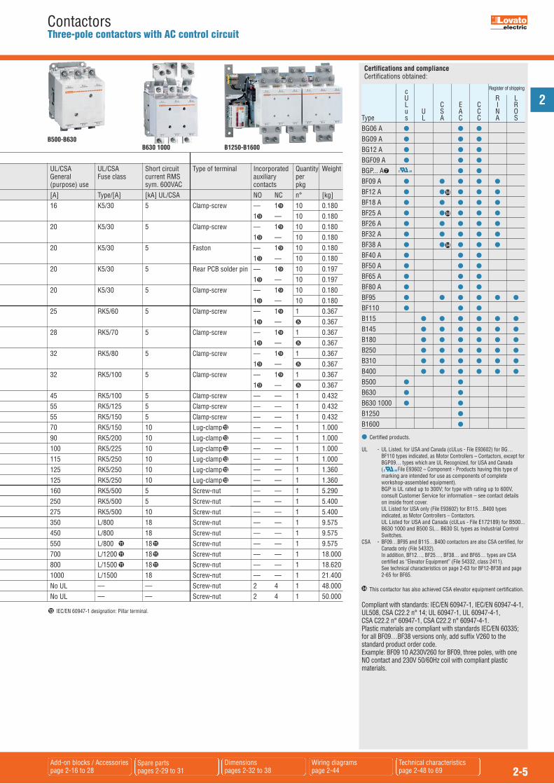
ContactorsThree-pole contactors with AC control circuit
BF95...BF110 B115...B180BG06 A...BG12 A BF26 A...BF38 A BF40 A...BF80 A B250...B400BF09 A...BF25 A
� Complete order code with coil voltage digit or with voltage digit followed by 60 (if 60Hz). Standard voltages are as follows: -- AC 50/60Hz 024 / 048 / 110 / 230 / 400V -- AC 60Hz 024 60 / 048 60 / 120 60 / 220 60 / 230 60 / 460 60 / 575 60 (V). Example: 11 BG06 10 A230 for mini-contactor BG06, three poles, with one NO contact and
230VAC 50/60Hz coil. 11 BG06 10 A460 60 for mini-contactor BG06 with one NO contact and 460VAC 60Hz
coil.� The coil of the contactor can be powered indifferently in AC or DC. Complete the order code only with the
digit of the coil voltage. Standard voltages are: -- AC/DC 24 / 48 / 60 / 110-125 (indicate 110) / 220-240 (indicate 220) / 380-415 (indicate 380) / 440-480V (indicate 440). Example: 11 B145 00 110 for contactor B145, three poles, without auxiliary contacts and with 110-125VAC/DC coil.
The 24VAC/DC voltage is not possible for B500-B630 1000 contactors.The 24VAC/DC voltage is not possible for B500-B630 1000 contactors.Other voltages available on request.
� If predisposed for mechanical latch (G495), the order code becomes 11 B…SL.00 � If already fitted with mechanical latch (G495), the order code becomes 11 B…L.00 � �.
� Indicate rated voltage of the mechanical latch, preceded by the letter C if in DC. Available voltages are: – AC 50/60Hz 48 / 110-125 indicate 110 / 220-240 indicate 220 / 380-415V indicate 380 – DC 48 / 110-125 indicate 110 / 220-240V indicate 220. Example: 11 B145L 00 110 220 for contactor B145 without auxiliary contacts, with
110-125VAC/DC coil and mechanical latch powered at 220-240VAC.� G495 mechanical latch cannot be mounted.� Complete the order code with the digit of the coil voltage. For 110-125VAC (50/60Hz) indicate 110 or
220-240VAC (50/60Hz) indicate 220. Example: 11 B1250 24 110 for contactor B1250, three poles, with 2NO+4NC auxiliary contacts and 110-
125VAC 50/60Hz coil. Maximum voltage is limited at 300V for UL. For certified type up to 600V, consult Customer Service for
information; see contact details on inside front cover. For voltages 024 / 230 / 400VAC 50-60Hz: 10 pieces/package. For all other voltages: 1 piece/package.� Highly conductive auxiliary contact.� For use at this other current value, a 16mm2 cable, headed with a fork terminal, must be used. No UL/CSA ratings; data given for indication and reference purposes only. Definite-purpose (DP) contactors are available. Consult Customer Service for information; see contact
details on inside front cover.
Order code IEC operating current Maximum IEC power at �55°C (AC3) Maximum UL/CSA horsepower ratings Ith (AC1) Ie (AC3) Single phase Three phase AC coil �40°C �55°C �70°C �440V at �55°C 230V 400V 415V 440V 500V 690V 1000V 120V 240V 200V 240V 480V 600V [A] [A] [A] [A] [A] [kW] [kW] [kW] [kW] [kW] [kW] [kW] [HP] [HP] [HP] [HP] [HP] [HP] 11 BG06 01 A� 16 14 12 6 1.5 2.2 2.4 2.5 3 3 –– 1/3 1 11/2 2 3 3 11 BG06 10 A� 11 BG09 01 A� 20 18 15 9 2.2 4 4.3 4.5 5 5 –– 1/2 11/2 2 3 5 5 11 BG09 10 A� 11 BGF09 01 A� 20 18 15 9 2.2 4 4.3 4.5 5 5 –– 1/2 11/2 2 3 5 5 11 BGF09 10 A�
11 BGP09 01 A� 20 18 15 9 2.2 4 4.3 4.5 5 –– –– 1/2 11/2 2 3 5 –– 11 BGP09 10 A� 11 BG12 01 A� 20 18 15 12 3.2 5.7 6.2 5.5 5 5 –– 1/2 11/2 3 3 71/2 10 11 BG12 10 A� BF09 01 A� 25 20 18 9 2.2 4.2 4.5 4.8 5.5 7.5 –– 3/4 2 3 3 5 71/2
BF09 10 A� BF12 01 A� 28 23 20 12 3.2 5.7 6.2 6.2 7.5 10 –– 1 2 5 5 71/2 10 BF12 10 A� BF18 01 A� 32 26 23 18 4 7.5 9 9 10 10 –– 1 3 5 5 10 15 BF18 10 A� BF25 01 A� 32 26 23 25 7 12.5 13.4 13.4 15 11 –– 2 3 71/2 71/2 15 15 BF25 10 A� BF26 00 A� 45 36 32 26 7.3 13 14 14 15.6 18.5 –– 2 5 71/2 71/2 15 20 BF32 00 A� 56 45 40 32 8.8 16 17 17 20 22 –– 3 71/2 10 10 20 25 BF38 00 A� 56 (60�) 45 (48�) 40 (42�) 38 11 18.5 18.5 18.5 20 22 –– 3 71/2 10 15 30 30 BF40 00A � 70 60 50 40 11 18.5 22 22 22 30 18 3 71/2 10 15 30 40 BF50 00A � 90 75 60 50 15 22 30 30 30 37 22 5 10 10 15 30 40 BF65 00A � 100 80 65 65 18.5 30 37 37 37 45 30 –– –– 20 25 50 60 BF80 00A � 115 95 75 80 22 45 45 45 55 75 37 –– –– 25 30 60 75 11 BF95 00� 125 100 80 95 27.6 50 55 55 56 74 45 –– –– 30 30 60 75 11 BF110 00� 125 100 80 110 33 61 66 70 59 80 45 –– –– 30 40 75 100 11 B115 00�� 160 150 110 110 33 61 66 70 80 100 63 –– –– 30 40 75 100 11 B145 00�� 250 235 190 150 46 80 88 93 100 120 75 –– –– 50 50 100 125 11 B180 00�� 275 250 200 185 57 100 108 115 123 144 103 –– –– 60 75 150 150 11 B250 00�� 350 300 250 265 83 140 155 164 176 212 156 –– –– 75 100 200 250 11 B310 00�� 450 370 300 320 100 170 188 200 213 256 180 –– –– 100 125 250 300 11 B400 00�� 550 430 360 420 130 225 247 263 271 352 208 –– –– 125 150 350 400 11 B500 00�� 700 550 500 520 156 290 306 328 367 416 312 –– –– 150 200 400 450 11 B630 00�� 800 640 540 630 198 335 368 368 368 440 368 –– –– 200 250 500 500 11 B630 1000 00�� 1000 850 700 –– For AC1/Resistive duty only, see page 2-8. –– –– –– –– –– –– 11 B1250 24�� 1250 1050 880 –– For AC1/Resistive duty only, see page 2-8. No UL –– –– –– –– –– 11 B1600 24�� 1600 1360 1120 –– For AC1/Resistive duty only, see page 2-8. No UL –– –– –– –– ––
Three-phase motor control in AC3 duty UL/CSA details
1112
11 11 11 11
11 11 11 11
12
12
12
12
12
12
12
12
12
12
12
12
2
2-5Add-on blocks / Accessoriespage 2-16 to 28
Spare partspages 2-29 to 31
Dimensionspages 2-32 to 38
Wiring diagramspage 2-44
Technical characteristics page 2-48 to 69
ContactorsThree-pole contactors with AC control circuit
B500-B630B1250-B1600B630 1000
c Register of shipping
U R L L C E C I R u U S A C N OType s L A C C A SBG06 A � � �
BG09 A � � �
BG12 A � � �
BGF09 A � � �
BGP... A � �
BF09 A � � � � �
BF12 A � � � � �
BF18 A � � � � �
BF25 A � � � � �
BF26 A � � � � �
BF32 A � � � � �
BF38 A � � � � �
BF40 A � � � BF50 A � � � BF65 A � � � BF80 A � � �
BF95 � � � � � �BF110 � � �
B115 � � � � � �B145 � � � � � �B180 � � � � � �B250 � � � � � �B310 � � � � � �
B400 � � � � � �B500 � � B630 � � B630 1000 � � B1250 �B1600 �
Certifications and complianceCertifications obtained:
14
14
14
� Certified products.
UL - UL Listed, for USA and Canada (cULus - File E93602) for BG…BF110 types indicated, as Motor Controllers – Contactors, except forBGP09… types which are UL Recognized, for USA and Canada ( File E93602 – Component - Products having this type ofmarking are intended for use as components of completeworkshop-assembled equipment).
BGP is UL rated up to 300V; for type with rating up to 600V,consult Customer Service for information – see contact detailson inside front cover.
UL Listed for USA only (File E93602) for B115…B400 typesindicated, as Motor Controllers – Contactors.
UL Listed for USA and Canada (cULus - File E172189) for B500...B630 1000 and B500 SL... B630 SL types as Industrial ControlSwitches.
CSA - BF09…BF95 and B115…B400 contactors are also CSA certified, forCanada only (File 54332).
In addition, BF12…, BF25…, BF38… and BF65… types are CSAcertified as “Elevator Equipment” (File 54332, class 2411). See technical characteristics on page 2-63 for BF12-BF38 and page2-65 for BF65.
This contactor has also achieved CSA elevator equipment certification.
Compliant with standards: IEC/EN 60947-1, IEC/EN 60947-4-1,UL508, CSA C22.2 n° 14; UL 60947-1, UL 60947-4-1, CSA C22.2 n° 60947-1, CSA C22.2 n° 60947-4-1.Plastic materials are compliant with standards IEC/EN 60335;for all BF09…BF38 versions only, add suffix V260 to thestandard product order code.Example: BF09 10 A230V260 for BF09, three poles, with oneNO contact and 230V 50/60Hz coil with compliant plasticmaterials.
14
� IEC/EN 60947-1 designation: Pillar terminal.
UL/CSA UL/CSA Short circuit Type of terminal Incorporated Quantity WeightGeneral Fuse class current RMS auxiliary per(purpose) use sym. 600VAC contacts pkg [A] Type/[A] [kA] UL/CSA NO NC n° [kg]16 K5/30 5 Clamp-screw –– 1� 10 0.180
1� –– 10 0.18020 K5/30 5 Clamp-screw –– 1� 10 0.180
1� –– 10 0.18020 K5/30 5 Faston –– 1� 10 0.180
1� –– 10 0.18020 K5/30 5 Rear PCB solder pin –– 1� 10 0.197
1� –– 10 0.19720 K5/30 5 Clamp-screw –– 1� 10 0.180
1� –– 10 0.18025 RK5/60 5 Clamp-screw –– 1� 1 0.367
1� –– 0.36728 RK5/70 5 Clamp-screw –– 1� 1 0.367
1� –– 0.36732 RK5/80 5 Clamp-screw –– 1� 1 0.367
1� –– 0.36732 RK5/100 5 Clamp-screw –– 1� 1 0.367
1� –– 0.36745 RK5/100 5 Clamp-screw –– –– 1 0.43255 RK5/125 5 Clamp-screw –– –– 1 0.43255 RK5/150 5 Clamp-screw –– –– 1 0.43270 RK5/150 10 Lug-clamp –– –– 1 1.00090 RK5/200 10 Lug-clamp –– –– 1 1.000100 RK5/225 10 Lug-clamp –– –– 1 1.000115 RK5/250 10 Lug-clamp –– –– 1 1.000125 RK5/250 10 Lug-clamp –– –– 1 1.360125 RK5/250 10 Lug-clamp –– –– 1 1.360160 RK5/500 5 Screw-nut –– –– 1 5.290250 RK5/500 5 Screw-nut –– –– 1 5.400275 RK5/500 10 Screw-nut –– –– 1 5.400350 L/800 18 Screw-nut –– –– 1 9.575450 L/800 18 Screw-nut –– –– 1 9.575550 L/800 18 Screw-nut –– –– 1 9.575700 L/1200 18 Screw-nut –– –– 1 18.000800 L/1500 18 Screw-nut –– –– 1 18.6201000 L/1500 18 Screw-nut –– –– 1 21.400No UL –– –– Screw-nut 2 4 1 48.000No UL –– –– Screw-nut 2 4 1 50.000
11
11
11
11
11
11
13
13
13
13
13
13
13
2
2-6Add-on blocks / Accessoriespage 2-16 to 28
Spare partspages 2-29 to 31
Dimensionspages 2-32 to 38
Wiring diagrams page 2-44
Technical characteristics pages 2-48 to 69
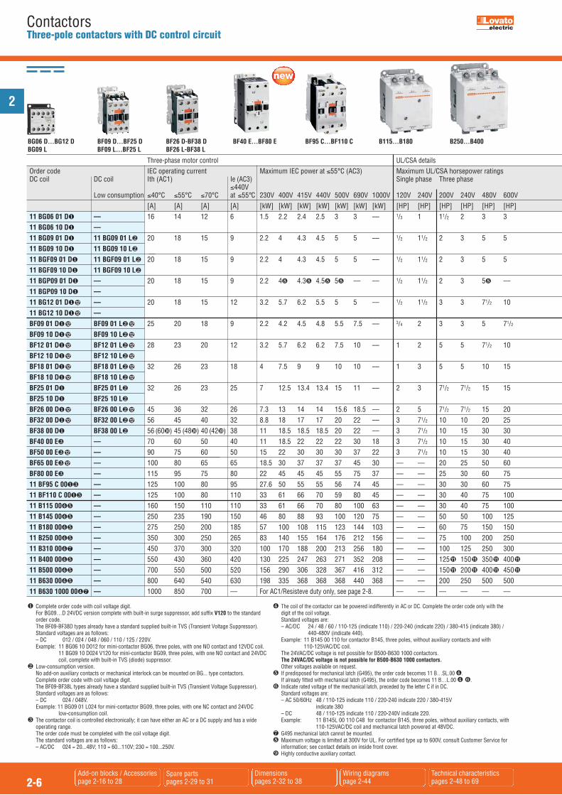
ContactorsThree-pole contactors with DC control circuit
BF26 D-BF38 DBF26 L-BF38 L
BF95 C...BF110 C B115...B180BG06 D...BG12 DBG09 L
BF40 E...BF80 E B250...B400BF09 D...BF25 DBF09 L...BF25 L
Order code IEC operating current Maximum IEC power at �55°C (AC3) Maximum UL/CSA horsepower ratings DC coil DC coil Ith (AC1) Ie (AC3) Single phase Three phase �440V Low consumption �40°C �55°C �70°C at �55°C 230V 400V 415V 440V 500V 690V 1000V 120V 240V 200V 240V 480V 600V [A] [A] [A] [A] [kW] [kW] [kW] [kW] [kW] [kW] [kW] [HP] [HP] [HP] [HP] [HP] [HP] 11 BG06 01 D� –– 16 14 12 6 1.5 2.2 2.4 2.5 3 3 –– 1/3 1 11/2 2 3 3 11 BG06 10 D� –– 11 BG09 01 D� 11 BG09 01 L� 20 18 15 9 2.2 4 4.3 4.5 5 5 –– 1/2 11/2 2 3 5 5 11 BG09 10 D� 11 BG09 10 L� 11 BGF09 01 D� 11 BGF09 01 L� 20 18 15 9 2.2 4 4.3 4.5 5 5 –– 1/2 11/2 2 3 5 5 11 BGF09 10 D� 11 BGF09 10 L�
11 BGP09 01 D� –– 20 18 15 9 2.2 4 4.3 4.5 5 –– –– 1/2 11/2 2 3 5 –– 11 BGP09 10 D� –– 11 BG12 01 D� –– 20 18 15 12 3.2 5.7 6.2 5.5 5 5 –– 1/2 11/2 3 3 71/2 10 11 BG12 10 D� –– BF09 01 D� BF09 01 L� 25 20 18 9 2.2 4.2 4.5 4.8 5.5 7.5 –– 3/4 2 3 3 5 71/2 BF09 10 D� BF09 10 L� BF12 01 D� BF12 01 L� 28 23 20 12 3.2 5.7 6.2 6.2 7.5 10 –– 1 2 5 5 71/2 10 BF12 10 D� BF12 10 L� BF18 01 D� BF18 01 L� 32 26 23 18 4 7.5 9 9 10 10 –– 1 3 5 5 10 15 BF18 10 D� BF18 10 L� BF25 01 D� BF25 01 L� 32 26 23 25 7 12.5 13.4 13.4 15 11 –– 2 3 71/2 71/2 15 15 BF25 10 D� BF25 10 L� BF26 00 D� BF26 00 L� 45 36 32 26 7.3 13 14 14 15.6 18.5 –– 2 5 71/2 71/2 15 20 BF32 00 D� BF32 00 L� 56 45 40 32 8.8 18 17 17 20 22 –– 3 71/2 10 10 20 25 BF38 00 D� BF38 00 L� 56 (60�) 45 (48�) 40 (42�) 38 11 18.5 18.5 18.5 20 22 –– 3 71/2 10 15 30 30 BF40 00 E� –– 70 60 50 40 11 18.5 22 22 22 30 18 3 71/2 10 15 30 40 BF50 00 E� –– 90 75 60 50 15 22 30 30 30 37 22 3 71/2 10 15 30 40 BF65 00 E� –– 100 80 65 65 18.5 30 37 37 37 45 30 –– –– 20 25 50 60 BF80 00 E� –– 115 95 75 80 22 45 45 45 55 75 37 –– –– 25 30 60 75 11 BF95 C 00�� –– 125 100 80 95 27.6 50 55 55 56 74 45 –– –– 30 30 60 75 11 BF110 C 00�� –– 125 100 80 110 33 61 66 70 59 80 45 –– –– 30 40 75 100 11 B115 00�� –– 160 150 110 110 33 61 66 70 80 100 63 –– –– 30 40 75 100 11 B145 00�� –– 250 235 190 150 46 80 88 93 100 120 75 –– –– 50 50 100 125 11 B180 00�� –– 275 250 200 185 57 100 108 115 123 144 103 –– –– 60 75 150 150 11 B250 00�� –– 350 300 250 265 83 140 155 164 176 212 156 –– –– 75 100 200 250 11 B310 00� –– 450 370 300 320 100 170 188 200 213 256 180 –– –– 100 125 250 300 11 B400 00�� –– 550 430 360 420 130 225 247 263 271 352 208 –– –– 125 150 350 400 11 B500 00�� –– 700 550 500 520 156 290 306 328 367 416 312 –– –– 150 200 400 450 11 B630 00�� –– 800 640 540 630 198 335 368 368 368 440 368 –– –– 200 250 500 500 11 B630 1000 00� –– 1000 850 700 –– For AC1/Resisteve duty only, see page 2-8. –– –– –– –– –– ––
Three-phase motor control
� Complete order code with coil voltage digit. For BG09…D 24VDC version complete with built-in surge suppressor, add suffix V120 to the standard
order code. The BF09-BF38D types already have a standard supplied built-in TVS (Transient Voltage Suppressor). Standard voltages are as follows: – DC 012 / 024 / 048 / 060 / 110 / 125 / 220V. Example: 11 BG06 10 D012 for mini-contactor BG06, three poles, with one NO contact and 12VDC coil. 11 BG09 10 D024 V120 for mini-contactor BG09, three poles, with one NO contact and 24VDC coil, complete with built-in TVS (diode) suppressor.� Low-consumption version. No add-on auxiliary contacts or mechanical interlock can be mounted on BG... type contactors. Complete order code with coil voltage digit. The BF09-BF38L types already have a standard supplied built-in TVS (Transient Voltage Suppressor). Standard voltages are as follows: – DC 024 / 048V. Example: 11 BG09 01 L024 for mini-contactor BG09, three poles, with one NC contact and 24VDC
low-consumption coil.� The contactor coil is controlled electronically; it can have either an AC or a DC supply and has a wide
operating range. The order code must be completed with the coil voltage digit. The standard voltages are as follows: – AC/DC 024 = 20...48V; 110 = 60...110V; 230 = 100...250V.
� The coil of the contactor can be powered indifferently in AC or DC. Complete the order code only with thedigit of the coil voltage.
Standard voltages are: – AC/DC 24 / 48 / 60 / 110-125 (indicate 110) / 220-240 (indicate 220) / 380-415 (indicate 380) / 440-480V (indicate 440). Example: 11 B145 00 110 for contactor B145, three poles, without auxiliary contacts and with
110-125VAC/DC coil.The 24VAC/DC voltage is not possible for B500-B630 1000 contactors.The 24VAC/DC voltage is not possible for B500-B630 1000 contactors.Other voltages available on request.
� If predisposed for mechanical latch (G495), the order code becomes 11 B…SL.00 �. If already fitted with mechanical latch (G495), the order code becomes 11 B…L.00 � �.� Indicate rated voltage of the mechanical latch, preceded by the letter C if in DC. Standard voltages are: – AC 50/60Hz 48 / 110-125 indicate 110 / 220-240 indicate 220 / 380-415V
indicate 380 – DC 48 / 110-125 indicate 110 / 220-240V indicate 220. Example: 11 B145L 00 110 C48 for contactor B145, three poles, without auxiliary contacts, with
110-125VAC/DC coil and mechanical latch powered at 48VDC. G495 mechanical latch cannot be mounted. Maximum voltage is limited at 300V for UL. For certified type up to 600V, consult Customer Service for
information; see contact details on inside front cover.� Highly conductive auxiliary contact.
11
11
11
11
11
11
11
11
12
12
12
12
12
12
12
12
12
12
12
12
12
12
12
12
12
12
12
12
UL/CSA details

2
2-7Add-on blocks / Accessoriespage 2-16 to 28
Spare partspages 2-29 to 31
Dimensionspages 2-32 to 38
Wiring diagramspage 2-44
Technical characteristics page 2-48 to 69
ContactorsThree-pole contactors with DC control circuit
B500-B630B630 1000
c U R L C E C I u U S A C NType s L A C C ABG06 D � � �
BG09 D � � �
BG12 D � � �
BGF09 D � � �
BGP09 D � �
BF09 D - BF09 L � � � � �
BF12 D - BF12 L � � � � �
BF18 D - BF18 L � � � � �
BF25 D - BF25 L � � � � �
BF26 D - BF26 L � � � � �
BF32 D - BF32 L � � � � �
BF38 D - BF38 L � � � � �
BF40 E � � �
BF50 E � � �
BF65 E � � �
BF80 E � � �
BF95 C � � � � �
BF110 C � � �
B115 � � � � �B145 � � � � �B180 � � � � �B250 � � � � �B310 � � � � �
B400 � � � � �B500 � � B630 � � �B630 1000 � �
Certifications and complianceCertifications obtained:
14
14
14
� Certified products.
UL - UL Listed, for USA and Canada (cULus File E93602) for BG…BF110types indicated, as Motor Controllers – Contactors, except forBGP09… types which are UL Recognized, for USA and Canada ( File E93602 – Component). Products having this type ofmarking are intended for use as components of completeworkshop-assembled equipment.
BGP is UL rated up to 300V; for type with rating up to 600V,consult Customer Service for information – see contact detailson inside front cover.
UL Listed for USA only (File E93602) for B115…B400 typesindicated, as Motor Controllers – Contactors.
UL Listed for USA and Canada (cULus - File E172189) for B500...B630 1000 and B500 SL... B630 SL types as Industrial ControlSwitches.
CSA - BF09…BF95 and B115…B400 contactors are also CSA certified, forCanada only (File 54332).
In addition, BF12…, BF25…, BF38… and BF65… types are CSAcertified as “Elevator Equipment” (File 54332, class 2411). See technical characteristics on page 2-63 for BF12-BF38 and page2-65 for BF65.
This contactor has also achieved CSA elevator equipment certification.
Compliant with standards: IEC/EN 60947-1, IEC/EN 60947-4-1,UL508, CSA C22.2 n° 14; UL 60947-1, UL 60947-4-1, CSA C22.2 n° 60947-1, CSA C22.2 n° 60947-4-1.Plastic materials are compliant with standards IEC/EN 60335;for all BF09…BF38 versions only, add suffix V260 to thestandard product order code.Example: BF09 10 D024 V260 for BF09, three poles, with oneNO contact and 24VDC coil with compliant plastic materials.
14
UL/CSA UL/CSA Short circuit Type of terminal Incorporated Quantity Weight General Fuse class current RMS auxiliary per (purpose) use sym. 600VAC contacts pkg [A] Type/[A] [kA] UL/CSA NO NC n° [kg] 16 K5/30 5 Clamp-screw –– 1� 10 0.214 1� –– 10 0.214 20 K5/30 5 Clamp-screw –– 1� 10 0.214 1� –– 10 0.214 20 K5/30 5 Faston –– 1� 10 0.210 1� –– 10 0.210 20 K5/30 5 Rear PCB solder pin –– 1� 10 0.240 1� –– 10 0.240 20 K5/30 5 Clamp-screw –– 1� 10 0.214 1� –– 10 0.214 25 RK5/60 5 Clamp-screw –– 1� 1 0.494 1 –– 1 0.494 28 RK5/70 5 Clamp-screw –– 1� 1 0.494 1 –– 1 0.494 32 RK5/80 5 Clamp-screw –– 1� 1 0.494 1 –– 1 0.494 32 RK5/100 5 Clamp-screw –– 1� 1 0.494 1 –– 1 0.494 45 RK5/100 5 Clamp-screw –– –– 1 0.559 55 RK5/125 5 Clamp-screw –– –– 1 0.559 55 RK5/150 5 Clamp-screw –– –– 1 0.559 70 RK5/150 10 Lug-clamp –– –– 1 1.050 90 RK5/200 10 Lug-clamp –– –– 1 1.050 100 RK5/225 10 Lug-clamp –– –– 1 1.050 115 RK5/250 10 Lug-clamp –– –– 1 1.050 125 RK5/250 10 Lug-clamp –– –– 1 1.895 125 RK5/250 10 Lug-clamp –– –– 1 1.895 160 RK5/500 10 Screw-nut –– –– 1 5.290 250 RK5/500 10 Screw-nut –– –– 1 5.400 275 RK5/500 10 Screw-nut –– –– 1 5.400 350 L/800 18 Screw-nut –– –– 1 9.635 450 L/800 18 Screw-nut –– –– 1 9.635 500 L/800 18 Screw-nut –– –– 1 9.635 700 L/1200 18 Screw-nut –– –– 1 18.060 800 L/1500 18 Screw-nut –– –– 1 18.620 1000 L/1500 18 Screw-nut –– –– 1 21.400
13
13
11
11
11
11
11
1113
13
13
13
13
13
13
� For use at this other current value, a 16mm2 cable, headed with a fork terminal, must be used. No UL/CSA ratings; data given for indication and reference purposes only. Definite-purpose (DP) contactors are available. Consult Customer Service for information; see contact
details on inside front cover. IEC/EN 60947-1 designation: Pillar terminal.13
1112

2
2-8Add-on blocks / Accessoriespage 2-16 to 28
Spare partspages 2-29 to 31
Dimensionspages 2-32 to 38
Wiring diagrams page 2-45
Technical characteristics pages 2-48 to 69
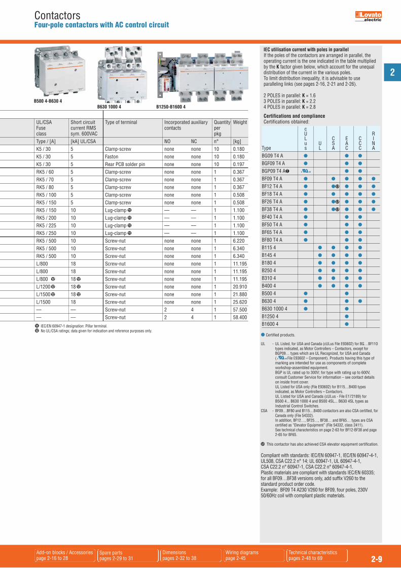
ContactorsFour-pole contactors with AC control circuit
BG09 T4 A BF40 T4 A...BF80 T4 ABF09A T4 A...BF18 T4 A B115 4...B180 4 B250 4...B400 4BF26 T4 A...BF38 T4 A
� Complete order code with coil voltage digit or voltage digit followed by 60 if 60Hz. Standard voltages are as follows: -- AC 50/60Hz 024 / 048 / 110 / 230 / 400V -- AC 60Hz 024 60 / 048 60 / 120 60 / 220 60 / 230 60 / 460 60 / 575 60 (V). Example: 11 BG09 T4 A230 for mini-contactor BG09, four poles, with 230VAC 50/60Hz coil. 11 BG09 T4 A460 60 for mini-contactor BG09, four poles, with 460VAC 60Hz coil.� The coil of the contactor can be powered indifferently in AC or DC. Complete the order code only with the
digit of the coil voltage. Standard voltages are: -- AC/DC 24 / 48 / 60 / 110-125 (indicate 110) / 220-240 (indicate 220) / 380-415 (indicate 380) / 440-480V (indicate 440). Example: 11 B145 4 00 110 for contactor B145, four poles, without auxiliary contacts and with
110-125VAC/DC coil.The 24VAC/DC voltage is not possible for B500-B630 1000 contactors.The 24VAC/DC voltage is not possible for B500-B630 1000 contactors.Other voltages available on request.
� If predisposed for mechanical latch (G495), the order code becomes 11 B…4SL 00 �. If already fitted with mechanical latch (G495), the order code becomes 11 B…4L.00 � �.� Indicate rated voltage of the mechanical latch, preceded by the letter C if in DC. Standard voltages are: -- AC 50/60Hz 48 / 110-125 indicate 110 / 220-240 indicate 220 / 380-415V indicate 380 -- DC 48 / 110-125 indicate 110 / 220-240V indicate 220. Example: 11 B145 4L 00 110 C220 for contactor B145, four poles, without auxiliary contacts, with
110-125VAC/DC coil and mechanical latch powered at 220-240VDC.
� G495 mechanical latch cannot be mounted.� Complete the order code with the digit of the coil voltage. For 110-125VAC 50/60 Hz indicate 110 or 220-240VAC 50/60 Hz indicate 220. Example: 11 B1250 4 24 110 for contactor B1250, four poles, with 2NO+4NC auxiliary contacts and
110-125VAC/DC 50/60Hz coil. Maximum voltage is limited at 300V for UL. For certified type up to 600V. Consult Customer Service for
information; see contact details on inside front cover. Whenever the BF26 T4 or BF38 T4 types need to be mechanically interlocked with either the BFX50 00 or
BFX50 01, the add-on fourth pole of one of the contactors needs to be removed from the right side andfitted on the left side.
� For use at this other current value, a 16mm2 cable, headed with a fork terminal, must be used.� Definite-purpose (DP) contactors are available. Consult Customer Service for information; see contact
details on inside front cover.
Order code IEC operating current Maximum IEC power at �40°C (AC1) UL/CSA Ith (AC1) General AC coil �40°C �55°C �70°C 230V 400V 415V 440V 500V 690V 1000V (purpose) use [A] [A] [A] [kW] [kW] [kW] [kW] [kW] [kW] [kW] [A] 11 BG09 T4 A�� 20 18 15 8 14 14 15 16 22 –– 20 11 BGF09 T4 A� 20 18 15 8 14 14 15 16 22 –– 20 11 BGP09 T4 A� 20 18 15 8 14 14 15 16 –– –– 20 BF09 T4 A�� 25 20 18 9.5 16 17 18 21 27 –– 25 BF12 T4 A�� 28 23 20 10 18 19 20 23 32 –– 28 BF18 T4 A�� 32 26 23 12 21 22 23 26 36 –– 32 BF26 T4 A�� 45 36 32 17 30 31 33 37 51 –– 45 BF38 T4 A� 56 (60�) 45 (48�) 40 (42�) 21 36 38 40 45 62 –– 55 BF40 T4 A� 70 60 50 26 46 48 51 58 79 115 70 BF50 T4 A� 90 75 60 34 59 61 65 74 102 148 90 BF65 T4 A� 100 80 65 38 65 68 72 82 114 165 100 BF80 T4 A� 115 95 75 43 76 79 83 95 120 185 115 11 B115 4 00�� 160 150 110 57 98 107 115 129 173 250 160 11 B145 4 00�� 250 235 190 91 150 162 180 196 270 390 250 11 B180 4 00�� 275 250 200 95 160 177 200 213 298 430 275 11 B250 4 00�� 350 300 250 124 214 234 255 282 380 560 350 11 B310 4 00�� 450 370 300 158 270 293 325 350 488 700 450 11 B400 4 00�� 550 430 360 200 345 377 400 452 598 870 550 11 B500 4 00�� 700 550 500 252 438 478 500 575 755 1100 700 11 B630 4 00�� 800 640 540 288 500 545 580 655 860 1250 800 11 B630 1000 4 00�� 1000 850 700 350 600 630 725 750 1000 1600 1000 11 B1250 4 24�� 1250 1050 880 480 830 900 905 1100 1450 2000 No UL/CSA 11 B1600 4 24�� 1600 1360 1120 550 950 1000 1160 1200 1650 2500 No UL/CSA
Resistive load control UL/CSA details
2
2-9Add-on blocks / Accessoriespage 2-16 to 28
Spare partspages 2-29 to 31
Dimensionspages 2-32 to 38
Wiring diagrams page 2-45
Technical characteristics pages 2-48 to 69
ContactorsFour-pole contactors with AC control circuit
Certifications and complianceCertifications obtained:
B630 1000 4B500 4-B630 4
B1250-B1600 4
IEC utilisation current with poles in parallelIf the poles of the contactors are arranged in parallel, theoperating current is the one indicated in the table multipliedby the K factor given below, which account for the unequaldistribution of the current in the various poles.To limit distribution inequality, it is advisable to useparalleling links (see pages 2-16, 2-21 and 2-26).
2 POLES in parallel: K = 1.63 POLES in parallel: K = 2.24 POLES in parallel: K = 2.8
c U R L C E C I u U S A C NType s L A C C ABG09 T4 A � � �
BGF09 T4 A � � �
BGP09 T4 A � �
BF09 T4 A � � � � �
BF12 T4 A � � � � �
BF18 T4 A � � � � �
BF26 T4 A � � � � �
BF38 T4 A � � � � �
BF40 T4 A � � �
BF50 T4 A � � �
BF65 T4 A � � �
BF80 T4 A � � �
B115 4 � � � �
B145 4 � � � �
B180 4 � � � �
B250 4 � � � �
B310 4 � � � �
B400 4 � � � �
B500 4 � �B630 4 � � �
B630 1000 4 � �B1250 4 �B1600 4 �
� Certified products.
UL - UL Listed, for USA and Canada (cULus File E93602) for BG…BF110types indicated, as Motor Controllers – Contactors, except forBGP09… types which are UL Recognized, for USA and Canada ( File E93602 – Component). Products having this type ofmarking are intended for use as components of completeworkshop-assembled equipment.
BGP is UL rated up to 300V; for type with rating up to 600V,consult Customer Service for information – see contact detailson inside front cover.
UL Listed for USA only (File E93602) for B115…B400 typesindicated, as Motor Controllers – Contactors.
UL Listed for USA and Canada (cULus - File E172189) for B500 4... B630 1000 4 and B500 4SL... B630 4SL types asIndustrial Control Switches.
CSA - BF09…BF80 and B115…B400 contactors are also CSA certified, forCanada only (File 54332).
In addition, BF12…, BF25…, BF38… and BF65… types are CSAcertified as “Elevator Equipment” (File 54332, class 2411).
See technical characteristics on page 2-63 for BF12-BF38 and page2-65 for BF65.
This contactor has also achieved CSA elevator equipment certification.
Compliant with standards: IEC/EN 60947-1, IEC/EN 60947-4-1,UL508, CSA C22.2 n° 14; UL 60947-1, UL 60947-4-1, CSA C22.2 n° 60947-1, CSA C22.2 n° 60947-4-1.Plastic materials are compliant with standards IEC/EN 60335;for all BF09…BF38 versions only, add suffix V260 to thestandard product order code.Example: BF09 T4 A230 V260 for BF09, four poles, 230V50/60Hz coil with compliant plastic materials.
UL/CSA Short circuit Type of terminal Incorporated auxiliary Quantity WeightFuse current RMS contacts per class sym. 600VAC pkg Type / [A] [kA] UL/CSA NO NC n° [kg]K5 / 30 5 Clamp-screw none none 10 0.180K5 / 30 5 Faston none none 10 0.180K5 / 30 5 Rear PCB solder pin none none 10 0.197RK5 / 60 5 Clamp-screw none none 1 0.367RK5 / 70 5 Clamp-screw none none 1 0.367RK5 / 80 5 Clamp-screw none none 1 0.367RK5 / 100 5 Clamp-screw none none 1 0.508RK5 / 150 5 Clamp-screw none none 1 0.508RK5 / 150 10 Lug-clamp –– –– 1 1.100RK5 / 200 10 Lug-clamp –– –– 1 1.100RK5 / 225 10 Lug-clamp –– –– 1 1.100RK5 / 250 10 Lug-clamp –– –– 1 1.100RK5 / 500 10 Screw-nut none none 1 6.220RK5 / 500 10 Screw-nut none none 1 6.340RK5 / 500 10 Screw-nut none none 1 6.340L/800 18 Screw-nut none none 1 11.195L/800 18 Screw-nut none none 1 11.195L/800 18 Screw-nut none none 1 11.195L/1200 18 Screw-nut none none 1 20.910L/1500 18 Screw-nut none none 1 21.880L/1500 18 Screw-nut none none 1 25.620–– –– Screw-nut 2 4 1 57.500–– –– Screw-nut 2 4 1 58.400
12
12
12
12
12 12
11
11
11
11
� IEC/EN 60947-1 designation: Pillar terminal.� No UL/CSA ratings; data given for indication and reference purposes only.1112
13
13
13
13
2
2-10Add-on blocks / Accessoriespage 2-16 to 28
Spare partspages 2-29 to 31
Dimensionspages 2-32 to 38
Wiring diagrams page 2-45
Technical characteristics pages 2-48 to 69
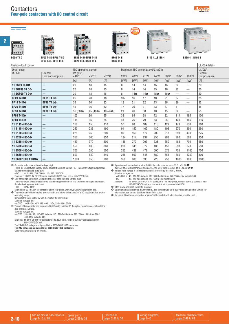
ContactorsFour-pole contactors with DC control circuit
BG09 T4 D BF26 T4 D-BF38 T4 DBF26 T4 L-BF38 T4 L
BF65 T4 EBF80 T4 E
BF09 T4 D-BF18 T4 DBF09 T4 L-BF18 T4 L
B115 4...B180 4 B250 4...B400 4
� Complete order code with coil voltage digit. The BF09-BF38D types already have a standard supplied built-in TVS (Transient Voltage Suppressor).Standard voltages are as follows:
– DC 012 / 024 / 048 / 060 / 110 / 125 / 220VDC. Example: 11 BG09 T4 D012 for mini-contactor BG09, four poles, with 12VDC coil.� Low consumption version. Complete the order code with coil voltage digit.
The BF09-BF38L types already have a standard supplied built-in TVS (Transient Voltage Suppressor).Standard voltages are as follows:
– DC 024 / 048V Example: BF09 T4 L024 for contactor BF09, four poles, with 24VDC low-consumption coil.� The contactor coil is controlled electronically; it can have either an AC or a DC supply and has a wide
operating range. Complete the order code only with the digit of the coil voltage. Standard voltages are: – AC/DC 024 = 20...48V; 110 = 60...110V; 230 = 100...250V.� The coil of the contactor can be powered indifferently in AC or DC. Complete the order code only with the
digit of the coil voltage. Standard voltages are: -- AC/DC 24 / 48 / 60 / 110-125 indicate 110 / 220-240 indicate 220 / 380-415 indicate 380 / 440-480V indicate 440. Example: 11 B145 00 110 for contactor B145, four poles, without auxiliary contacts and with
110-125VAC/DC coil. The 24VAC/DC voltage is not possible for B500-B630 1000 contactors. The 24V voltage is not possible for B500-B630 1000 contactors. Other voltages available on request.
� If predisposed for mechanical latch (G495), the order code becomes 11 B…4SL 00 �. If already fitted with mechanical latch (G495), the order code becomes 11 B…4L.00 � �.� Indicate rated voltage of the mechanical latch, preceded by the letter C if in DC. Standard voltages are: – AC 50/60Hz 48 / 110-125 indicate 110 / 220-240 indicate 220 / 380-415V indicate 380 – DC 48 / 110-125 indicate 110 / 220-240V indicate 220. Example: 11 B145L 00 110 C48 for contactor B145, four poles, without auxiliary contacts, with
110-125VAC/DC coil and mechanical latch powered at 48VDC. G495 mechanical latch cannot be mounted. Maximum voltage is limited at 300V for UL. For certified type up to 600V consult Customer Service for
information; see contact details on inside front cover.� For use at this other current value, a 16mm2 cable, headed with a fork terminal, must be used.
Order code IEC operating current Maximum IEC power at �40°C (AC1) UL/CSA DC coil DC coil Ith (AC1) General Low consumption �40°C �55°C �70°C 230V 400V 415V 440V 500V 690V 1000V (purpose) use [A] [A] [A] [kW] [kW] [kW] [kW] [kW] [kW] [kW] [A] 11 BG09 T4 D� –– 20 18 15 8 14 14 15 16 22 –– 20 11 BGF09 T4 D� –– 20 18 15 8 14 14 15 16 22 –– 20 11 BGP09 T4 D� –– 20 18 15 8 14 14 15 16 –– –– 20 BF09 T4 D� BF09 T4 L� 25 20 18 9.5 16 17 18 21 27 –– 25 BF18 T4 D� BF18 T4 L� 32 26 23 12 21 22 23 26 36 –– 32 BF26 T4 D� BF26 T4 L� 45 36 32 17 30 31 33 37 51 –– 45 BF38 T4 D� BF38 T4 L� 56 (60�) 45 (48�) 40 (42�) 21 26 38 40 45 62 –– 55 BF65 T4 E� –– 100 80 65 38 65 68 72 82 114 165 100 BF80 T4 E� –– 115 95 75 43 76 79 83 95 120 185 115 11 B115 4 00�� –– 160 150 110 57 98 107 115 129 173 250 160 11 B145 4 00�� –– 250 235 190 91 150 162 180 196 270 390 250 11 B180 4 00�� –– 275 250 200 95 160 177 200 213 298 430 275 11 B250 4 00�� –– 350 300 250 124 214 234 255 282 380 560 350 11 B310 4 00� –– 450 370 300 158 270 293 325 350 488 700 450 11 B400 4 00�� –– 550 430 360 200 345 377 400 452 598 870 550 11 B500 4 00�� –– 700 550 500 252 438 478 500 575 755 1100 700 11 B630 4 00�� –– 800 640 540 288 500 545 580 655 860 1250 800 11 B630 1000 4 00� –– 1000 850 700 350 600 630 725 750 1000 1600 1000
Resistive load control UL/CSA details
2
2-11Add-on blocks / Accessoriespage 2-16 to 28
Spare partspages 2-29 to 31
Dimensionspages 2-32 to 38
Wiring diagrams page 2-45
Technical characteristics pages 2-48 to 69
ContactorsFour-pole contactors with DC control circuit
� Certified products.
UL - UL Listed, for USA and Canada (cULus File E93602) for BG…BF110types indicated, as Motor Controllers – Contactors, except forBGP09… types which are UL Recognized, for USA and Canada
( File E93602 – Component). Products having this type ofmarking are intended for use as components of completeworkshop-assembled equipment.
BGP is UL rated up to 300V; for type with rating up to 600V,consult Customer Service for information – see contact detailson inside front cover.
UL Listed for USA only (File E93602) for B115…B400 typesindicated, as Motor Controllers – Contactors.
UL Listed for USA and Canada (cULus - File E172185) for B500 4... B630 1000 4 and B500 4SL... B630 4SL types asIndustrial Control Switches.
CSA - BF09…BF95 and B115…B400 contactors are also CSA certified, forCanada only (File 54332).
In addition, BF12…, BF25…, BF38… and BF65… types are CSAcertified as “Elevator Equipment” (File 54332, class 2411). See technical characteristics on page 2-63 for BF12-BF38 and page2-65 for BF65.
This contactor has also achieved CSA elevator equipment certification.
Compliant with standards: IEC/EN 60947-1, IEC/EN 60947-4-1,UL508, CSA C22.2 n° 14; UL 60947-1, UL 60947-4-1, CSA C22.2 n° 60947-1, CSA C22.2 n° 60947-4-1.Plastic materials are compliant with standards IEC/EN 60335;for all BF09…BF38 versions only, add suffix V260 to thestandard product order code.Example: BF09 T4 D024 V260 for BF09, four poles, 24VDC coilwith compliant plastic materials.
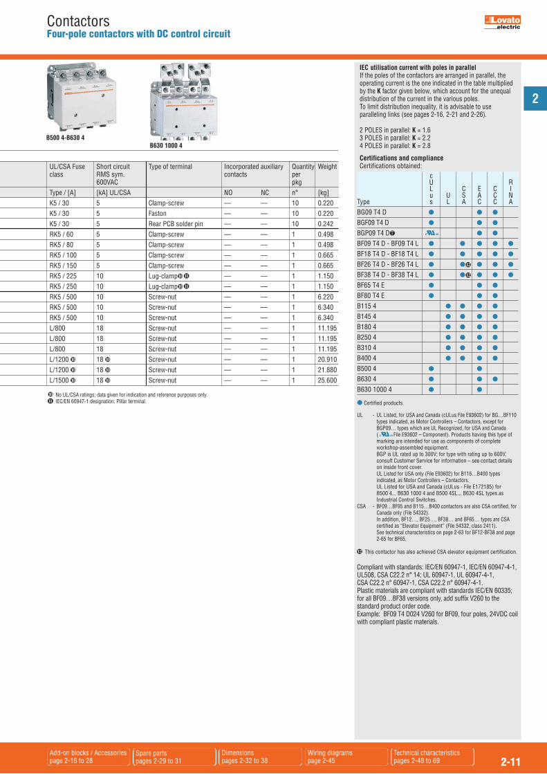
Certifications and complianceCertifications obtained:
B630 1000 4 B500 4-B630 4
IEC utilisation current with poles in parallelIf the poles of the contactors are arranged in parallel, theoperating current is the one indicated in the table multipliedby the K factor given below, which account for the unequaldistribution of the current in the various poles.To limit distribution inequality, it is advisable to useparalleling links (see pages 2-16, 2-21 and 2-26).
2 POLES in parallel: K = 1.63 POLES in parallel: K = 2.24 POLES in parallel: K = 2.8
c U R L C E C I u U S A C NType s L A C C ABG09 T4 D � � �
BGF09 T4 D � � �
BGP09 T4 D � �
BF09 T4 D - BF09 T4 L � � � � �
BF18 T4 D - BF18 T4 L � � � � �
BF26 T4 D - BF26 T4 L � � � � �
BF38 T4 D - BF38 T4 L � � � � �
BF65 T4 E � � �
BF80 T4 E � � �
B115 4 � � � �
B145 4 � � � �
B180 4 � � � �
B250 4 � � � �
B310 4 � � � �
B400 4 � � � �
B500 4 � �B630 4 � � �
B630 1000 4 � �
12
12
12
UL/CSA Fuse Short circuit Type of terminal Incorporated auxiliary Quantity Weight class RMS sym. contacts per 600VAC pkg Type / [A] [kA] UL/CSA NO NC n° [kg] K5 / 30 5 Clamp-screw –– –– 10 0.220 K5 / 30 5 Faston –– –– 10 0.220 K5 / 30 5 Rear PCB solder pin –– –– 10 0.242 RK5 / 60 5 Clamp-screw –– –– 1 0.498 RK5 / 80 5 Clamp-screw –– –– 1 0.498 RK5 / 100 5 Clamp-screw –– –– 1 0.665 RK5 / 150 5 Clamp-screw –– –– 1 0.665 RK5 / 225 10 Lug-clamp� –– –– 1 1.150 RK5 / 250 10 Lug-clamp� –– –– 1 1.150 RK5 / 500 10 Screw-nut –– –– 1 6.220 RK5 / 500 10 Screw-nut –– –– 1 6.340 RK5 / 500 10 Screw-nut –– –– 1 6.340 L/800 18 Screw-nut –– –– 1 11.195 L/800 18 Screw-nut –– –– 1 11.195 L/800 18 Screw-nut –– –– 1 11.195 L/1200 � 18 � Screw-nut –– –– 1 20.910 L/1200 � 18 � Screw-nut –– –– 1 21.880 L/1500 � 18 � Screw-nut –– –– 1 25.600
11
11
� No UL/CSA ratings; data given for indication and reference purposes only.� IEC/EN 60947-1 designation: Pillar terminal.11
2
2-12Add-on blocks / Accessoriespage 2-16 to 25
Spare partspages 2-29 to 31
Dimensionspages 2-32 to 33
Wiring diagrams page 2-45
Technical characteristics pages 2-48 to 63 and 69
ContactorsFour-pole contactors with control circuit: AC and DC
Order code IEC rated conventional Qty Wt free air thermal current Ith per �40°C �55°C �60°C pkg [A] [A] [A] n° [kg] AC COIL. Terminals: clamp screw. BF09 T2 A� 25 20 18 1 0.340 BF18 T2 A� 32 26 23 1 0.340 BF26 T2 A� 45 36 32 1 0.420 BF38 T2 A� 56 (60�) 45 (48�) 40 (42�) 1 0.420 BF80 T2 A� 115 95 75 1 1.075 DC COIL. Terminals: clamp screw. BF18 T2 D�� 32 26 23 1 0.470 BF26 T2 D�� 45 36 32 1 0.540 BF38 T2 D�� 56 (60�) 45 (48�) 40 (42�) 1 0.540 BF80 T2 E� 115 95 75 1 1.125 DC COIL. Low consumption (2.4W). Terminals: clamp screw. BF18 T2 L�� 32 26 23 1 0.470 BF26 T2 L�� 45 36 32 1 0.540 BF38 T2 L�� 56 (60�) 45 (48�) 40 (42�) 1 0.540
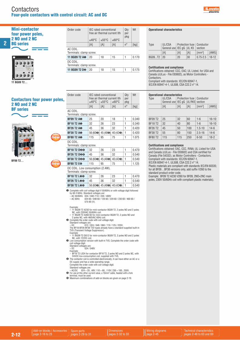
Contactors four power poles,2 NO and 2 NC BF series
BF09 T2...
Mini-contactor four power poles,2 NO and 2 NC BG series
Order code IEC rated conventional Qty Wt free air thermal current Ith per pkg �40°C �55°C �60°C [A] [A] [A] n° [kg] AC COIL. Terminals: clamp screw. 11 BG09 T2 A� 20 18 15 1 0.170 DC COIL. Terminals: clamp screw. 11 BG09 T2 D� 20 18 15 1 0.175
11 BG09 T2...
� Complete with coil voltage digit if 50/60Hz or with voltage digit followedby 60 if 60Hz. Standard voltages are:
– AC 50/60Hz 024 / 048 /110 / 230 / 400V – AC 60Hz 024 60 / 048 60 / 120 60 / 220 60 / 230 60 / 460 60 /
575 60 (V).
Example: – 11 BG09 T2 A230 for mini-contactor BG09 T2, 2 poles NO and 2 poles
NC, with 230VAC 50/60Hz coil. – 11 BG09 T2 A460 60 for mini-contactor BG09 T2, 2 poles NO and
2 poles NC, with 460VAC 60Hz coil.� Complete the order code with coil voltage digit.
Standard voltages are: -- DC 012 / 024 / 048 / 060 / 110 / 125 / 220V.
The BF18-BF26-BF38 T2D types already have a standard supplied built-inTVS (Transient Voltage Suppressor).
Example: – 11 BG09 T2 D012 for mini-contactor BG09 T2, 2 poles NO and 2 poles
NC, with 12VDC coil.� Low consumption version with built-in TVS. Complete the order code with
coil voltage digit.Standard voltages are:
-- DC 024 / 048V. Example: – BF18 T2 L024 for contactor BF18 T2, 2 poles NO and 2 poles NC, with
24VDC low-consumption coil, supplied with TVS.� The contactor coil is controlled electronically; it can have either an AC or a
DC supply and has a wide operating range. Complete the order code with coil voltage digit. Standard voltages are: – AC/DC 024 = 20...48V; 110 = 60...110V; 230 = 100...250V.� For use at this other current value, a 16mm2 cable, headed with a fork
terminal, must be used.� Maximum combinations of add-on blocks are given on page 2-19.
Operational characteristics
Type UL/CSA Protection fuse Conductor General use IEC gG UL K5 section [A] [A] [A] [mm2] [AWG]BG09...T2 20 20 30 0.75-2.5 18-12
Certifications and complianceCertifications obtained: CCC, EAC; UL Listed, for USA andCanada (cULus - File E93602), as Motor Controllers -Contactors.Compliant with standards: IEC/EN 60947-1, IEC/EN 60947-4-1, UL508, CSA C22.2 n° 14.
Operational characteristicsType UL/CSA Protection fuse Conductor General use IEC gG ULRK5 section [A] [A] [A] [mm2] [AWG]
BF09 T2 25 32 60 1-6 16-10BF18 T2 32 40 80 1-6 16-10BF26 T2 45 50 100 1.5-10 14-6BF38 T2 55 80 150 2.5-16 14-6BF80 T2 115 115 250 6-50 18-2
Certifications and complianceCertifications obtained: EAC, CCC, RINA; UL Listed for USAand Canada (cULus - File E93602) and CSA certified forCanada (File 54332), as Motor Controllers - Contactors.Compliant with standards: IEC/EN 60947-1,IEC/EN 60947-4-1, UL508, CSA C22.2 n° 14.Plastic materials are compliant with standards IEC/EN 60335;for all BF09…BF38 versions only, add suffix V260 to thestandard product order code.Example: BF09 T2 A230 V260 for BF09, 2NO+2NC mainpoles, 230V 50/60Hz coil with compliant plastic materials).
2
2-13Add-on blocks / Accessoriespage 2-16 to 25
Spare partspages 2-29 and 31
Dimensionspages 2-32 and 33
Wiring diagrams page 2-45
Technical characteristics pages 2-48 to 63 and 69
ContactorsFour-pole contactors with control circuit: AC and DC
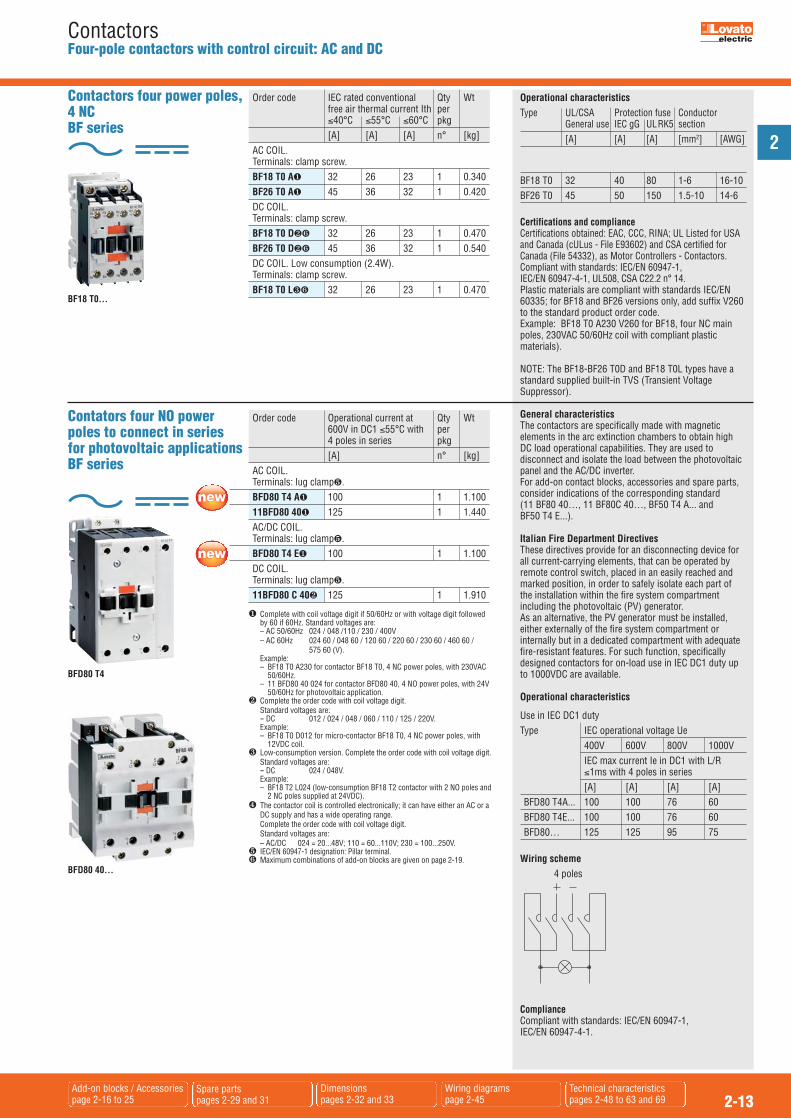
Contactors four power poles, 4 NC BF series
Order code IEC rated conventional Qty Wt free air thermal current Ith per �40°C �55°C �60°C pkg [A] [A] [A] n° [kg] AC COIL. Terminals: clamp screw. BF18 T0 A� 32 26 23 1 0.340 BF26 T0 A� 45 36 32 1 0.420 DC COIL. Terminals: clamp screw. BF18 T0 D�� 32 26 23 1 0.470 BF26 T0 D�� 45 36 32 1 0.540 DC COIL. Low consumption (2.4W). Terminals: clamp screw. BF18 T0 L�� 32 26 23 1 0.470
Contators four NO powerpoles to connect in seriesfor photovoltaic applicationsBF series
Order code Operational current at Qty Wt 600V in DC1 �55°C with per 4 poles in series pkg [A] n° [kg] AC COIL. Terminals: lug clamp�. BFD80 T4 A� 100 1 1.100 11BFD80 40� 125 1 1.440 AC/DC COIL. Terminals: lug clamp�. BFD80 T4 E� 100 1 1.100 DC COIL. Terminals: lug clamp�. 11BFD80 C 40� 125 1 1.910
BF18 T0...
� Complete with coil voltage digit if 50/60Hz or with voltage digit followedby 60 if 60Hz. Standard voltages are:
– AC 50/60Hz 024 / 048 /110 / 230 / 400V – AC 60Hz 024 60 / 048 60 / 120 60 / 220 60 / 230 60 / 460 60 / 575 60 (V). Example: – BF18 T0 A230 for contactor BF18 T0, 4 NC power poles, with 230VAC
50/60Hz. – 11 BFD80 40 024 for contactor BFD80 40, 4 NO power poles, with 24V
50/60Hz for photovoltaic application.� Complete the order code with coil voltage digit. Standard voltages are: -- DC 012 / 024 / 048 / 060 / 110 / 125 / 220V. Example: – BF18 T0 D012 for micro-contactor BF18 T0, 4 NC power poles, with
12VDC coil.� Low-consumption version. Complete the order code with coil voltage digit.
Standard voltages are: -- DC 024 / 048V. Example: – BF18 T2 L024 (low-consumption BF18 T2 contactor with 2 NO poles and
2 NC poles supplied at 24VDC).� The contactor coil is controlled electronically; it can have either an AC or a
DC supply and has a wide operating range. Complete the order code with coil voltage digit. Standard voltages are: – AC/DC 024 = 20...48V; 110 = 60...110V; 230 = 100...250V.� IEC/EN 60947-1 designation: Pillar terminal.� Maximum combinations of add-on blocks are given on page 2-19.
BFD80 T4
BFD80 40...
General characteristicsThe contactors are specifically made with magneticelements in the arc extinction chambers to obtain highDC load operational capabilities. They are used todisconnect and isolate the load between the photovoltaicpanel and the AC/DC inverter.For add-on contact blocks, accessories and spare parts,consider indications of the corresponding standard (11 BF80 40…, 11 BF80C 40…, BF50 T4 A... andBF50 T4 E...).
Italian Fire Department DirectivesThese directives provide for an disconnecting device forall current-carrying elements, that can be operated byremote control switch, placed in an easily reached andmarked position, in order to safely isolate each part ofthe installation within the fire system compartmentincluding the photovoltaic (PV) generator.As an alternative, the PV generator must be installed,either externally of the fire system compartment orinternally but in a dedicated compartment with adequatefire-resistant features. For such function, specificallydesigned contactors for on-load use in IEC DC1 duty upto 1000VDC are available.
Operational characteristics
Use in IEC DC1 dutyType IEC operational voltage Ue
400V 600V 800V 1000VIEC max current Ie in DC1 with L/R �1ms with 4 poles in series[A] [A] [A] [A]
BFD80 T4A... 100 100 76 60BFD80 T4E... 100 100 76 60BFD80… 125 125 95 75
Wiring scheme 4 poles
ComplianceCompliant with standards: IEC/EN 60947-1, IEC/EN 60947-4-1.
Operational characteristicsType UL/CSA Protection fuse Conductor General use IEC gG ULRK5 section [A] [A] [A] [mm2] [AWG]
BF18 T0 32 40 80 1-6 16-10BF26 T0 45 50 150 1.5-10 14-6
Certifications and complianceCertifications obtained: EAC, CCC, RINA; UL Listed for USAand Canada (cULus - File E93602) and CSA certified forCanada (File 54332), as Motor Controllers - Contactors.Compliant with standards: IEC/EN 60947-1,IEC/EN 60947-4-1, UL508, CSA C22.2 n° 14.Plastic materials are compliant with standards IEC/EN60335; for BF18 and BF26 versions only, add suffix V260to the standard product order code.Example: BF18 T0 A230 V260 for BF18, four NC mainpoles, 230VAC 50/60Hz coil with compliant plasticmaterials).
NOTE: The BF18-BF26 T0D and BF18 T0L types have astandard supplied built-in TVS (Transient VoltageSuppressor).

2
2-14Add-on blocks / Accessoriespage 2-16 to 25
Spare partspages 2-28 to 31
Dimensionspages 2-39
Wiring diagrams page 2-44
Technical characteristics page 2-56 and 57
ContactorsContactors for power factor correction with AC control circuit
Operational characteristics IEC rated IEC - UL/CSA Type operational protection fuse current �440V gG-SC [A] [A]
BFK09 12 16BFK12 18 25BFK18 23 40BFK26 30 40BFK32 36 63BFK38 43 63BFK50 58 80BFK65 65 100BFK80 75 125BF80K 90 125BF110K 110 160Ambient operating temperature: �50°C. For ambienttemperatures higher than 50°C and up to 70°C, themaximum operating power values indicated in the tablemust be reduced by a percentage equal to the differencebetween the operating ambient temperature and 50°C.E.g.: Using a BFK26 00 contactor at the ambienttemperature of 60°C, the maximum operating power (at 400V) of the contactor will be equal to 20kvar – 10% =18kvar.Operating cycle: �120 cycles/hElectrical life: �400,000 cycles.
Add-on auxiliary contacts The following contact blocks, can be fitted on the BFKcontactors: BFX12..., G418..., G481..., G482... and G218.
Certifications and complianceCertification obtained: CCC, EAC; UL Listed for USA andCanada (cULus - File E93602), as Motor Controllers -Magnetic Capacitive Switches.Compliant with standards: IEC/EN 60947-1, IEC/EN 60947-4-1, UL508, CSA C22.2 n° 14.Plastic materials are compliant with standards IEC/EN 60335;for BFK versions only, add suffix V260 to the standardproduct order code.
General characteristicsTo optimise contactor stock management, a kit is availableto transform normal three-pole contactors into BFK types for power factor correction. The table to the leftindicates which kits to purchase depending on the standardcontactor in stock.
Order code Maximum IEC operational Qty Wt power at �50°C (AC-6b)� per 240V 400V 440V 690V � pkg 480V [kvar] [kvar] [kvar] [kvar] NO n° [kg] AC COIL. BFK09 10A� 4,5 7,5 9 10 1 10 0.413 BFK12 10A� 7 12,5 14 16 1 10 0.413 BFK18 10A� 9 15 17 20 1 10 0.413 BFK26 00A� 11 20 22 25 – 10 0.472 BFK32 00A� 14 25 27,5 30 – 10 0.472 BFK38 00A� 17 30 33 36 – 10 0.472 BFK50 00A� 22 40 41 46 – 5 1.080 BFK65 00A� 26 45 50 56 – 5 1.080 BFK80 00A� 30 50 56 65 – 5 1.080 11 BF80K 00� 34 60 65 70 – 5 1.470 11 BF110K 00�� 45 75 80 100 – 5 1.470
� To use the contactor in the delta, consult our Customer Service office,see contact details on front cover.
� NO auxiliary contacts available.� The order code must be completed either with the coil voltage digit if
50/60Hz or with the coil voltage digit followed by the number 60 if 60Hz. Standard voltages are: -- AC 50-60Hz 024 / 048 / 110 / 230 / 400VAC -- AC 60Hz 024 60 / 048 60 / 120 60 / 220 60 / 230 60 / 460 60 / 575 60 (V). Example: BFK09 10 A230 for contactor BFK09 with one NO contact
and 230VAC 50/60Hz coil. BFK09 10 A460 60 for contactor BFK09 with one NO
contact and 460VAC 60Hz coil.� Note: the maximum thermal current Ith of the BF110K contactor is 125A.
BFK contactors (includinglimiting resistors)
Order code For contactor Qty Wt per pkg n° [kg] 11 G460 BF09 10A - BF12 10A - 10 0.072 BF18 10A - BF26 00A - BF32 00A - BF38 00A BFX10K3 BF50 00A - BF65 00A - 10 0.078 BF80 00A 11 G464 BF80 00 - BF110 00 10 0.080
Kit to assemble BFKcontactors
BFK...
11 G46...
2
2-15Add-on blocks / Accessoriespage 2-16 to 25
Spare partspages 2-28 and 29
Dimensionspages 2-32 and 33
Wiring diagrams page 2-45
Technical characteristics pages 2-58 and 69
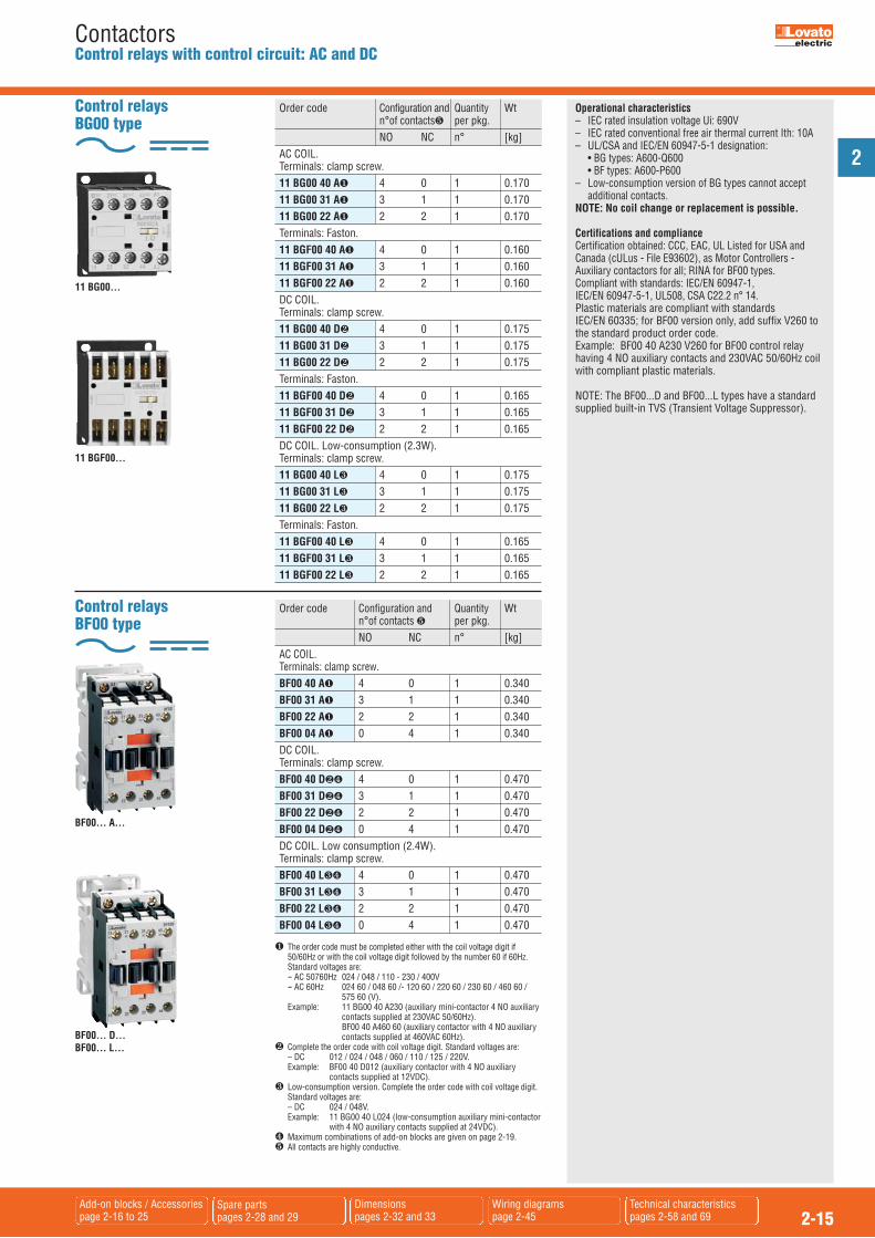
ContactorsControl relays with control circuit: AC and DC
BF00... A...
� The order code must be completed either with the coil voltage digit if50/60Hz or with the coil voltage digit followed by the number 60 if 60Hz.
Standard voltages are: -- AC 50760Hz 024 / 048 / 110 - 230 / 400V -- AC 60Hz 024 60 / 048 60 /- 120 60 / 220 60 / 230 60 / 460 60 / 575 60 (V). Example: 11 BG00 40 A230 (auxiliary mini-contactor 4 NO auxiliary
contacts supplied at 230VAC 50/60Hz). BF00 40 A460 60 (auxiliary contactor with 4 NO auxiliary
contacts supplied at 460VAC 60Hz).� Complete the order code with coil voltage digit. Standard voltages are: – DC 012 / 024 / 048 / 060 / 110 / 125 / 220V. Example: BF00 40 D012 (auxiliary contactor with 4 NO auxiliary
contacts supplied at 12VDC).� Low-consumption version. Complete the order code with coil voltage digit.
Standard voltages are: – DC 024 / 048V. Example: 11 BG00 40 L024 (low-consumption auxiliary mini-contactor
with 4 NO auxiliary contacts supplied at 24VDC).� Maximum combinations of add-on blocks are given on page 2-19.� All contacts are highly conductive.
Order code Configuration and Quantity Wt n°of contacts � per pkg. NO NC n° [kg] AC COIL. Terminals: clamp screw. BF00 40 A� 4 0 1 0.340 BF00 31 A� 3 1 1 0.340 BF00 22 A� 2 2 1 0.340 BF00 04 A� 0 4 1 0.340 DC COIL. Terminals: clamp screw. BF00 40 D�� 4 0 1 0.470 BF00 31 D�� 3 1 1 0.470 BF00 22 D�� 2 2 1 0.470 BF00 04 D�� 0 4 1 0.470 DC COIL. Low consumption (2.4W). Terminals: clamp screw. BF00 40 L�� 4 0 1 0.470 BF00 31 L�� 3 1 1 0.470 BF00 22 L�� 2 2 1 0.470 BF00 04 L�� 0 4 1 0.470
Control relays BF00 type
Operational characteristics– IEC rated insulation voltage Ui: 690V– IEC rated conventional free air thermal current Ith: 10A– UL/CSA and IEC/EN 60947-5-1 designation: • BG types: A600-Q600 • BF types: A600-P600– Low-consumption version of BG types cannot accept
additional contacts.NOTE: No coil change or replacement is possible.
Certifications and complianceCertification obtained: CCC, EAC, UL Listed for USA andCanada (cULus - File E93602), as Motor Controllers -Auxiliary contactors for all; RINA for BF00 types.Compliant with standards: IEC/EN 60947-1,IEC/EN 60947-5-1, UL508, CSA C22.2 n° 14.Plastic materials are compliant with standards IEC/EN 60335; for BF00 version only, add suffix V260 tothe standard product order code.Example: BF00 40 A230 V260 for BF00 control relayhaving 4 NO auxiliary contacts and 230VAC 50/60Hz coilwith compliant plastic materials.
NOTE: The BF00...D and BF00...L types have a standardsupplied built-in TVS (Transient Voltage Suppressor).
Control relaysBG00 type
Order code Configuration and Quantity Wt n°of contacts� per pkg. NO NC n° [kg] AC COIL. Terminals: clamp screw. 11 BG00 40 A� 4 0 1 0.170 11 BG00 31 A� 3 1 1 0.170 11 BG00 22 A� 2 2 1 0.170 Terminals: Faston. 11 BGF00 40 A� 4 0 1 0.160 11 BGF00 31 A� 3 1 1 0.160 11 BGF00 22 A� 2 2 1 0.160 DC COIL. Terminals: clamp screw. 11 BG00 40 D� 4 0 1 0.175 11 BG00 31 D� 3 1 1 0.175 11 BG00 22 D� 2 2 1 0.175 Terminals: Faston. 11 BGF00 40 D� 4 0 1 0.165 11 BGF00 31 D� 3 1 1 0.165 11 BGF00 22 D� 2 2 1 0.165 DC COIL. Low-consumption (2.3W). Terminals: clamp screw. 11 BG00 40 L� 4 0 1 0.175 11 BG00 31 L� 3 1 1 0.175 11 BG00 22 L� 2 2 1 0.175 Terminals: Faston. 11 BGF00 40 L� 4 0 1 0.165 11 BGF00 31 L� 3 1 1 0.165 11 BGF00 22 L� 2 2 1 0.165
11 BG00...
11 BGF00...
BF00... D...BF00... L...

2
2-16Dimensionspage 2-39
Wiring diagrams page 2-46
Technical characteristics pages 2-48 to 61 and 69
ContactorsAdd-on blocks and accessories for BG series mini-contactors
Order code Characteristics Max Qty Wt qty per per pkg contactor. n° n ° [kg] Auxiliary contacts. Screw terminals. 11 BGX10 02� 2NC 1 10 0.021 11 BGX10 11� 1NO + 1NC 1 10 0.021 11 BGX10 20� 2NO 1 10 0.021 11 BGX10 04� 4NC 1 10 0.028 11 BGX10 13� 1NO + 3NC 1 10 0.028 11 BGX10 22� 2NO + 2NC 1 10 0.028 11 BGX10 31� 3NO + 1NC 1 10 0.028 11 BGX10 40� 4NO 1 10 0.028 Auxiliary contacts for reversing and changeover assemblies. Screw terminals. 11 BGX11 11� 1NO + 1NC 1 10 0.021 11 BGX11 22� 2NO + 2NC 1 10 0.028 Auxiliary contacts. Faston terminals. 11 BGXF10 02� 2NC 1 10 0.021 11 BGXF10 11� 1NO + 1NC 1 10 0.021 11 BGXF10 20� 2NO 1 10 0.021 11 BGXF10 04� 4NC 1 10 0.028 11 BGXF10 13� 1NO + 3NC 1 10 0.028 11 BGXF10 22� 2NO + 2NC 1 10 0.028 11 BGXF10 31� 3NO + 1NC 1 10 0.028 11 BGXF10 40� 4NO 1 10 0.028 Mechanical interlock. 11 BGX50 00� For BG...A and BG...D 1 10 0.008 Quick connect surge suppressors. 11 BGX77 048 �48VAC/DC (Varistor) 10 0.007 11 BGX77 125 48...125VAC/DC (Varistor) 10 0.007 11 BGX77 240 125...240VAC/DC (Varistor) 10 0.007 11 BGX78 225 �225VDC (Diode) 10 0.007 11 BGX79 048 �48VAC (Resistor-Capacitor) 10 0.007 11 BGX79 125 48...125VAC 10 0.007 (Resistor-Capacitor) 11 BGX79 240 125...240VAC 10 0.007 (Resistor-Capacitor) 11 BGX79 415 240...415VAC 10 0.007 (Resistor-Capacitor) Modular shroud. 11 BGX80 00� IP40 front protection 20 0.006 Paralleling links. 11 G323� For 2 poles 10 0.009 11 G324 10 0.009 11 G325� For 4 poles 10 0.014 11 G326 10 0.014 Rigid connecting kits. 11 SMX90 21� Rigid connections for 10 0.040 star-delta starter with BG... mini-contactors 11 SMX90 22� Rigid connections for 1 0.026 reversing switches with BG... mini-contactors
11 BGX10... (20-11-02)11 BGX11 11
11 BGX10... (40-31-22-13-04)11 BGX11 22
11 BGX50 00
11 BGX77... - 11 BGX78 225 -11 BGX79...
11 BGXF...
Operational characteristicsType BGX10... BGXF10... BGX11...IEC rated conventional free A 10 10air thermal current IthIEC rated insulation V 690 690voltage Ui Terminals Screw M3 Faston 1x6.3mm 2x2.8mm Width mm 6.9 6.9Tightening torque Nm 0.8...1 –– lbin 7...9 ––Conductor section maximum(with 1 or 2 cables) flexible without lug mm2 2.5 2.5 flexible with lug mm2 2.5 2.5 AWG n° 14 14UL/CSA and AC A600 A600IEC/EN 60947-5-1 DC Q600 Q600designationMechanical life cycles 20 20(million)
SM1 breaker - mini-contactor connecting kitSee page 1-7.
Certifications and complianceCertifications obtained: Type UL cULus EAC CCC BGX10... –– � � �
BGX11... –– � � �
BGXF10... –– � � ––BGX50 00 –– � � ––BGX7... –– � � ––BGX80 00 –– –– � ––G32... –– –– � ––SMX90... –– –– ––
� Certified products;
- UL Recognized for USA only (File E197069) as Panel andSwitchboard Accessories - Component.
Products having this type of marking are intended for use as components of complete workshop-assembled
equipment.cULus - UL Listed for USA and Canada (cULus - File E93601) as
Auxiliary Devices - Component.
Compliant with standards: UL508, CSA C22.2 n° 14,IEC/EN 60947-1; IEC/EN 60947-5-1 for auxiliarycontacts.
� Cannot be used with BG...L types.� Cannot be used with BG...D and BG...L types.� Suitable for left-hand mini-contactor only of BGT and BGTP reversing and
BGC changeover assemblies.� The shroud can be used with BG... types with screw termination only and
with no auxiliary contacts, surge suppressor or mechanical interlockmounted. It raises the front degree of protection of the mini-contactorwhen these are used in consumer switchboards.
� Cannot be used with BGX80 00 shroud.� Contactors with one NC auxiliary contact, 01 type, are usually used. The SM1 breaker can be directly fitted with rigid connector; type connection
SM1X30 40P for SM1P... breaker and connection SM1X30 40R forSM1R... breaker.
The relay cannot be directly mounted on the contator. Use the RF38 type andthe RFX38 04 independent mounting base.
11 SMX90 2111 SMX90 22
2
2-17Dimensionspage 2-39
Wiring diagrams page 2-46
Technical characteristics pages 2-48 to 61 and 69
ContactorsAdd-on blocks and accessories for BG series mini-contactors
BGX80 00
BG...ABG...D
G323
G324
G325
G326
BGX77...BGX78 225BGX79...
BGX10 40 - BGXF10 40BGX10 31 - BGXF10 31BGX10 22 - BGXF10 22BGX10 13 - BGXF10 13BGX10 04 - BGXF10 04
BGX10 20 - BGXF10 20BGX10 11 - BGXF10 11BGX10 02 - BGXF10 02
BGX80 00
BG...L
G323
G324
G325
G326
BGX77...BGX78 225BGX79...
BG...ABG...D
BGX77...BGX78 225BGX79...
BGX10 40 - BGXF10 40BGX10 31 - BGXF10 31BGX10 22 - BGXF10 22BGX10 13 - BGXF10 13BGX10 04 - BGXF10 04
BGX10 20 - BGXF10 20BGX10 11 - BGXF10 11BGX10 02 - BGXF10 02
BGX77...BGX78 225BGX79...
BGX10 10 - BGXF10 20BGX10 11 - BGXF10 11BGX10 02 - BGXF10 02BGX11 11
BGX10 40 - BGXF10 40BGX10 31 - BGXF10 31BGX10 22 - BGXF10 22BGX10 13 - BGXF10 13BGX10 04 - BGXF10 04BGX11 22
BGX50 00
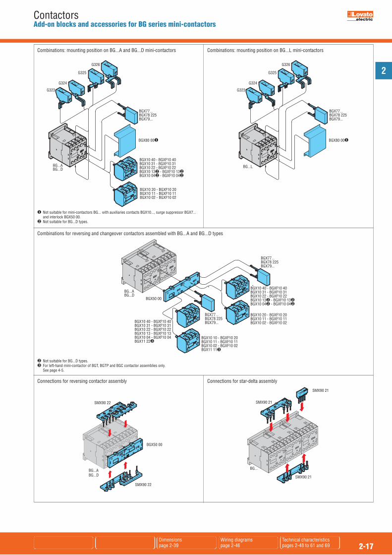
Combinations: mounting position on BG...A and BG...D mini-contactors
Combinations for reversing and changeover contactors assembled with BG...A and BG...D types
Combinations: mounting position on BG...L mini-contactors
� Not suitable for BG...D types.� For left-hand mini-contactor of BGT, BGTP and BGC contactor assemblies only. See page 4-5.
� Not suitable for mini-contactors BG... with auxiliaries contacts BGX10..., surge suppressor BGX7... and interlock BGX50 00.� Not suitable for BG...D types.
Connections for reversing contactor assembly Connections for star-delta assembly
SMX90 21
SMX90 21
SMX90 21
BGX50 00
SMX90 22
BG...ABG...D
SMX90 22
BG...
2
2-18Dimensionspage 2-40
Wiring diagrams pagee 2-46 and 47
Technical characteristics pages 2-48 to 65 and 69
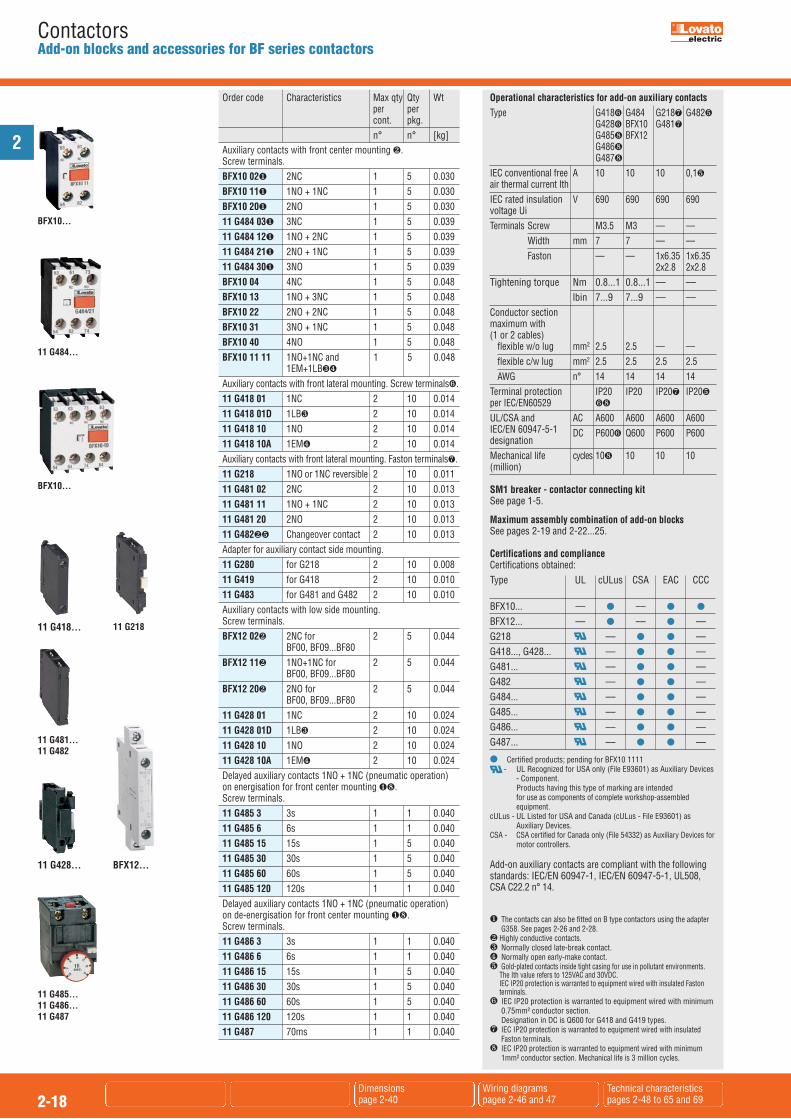
ContactorsAdd-on blocks and accessories for BF series contactors
Order code Characteristics Max qty Qty Wt per per cont. pkg. n° n° [kg] Auxiliary contacts with front center mounting �. Screw terminals. BFX10 02� 2NC 1 5 0.030 BFX10 11� 1NO + 1NC 1 5 0.030 BFX10 20� 2NO 1 5 0.030 11 G484 03� 3NC 1 5 0.039 11 G484 12� 1NO + 2NC 1 5 0.039 11 G484 21� 2NO + 1NC 1 5 0.039 11 G484 30� 3NO 1 5 0.039 BFX10 04 4NC 1 5 0.048 BFX10 13 1NO + 3NC 1 5 0.048 BFX10 22 2NO + 2NC 1 5 0.048 BFX10 31 3NO + 1NC 1 5 0.048 BFX10 40 4NO 1 5 0.048 BFX10 11 11 1NO+1NC and 1 5 0.048 1EM+1LB��
Auxiliary contacts with front lateral mounting. Screw terminals�. 11 G418 01 1NC 2 10 0.014 11 G418 01D 1LB� 2 10 0.014 11 G418 10 1NO 2 10 0.014 11 G418 10A 1EM� 2 10 0.014 Auxiliary contacts with front lateral mounting. Faston terminals. 11 G218 1NO or 1NC reversible 2 10 0.011 11 G481 02 2NC 2 10 0.013 11 G481 11 1NO + 1NC 2 10 0.013 11 G481 20 2NO 2 10 0.013 11 G482�� Changeover contact 2 10 0.013 Adapter for auxiliary contact side mounting. 11 G280 for G218 2 10 0.008 11 G419 for G418 2 10 0.010 11 G483 for G481 and G482 2 10 0.010 Auxiliary contacts with low side mounting. Screw terminals. BFX12 02� 2NC for 2 5 0.044 BF00, BF09...BF80 BFX12 11� 1NO+1NC for 2 5 0.044 BF00, BF09...BF80 BFX12 20� 2NO for 2 5 0.044 BF00, BF09...BF80 11 G428 01 1NC 2 10 0.024 11 G428 01D 1LB� 2 10 0.024 11 G428 10 1NO 2 10 0.024 11 G428 10A 1EM� 2 10 0.024 Delayed auxiliary contacts 1NO + 1NC (pneumatic operation) on energisation for front center mounting �. Screw terminals. 11 G485 3 3s 1 1 0.040 11 G485 6 6s 1 1 0.040 11 G485 15 15s 1 5 0.040 11 G485 30 30s 1 5 0.040 11 G485 60 60s 1 5 0.040 11 G485 120 120s 1 1 0.040 Delayed auxiliary contacts 1NO + 1NC (pneumatic operation) on de-energisation for front center mounting �. Screw terminals. 11 G486 3 3s 1 1 0.040 11 G486 6 6s 1 1 0.040 11 G486 15 15s 1 5 0.040 11 G486 30 30s 1 5 0.040 11 G486 60 60s 1 5 0.040 11 G486 120 120s 1 1 0.040 11 G487 70ms 1 1 0.040
Operational characteristics for add-on auxiliary contactsType G418� G484 G218 G482� G428� BFX10 G481 G485 BFX12 G486 G487
IEC conventional free A 10 10 10 0,1�air thermal current IthIEC rated insulation V 690 690 690 690voltage Ui Terminals Screw M3.5 M3 –– –– Width mm 7 7 –– –– Faston –– –– 1x6.35 1x6.35 2x2.8 2x2.8Tightening torque Nm 0.8...1 0.8...1 –– –– lbin 7...9 7...9 –– ––Conductor sectionmaximum with (1 or 2 cables) flexible w/o lug mm2 2.5 2.5 –– –– flexible c/w lug mm2 2.5 2.5 2.5 2.5 AWG n° 14 14 14 14Terminal protection IP20 IP20 IP20 IP20�per IEC/EN60529 �
UL/CSA and AC A600 A600 A600 A600IEC/EN 60947-5-1 DC P600� Q600 P600 P600designationMechanical life cycles 10 10 10 10(million)
SM1 breaker - contactor connecting kitSee page 1-5.
Maximum assembly combination of add-on blocksSee pages 2-19 and 2-22...25.
Certifications and complianceCertifications obtained:Type UL cULus CSA EAC CCC BFX10... –– � –– � �
BFX12... –– � –– � ––G218 –– � � ––G418..., G428... –– � � ––G481... –– � � ––G482 –– � � ––G484... –– � � ––G485... –– � � ––G486... –– � � ––G487... –– � � ––
� Certified products; pending for BFX10 1111- UL Recognized for USA only (File E93601) as Auxiliary Devices
- Component. Products having this type of marking are intended for use as components of complete workshop-assembled
equipment.cULus - UL Listed for USA and Canada (cULus - File E93601) as
Auxiliary Devices.CSA - CSA certified for Canada only (File 54332) as Auxiliary Devices for
motor controllers.
Add-on auxiliary contacts are compliant with the followingstandards: IEC/EN 60947-1, IEC/EN 60947-5-1, UL508, CSA C22.2 n° 14.
11 G485... 11 G486... 11 G487
11 G218
11 G481...11 G482
BFX10...
11 G484...
11 G418...
11 G428... BFX12...
BFX10...
� The contacts can also be fitted on B type contactors using the adapterG358. See pages 2-26 and 2-28.
� Highly conductive contacts.� Normally closed late-break contact.� Normally open early-make contact.� Gold-plated contacts inside tight casing for use in pollutant environments.
The Ith value refers to 125VAC and 30VDC. IEC IP20 protection is warranted to equipment wired with insulated Fastonterminals.
� IEC IP20 protection is warranted to equipment wired with minimum0.75mm² conductor section. Designation in DC is Q600 for G418 and G419 types.
IEC IP20 protection is warranted to equipment wired with insulatedFaston terminals.
IEC IP20 protection is warranted to equipment wired with minimum1mm² conductor section. Mechanical life is 3 million cycles.

2
2-19Dimensionspages 2-40 and 41
Wiring diagrams pagee 2-46 and 47
Technical characteristics pages 2-48 to 65
ContactorsAdd-on blocks and accessories for BF series contactors
Front centre mount Front lateral mount Side mount
BFX10 02 BFX10 04 G485... G222...� BFX50 02 G269 2 G418... G428... BFX12 02 BFX10 11 BFX10 13 G486... G272...� BFX50 03 G218 G419+ BFX12 11 � G481... G418... BFX10 20 BFX10 22 G487 G482 G280+ BFX12 20 G218 BFX10 31 G483+ BFX50 00 1 type G481... �
BFX10 40 only G483+ BFX50 01 G318... G482 �
G319 225 G322... n°of blocks n°of blocks n°of blocks n°of blocks n°of blocks n°of blocks 1 type only 1 type only Control relay BF00 A 1 1 1 1 � 1 –– 1 or 2 � 1 or 2 � 1 � Three poles BF09 A...BF25 A 1 1 1 1 � 1 –– 1 or 2 � 1 or 2 � 1 � BF26 A...BF38 A 1 1 1 1 � 1 –– 1 or 2 � 1 or 2 � 1 � BF40 A...BF110 1 1 1 1 � –– 1 1 or 2 � 2 1 � BF40 E...BF80 E 1 1 1 1 � –– 1 1 or 2 � 2 1 � BF95 C...-BF110 C 1 1 1 1 � –– 1 1 or 2 2 –– Four poles BF09 A...BF25 A 1 1 1 1 � 1 –– 1 or 2 1 or 2 � 1 � BF26 A...BF38 A 1 1 1 1 � 1 � –– 1 � 1 or 2 � 1 � BF40 A...BF80 A 1 1 1 1 � –– 1 1 or 2 2 1 � BF40 E...-BF80 E 1 1 1 1 � –– 1 1 or 2 2 2� Cannot be fitted with BFX10… with 4 contacts and G222.� To fit the mechanical interlock, the add-on fourth pole needs to be mounted on the left side of the one of the contactors.� One only side-mount block can be fitted on each contactor whenever the BFX50 0... interlock is mounted.� One BFX10... or delayed G48... contact block can be mounted on the G222 or G272 mechanical latch.� G222 mechanical latch.� G272 mechanical latch. For BF40 80 code BFX53 00 or BFX53 01.
Front centre mount Front lateral Side mount mount
BFX10... BFX10... G485... G222... 1 type only BFX50... BFX12... ...02 ...11 ...20 ...04 ...13 ...22 ...31 ....40 G486... � ...02 ...03 ...00 ...01 �
G487 �
n° of blocks n° of blocks n° of blocks 1 type only 1 type only Control relay BF00 D 1 1 1 1 1 1 1 1 1 BF00 L 1 –– 1 –– 1 1 1 –– –– Three poles BF09 D-BF25 D 1 1 1 1 1 1 1 1 1 BF26 D-BF38 D 1 1 1 1 1 1 1 1 1 BF09 L-BF25 L 1 –– 1 –– 1 1 1 –– –– BF26 L-BF38 L 1 –– 1 –– 1 1 1 –– –– Four poles BF09 D-BF25 D 1 1 1 1 1 1 1 1 1 BF26 D-BF38 D –– 1 –– –– –– 1 1 1 1 1 BF09 L-BF25 L 1 –– 1 –– 1 1 1 –– –– BF26 L-BF38 L –– 1 –– –– –– –– –– 1 1 –– ––� Mounting of BFX50 03 interlock is not possible when BFX10... block with 4 contacts and G222 latch are mounted.� One only side-mount block can be fitted on each contactor whenever the BFX50 0... interlock is mounted.� One BFX10... or delayed G48... contact block can be mounted on the G222 or G272 mechanical latch. To fit the mechanical interlock, the add-on fourth pole needs to be mounted on the left side of the one of the contactors. For other assembly combination, consult Customer Service (Tel. 035 4282422; E-mail: [email protected]).
OR +
+OR OR OR
Maximum assembly combination for alternating-current contactors BF00 A, BF09 A...BF110.Maximum assembly combination for alternating/direct-current contactors BF40 E...BF80 E.Maximum assembly combination for direct-current contactors BF80 C...BF110 C.
Maximum assembly combination for direct-current contactors BF00 D, BF09 D...BF38 DMaximum assembly combination for direct-current contactors BF00 L, BF09 L...BF38 L with low absorption
Cont
acto
rsCo
ntac
tors
BF00 A,BF09 A...BF80 A, BF40 E...BF80 EBF95 C...BF110 C
BF00 D,BF09 D...BF38 D, BF00 L,BF09 L...BF38 L
OR

2
2-20Dimensionspages 2-40 and 41
Wiring diagrams page 2-47
Technical characteristics pages 2-48 to 65 and 69
ContactorsAdd-on blocks and accessories for BF series contactors
Order code Characteristics Max Qty Wt qty per per cont. pkg n° n° [kg] Fourth pole. BFX42 For BF26 A, 1 1 0.100 BF32 A, BF38 A BFXD42 For BF26 D, 1 1 0.108 BF32 D, BF38 D, BF26 L, BF32 L, BF38 L BFX43 For BF40 A... BF80 A 1 1 0.150 and BF40 E...BF80 E Mechanical interlock. BFX50 00� Side mount for 1 5 0.039 BF00, BF09...BF38 BFX50 01� Side mount with 2NC 1 5 0.052 contacts for BF00, BF09...BF38 BFX50 02 Front mount, low 1 5 0.006 profile for BF00, BF09...BF38 BFX50 03 Front mount for 1 5 0.023 BF00, BF09...BF38 BFX89 10 Spacer for interlocking 1 10 0.017 BF09...BF38 AC/DC with types in DC BFX53 00 Side mount for 1 5 0.039 BF40...BF80 A/E BFX53 01 Side mount with 2NC 1 5 0.052 contacts for BF40...BF80 A/E BFX53 03 Front mount for 1 5 0.034 BF40...BF80 A/E 11 G269 2 Front mount for 1 5 0.034 BF95...BF110 Mechanical latch. Screw terminals 11 G222� For BF00, BF09...BF38 1 1 0.070 11 G272� For BF40...BF110 1 1 0.070 Manual closing mechanism. 11 G454 For BF00, BF09...BF38 1 1 0.021 11 G455 For BF40...BF110 1 1 0.021 Quick connect surge suppressors for BF00A, BF09A...BF80A contactors. BFX77 048 �48VAC/DC (Varistor) 5 0.012 BFX77 125 48...125VAC/DC (Varistor) 5 0.012 BFX77 240 125...240VAC/DC (Varistor) 5 0.012 BFX79 048 �48VAC (Resistor-Capacitor) 5 0.012 BFX79 125 48...125VAC (Resistor-Capacitor) 5 0.012 BFX79 240 125...240VAC (Resistor-Capacitor) 5 0.012 BFX79 415 240...415VAC (Resistor-Capacitor) 5 0.012 Surge suppressor for BF95...BF110 contactors, front mount. Faston terminals. 11 G318 48 �48VAC/DC (Varistor) 10 0.010 11 G318 125 48...125VAC/DC (Varistor) 10 0.010 11 G318 240 125...240VAC/DC (Varistor) 10 0.010 11 G318 415 240...415VAC/DC (Varistor) 10 0.010 11 G319 225 �225VDC (Diode) 10 0.010 11 G322 48 �48VAC (Resistor-Capacitor) 10 0.010 11 G322 220 48...240VAC (Resistor-Capacitor) 10 0.010 11 G322 380 240...415VAC (Resistor-Capacitor) 10 0.010 Suppressor mounting adapter for G318-G319-G322. 11 RE244 For 35mm DIN rail 10 0.004
Operational characteristicsType BFX42 BFX43 BFX50 01 BFXD42IEC conventional A 56 115 10free air thermal current IthIEC rated insulation voltage Ui V 690 1000 690Terminals: Screw M4 M6 M3 Width mm 12.5 9.6 7Tightening torque Nm 2.5...3 4...5 0.8...1 lbin 21.6...26.4 35.4...44.2 7...9Conductor sectionmaximum with1 or 2 cables flexible w/o lug mm2 16 35 2.5 flexible c/w lug mm2 16 35 2.5 AWG n° 6 2 14Terminal protection IP20� IP20� IP20per IEC/EN60529UL/CSA and AC –– –– A600IEC/EN 60947-5-1 DC –– –– Q600designationMechanical life cycles 10 15 10(million)
Type G222... G272...Rated control circuitvoltage AC (50/60Hz) V 24...415 24...415 DC V 12...240 12...240Power consumptionwith control: AC VA 40 40 DC W 70 70Minimum energising: drop-out ms 10 10 pick-up ms 100 200Tightening torque Nm 0.8...1 0.8...1 lbin 7...9 7...9Conductor sectionMaximum with1 or 2 cables flexible w/o lug mm2 4 4 flexible c/w lug mm2 2.5 2.5 AWG n° 14...12 14...12
� The condition is front IP20 protection.
Maximum assembly combination of add-on blocksSee pages 2-19, 2-22...25.
Certifications and complianceCertifications obtained:
Type UL cULus CSA EAC BFX42 - BFXD42 - BFXD43 –– � –– �BFX50... –– � –– �BFX77... –– � –– �BFX79... –– � –– �G269 2 –– � �
G222... –– � �
G272... –– � �
� Certified products.- UL Recognized for USA only (File E93601) as Auxiliary Devices
Component. Products having this type of marking are intended for use as components of complete workshop-assembled
equipment.cULus - UL Listed for USA and Canada (cULus - File E93602) as
Magnetic motor controllers.CSA - CSA certified for Canada only (File 54332) as Auxiliary Devices for
motor controllers.
Compliant with standards: IEC/EN 60947-1, IEC/EN 60947-5-1, UL508, CSA C22.2 n° 14.
� Different sized contactors can be interlocked. Example: BF09...BF25 with BF26...BF38.� Replace with the digit of the voltage if 50 or 60Hz and with the letter C
followed by the digit of the voltage if DC.Standard voltages are:
– AC 50/60Hz 24 (indicate 24) - 48 (indicate 48) - 110...125 (indicate 110) 220...240 (indicate 220) - 380...415V (indicate 380). – DC 12 (indicate 12) - 24 (indicate 24) - 48 (indicate 48) 110...125 (indicate 110) - 220...240V (indicate 220).
11 G318... 11 G319 225 11 G322...
11 G45411 G455
11 RE244
BFX77...BFX79...
11 G222...11 G272...
BFX50 00BFX53 00
BFX50 01BFX53 01
BFX50 02 BFX50 03BFX53 0311 G269 2
BFX42BFXD42

2
2-21Dimensionspages 2-40 and 41
Wiring diagrams page 2-47
Technical characteristics pages 2-48 to 65
ContactorsAdd-on blocks and accessories for BF series contactors
Order code Characteristics Qty Wt per pkg n° [kg] Rigid connecting kits for three-pole reversing contactor assembly.
BFX31 01 For contactors 1 0.052 BF09...BF25 side by side with BFX50 02 and BFX50 03 mechanical interlock BFX31 02 For contactors 1 0.054 BF09...BF25side by side with BFX50 00 or BFX50 01 mechanical interlock BFX32 01 For contactors 1 0.060 BF26...BF38 side by side with BFX50... mechanical interlock Rigid connecting kits for star-delta starters. BFX31 31 For contactors BF09...BF25 1 0.058 BFX32 31 For contactors BF26...BF38 1 0.064 BFX32 32 For contactors 1 0.064 BF26...BF38 (L/∆) BF09...BF25 ( ) Sealing cover. BFX80 Sealing cover 10 0.001 for contactors BF00 and BF09 ... BF38 Screw fixing adapters for contactors. BFX89 01 Universal base to screw fix 5 0.016 BF09...BF38 contactors BFX89 02 Screw fixing brackets for 10 0.002 BF09...BF38 contactors Power terminal shroud. 11 G265� IP20 protection for 3-pole 10 0.015 BF95...BF110 types Paralleling links. 11 BA135 2 poles for contactors 10 0.001 BF09...BF25 types 11 BA235 2 poles for contactors 10 0.003 BF26...BF38 types 11 BA435 3 poles for contactors 10 0.030 BF95...BF110 types One-pole enlarged terminals. 11 G231 1x6mm2 for contactors 12 0.009 BF09...BF25 types 11 G232 1x16mm2 for contactors 12 0.014 BF26...BF38 types Three-pole enlarged terminals. 11 G271 1x50mm2 for contactors 10 0.142 BF95...BF110 types � Four-pole enlarged terminals. 11 G288 1x50mm2 for contactors 10 0.194 BF95...BF110 types � Auxiliary terminal. 11 G285 For BF95...BF110 types 8 0.009 Marking element for BF00, BF09...BF110 contactors. BFX30 Blank label for writing 50 0.001� Two pieces are required per contactor.� An additional 1-50mm2 conductor can be fitted in the contactor terminal.
Y
11 BA13511 BA235
11 G265
11 BA435
11 G23111 G232
11 G271
11 G288
11 G285
BFX31...BFX32...
BFX 80
BFX89 01 BFX89 02
Operational characteristics
Type G231 G232 G285 G271 G288Tightening Nm 1.5-1.8 2.5-3 0.8-1 5torque lbin 13.2-18 7-9 7.9 44.3Tool Type PH1 PH2 PH1 Metric Allen 4
Certifications and complianceCertifications obtained: GOST for all; UL Listed, for USAand Canada (cULus - File E93602), under MagneticMotor Controllers for BFX31 01, BFX31 02, BFX32 01, BFX31 31, BFX32 31 and BFX32 32 as rigid kits, G271and G288 as enlarged terminal kits; EAC for all.Compliant with standards: IEC/EN 60947-1, UL508, CSA C22.2 n° 14.
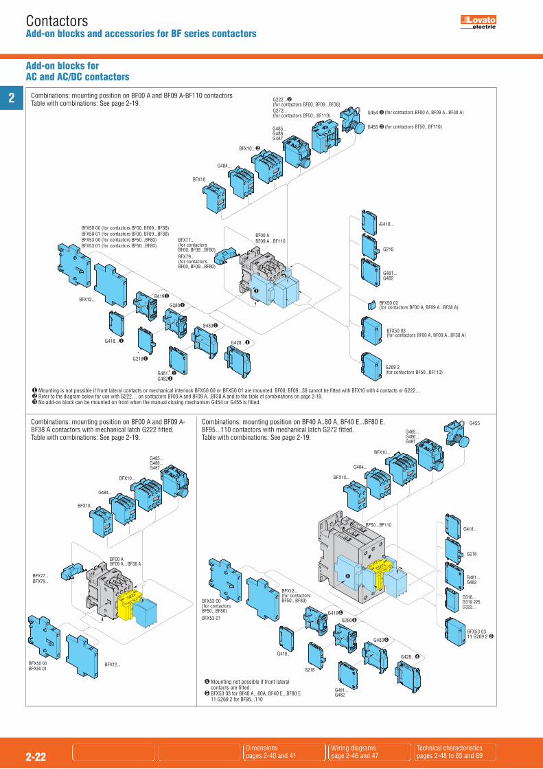
2
2-22Dimensionspages 2-40 and 41
Wiring diagrams page 2-46 and 47
Technical characteristics pages 2-48 to 65 and 69
ContactorsAdd-on blocks and accessories for BF series contactors
Combinations: mounting position on BF00 A and BF09 A-BF110 contactorsTable with combinations: See page 2-19.
BFX10...
G484...
G485...G486...G487
G454 ❸ (for contactors BF00 A, BF09 A...BF38 A)
G455 ❸ (for contactors BF50...BF110)
G418...
G218
G481...G482
G269 2 (for contactors BF50...BF110)
G222...❷(for contactors BF00, BF09...BF38)G272...(for contactors BF50...BF110)
BFX50 02(for contactors BF00 A, BF09 A...BF38 A)
BFX50 03(for contactors BF00 A, BF09 A...BF38 A)
G419❶
G280❶
G483❶
G428...❶G418...❶
G218❶
G481...❶G482❶
BF00 ABF09 A...BF110BFX77...
(for contactorsBF00, BF09...BF80)BFX79...(for contactors BF00, BF09...BF80)
❶
BFX10...❷
BFX12...
BFX50 00 (for contactors BF00, BF09...BF38)BFX50 01 (for contactors BF00, BF09...BF38)BFX53 00 (for contactors BF50...BF80)BFX53 01 (for contactors BF50...BF80)
� Mounting is not possible if front lateral contacts or mechanical interlock BFX50 00 or BFX50 01 are mounted. BF00, BF09...38 cannot be fitted with BFX10 with 4 contacts or G222…� Refer to the diagram below for use with G222… on contactors BF00 A and BF09 A...BF38 A and to the table of combinations on page 2-19.� No add-on block can be mounted on front when the manual closing mechanism G454 or G455 is fitted.
Combinations: mounting position on BF00 A and BF09 A-BF38 A contactors with mechanical latch G222 fitted.Table with combinations: See page 2-19.
BFX53 00(for contactorsBF50...BF80)BFX53 01
BFX53 0311 G269 2 ❺
(for contactorsBF50...BF80)
� Mounting not possible if front lateralcontacts are fitted.
� BFX53 03 for BF40 A...80A, BF40 E...BF80 E11 G269 2 for BF95...110
Add-on blocks forAC and AC/DC contactors
Combinations: mounting position on BF40 A..80 A, BF40 E...BF80 E,BF95...110 contactors with mechanical latch G272 fitted.Table with combinations: See page 2-19.

2
2-23Dimensionspages 2-40 and 41
Wiring diagrams page 2-46 and 47
Technical characteristics pages 2-48 to 65 and 69
ContactorsAdd-on blocks and accessories for BF series contactors
Add-on blocks forDC and DC low consumption contactors
Combinations: mounting position on BF00 and BF09-BF38, D and L versionsTable with combinations: See page 2-19.
Combinations: mounting position on BF50 C - BF110 C contactorswith G272 mechanical latch fittedTable with combinations: See page 2-19.
BFX10...
G485...G486...G487
BF00 DBF09 D...BF38 D
BFX10...
BFX50 02
BFX50 03❶
G454❸ G222...❷
BF00 LBF09 L...BF38 L❷
BFX12...BFX50 00BFX50 01
� Mounting not possible when the G222 mechanical latch is fitted.� The G222 mechanical latch cannot be fitted on BF26 L - BF38 L four-pole types.� No add-on block can be mounted on front when the G454 manual closing mechanism is fitted.
� No add-on block can be mounted on front when the G455 manual closing mechanism is fitted.� Mounting not possible if front lateral contacts are fitted.
G418...
G218
G481...G482
G318...G319 225G322...
G269 2G418...
G218
G481...G482
BFX10...
G484...
G485...G486...G487
BF95 C...BF110 C
G272
BFX10...
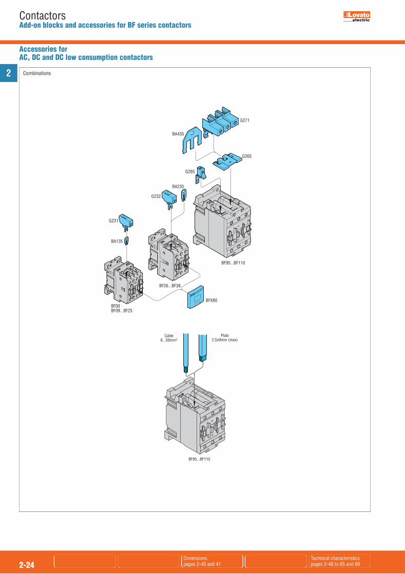
2
2-24Dimensionspages 2-40 and 41
Technical characteristics pages 2-48 to 65 and 69
ContactorsAdd-on blocks and accessories for BF series contactors
BF95...BF110
Cable6...50mm2
Plate2,5x9mm (max)
BF00BF09...BF25
G231
BA135
G232
BA235
G285
BA435
G265
G271
BF95...BF110
BF26...BF38
BFX80
Combinations
Accessories for AC, DC and DC low consumption contactors

2
2-25Dimensionspage 2-40
Wiring diagrams page 2-47
Technical characteristics pages 2-48...65
ContactorsAdd-on blocks and accessories for BF series contactors
Accessories for AC, DC and DC low consumption contactors
BFX50 02
BFX50 03
BFX31 01
BFX31 01BFX50 02BFX50 03
RF38
BFX50 02
BFX50 03
BFX50 00BFX50 01
BFX32 01
BFX32 01
BFX50 02
RF38
BFX31 31
BFX31 31
RF38
Connections for reversing contactors with contactors BF09...BF25
BFX50 00BFX50 01BFX31 02
BFX31 02
RF38
Connections for reversing contactors with contactors BF09...BF25 and mechanicalinterlock BFX50 00 or BFX50 01
Connections for reversing contactors with contactors BF26...BF38 Rigid star-delta starter assembly connecting kits for BF09-BF25 contactors
BFX32 32
BFX32 32
RF38
Rigid star-delta starter assembly connecting kits for BF26-BF38 (line-delta) andBF09-BF25 (star) contactors
BFX32 31
BFX32 31
RF38
Rigid star-delta starter assembly connecting kits for BF26-BF38 contactors

2
2-26Dimensionspages 2-42 and 43
Wiring diagrams page 2-47
Technical characteristics pages 2-66 to 69
ContactorsAdd-on blocks and accessories for B series contactors
� Only for B115-B145-B180-B250-B310-B400-B500-B630-B630 1000.� Not suitable for B630 1000-B1250-B1600 �.� For use with three-pole B630 1000, consult Customer Service for
information; see contact details on inside front cover.� Allowed distances see page 2-68.� For contactors B1250 and B1600, two G356 6 mechanical interlocks are
required.� Replace with the digit of the voltages if 50 or 60 Hz or with the letter C
followed by voltage if DC. The standard voltages are: – AC 50/60Hz 48 - 110...125 (indicate 110) - 220...240 (indicate 220) - 380...415 (indicate 380) – DC 48 - 110...125 (indicate 110) - 220...240 (indicate 220).It can be mounted only in contactors if predisposed for it. Consult Customer
Service for information; see contact details on inside front cover. Not suitable for B310 and B310 4.� Provided for one pole terminal only. Example: For three-pole contactors,
purchase 3 pieces for the upper terminals only or 6 pieces for all upper andlower terminals.
� Replace with the required alphanumeric symbol; each package contains 100pieces of the same symbol.
Order code Characteristics Max Qty Wt qty per. per contactor pk sg n° n° [kg] Auxiliary contacts. Faston terminals. Side mountinge. 11 G350� 2NO+1NC or 4 1 0.082 1NO+2NC reversible 11 G354� 1NO+1NC 4 1 0.078 Adapter. 11 G358 For fitting auxiliary 4 5 0.050 contacts BFX10..., with 2 contacts, G484..., G485..., G486... and G487 on contactors B115...B630 1000 described on p. 2-28 Mechanical interlock. 11 G355�� Side by side 1 1 0.026 11 G356 1�� One on top of other 1 1 0.120 11 G356 2�� One on top of other 1 1 0.126 11 G356 3�� One on top of other 1 1 0.132 11 G356 4�� One on top of other 1 1 0.140 11 G356 5�� One on top of other 1 1 0.146 11 G356 6�� One on top of other 1 1 0.150 Mechanical latch. 11 G495� For B115...B630 1 1 0.795
Add-on blocks
Order code Characteristics Qty Wt per pkg n° [kg] Power terminal protection. 11 G360� For contactor B115 6 0.026 11 G361� For contactors B145-B180 6 0.026 11 G363� For contactors B250-B310-B400 6 0.046 11 G527 For contactor B500 1 0.238 11 G528 For contactor B500 4 1 0.265 11 G529 For contactor B630 1 0.238 11 G530 For contactor B630 4 1 0.266 3 pole star connecting bars. 11 BA1595 For contactors B115-B145-B180 1 0.065 11 BA1721 For contactors B250-B310-B400 1 0.140 11 BA1846 For contactors B500-B630 1 0.341 2 pole bars for parallel arrangement. 11 BA1594 For contactors B115-B145-B180 1 0.095 11 BA1720 For contactors B250-B310-B400 1 0.149 11 BA1845 For contactors B500-B630 1 0.322 Terminal adapter. 11 G370 To transform Faston terminals 10 0.003 of auxiliary contacts and coils into screw terminals 11 G371 To transform both coil 5 0.022 Faston terminals into screw terminals
Accessories
Operational characteristics of auxiliary contactsType G350-G354IEC conventional free-air thermal A 16current IthIEC rated insulation voltage Ui V 690Terminals Faston 1-6.35x0.8 2-2.8x0.8Conductor section maximum(with 1 or 2 cables) flexible c/w lug mm2 2,5 AWG n° 14UL/CSA and IEC/EN 60947-5-1 AC A600designation DC P600Mechanical life (million) cycles 5
Type G495
Rated AC control circuit voltage AC (50/60Hz) V 48...480 DC V 48...480Power consumption with control in: AC VA 1500 DC W 1100Minimum energising: drop-out ms 40 pick-up ms 300Terminals Faston 1-6.3x0.8
Type G370-G371Tightening torque Nm 1 lbin 8.9Tool Type PH2Conductor section mm² 4(with 1 or 2 cables) AWG 10
Certifications and complianceCertifications obtained:Type UL CSA EAC CCC G350 � � �
G354 � � ––G355 –– � � ––G356 ... –– � � ––G360 –– � � ––G361 –– � � ––G362 –– � � ––G363 –– � � ––G370 –– � � ––
� Certified products.- UL Recognized for USA only (File E93601) as Auxiliary Devices -
Component. Products having this type of marking are intended for use as components of complete workshop-assembled
equipment.CSA - CSA certified for Canada only (File 54332) as Auxiliary Devices for
motor controllers.
Compliant with standards: IEC/EN 60947-1, IEC/EN 60947-4-1, UL508, CSA C22.2 n° 14; add-onauxiliary contacts also comply with: IEC/EN 60947-5-1.
11 G350 - 11 G354
11 G358
11 G360 - 11 G361 - 11 G363
11 G527 - 11 G528 - 11 G52911 G530
11 G370
11 G371
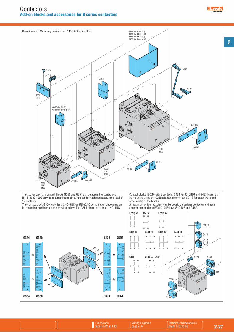
2
2-27Dimensionspages 2-42 and 43
Wiring diagrams page 2-47
Technical characteristics pages 2-66 to 69
ContactorsAdd-on blocks and accessories for B series contactors
B115B145B180
BA1594BA1595
B250B310B400
BA1721
BA1720
B500B630
BA1845
BA1846
G355
G527 (for B500 00)G528 (for B500 4 00)G529 (for B630 00)G530 (for B630 4 00)
G363
G370
G350G354
G360 (for B115)G361 (for B145-B180)
G356...
G371
Combinations: Mounting position on B115-B630 contactors
G354 G350
G354 G350
G350 G354
G350 G354
114
113
54
53
02
01
42
41
122
121
62
61
81
82
21
22
73
74
13
14
114
113
54
53
122
121
62
61
53
54
61
62
113
114
121
122
53
54
113
114
61
62
121
122
41
42
01
02
22
21
14
13
82
81
74
73
22
21
82
81
14
13
74
73
34
33
94
93
oror
oror
22
21
82
81
14
13
74
73
34
33
94
93
D
EF
G
C
BA
BFX10...
G484...
G485...G486...G487
G371 G358
G358
G358
G358
G485 ... G486 ... - G487
6658
6557
5668
5567
BFX10 2053 63
54 64
BFX10 0251 61
52 62
G484 21
53 61 73
54 62 74
G484 12
53 61 71
54 62 72
G484 03
51 61 71
52 62 72
G484 30
53 63 73
54 64 74
BFX10 1193 01
94 02
Contact blocks, BFX10 with 2 contacts, G484, G485, G486 and G487 types, canbe mounted using the G358 adapter, refer to page 2-18 for exact types andorder codes of the blocks. A maximum of four adapters can be possibly used per contactor and eachadapter can hold one BFX10, G484, G485, G486 and G487.
The add-on auxiliary contact blocks G350 and G354 can be applied to contactors B115-B630 1000 only up to a maximum of four pieces for each contactor, for a total of12 contacts. The contact block G350 provides a 2NO+1NC or 1NO+2NC combination depending onits mounting position; see the drawing delow. The G354 block consists of 1NO+1NC.
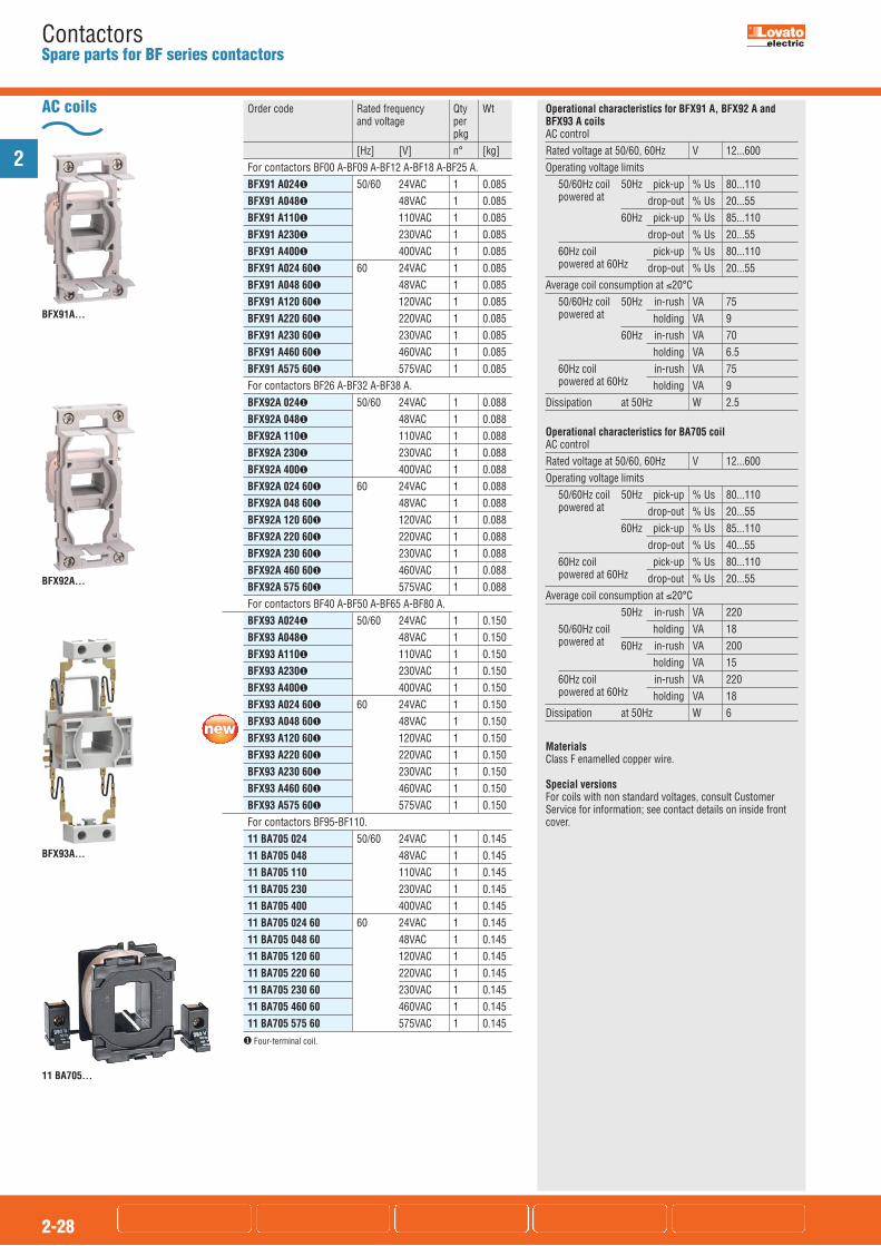
2
2-28
ContactorsSpare parts for BF series contactors
11 BA705...
Order code Rated frequency Qty Wt and voltage per pkg [Hz] [V] n° [kg] For contactors BF00 A-BF09 A-BF12 A-BF18 A-BF25 A. BFX91 A024� 50/60 24VAC 1 0.085 BFX91 A048� 48VAC 1 0.085 BFX91 A110� 110VAC 1 0.085 BFX91 A230� 230VAC 1 0.085 BFX91 A400� 400VAC 1 0.085 BFX91 A024 60� 60 24VAC 1 0.085 BFX91 A048 60� 48VAC 1 0.085 BFX91 A120 60� 120VAC 1 0.085 BFX91 A220 60� 220VAC 1 0.085 BFX91 A230 60� 230VAC 1 0.085 BFX91 A460 60� 460VAC 1 0.085 BFX91 A575 60� 575VAC 1 0.085 For contactors BF26 A-BF32 A-BF38 A. BFX92A 024� 50/60 24VAC 1 0.088 BFX92A 048� 48VAC 1 0.088 BFX92A 110� 110VAC 1 0.088 BFX92A 230� 230VAC 1 0.088 BFX92A 400� 400VAC 1 0.088 BFX92A 024 60� 60 24VAC 1 0.088 BFX92A 048 60� 48VAC 1 0.088 BFX92A 120 60� 120VAC 1 0.088 BFX92A 220 60� 220VAC 1 0.088 BFX92A 230 60� 230VAC 1 0.088 BFX92A 460 60� 460VAC 1 0.088 BFX92A 575 60� 575VAC 1 0.088 For contactors BF40 A-BF50 A-BF65 A-BF80 A. BFX93 A024� 50/60 24VAC 1 0.150 BFX93 A048� 48VAC 1 0.150 BFX93 A110� 110VAC 1 0.150 BFX93 A230� 230VAC 1 0.150 BFX93 A400� 400VAC 1 0.150 BFX93 A024 60� 60 24VAC 1 0.150 BFX93 A048 60� 48VAC 1 0.150 BFX93 A120 60� 120VAC 1 0.150 BFX93 A220 60� 220VAC 1 0.150 BFX93 A230 60� 230VAC 1 0.150 BFX93 A460 60� 460VAC 1 0.150 BFX93 A575 60� 575VAC 1 0.150 For contactors BF95-BF110. 11 BA705 024 50/60 24VAC 1 0.145 11 BA705 048 48VAC 1 0.145 11 BA705 110 110VAC 1 0.145 11 BA705 230 230VAC 1 0.145 11 BA705 400 400VAC 1 0.145 11 BA705 024 60 60 24VAC 1 0.145 11 BA705 048 60 48VAC 1 0.145 11 BA705 120 60 120VAC 1 0.145 11 BA705 220 60 220VAC 1 0.145 11 BA705 230 60 230VAC 1 0.145 11 BA705 460 60 460VAC 1 0.145 11 BA705 575 60 575VAC 1 0.145
AC coils
BFX91A...
Operational characteristics for BFX91 A, BFX92 A andBFX93 A coilsAC controlRated voltage at 50/60, 60Hz V 12...600Operating voltage limits
50/60Hz coil 50Hz pick-up % Us 80...110powered at drop-out % Us 20...55
60Hz pick-up % Us 85...110 drop-out % Us 20...55
60Hz coil pick-up % Us 80...110powered at 60Hz drop-out % Us 20...55
Average coil consumption at �20°C50/60Hz coil 50Hz in-rush VA 75powered at holding VA 9
60Hz in-rush VA 70 holding VA 6.5
60Hz coil in-rush VA 75powered at 60Hz holding VA 9
Dissipation at 50Hz W 2.5
Operational characteristics for BA705 coilAC controlRated voltage at 50/60, 60Hz V 12...600Operating voltage limits
50/60Hz coil 50Hz pick-up % Us 80...110powered at drop-out % Us 20...55
60Hz pick-up % Us 85...110 drop-out % Us 40...55
60Hz coil pick-up % Us 80...110powered at 60Hz drop-out % Us 20...55
Average coil consumption at �20°C50Hz in-rush VA 220
50/60Hz coil holding VA 18powered at 60Hz in-rush VA 200
holding VA 1560Hz coil in-rush VA 220powered at 60Hz holding VA 18
Dissipation at 50Hz W 6
BFX92A...
BFX93A...
� Four-terminal coil.
MaterialsClass F enamelled copper wire.
Special versionsFor coils with non standard voltages, consult CustomerService for information; see contact details on inside frontcover.

Order code Rated Qty Wt voltage per pkg [V] n° [kg] For contactors BF40 E-BF50 E-BF65 E-BF80 E. BFX93 E024 20...48V AC/DC 1 0.150 BFX93 E110 60...110V AC/DC 1 0.150 BFX93 E230 100...250V AC/DC 1 0.150 For contactors BF95 C...BF110 C. 11 BA911 12 12VDC 1 0.380 11 BA911 24 24VDC 1 0.380 11 BA911 48 48VDC 1 0.380 11 BA911 60 60VDC 1 0.380 11 BA911 110 110VDC 1 0.380 11 BA911 125 125VDC 1 0.380 11 BA911 220 220VDC 1 0.380
NOTE: No coil replacement for contactors BF00 D, BF09 D-BF38 D, BF00 L, BF09 L-BF38 L, is possible.
2
2-29
ContactorsSpare parts for BF series contactors
AC/DC and DC coils Operational characteristics for BFX93 E coilAC/DC control Rated voltage V 20...250Operating voltage pick-up % Us 80...110�limits: drop-out % Us 20...25�50/60 Hz coil powered ator in DC Average coil in-rush VA/W 60...125/50 cons. at �20°C
holding VA/W 1.7...2.3/1.5
Operational characteristics for BA911 coilDC control Rated voltage V 12...600Operating voltage pick-up % Us 80...110limits: drop-out % Us 10...25Average dissipation �20°C
W 15
in-rush/holding� For electronically controlled AC/DC coils 80% of Us min. and 110% of
Us max.� For electronically controlled AC/DC coils 20% of Us min. and 55% of
Us max.
11 BA911...
BFX93 E
MaterialsClass F enamelled copper wire.
Special versionsFor coils with non standard voltages, consult CustomerService for information; see contact details on inside frontcover.
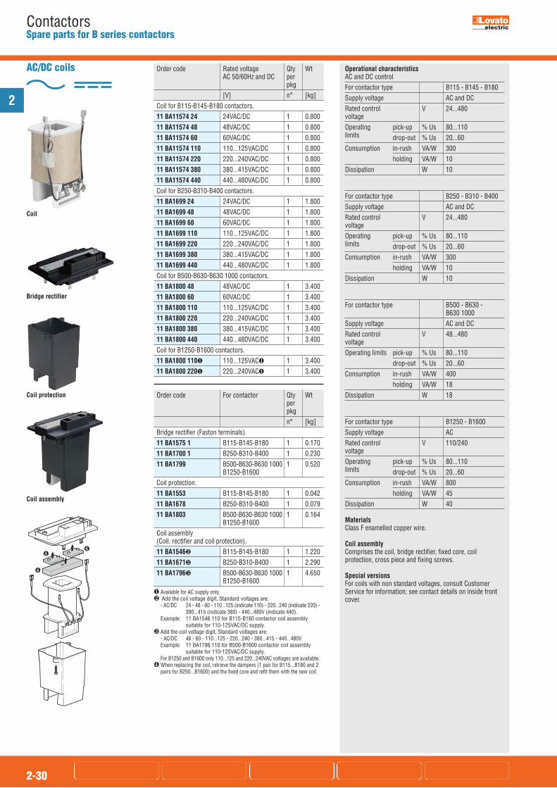
2
2-30
ContactorsSpare parts for B series contactors
Coil assembly
Coil protection
Bridge rectifier
Order code Rated voltage Qty Wt AC 50/60Hz and DC per pkg [V] n° [kg] Coil for B115-B145-B180 contactors. 11 BA11574 24 24VAC/DC 1 0.800 11 BA11574 48 48VAC/DC 1 0.800 11 BA11574 60 60VAC/DC 1 0.800 11 BA11574 110 110...125VAC/DC 1 0.800 11 BA11574 220 220...240VAC/DC 1 0.800 11 BA11574 380 380...415VAC/DC 1 0.800 11 BA11574 440 440...480VAC/DC 1 0.800 Coil for B250-B310-B400 contactors. 11 BA1699 24 24VAC/DC 1 1.800 11 BA1699 48 48VAC/DC 1 1.800 11 BA1699 60 60VAC/DC 1 1.800 11 BA1699 110 110...125VAC/DC 1 1.800 11 BA1699 220 220...240VAC/DC 1 1.800 11 BA1699 380 380...415VAC/DC 1 1.800 11 BA1699 440 440...480VAC/DC 1 1.800 Coil for B500-B630-B630 1000 contactors. 11 BA1800 48 48VAC/DC 1 3.400 11 BA1800 60 60VAC/DC 1 3.400 11 BA1800 110 110...125VAC/DC 1 3.400 11 BA1800 220 220...240VAC/DC 1 3.400 11 BA1800 380 380...415VAC/DC 1 3.400 11 BA1800 440 440...480VAC/DC 1 3.400 Coil for B1250-B1600 contactors. 11 BA1800 110� 110...125VAC� 1 3.400 11 BA1800 220� 220...240VAC� 1 3.400
Order code For contactor Qty Wt per pkg n° [kg] Bridge rectifier (Faston terminals). 11 BA1575 1 B115-B145-B180 1 0.170 11 BA1700 1 B250-B310-B400 1 0.230 11 BA1799 B500-B630-B630 1000 1 0.520 B1250-B1600 Coil protection. 11 BA1553 B115-B145-B180 1 0.042 11 BA1678 B250-B310-B400 1 0.079 11 BA1803 B500-B630-B630 1000 1 0.164 B1250-B1600 Coil assembly (Coil, rectifier and coil protection). 11 BA1546� B115-B145-B180 1 1.220 11 BA1671� B250-B310-B400 1 2.290 11 BA1796� B500-B630-B630 1000 1 4.650 B1250-B1600� Available for AC supply only.� Add the coil voltage digit. Standard voltages are: - AC/DC 24 - 48 - 60 - 110...125 (indicate 110) - 220...240 (indicate 220) - 380...415 (indicate 380) - 440...480V (indicate 440). Example: 11 BA1546 110 for B115-B180 contactor coil assembly
suitable for 110-125VAC/DC supply.� Add the coil voltage digit. Standard voltages are: - AC/DC 48 - 60 - 110...125 - 220...240 - 380...415 - 440...480V. Example: 11 BA1796 110 for B500-B1600 contactor coil assembly
suitable for 110-125VAC/DC supply. For B1250 and B1600 only 110...125 and 220...240VAC voltages are available.� When replacing the coil, retrieve the dampers (1 pair for B115...B180 and 2
pairs for B250...B1600) and the fixed core and refit them with the new coil.
AC/DC coils
Coil
Operational characteristicsAC and DC controlFor contactor type B115 - B145 - B180Supply voltage AC and DCRated control V 24...480voltage Operating pick-up % Us 80...110limits drop-out % Us 20...60Consumption in-rush VA/W 300 holding VA/W 10Dissipation W 10
For contactor type B250 - B310 - B400Supply voltage AC and DCRated control V 24...480voltage Operating pick-up % Us 80...110limits drop-out % Us 20...60Consumption in-rush VA/W 300 holding VA/W 10Dissipation W 10
For contactor type B500 - B630 - B630 1000Supply voltage AC and DCRated control V 48...480voltage Operating limits pick-up % Us 80...110 drop-out % Us 20...60Consumption in-rush VA/W 400 holding VA/W 18Dissipation W 18
For contactor type B1250 - B1600Supply voltage ACRated control V 110/240voltage Operating pick-up % Us 80...110limits drop-out % Us 20...60Consumption in-rush VA/W 800 holding VA/W 45Dissipation W 40
MaterialsClass F enamelled copper wire.
Coil assemblyComprises the coil, bridge rectifier, fixed core, coilprotection, cross piece and fixing screws.
Special versionsFor coils with non standard voltages, consult CustomerService for information; see contact details on inside frontcover.

2
2-31
ContactorsSpare parts for B series contactors
Order code For contactor Qty Wt per pkg n° [kg] Main contacts. 3 or 4 pole set complete with screws. BFX99 026T BF26 1 0.038 BFX99 026F BF26 T4 1 0.051 BFX99 032T BF32 1 0.070 BFX99 038T BF38 1 0.070 BFX99 038F BF38 T4 1 0.093 BFX99 040T BF40 1 0.095 BFX99 040F BF40T4 1 0.095 BFX99 050T BF50 1 0.095 BFX99 050F BF50 T4 1 0.095 BFX99 065T BF65 1 0.095 BFX99 065F BF65 T4 1 0.127 BFX99 080T BF80 1 0.100 BFX99 080F BF82 T4 1 0.130 11 G475 BF95 1 0.111 11 G476 BF110 1 0.111
Main contacts for BF contactors
BFX99...
11 G274... - 11 G275... - 11 G276... 11G475 - 11 G476
Special versionsFor non standard spare contact configurations, contactCustomer Service; see contact details on inside front cover.
NOTE: For B1250 and B1600 contactor spares, consultCustomer Service for information; see contact details oninside front cover.
Order code For contactor Qty Wt per pkg n° [kg] Main contacts. 3 or 4 pole set complete with Allen screws and key for contact replacement. 11 G380 B115 1 0.440 11 G380 4 B115 4 1 0.580 11 G381 B145 1 0.440 11 G381 4 B145 4 1 0.580 11 G382 B180 1 0.440 11 G382 4 B180 4 1 0.580 11 G383 B250 1 0.770 11 G383 4 B250 4 1 1.030 11 G385 B310 1 0.770 11 G385 4 B310 4 1 1.030 11 G384 B400 1 0.770 11 G384 4 B400 4 1 1.030 11 G525 B500 1 2.520 11 G525 4 B500 4 1 3.360 11 G526 B630 1 2.660 11 G526 4 B630 4 1 3.550 11 G537 B630 1000 1 2.660 11 G537 4 B630 1000 4 1 3.550 11 G538 B1250 24 1 5.040 11 G538 4 B1250 4 24 1 6.720 11 G539 B1600 24 1 5.320 11 G539 4 B1600 4 24 1 7.100 Arc chutes. 11 BA1588 B115-B145-B180 1 0.755 11 BA1589 B115 4-B145 4-B180 4 1 1.000 11 BA1713 B250-B310-B400 1 1.210 11 BA1714 B250 4-B310 4-B400 4 1 1.600 11 BA1838 B500-B630-B630 1000 1 1.910 11 BA1839 B500 4-B630 4- 1 2.490 B630 1000 4
11 G380... - 11 G381... - 11 G382...11 G383... - 11 G384... - 11 G385...11 G525... - 11 G526... - 11 G537...
Arc chute
Main contacts and arcchutes for B contactors

2
2-32
ContactorsDimensions [mm (in)]
BG... MINI-CONTACTORS WITH AC OR DC SUPPLY VOLTAGEBG... with screw terminals and RF...9 thermal overload relay
RF...9
44(1.73”)
89.2(3.51”)
3.2(0.12”)
7.6(0.30”)
34.9(1.37”)
57(2.24”)
50(1
.97”
)
58(2
.28”
)
4(0
.16”)
44(1.73”)
94.2
(3.7
1”)
BG...44
(1.73”)4.4
(0.17”)
8.5(0.33”)
9.7(0.38”)
4.4(0.17”)
8.5(0.33”)
8.5(0.33”)
34.9(1.37”)
57(2.24”)
50(1
.97”
)58
(2.2
8”)
4(0
.16”)
Ø1.4
(0.0
6”)
44(1.73”)
4.4(0.17”)
8.5(0.33”)
9.7(0.38”)
4.4(0.17”)
8.5(0.33”)
8.5(0.33”)
5.6(0.22”)
57(2.24”)
50(1
.97”
)
58 (2
.28”
)
53(2
.09”
)
Ø
44(1.73”)
4.4(0.17”)
8.5(0.33”)
9.7(0.38”)
4.4(0.17”)
8.5(0.33”)
8.5(0.33”)
34.9(1.37”)
57(2.24”)
50(1
.97”
)58
(2.2
8”)
4(0
.16”)
BGF...with Faston terminals
BGP... with rear PCB solder pins
BF26 T...A... - BF38 T...A... four poles61
(2.40”)
90(3
.54”
)
4.2(0
.17”)14.6(0.57”)
90(3.54”)
35(1.38”)
80(3
.15”
)
7.9(0.31”)
15.9(0.62”)
BF26 00A... - BF32 00A... - BF38 00A... three poles with RF...38 thermal overload relay
RF...38RF...38
45(1.77”)
81.5(3.21”)
7.9(0.31”)
90(3
.54”
)
4.2(0
.17”)
134.
8(5
.31”
)
14.6(0.57”)
90(3.54”)
35(1.38”)
80(3
.15”
)
7.9(0.31”)
14.6(0.57”)
BF40 T...A... - BF50 T...A... - BF65 T...A... - BF80 T...A... - BFD80 T4... four polesBF40 00A... - BF50 00A... - BF65 00A... - BF80 00A... three poles with RF82 thermal overload relay
55 (2.16”)9
(0.35”)18.5
(0.73”)
194
(7.6
4”)
114.5 (4.51”)
136
(5.3
5”)
125
(4.9
2”)
45 (1.77”)
110
(4.3
3”)
Ø4.5
(0.18
”)
BF... CONTACTORS WITH AC SUPPLY VOLTAGE
BF09T... A... - BF12T... A... - BF18T... A... four poles45
(1.77”)
81(3
.19”
)
4.2(0
.17”)6.2
(0.24”)10.9
(0.43”)80.7
(3.18”)
35(1.38”)
71(2
.79”
)
BF00 A... BF09 A... - BF12 A... - BF18 A... - BF25 A... three poles with RF...38 thermal overload relay
RF...38RF...38
45(1.77”)
81.2(3.20”)
7.9(0.31”)
81(3
.19”
)
4.2(0
.17”)
126
(4.9
6”)
6.2(0.24”)
10.9(0.43”)
14.6(0.57”)
80.7(3.18”)
35(1.38”)
71(2
.79”
)
� Recommended PCB drillings 1.7-2mm.
9(0.35”)
18(0.71”)
45 (1.77”)
110
(4.3
3”)
114.6 (4.51”)
136
(5.3
5”)
125
(4.9
2”)
Ø4.5
(0.18
”)
� BF80T2 82mm/3.23”

2
2-33
ContactorsDimensions [mm (in)]
BF95 00... - BF110 00... three poles with RF...95 3 thermal relay
RF...95 3RF...95 3
75 (2.95”)
6(0
.24”)
182
(7.1
6”)
23.5(0.92”)
14(0.55”) 113.5 (4.47”)
111 (4.37”)
55 (2.16”)
24.6(0.97”)
16.5(0.65”)
112
(4.4
1”)
124
(4.8
8”)
BF...CONTACTORS WITH DC SUPPLY VOLTAGE Control relaysBF09... - BF12... - BF18... - BF25...D and L three poles with RF...38 thermal overload relay
RF...38RF...38
45(1.77”)
4.2(0
.17”)
35(1.38”)
7.9(0.31”) 14.6
(0.57”)
10.9(0.43”)
6.2(0.24”)
126
(4.9
6”)
81.2(3.20”)
81(3
.19”
)
98.5(3.88”)
71(2
.79”
)
BF00...D and BF00...LBF09 T... - BF18 T... D and L four poles
10.9(0.43”)6.2
(0.24”)
45(1.77”)
Ø4.2(0
.17”)
35(1.38”)
71(2
.79”
)
81(3
.19”
)
98.5(3.88”)
BF26... - BF32... - BF38... D and L three poles with RF...38 thermal overload relay
RF...38RF...38
45(1.77”)
81.5(3.21”)
7.9(0.31”)
90(3
.54”
)
4.2(0
.17”)
134.
8(5
.31”
)
14.6(0.57”)
90(3.54”)
35(1.38”)
80(3
.15”
)
7.9(0.31”)
14.6(0.57”)
BF26 T... - BF38 T... D and L four poles
BF65 T4 E... - BF80 T4 E... four polesBF40 00E... - BF50 00E... - BF65 00E... - BF80 00E... three poles with RF82 thermal overload relay
55 (2.16”)9
(0.35”)18.5
(0.73”)
194
(7.6
4”)
114.5 (4.51”)
136
(5.3
5”)
125
(4.9
2”)
45 (1.77”)
110
(4.3
3”)
Ø4.5
(0.18
”)
73 (2.87”)9
(0.35”)18
(0.71”)45 (1.77”)
110
(4.3
3”)
114.6 (4.51”)
136
(5.3
5”)
125
(4.9
2”)
Ø4.5
(0.18
”)
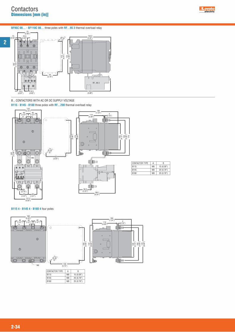
2
2-34
ContactorsDimensions [mm (in)]
B... CONTACTORS WITH AC OR DC SUPPLY VOLTAGEB115 - B145 - B180 three poles with RF...200 thermal overload relay
B115 4 - B145 4 - B180 4 four poles
M6
M8
BA
120(4.72”)
40(1.57”)
40(1.57”)
322
(12.
68”)
40(1.57”)
40(1.57”)
20(0.79”)
127.5(5.02”)
Ø7.5(0
.29”)
90(3.54”)
184(7.24”)
114(4.49”)
4(0.16”)
56.5(2.22”)
166.1(6.54”)
120
(4.7
2”)
150
(5.9
0”)
170
150
(5.9
0”)
170
(6.6
9”)
CONTACTOR TYPE A B
B115 M6 15 (0.59”)
B145 M8 20 (0.79”)
B180 M8 20 (0.79”)
M6
A B
120
(4.7
2”)
150
(5.9
0”)
170
(6.6
9”)
184(7.24”)
114(4.49”)
4(0.16”)
170
(6.6
9”)
150
(5.9
0”)
Ø7.5(0
.29”)
130(5.12”)
40(1.57”)
40(1.57”)
40(1.57”)
160(6.30”)
CONTACTOR TYPE A B
B115 M6 15 (0.59”)
B145 M8 20 (0.79”)
B180 M8 20 (0.79”)
BF95C 00... - BF110C 00... three poles with RF...95 3 thermal overload relay
RF...95 3
75(2.95”)
23.5(0.92”)
14(0.55”)
182
(7.1
6”)
24.6(0.97”)
16.5(0.65”)
6(0
.24”)
55(2.16”)
112
(4.4
1”)
124
(4.8
8”)
150.5(5.92”)
149.5(5.88”)
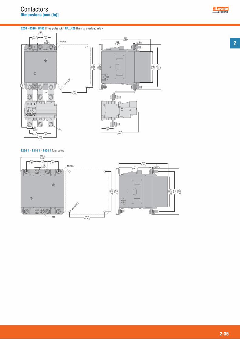
2
2-35
ContactorsDimensions [mm (in)]
B250 - B310 - B400 three poles with RF...420 thermal overload relay
B250 4 - B310 4 - B400 4 four poles
M8
M10
M10X35
145(5.71”)
47.5(1.87”)
47.5(1.87”)
Ø10 (0
.39”)
25(0.98”)
145(5.71”)
47.5(1.87”)
47.5(1.87”)
25(0.98”)
110(4.33”)
370
(14.
57”)
180
(7.0
9”)
204
(8.0
3”)
225(8.86”)
144(5.67”)
5(0.20”)
166.1(6.54”)
56.8(2.24”)
140
(5.5
1”)
179
(7.0
5”)
204
M8
192.5(7.58”)
47.5(1.87”)
47.5(1.87”)
Ø10 (0
.39”)
25(0.98”)
47.5(1.87”)
157.5(6.20”)
180
(7.0
9”)
204
(8.0
3”)
140
(5.5
1”)
179
(7.0
5”)
204
(8.0
3”)
225(8.86”)
144(5.67”)
5(0.20”)
M10X35
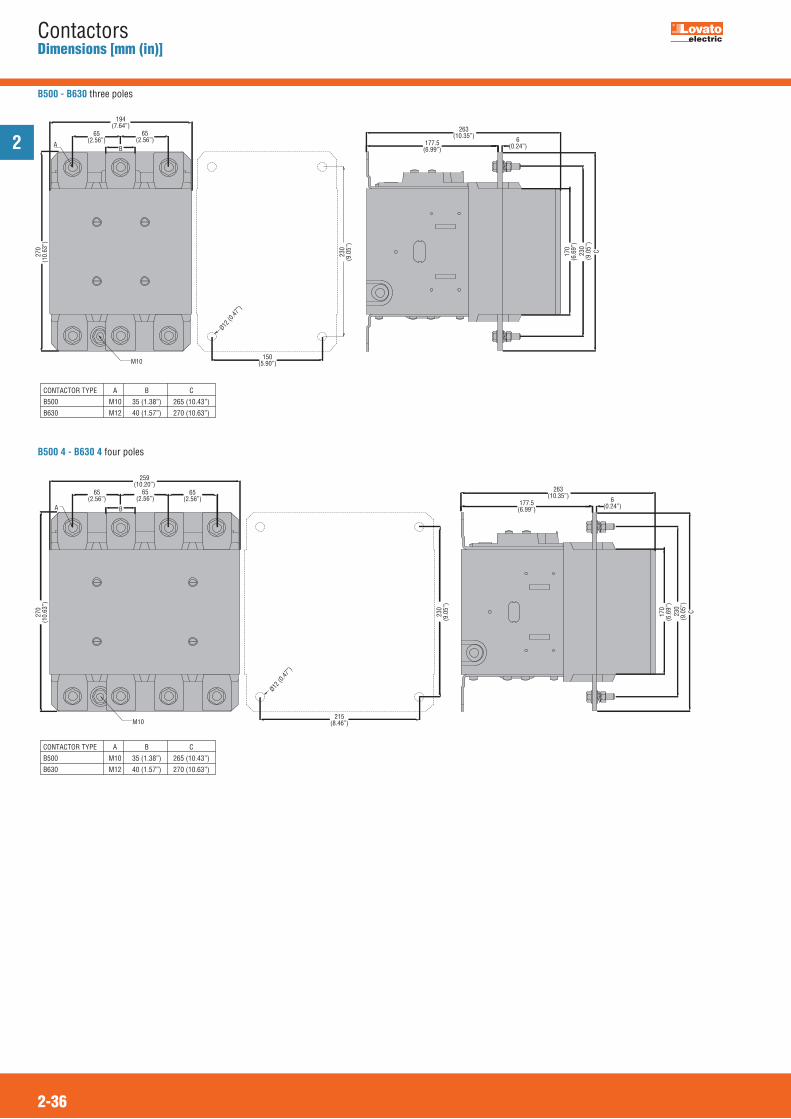
2
2-36
ContactorsDimensions [mm (in)]
B500 - B630 three poles
B500 4 - B630 4 four poles
A
M10
B
C
194(7.64”)
65(2.56”)
65(2.56”)
Ø12 (0
.47”)
150(5.90”)
270
(10.
63”)
230
(9.0
5”)
263(10.35”)
177.5(6.99”)
6(0.24”)
170
(6.6
9”)
230
(9.0
5”)
CONTACTOR TYPE A B C
B500 M10 35 (1.38”) 265 (10.43”)
B630 M12 40 (1.57”) 270 (10.63”)
CONTACTOR TYPE A B C
B500 M10 35 (1.38”) 265 (10.43”)
B630 M12 40 (1.57”) 270 (10.63”)
M10
A B
259(10.20”)
65(2.56”)
65(2.56”)
270
(10.
63”)
65(2.56”)
Ø12 (0
.47”)
215(8.46”)
230
(9.0
5”)
263(10.35”)
177.5(6.99”)
6(0.24”)
C170
(6.6
9”)
230
(9.0
5”)
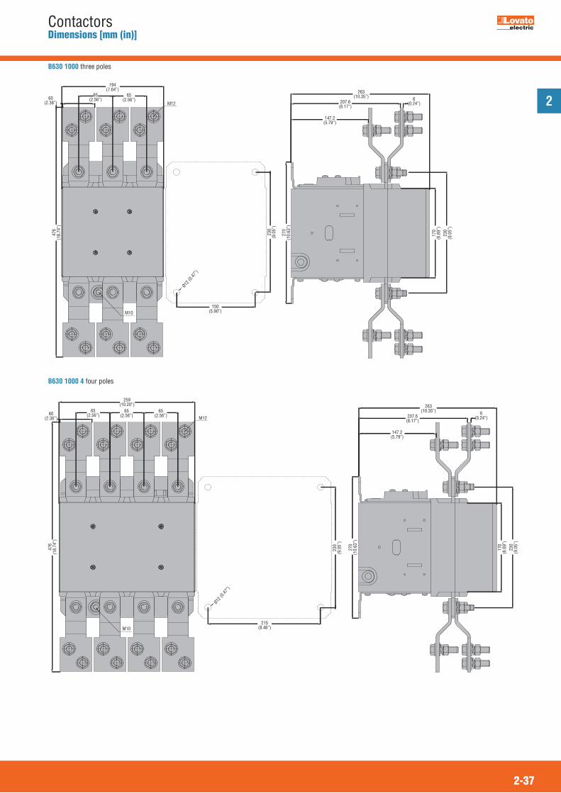
2
2-37
ContactorsDimensions [mm (in)]
B630 1000 three poles
M12
M10
Ø12 (0
.47”)
150(5.90”)
230
(9.0
5”)
194(7.64”)
60(2.36”)
65(2.56”)
65(2.56”)
476
(18.
74”)
270
(10.
63”)
170
(6.6
9”)
230
(9.0
5”)
263(10.35”)
207.6(8.17”)
6(0.24”)
147.2(5.79”)
B630 1000 4 four poles
M12
M10
259(10.20”)
60(2.36”)
65(2.56”)
65(2.56”)
476
(18.
74”)
65(2.56”)
Ø12 (0
.47”)
215(8.46”)
230
(9.0
5”)
270
(10.
63”)
263(10.35”)
207.6(8.17”)
6(0.24”)
147.2(5.79”)
170
(6.6
9”)
230
(9.0
5”)
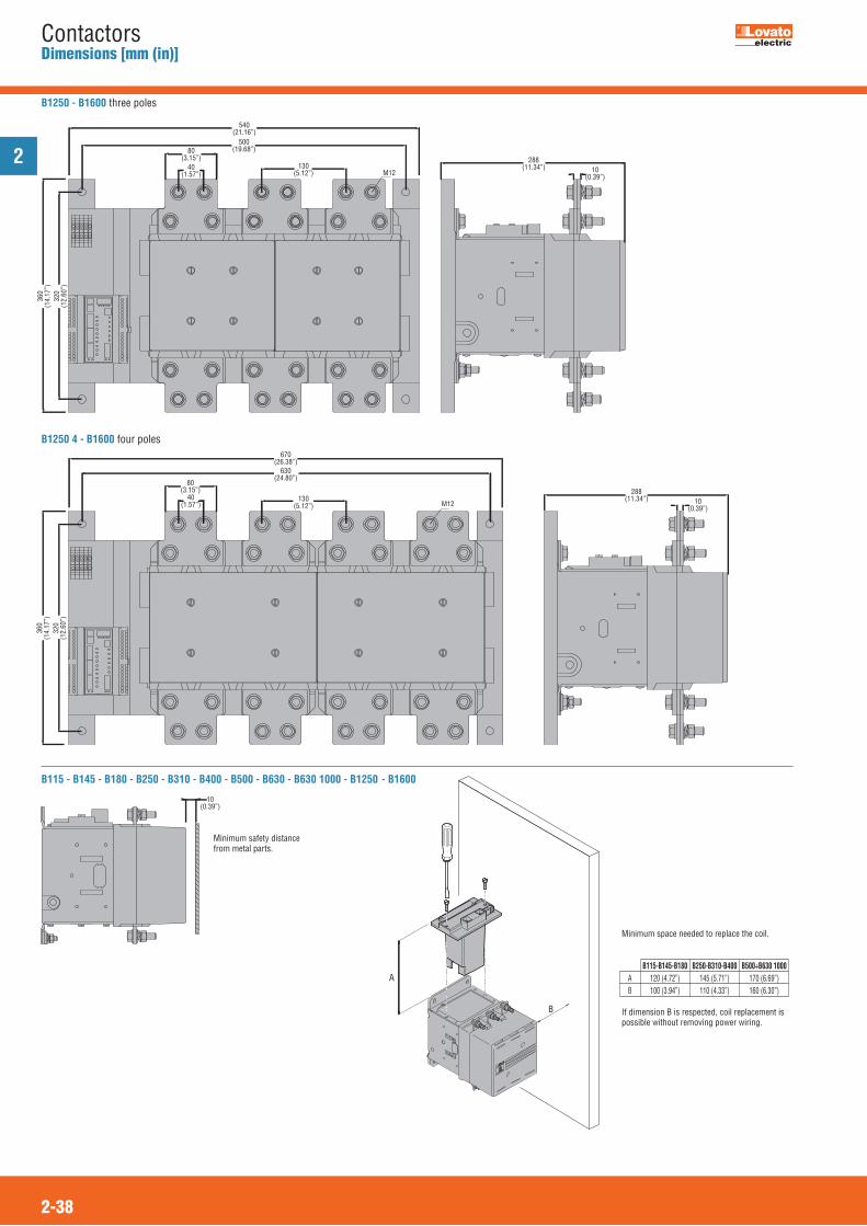
2
2-38
ContactorsDimensions [mm (in)]
B115 - B145 - B180 - B250 - B310 - B400 - B500 - B630 - B630 1000 - B1250 - B1600
10(0.39”)
A
B
Minimum space needed to replace the coil.
If dimension B is respected, coil replacement ispossible without removing power wiring.
B115-B145-B180 B250-B310-B400 B500÷B630 1000 A 120 (4.72”) 145 (5.71”) 170 (6.69”) B 100 (3.94”) 110 (4.33”) 160 (6.30”)
B1250 - B1600 three poles
540(21.16”)
500(19.68”)
M12
288(11.34”) 10
(0.39”)
80(3.15”)
40(1.57”)
130(5.12”)
360
(14.
17”)
320
(12.
60”)
M12
670(26.38”)
630(24.80”)
80(3.15”)
40(1.57”)
130(5.12”)
360
(14.
17”)
320
(12.
60”)
288(11.34”) 10
(0.39”)
B1250 4 - B1600 four poles
Minimum safety distance from metal parts.
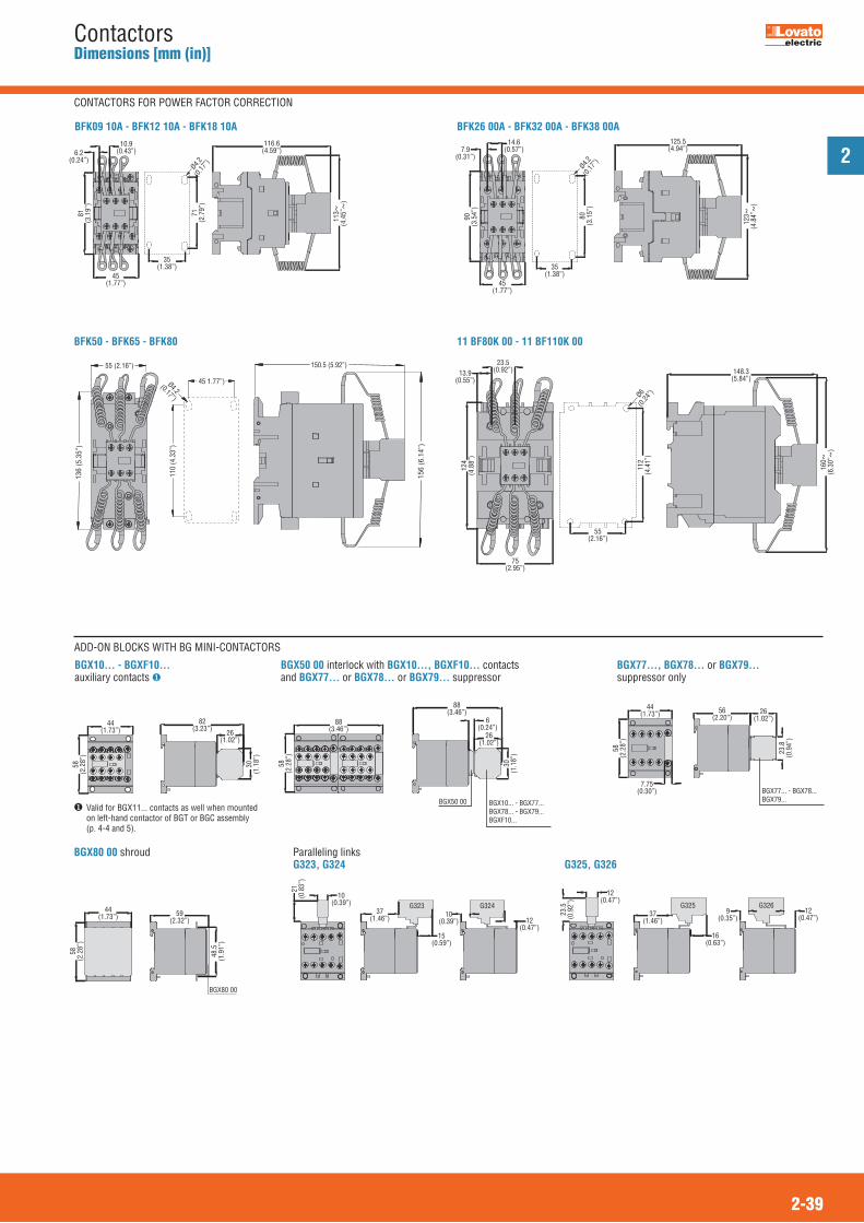
2
2-39
ContactorsDimensions [mm (in)]
ADD-ON BLOCKS WITH BG MINI-CONTACTORS
BFK09 10A - BFK12 10A - BFK18 10A
45(1.77”)
Ø4.2(0
.17”)
35(1.38”)
10.9(0.43”)6.2
(0.24”)
71(2
.79”
)
81(3
.19”
)
113~
(4.4
5”~
)
116.6(4.59”)
BFK26 00A - BFK32 00A - BFK38 00A
45(1.77”)
14.6(0.57”)7.9
(0.31”)
90(3
.54”
)
Ø4.2(0
.17”)
35(1.38”)
80(3
.15”
)
123~
(4.8
4”~
)
125.5(4.94”)
11 BF80K 00 - 11 BF110K 00
75(2.95”)
23.5(0.92”)13.9
(0.55”)
124
(4.8
8”)
Ø6(0
.24”)
55(2.16”)
112
(4.4
1”)
160~
(6.3
0”~
)
148.3(5.84”)
BGX10... - BGXF10...auxiliary contacts �
44(1.73”)
82(3.23”) 26
(1.02”)
58(2
.28”
)
30(1
.18”
)
Paralleling linksG323, G324
G323 G324
21(0
.83”
)
10(0.39”)
37(1.46”) 10
(0.39”)
15(0.59”)
12(0.47”)
G325, G326
G325 G326
23.5
(0.9
2”)
12(0.47”)
37(1.46”)
12(0.47”)
9(0.35”)
16(0.63”)
BGX80 00 shroud
BGX80 00
58(2
.28”
)
44(1.73”) 59
(2.32”)
48.5
(1.9
1”)
BGX50 00 interlock with BGX10..., BGXF10... contactsand BGX77... or BGX78... or BGX79... suppressor
BGX10... - BGX77...BGX78... - BGX79...BGXF10...
BGX50 00
88(3.46”)
58(2
.28”
)
88(3.46”)
26(1.02”)
30(1
.18”
)
6(0.24”)
BGX77..., BGX78... or BGX79...suppressor only
BGX77... - BGX78... BGX79...
44(1.73”)
58(2
.28”
)
7.75(0.30”)
56(2.20”)
26(1.02”)
23.8
(0.9
4”)
� Valid for BGX11... contacts as well when mountedon left-hand contactor of BGT or BGC assembly(p. 4-4 and 5).
CONTACTORS FOR POWER FACTOR CORRECTION
BFK50 - BFK65 - BFK80
45 1.77”)Ø4.2
(0.17”)
110
(4.3
3”)
55 (2.16”)
136
(5.3
5”)
150.5 (5.92”)
156
(6.1
4”)
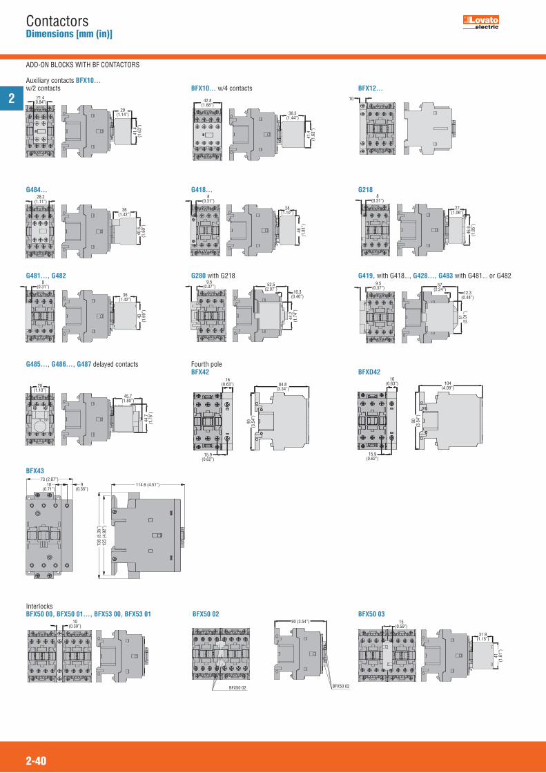
2
2-40
ContactorsDimensions [mm (in)]
21.4(0.84”)
29(1.14”)
41.4
(1.6
3”)
Auxiliary contacts BFX10...w/2 contacts
42.8(1.68”)
36.5(1.44”)
41.4
(1.6
3”)
BFX10... w/4 contacts
28.2(1.11”)
36(1.42”)
40.6
(1.6
0”)
G484...8
(0.31”)
28(1.10”)
46(1
.81”
)
G418...8
(0.31”)
27(1.06”)
46.9
(1.8
5”)
G218
8(0.31”)
36(1.42”)
43(1
.69”
)
G481..., G4829.5
(0.37”) 52.5(2.07”)
44.2
(1.7
4”)
10.3(0.40”)
G280 with G2189.5
(0.37”)57
(2.24”)
51(2
.01”
)
12.3(0.48”)
G419, with G418..., G428..., G483 with G481... or G482
28(1.10”)
45.7(1.80”)
44.7
(1.7
6”)
G485..., G486..., G487 delayed contacts
114.6 (4.51”)
136
(5.3
5”)
125
(4.9
2”)
73 (2.87”)9
(0.35”)18
(0.71”)
BFX43
84.8(3.34”)
16(0.63”)
90(3
.54”
)
15.9(0.62”)
Fourth poleBFX42
104(4.09”)
16(0.63”)
90(3
.54”
)
15.9(0.62”)
BFXD42
10
BFX12...
10(0.39”)
InterlocksBFX50 00, BFX50 01..., BFX53 00, BFX53 01
90 (3.54”)
BFX50 02BFX50 02
BFX50 0215
(0.59”)
31.9(1.15”)
41(1
.61”
)
BFX50 03
ADD-ON BLOCKS WITH BF CONTACTORS
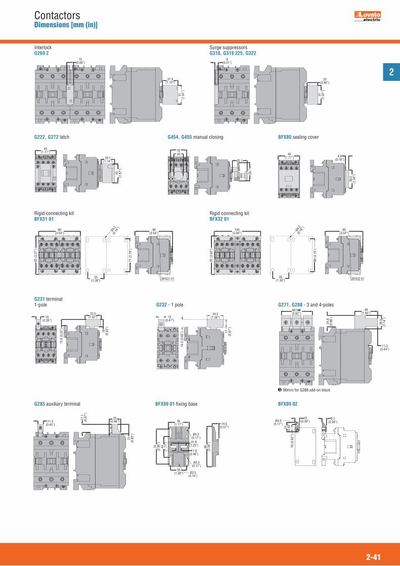
2
2-41
ContactorsDimensions [mm (in)]
45(1.77”)
29.1(1.14”)
40(1
.57”
)
G222, G272 latch
90(3.54”)
90(3.54”)
35(1.38”)
Ø4.2
(0.16
”)
83 (3
.27”
)
71 (2
.79”
)
BFX31 01
Rigid connecting kitBFX31 01
100(3.94”)
90(3.54”)
92 (3
.62”
)
BFX32 0135(1.38”)
Ø4.2(0
.16”)
80 (3
.15”
)
Rigid connecting kitBFX32 01
3520
32.1
38.7
G454, G455 manual closing
49(1.93”)
66.5❸(2.62”)
28.9
(1.1
4”)
24.8
(0.9
8”)
11.3(0.44”)
G271, G288 - 3 and 4-poles
11.5(0.45”)
25(0.98”)
17.1
(0.6
7”)
21(0
.83”
)
45(1.77”)
31.8(1.25”)
11.6(0.46”)
35(1.38”)
14.5(0.57”)
45(1
.77”
)
75(2
.95”
)
86(3
.38”
)
Ø4.3(0.17”)
Ø4.3(0.17”)
Ø3.5(0.14”)
BFX89 01 fixing base
10(0.39”)Ø4.3
(0.17”)
16 (0
.63”
)
9.7(0.38”)
21(0
.83”
)
BFX89 02
45(1.77”) 4.5
(0.18”)
39.2
(1.5
4”)
BFX80 sealing cover
10(0.39”)
33.5(1.32”)
16(0
.63”
)
13.6
(0.5
3”)
G231 terminal1-pole
12(0.47”)
34.5(1.36”)
17(0
.67”
)
16.5
(0.6
5”)
G232 - 1 pole
� 90mm for G288 add-on block
G285 auxiliary terminal
31.9(1.15”)
41(1
.61”
)
15(0.59”)
InterlockG269 2
23(0.90”)
41(1
.61”
)
8(0.31”)
Surge suppressorsG318, G319 225, G322

2
2-42
ContactorsDimensions [mm (in)]
185(7.28”)
117
(4.6
1”)
G527, G529
ADD-ON BLOCKS WITH B CONTACTORS
14.5(0.57”) 111.5
(4.39”)
60.6
(2.3
8”)
Auxiliary contacts G350, G354
29.8(1.17”)
❶
G356...
30(1.18”)
G358 adapter
15(0.59”)
G355 interlocks
� For dimensions, refer to page 2-68.
102(4.01”)
50(1.97”)
31.9(1.25”)
68(2
.68”
)
Terminal protection G360, G361
127.5(5.02”)
56.5(2.22”)
35.2(1.38”)
96.7
(3.8
1”)
Terminal protectionG363
167(6.57”)
83(3.27”)
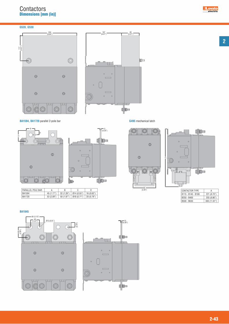
2
2-43
ContactorsDimensions [mm (in)]
250(9.84”)
167(6.57”)
117
(4.6
1”)
83(3.27”)
A
85(3.35”)
E1 E2
CONTACTOR TYPE AB115 - B145 - B180 221 (8.70”)B250 - B400 255 (8.86”)B500 - B630 300 (11.81”)
G528, G530
G495 mechanical latch
A
B
CD
5(0.20”)
BA1594, BA1720 parallel 2-pole bar
10(0.39”)
80 (3.15”)40
(1.57”) Ø13 (0.51”)
65(2
.56”
)
20(0
.79”
)
BA1845
PARALLEL POLE BAR A B C DBA1594 45 (1.77”) 32 (1.26”) Ø14 (0.55”) 16 (0.63”)BA1720 53 (2.09”) 50 (1.97”) Ø18 (0.71”) 20 (0.79”)

2
2-44
ContactorsWiring diagrams
THREE-POLE CONTACTORS IN ACBG06 A - BG09 A - BGF09 A - BGP09 A - BG12 ABF09 A - BF12 A - BF18 A - BF25 A
BF26 A - BF32 A - BF38 ABF40 A - BF50 A - BF65 A BF80 A - BF95 - BF110BF115...B630
1A1 3
2A2 4
5
6
13L1 L2 L3
14T1 T2 T3
1A1 3
2A2 4
5
6
L1 L2 L3
T1 T2 T3
...10
1A1 3
2A2 4
5
6
21L1 L2 L3
22T1 T2 T3
...01
THREE-POLE CONTACTORS IN DC (AC/DC for BF40E...BF80E)BG06 D - BG09 D - BGF09 D - BGP09 D - BG12 DBG06 L - BG09 L - BGF09 L - BGP09 L - BG12 L
1A1 3
2A2 4
5
6
13L1 L2 L3
14T1 T2 T3
...10
1A1 3
2A2 4
5
6
21L1 L2 L3
22T1 T2 T3
...01
BF09 D - BF12 D - BF18 D - BF25 DBF09 L - BF12 L - BF18 L - BF25 L
1 3
2 4
5
6
13L1 L2 L3
14T1 T2 T3
A1
A2
...10
1 3
2 4
5
6
21L1 L2 L3
22T1 T2 T3
A1
A2
...01
B1250 24 - B1600 24... �
L1 L2 L3
T1 T2 T3
A1
A2
� The input electronic circuitof the contactor coil isdesigned and testedaccording to IEEEC 62.41standards and canwithstand a 10kV impulsevoltage (1.2/50μs) with 50Joule energy.
The use of an auxiliaryreduced voltage transformeris recommended for highervalues.
BF26 D - BF32 D - BF38 DBF26 L - BF32 L - BF38 L
1 3
2 4
5
6
L1 L2 L3
T1 T2 T3
A1
A2
BF95C - BF110C
1A1 3
2A2 4
5
6
L1 L2 L3
T1 T2 T3
BF40 E - BF50 E - BF65 EBF80 E
1A1 3
2A2 4
5
6
L1 L2 L3
T1 T2 T3
CONTACTORS FOR POWER FACTOR CORRECTIONBFK09 A - BFK12 A - BFK18 ABFK26 A - BFK32 A - BFK38 A - BFK50 - BFK65 - BFK80 - 11 BF80K - 11 BF110K
1
A1
3
2
A2
4
5
6
13
L1 L2 L3
14
T1 T2 T3
� Auxiliary contact 13-14 is found on BFK09 A - BFK12 A - BFK18 A types only.
�

2
2-45
ContactorsWiring diagrams
FOUR-POLE CONTACTORS IN AC WITH 2NO AND 2NC POLESBG09 T2 A
NOA1 NC
2A2 R2
NC
R4
1 R1 R3NO
4
3
BF09 T2 A - BF18 T2 A - BF26 T2 A - BF38 T2 ABF80 T2 A
NCA1 NO
R2A2 2
NO
4
R1 1 3NC
R4
R3
WITH NC FOUR-POLESBF18 T0 A - BF26 T0 A
NCA1 NC
R2A2 R4
NC
R6
R1 R3 R5NC
R8
R7
FOUR-POLE CONTACTORS IN DC (AC/DC for BF80T2E) WITH 2NO AND 2NC POLESBG09 T2 D
NOA1 NC
2A2 R2
NC
R4
1 R1 R3NO
4
3
BF18 T2 D - BF26 T2 D - BF38 T2 D - BF80 T2 EBF18 T2 L - BF26 T2 L - BF38 T2 L
NC NO
R2 2
NO
4
R1 1 3NC
R4
R3A1
A2
WITH NC FOUR-POLES BF18 T0 D - BF26 T0 DBF18 T0 L
NC NC
R2 R4
NC
R6
R1 R3 R5NC
R8
R7A1
A2
BF80 T2 E
NC NC
R2 R4
NC
R6
R1 R3 R5NC
R8
R7A1
A2
CONTROL RELAY IN ACBG00 40 A - BGF00 40 ABF00 40 A
13A1 23
14A2 24
33
34
43
44
BG00 31 A - BGF00 31 ABF00 31 A
13A1 21
14A2 22
33
34
43
44
BG00 22 A - BGF00 22 ABF00 22 A
13A1 21
14A2 22
31
32
43
44
BF00 04 A
11A1 21
12A2 22
31
32
41
42
CONTROL RELAY IN DCBG00 40 D - BGF00 40 DBG00 40 L - BGF00 40 L
13A1 23
14A2 24
33
34
43
44
BG00 31 D - BGF00 31 DBG00 31 L - BGF00 31 L
13A1 21
14A2 22
33
34
43
44
BG00 22 D - BGF00 22 DBG00 22 L - BGF00 22 L
13A1 21
14A2 22
31
32
43
44
BF00 40 DBF00 40 L
13 23
14 24
33
34
43
44
A1
A2
BF00 31 DBF00 31 L
13 21
14 22
33
34
43
44
A1
A2
BF00 22 DBF00 22 L
13 21
14 22
31
32
43
44
A1
A2
BF00 04 DBF00 04 L
11 21
12 22
31
32
41
42
A1
A2
FOUR-POLE CONTACTORS IN ACBG09 T4 A - BGF09 T4 A - BGP09 T4 ABF09 T4 A - BF38 T4 ABF50 T4 A - BF65 T4 A - BF80 T4 ABFD80 T4 A - BFD80 40B115...B630 4
1A1 3
2A2 4
5
6
L1 L2 L3
T1 T2 T3
7
8
L4
T4
B1250 4 - B1600 4
L1 L2 L3
T1 T2 T3
L4
T4
A1
A2
FOUR-POLE CONTACTORS IN DC (AC/DC for BF40E...BF80E)BG09 T4 D - BGF09 T4 D - BGP09 T4 D
1A1 3
2A2 4
5
6
L1 L2 L3
T1 T2 T3
7
8
L4
T4
BF09 T4 D - BF38 T4 DBF09 T4 L - BF38 T4 L
1 3
2 4
5
6
L1 L2 L3
T1 T2 T3
7
8
L4
T4
A1
A2
BF65 T4 E - BF80 T4 EBFD80C 40
1A1 3
2A2 4
5
6
L1 L2 L3
T1 T2 T3
7
8
L4
T4

2
2-46
ContactorsWiring diagrams
ADD-ON BLOCKS FOR BG MINI-CONTACTORSAuxiliary contactsBGX10 02BGXF10 02
Special auxiliary contacts
Rigid connections
Surge suppressor
51 61
52 62
BGX10 11BGXF10 11
53 61
54 62
BFX10 11
53
54
61
62
BFX10 20
53
54
63
64
BGX10 20BGXF10 20
53 63
54 64
BGX77...~
~
SMX90 21
1A1 3
2A2
A1
A24
5
6
L11L1L2
3L2L3
5L3
T1 T2 T32 4 6T1 T2 T3
A1
A2
1L1
3L2
5L3
2 4 6T1 T2 T3
SMX90 22
1A1 3
2A2
A1
A24
5 11
6 12
11
12
L11L1L2
3L2L3
5L3
T1 T2 T32 4 6T1 T2 T3
BGX78...+
+
--
–
BGX11 1151
52
63
64
BGX11 2273 83
74 84
51 61
52 62
BGX79...~
~
BGX10 04BGXF10 0451 61 71 81
52 62 72 82
G484 30
53
54
63
64
73
74
G484 21
53
54
61
62
73
74
G484 12
53
54
61
62
71
72
G484 03
51
52
61
62
71
72
BGX10 13BGXF10 13
53 61 71 81
54 62 72 82
BGX10 22BGXF10 22
53 63 71 81
54 64 72 82
BGX10 31BGXF10 31
53 63 73 81
54 64 74 82
BGX10 40BGXF10 40
53 63 73 83
54 64 74 84
ADD-ON BLOCKS FOR BF CONTACTORSAuxiliary contactsBFX10 02
51
52
61
62
BFX10 0451 61 71 81
52 62 72 82
BFX10 1353 61 71 81
54 62 72 82
BFX10 2253 837161
54 847262
BFX10 3153 837361
54 74 8462
BFX10 4053 63 73 83
54 64 74 84
BFX10 11 1153 877561
54 887662
Auxiliary contactG218
9103
0294
9204
0193
9103
0294
9204
019391
03
0294
9204
0193
9103
0294
9204
0193
The termination of the G218 auxiliary contact has more than one numbering due to the fact that the block can assume various mounting positions.See the numbering in boldface for a correct interpretation.
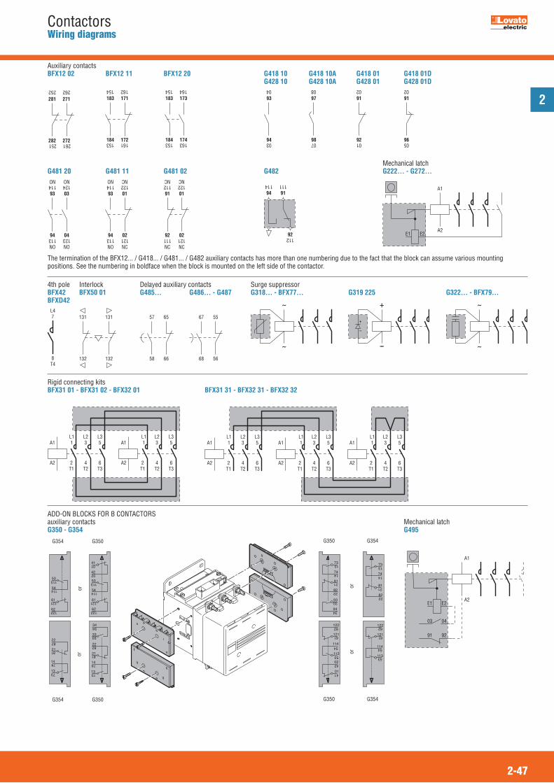
2
2-47
ContactorsWiring diagrams
A1
A2E1 E2
03 04
91 92
G354 G350
G354 G350
G350 G354
G350 G354
114
113
54
53
02
01
42
41
122
121
62
61
81
82
21
22
73
74
13
14
114
113
54
53
122
121
62
61
53
54
61
62
113
114
121
122
53
54
113
114
61
62
121
122
41
42
01
02
22
21
14
13
82
81
74
73
22
21
82
81
14
13
74
73
34
33
94
93
oror
oror
22
21
82
81
14
13
74
73
34
33
94
93
BFX31 01 - BFX31 02 - BFX32 01
1A1 3
2A2
A1
A24
5
6
L11
L1L23L2L3
5L3
T1 T2 T32 4 6T1 T2 T3
BFX31 31 - BFX32 31 - BFX32 32
1A1 3
2A2
A1
A24
5
6
L11L1L2
3L2L3
5L3
T1 T2 T32 4 6T1 T2 T3
A1
A2
1L1
3L2
5L3
2 4 6T1 T2 T3
ADD-ON BLOCKS FOR B CONTACTORSauxiliary contactsG350 - G354
Mechanical latchG495
BFX12 11
183
184
171
172161153
162154
BFX12 20
183
184
173
174163153
164154
Auxiliary contactsBFX12 02
Delayed auxiliary contacts
Mechanical latch
Interlock4th pole
281
282
271
272
262252
261251
G418 10G428 10
93
9403
04
G418 10AG428 10A
97
9807
08
G418 01G428 01
91
9201
02
G418 01DG428 01D
91
9605
02
The termination of the BFX12... / G418... / G481... / G482 auxiliary contacts has more than one numbering due to the fact that the block can assume various mountingpositions. See the numbering in boldface when the block is mounted on the left side of the contactor.
G481 20
93
94
03
124114
123113
NONO
04
NO NO
G481 11
93
94
01
122114
121113
NCNO
02
NO NC
G481 02
91
92
01
122112
121111
NCNC
02
NC NC
G482
112
91
92
111
94
114
Surge suppressor
Rigid connecting kits
G485...
57
58
65
66
G486... - G487
67
68
55
56
BFX42BFXD42
7
8
L4
T4
BFX50 01
131
132
131
132
G222... - G272...
A1
A2E1 E2
G318... - BFX77...
~
~
G319 225
+
+
--
–
G322... - BFX79...
~
~

2
2-48
ContactorsTechnical characteristics
MOUNTING POSITION OF CONTACTORSON VERTICAL PLANEThe performances given in this catalogue have been established with contactorsmounted on a vertical plane with line terminals facing upwards and load terminalsfacing downwards.All contactors can be mounted with a ± 30° inclination to thevertical axis of the contactor without any derating.
For BF series contactors, this inclination can reach ± 90°, that is with the terminalsare facing towards left and right.For BG mini-contactors:– Position A, with coil terminals A1-A2 facing downwards, is not recommended.– The position with coil terminals A1-A2 facing upwards is not recommended for
mini-contactors with NC contacts.
ON VERTICAL PLANE WITH 30° INCLINATIONAll contactors can be mounted on a plane which varies in respect to the vertical upto ± 30° angle.On the average, a 5% increase of the minimum pick-up voltage in -30° position canbe noted.
This inclination is greater than the one prescribed by main naval registers.
±30°�
±30°�
ON HORIZONTAL PLANE (FOR BF SERIES CONTACTORS)Considerable performance variations can be noted.It is necessary to check the two possible mounting positions:– when the contactor is energised, the movable equipment moves upwards.– when the contactor is energised, the movable equipment moves downwards.In the first case, it is difficult to close the contactor while in the second, to open it.
Our Customer Service (Tel. 035 4282422;E-mail: [email protected]) can provide furtherinformation concerning operational performance ofcontactors mounted on a horizontal plane.
DYNAMIC TYPE TESTSOur contactors have sustained dynamic testing, with contactor mounting positionrotated ± 22.5° in respect to the three orthogonal axes.
The variables which could influence the contactor performance, in addition to thetwo mounting positions, are:– type of contactor– type of control– contact configuration– number and type of add-on blocks– permissible tolerance of auxiliary voltage variation– ambient temperature.NOTE: Position B is not recommendable.
Pos. AA2
A1

2
2-49
ContactorsTechnical characteristics
100050
060
0
300
10025 3010
0.1
0.2
0.3
0.5
1
2
3
5
10
2 3 5
12
20
38 50
MIL
LION
CYC
LES
BF09
BF12
BF18
BF25
BF26
BF32
BF38
BF50
BF65
BF80
BF95
B115
B145
B180
B250
B310
B400
B500
B630
[A]
200
400
420
15032 65 95 185
250
520
630
110
31096 80
BG12BG06BG09
BF11
0
18 26
BF40
40
ELECTRICAL IEC LIFE FOR MOTOR CONTROL AC3 �440VElectrical life of contactors
IEC UTILISATION CATEGORY AC3 UL/CSA DUTY FOR AC MOTOR SWITCHINGPOLE CHARACTERISTICS MAGNETIC MOTOR CONTROLLERSSquirrel-cage induction motors; breaking at rated motor current. Three-phase AC induction motors; breaking at
rated motor current.MAXIMUM IEC OPERATIONAL POWER at ambient temperature �55°C. UL/CSA RATINGS at ambient temperature �55°C
Contactor IEC operational IEC operational power Maximum horsepower ratings (60Hz)type current Three phase (Ue �440V) 220/230V 380/400V 415V 440V 500V 660/690V 1000V 200-208V 240V 480V 600V [A] [kW] [kW] [kW] [kW] [kW] [kW] [kW] [HP] [HP] [HP] [HP]BG06 6 1.5 2.2 2.4 2.5 3 3 -- 1½ 2 3 3 BG09 9 2.2 4.0 4.3 4.5 5 5 -- 2 3 5 5 BG12 12 3.2 5.7 6.2 5.5 5 5 -- 3 3 7½ 10 BF09 9 2.2 4.2 4.5 4.8 5.5 7.5 -- 3 3 5 7 ½ BF12 12 3.2 5.7 6.2 6.2 7.5 10 -- 5 5 7½ 10 BF18 18 4 7.5 9 9 10 10 -- 5 5 10 15 BF25 25 7.0 12.5 13.4 13.4 15 18 -- 7½ 7½ 15 15 BF26 26 7.3 13 14 14 15.6 18.5 -- 7½ 7½ 15 20 BF32 32 8.8 16 17 17 20 22 -- 10 10 20 25 BF38 38 11 18.5 18.5 18.5 20 22 -- 10 15 30 30 BF40 40 11 18.5 22 22 22 30 18 10 15 30 40BF50 50 15 22 30 30 30 37 22 10 15 30 40 BF65 65 18.5 30 37 37 37 45 30 20 25 50 60 BF80 80 22 45 45 45 55 75 37 25 30 60 75 BF95 95 27.6 50 55 55 56 74 45 30 30 60 75 BF110 110 33 61 66 70 59 80 45 30 40 75 100 B115 110 33 61 66 70 80 100 63 30 40 75 100 B145 150 46 80 88 93 100 120 75 50 50 100 125 B180 185 57 100 108 115 123 144 103 60 75 150 150 B250 265 83 140 155 164 176 212 156 75 100 200 250 B310 320 100 170 188 200 213 256 180 100 125 250 300 B400 420 130 225 247 263 271 352 208 125 150 350 400 B500 520 156 290 306 328 367 416 312 150 � 200 � 400 � 450 �B630 630 198 335 368 368 368 440 368 200 � 250 � 500 � 500 �� No UL/CSA ratings; data given for indication and reference purposes only.

2
2-50
ContactorsTechnical characteristics
IEC DC UTILISATION CATEGORYPOLE CHARACTERISTICS
MAXIMUM OPERATIONAL CURRENT
IEC Voltage Contactor IEC Maximum current Ie [A] in categories:Ue DC1 with L/R � 1ms DC3 - DC5 with L/R � 15ms and poles in series and poles in series Type 1 2 3 4 1 2 3 4� 24V BG06 9 12 14 -- 6 7 9 -- BG09 12 15 16 16 7 8 10 10 BG12 12 15 16 -- 7 8 10 -- BF09 15 18 20 20 10 13 15 15 BF12 17 20 22 20 12 15 18 15 BF18 17 20 22 22 12 15 18 18 BF25 20 23 23 -- 15 18 22 -- BF26 25 28 28 28 18 20 25 30 BF32 30 32 32 -- 20 25 30 -- BF38 35 36 36 36 24 28 32 32 BF40 40 48 48 – 27 32 40 – BF50 45 60 60 60 30 35 50 55 BF65 50 70 70 70 35 45 55 60 BF80 70 100 100 100 40 60 80 90 BF95 70 100 100 -- 40 60 80 -- BF110 70 100 100 -- 40 60 80 --48V BG06 8 11 14 -- 5 7 9 -- BG09 10 14 16 16 6 8 10 10 BG12 10 14 16 -- 6 8 10 -- BF09 13 18 20 20 9 11 15 15 BF12 15 20 22 20 11 13 18 15 BF18 15 20 22 22 11 13 18 18 BF25 18 23 23 -- 13 18 22 -- BF26 21 28 28 28 15 20 25 30 BF32 26 32 32 -- 17 22 28 -- BF38 30 34 34 34 20 25 28 28 BF40 35 48 48 – 23 30 40 – BF50 40 60 60 60 25 35 50 55 BF65 50 70 70 70 25 40 50 60 BF80 60 100 100 100 30 50 70 90 BF95 60 100 100 -- 30 55 75 -- BF110 60 100 100 -- 30 55 75 --75V BG06 4 7 8 -- 2 4 5 -- BG09 4 9 10 10 2 5 6 6 BG12 4 9 10 -- 2 5 6 -- BF09 12 17 20 20 8 10 13 15 BF12 13 18 20 20 10 12 15 15 BF18 15 20 20 20 11 13 16 16 BF25 18 23 23 -- 13 16 18 -- BF26 18 25 25 25 13 18 20 25 BF32 22 28 32 -- 15 20 28 -- BF38 23 29 33 33 17 22 28 28 BF40 30 45 48 – 19 27 38 – BF50 40 60 60 60 22 30 45 55 BF65 50 70 70 70 25 40 50 60 BF80 60 100 100 100 30 50 70 90 BF95 60 100 100 -- 30 50 70 -- BF110 60 100 100 -- 30 50 70 --
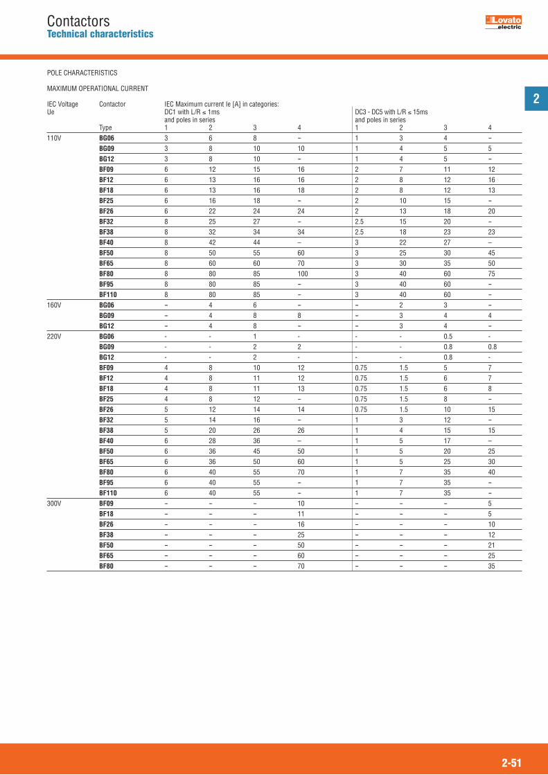
2
2-51
ContactorsTechnical characteristics
POLE CHARACTERISTICS
MAXIMUM OPERATIONAL CURRENT IEC Voltage Contactor IEC Maximum current Ie [A] in categories: Ue DC1 with L/R � 1ms DC3 - DC5 with L/R � 15ms and poles in series and poles in series Type 1 2 3 4 1 2 3 4110V BG06 3 6 8 -- 1 3 4 -- BG09 3 8 10 10 1 4 5 5 BG12 3 8 10 -- 1 4 5 -- BF09 6 12 15 16 2 7 11 12 BF12 6 13 16 16 2 8 12 16 BF18 6 13 16 18 2 8 12 13 BF25 6 16 18 -- 2 10 15 -- BF26 6 22 24 24 2 13 18 20 BF32 8 25 27 -- 2.5 15 20 -- BF38 8 32 34 34 2.5 18 23 23 BF40 8 42 44 – 3 22 27 – BF50 8 50 55 60 3 25 30 45 BF65 8 60 60 70 3 30 35 50 BF80 8 80 85 100 3 40 60 75 BF95 8 80 85 -- 3 40 60 -- BF110 8 80 85 -- 3 40 60 --160V BG06 -- 4 6 -- -- 2 3 -- BG09 -- 4 8 8 -- 3 4 4 BG12 -- 4 8 -- -- 3 4 --220V BG06 - - 1 - - - 0.5 - BG09 - - 2 2 - - 0.8 0.8 BG12 - - 2 - - - 0.8 - BF09 4 8 10 12 0.75 1.5 5 7 BF12 4 8 11 12 0.75 1.5 6 7 BF18 4 8 11 13 0.75 1.5 6 8 BF25 4 8 12 -- 0.75 1.5 8 -- BF26 5 12 14 14 0.75 1.5 10 15 BF32 5 14 16 -- 1 3 12 -- BF38 5 20 26 26 1 4 15 15 BF40 6 28 36 – 1 5 17 – BF50 6 36 45 50 1 5 20 25 BF65 6 36 50 60 1 5 25 30 BF80 6 40 55 70 1 7 35 40 BF95 6 40 55 -- 1 7 35 -- BF110 6 40 55 -- 1 7 35 --300V BF09 -- -- -- 10 -- -- -- 5 BF18 -- -- -- 11 -- -- -- 5 BF26 -- -- -- 16 -- -- -- 10 BF38 -- -- -- 25 -- -- -- 12 BF50 -- -- -- 50 -- -- -- 21 BF65 -- -- -- 60 -- -- -- 25 BF80 -- -- -- 70 -- -- -- 35

2
2-52
ContactorsTechnical characteristics
IEC DC UTILISATION CATEGORYPOLE CHARACTERISTICS
MAXIMUM OPERATIONAL CURRENT
IEC Voltage Contactor IEC Maximum current Ie [A] in categories: Ue DC1 with L/R � 1ms DC3 - DC5 with L/R � 15ms and poles in series and poles in series Type 1 2 3 4 1 2 3 475V B115 160 160 160 160 140 140 140 140 B145 220 220 220 220 160 160 160 160 B180 260 260 260 260 180 180 180 180 B250 350 350 350 350 280 280 280 280 B310 375 375 375 375 310 310 310 310 B400 400 400 400 400 350 350 350 350 B500 650 650 650 650 550 550 550 550 B630 800 800 800 800 800 800 800 800110V B115 100 130 130 130 70 100 120 120 B145 110 150 150 150 80 120 140 140 B180 120 170 170 170 90 140 160 160 B250 160 300 300 300 150 250 280 280 B310 195 350 350 350 170 290 310 310 B400 250 400 400 400 200 350 350 350 B500 320 550 600 600 320 550 550 550 B630 460 800 800 800 460 800 800 800220V B115 -- 100 130 130 -- 80 100 120 B145 -- 130 150 150 -- 90 120 140 B180 -- 150 170 170 -- 100 140 160 B250 -- 250 300 300 -- 200 250 280 B310 -- 300 350 350 -- 230 290 310 B400 -- 350 400 400 -- 280 350 350 B500 -- 450 600 600 -- 450 550 550 B630 -- 700 800 800 -- 700 800 800330V B115 -- -- 100 130 -- -- 80 120 B145 - - 130 150 -- -- 90 140 B180 -- -- 150 170 -- -- 100 160 B250 -- -- 250 300 -- -- 200 280 B310 -- -- 300 350 -- -- 230 310 B400 -- -- 350 400 -- -- 280 350 B500 -- -- 450 600 -- -- 450 550 B630 -- -- 700 750 -- -- 650 700460V B115 -- -- -- 100 -- -- -- 80 B145 -- -- -- 130 -- -- -- 90 B180 -- -- -- 150 -- -- -- 100 B250 -- -- -- 250 -- -- -- 200 B310 -- -- -- 300 -- -- -- 230 B400 -- -- -- 350 -- -- -- 280 B500 -- -- -- 450 -- -- -- 450 B630 -- -- -- 700 -- -- -- 700
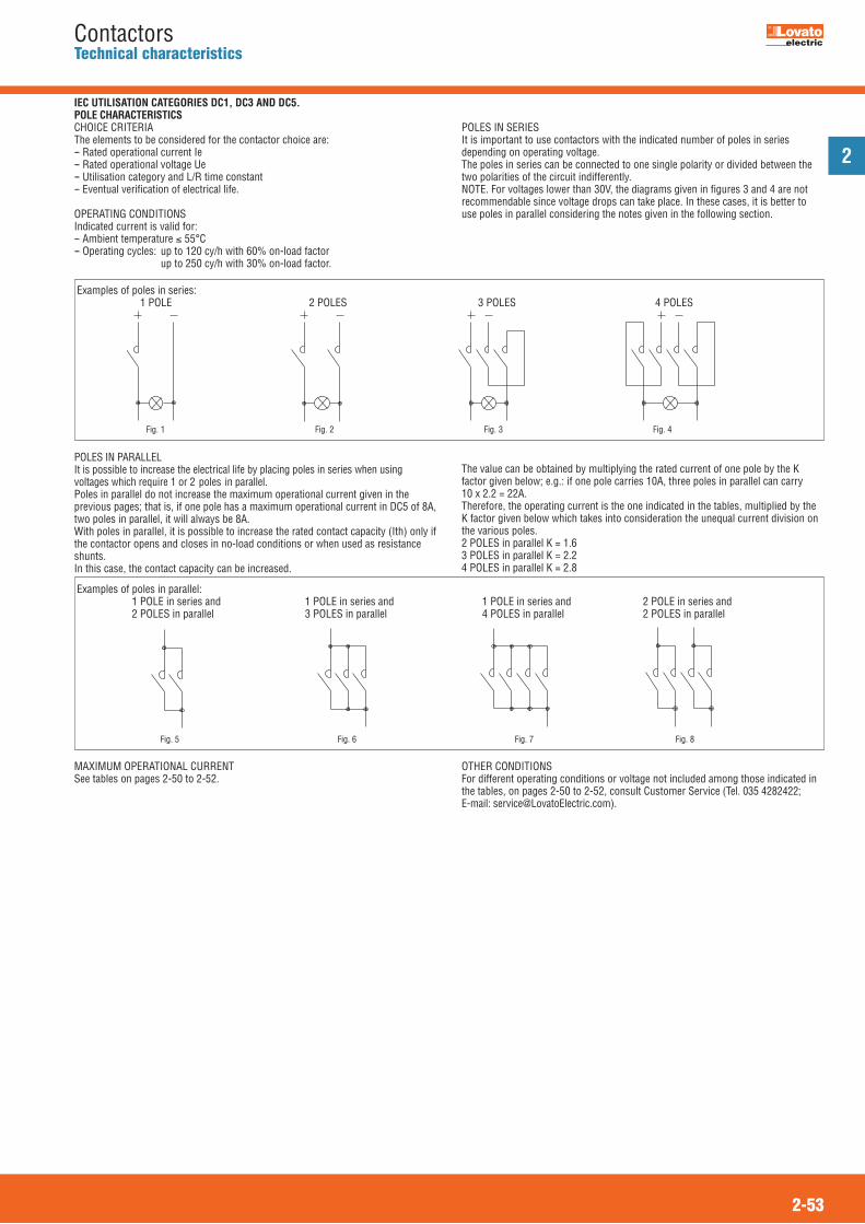
2
2-53
ContactorsTechnical characteristics
IEC UTILISATION CATEGORIES DC1, DC3 AND DC5.POLE CHARACTERISTICSCHOICE CRITERIAThe elements to be considered for the contactor choice are:-- Rated operational current Ie-- Rated operational voltage Ue-- Utilisation category and L/R time constant -- Eventual verification of electrical life.
OPERATING CONDITIONSIndicated current is valid for:-- Ambient temperature � 55°C-- Operating cycles: up to 120 cy/h with 60% on-load factor up to 250 cy/h with 30% on-load factor.
POLES IN SERIESIt is important to use contactors with the indicated number of poles in seriesdepending on operating voltage.The poles in series can be connected to one single polarity or divided between thetwo polarities of the circuit indifferently.NOTE. For voltages lower than 30V, the diagrams given in figures 3 and 4 are notrecommendable since voltage drops can take place. In these cases, it is better touse poles in parallel considering the notes given in the following section.
POLES IN PARALLELIt is possible to increase the electrical life by placing poles in series when usingvoltages which require 1 or 2 poles in parallel.Poles in parallel do not increase the maximum operational current given in theprevious pages; that is, if one pole has a maximum operational current in DC5 of 8A,two poles in parallel, it will always be 8A.With poles in parallel, it is possible to increase the rated contact capacity (Ith) only ifthe contactor opens and closes in no-load conditions or when used as resistanceshunts.In this case, the contact capacity can be increased.
The value can be obtained by multiplying the rated current of one pole by the Kfactor given below; e.g.: if one pole carries 10A, three poles in parallel can carry 10 x 2.2 = 22A.Therefore, the operating current is the one indicated in the tables, multiplied by theK factor given below which takes into consideration the unequal current division onthe various poles.2 POLES in parallel K = 1.6 3 POLES in parallel K = 2.2 4 POLES in parallel K = 2.8
MAXIMUM OPERATIONAL CURRENTSee tables on pages 2-50 to 2-52.
OTHER CONDITIONSFor different operating conditions or voltage not included among those indicated inthe tables, on pages 2-50 to 2-52, consult Customer Service (Tel. 035 4282422;E-mail: [email protected]).
Fig. 1 Fig. 2 Fig. 3 Fig. 4
Fig. 5 Fig. 6 Fig. 7 Fig. 8
Examples of poles in series: 1 POLE 2 POLES 3 POLES 4 POLES
Examples of poles in parallel: 1 POLE in series and 1 POLE in series and 1 POLE in series and 2 POLE in series and 2 POLES in parallel 3 POLES in parallel 4 POLES in parallel 2 POLES in parallel
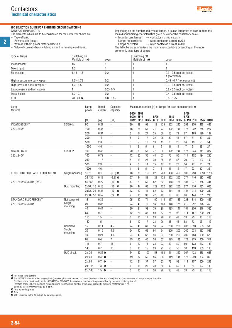
2
2-54
ContactorsTechnical characteristics
Type of lamps Switching on Switching off Multiple of In� cos� �����������������������������Multiple of In� cos�Incandescent 15 1 1 1Mixed light 1.3 1 1 1Fluorescent 1.15 - 1.3 0.2 1 0.3 - 0.5 (not corrected) 1 (corrected)High-pressure mercury vapour 1.5 - 1.75 0.2 1 0.45 - 0.7 (not corrected)High-pressure sodium vapour 1.3 - 1.5 0.2 1 0.3 - 0.5 (not corrected)Low-pressure sodium vapour 1 0.2 - 0.5 1 0.2 - 0.5 (not corrected)Metal halide 1.7 - 2.1 0.2 1 0.4 - 0.5 (not corrected)LED 20...40 � 0.6...0.95 1 0.6...0.95
Lamp Lamp Rated Capacitorfeatures power current capacity
[W] [A] [μF]INCANDESCENT 50/60Hz 60 0.27 -220...240V 100 0.45 - 200 0.91 - 300 1.4 - 500 2.3 - 1000 4.6 -MIXED LIGHT 50/60Hz 100 0.45 -220...240V 160 0.72 - 250 1.13 - 500 2.3 - 1000 4.6 -ELECTRONIC BALLAST FLUORESCENT Single mounting 16 / 18 0.1 (6.8) � 32 / 36 0.18 (6.8) �
220...240V 50/60Hz (EVG) 50 / 58 0.27 (10) � Dual mounting 2x16 / 18 0.18 (10) � 2x32 / 36 0.35 (10) � 2x50 / 58 0.52 (22) �STANDARD FLUORESCENT Not corrected 15 0.35 -220...240V 50/60Hz Single 20 0.37 -
mounting 40 0.44 -
65 0.7 - 115 1.5 - 140 1.5 - Corrected 15 0.11 4.5 Single 20 0.16 4.5
mounting 40 0.24 4.5
65 0.4 7 115 0.7 18 140 0.7 18 DUO circuit 2 x 20 0.26 � - 2 x 40 0.46 � - 2 x 65 0.7 � - 2 x 115 1.3 � - 2 x 140 1.5 � -
Maximum number [n] of lamps for each contactor pole � BG06 BF09 BF80 BG09 BF12 BF26 BF40 BF95 BG12 BF18 BF25 BF32 BF38 BF50 BF65 BF110 B115 B145 B180 30 48 92 118 129 203 240 296 370 425 462 18 28 55 71 77 122 144 177 222 255 277 8 14 27 35 38 60 71 87 109 126 137 5 9 17 22 25 39 46 57 71 82 89 3 5 10 13 15 23 28 34 43 50 54 1 2 5 6 7 11 14 17 21 25 27 20 33 57 77 88 122 144 177 244 311 377 12 20 36 48 55 76 90 111 152 194 236 8 13 23 30 35 48 57 70 97 123 150 4 6 11 15 17 23 28 34 47 60 73 1 3 5 7 8 11 14 17 23 30 36 48 80 160 220 220 400 450 500 750 1050 1200 27 44 88 122 122 222 250 277 416 583 666 17 29 59 82 82 148 166 185 277 388 444 26 44 88 122 122 222 250 277 416 583 666 13 22 45 62 62 114 128 142 214 300 342 9 15 30 42 42 76 86 96 144 201 230 25 42 74 100 114 157 185 228 314 400 485 24 40 70 94 108 148 175 216 297 378 459 20 34 59 79 90 125 147 181 250 318 386 12 21 37 50 57 78 92 114 157 200 242 6 10 17 23 26 36 43 53 73 93 113 6 10 17 23 26 36 43 53 73 93 113 24 40 62 94 94 200 200 200 533 533 533 24 40 62 94 94 200 200 200 533 533 533 24 40 62 94 94 200 200 200 458 500 520 15 25 40 50 57 125 128 128 275 300 312 6 10 15 23 23 50 50 50 133 133 133 6 10 15 23 23 50 50 50 133 133 133 54 57 100 153 153 211 250 307 423 538 653 19 32 56 86 86 119 141 173 239 304 369 12 21 37 57 57 78 92 114 157 200 242 6 11 20 30 30 42 50 61 84 107 130 6 10 17 26 26 36 43 53 73 93 113
� In = Rated lamp current.� For 220/240V circuits, either single-phase (between phase and neutral) or 2-wire (between phase and phase), the maximum number of lamps is as per the table. For three-phase circuits with neutral 380/415V or 220/240V, the maximum number of lamps controlled by the same contactor is n • 3. For three-phase 380/415V circuits without neutral, the maximum number of lamps controlled by the same contactor is n • �
�3.
Electrical life is 100,000 cycles up to 55°C.� Incorporated capacitor.� Total.� With reference to the AC side of the power supplies.
IEC SELECTION GUIDE FOR LIGHTING CIRCUIT SWITCHINGGENERAL INFORMATIONThe elements which are to be considered for the contactor choice are:– Type of lamp– Power factor (cos�)– With or without power factor correction– Value of current when switching on and in running conditions.
Depending on the number and type of lamps, it is also important to bear in mind themain discriminating characteristics given below for the contactor choice:– Incandescent lamps ���contactor making capacity– Lamps not corrected � rated contactor current in AC1– Lamps corrected � rated contactor current in AC3The table below summarises the major characteristics depending on the morecommonly used type of lamps:
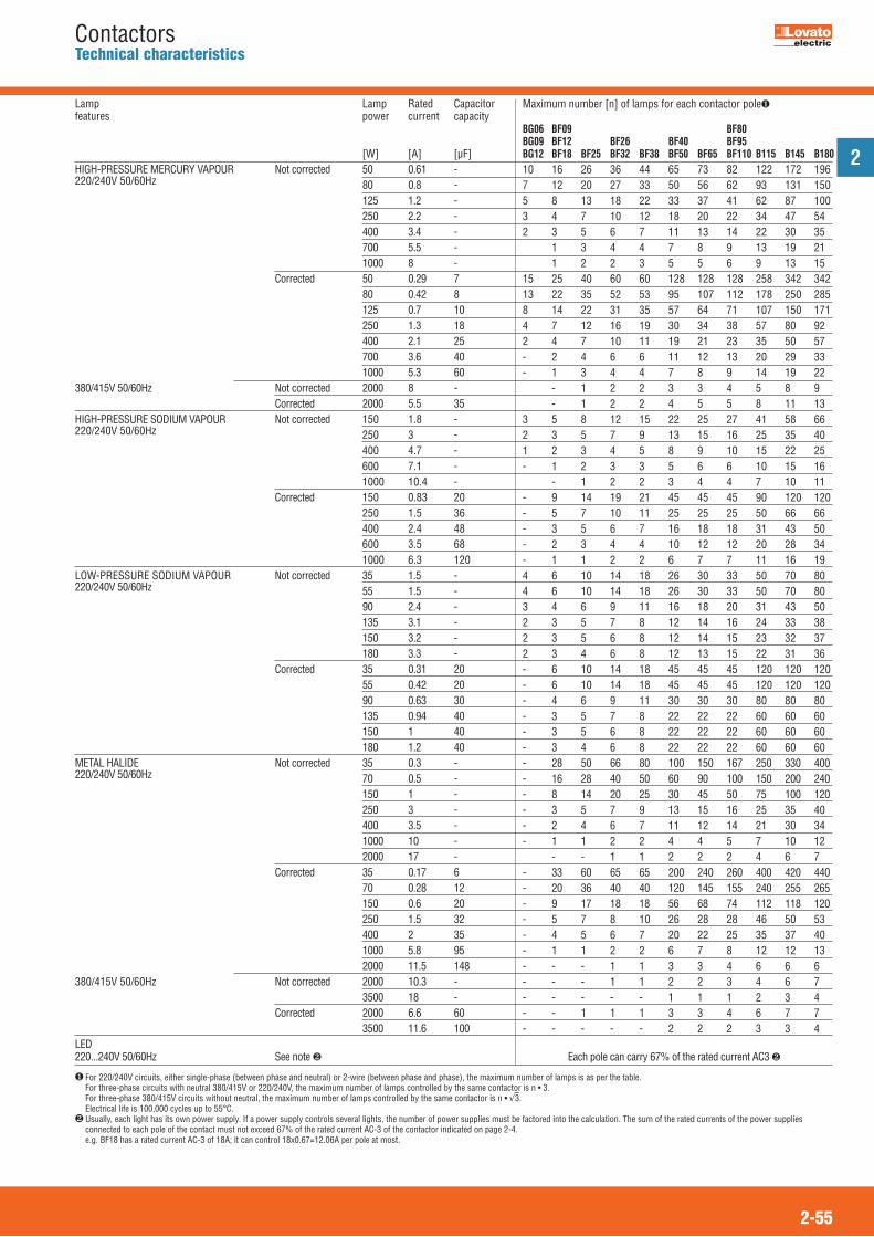
2
2-55
ContactorsTechnical characteristics
Lamp Lamp Rated Capacitorfeatures power current capacity
[W] [A] [μF]HIGH-PRESSURE MERCURY VAPOUR Not corrected 50 0.61 -220/240V 50/60Hz 80 0.8 - 125 1.2 - 250 2.2 - 400 3.4 - 700 5.5 - 1000 8 - Corrected 50 0.29 7 80 0.42 8 125 0.7 10 250 1.3 18 400 2.1 25 700 3.6 40 1000 5.3 60380/415V 50/60Hz Not corrected 2000 8 - Corrected 2000 5.5 35HIGH-PRESSURE SODIUM VAPOUR Not corrected 150 1.8 -220/240V 50/60Hz 250 3 - 400 4.7 - 600 7.1 - 1000 10.4 - Corrected 150 0.83 20 250 1.5 36 400 2.4 48 600 3.5 68 1000 6.3 120LOW-PRESSURE SODIUM VAPOUR Not corrected 35 1.5 -220/240V 50/60Hz 55 1.5 - 90 2.4 - 135 3.1 - 150 3.2 - 180 3.3 - Corrected 35 0.31 20 55 0.42 20 90 0.63 30 135 0.94 40 150 1 40 180 1.2 40METAL HALIDE Not corrected 35 0.3 -220/240V 50/60Hz 70 0.5 - 150 1 - 250 3 - 400 3.5 - 1000 10 - 2000 17 - Corrected 35 0.17 6 70 0.28 12 150 0.6 20 250 1.5 32 400 2 35 1000 5.8 95 2000 11.5 148380/415V 50/60Hz Not corrected 2000 10.3 - 3500 18 - Corrected 2000 6.6 60 3500 11.6 100LED220...240V 50/60Hz See note �
Maximum number [n] of lamps for each contactor pole� BG06 BF09 BF80 BG09 BF12 BF26 BF40 BF95 BG12 BF18 BF25 BF32 BF38 BF50 BF65 BF110 B115 B145 B180 10 16 26 36 44 65 73 82 122 172 196 7 12 20 27 33 50 56 62 93 131 150 5 8 13 18 22 33 37 41 62 87 100 3 4 7 10 12 18 20 22 34 47 54 2 3 5 6 7 11 13 14 22 30 35 1 3 4 4 7 8 9 13 19 21 1 2 2 3 5 5 6 9 13 15 15 25 40 60 60 128 128 128 258 342 342 13 22 35 52 53 95 107 112 178 250 285 8 14 22 31 35 57 64 71 107 150 171 4 7 12 16 19 30 34 38 57 80 92 2 4 7 10 11 19 21 23 35 50 57 - 2 4 6 6 11 12 13 20 29 33 - 1 3 4 4 7 8 9 14 19 22 - 1 2 2 3 3 4 5 8 9 - 1 2 2 4 5 5 8 11 13 3 5 8 12 15 22 25 27 41 58 66 2 3 5 7 9 13 15 16 25 35 40 1 2 3 4 5 8 9 10 15 22 25 - 1 2 3 3 5 6 6 10 15 16 - 1 2 2 3 4 4 7 10 11 - 9 14 19 21 45 45 45 90 120 120 - 5 7 10 11 25 25 25 50 66 66 - 3 5 6 7 16 18 18 31 43 50 - 2 3 4 4 10 12 12 20 28 34 - 1 1 2 2 6 7 7 11 16 19 4 6 10 14 18 26 30 33 50 70 80 4 6 10 14 18 26 30 33 50 70 80 3 4 6 9 11 16 18 20 31 43 50 2 3 5 7 8 12 14 16 24 33 38 2 3 5 6 8 12 14 15 23 32 37 2 3 4 6 8 12 13 15 22 31 36 - 6 10 14 18 45 45 45 120 120 120 - 6 10 14 18 45 45 45 120 120 120 - 4 6 9 11 30 30 30 80 80 80 - 3 5 7 8 22 22 22 60 60 60 - 3 5 6 8 22 22 22 60 60 60 - 3 4 6 8 22 22 22 60 60 60 - 28 50 66 80 100 150 167 250 330 400 - 16 28 40 50 60 90 100 150 200 240 - 8 14 20 25 30 45 50 75 100 120 - 3 5 7 9 13 15 16 25 35 40 - 2 4 6 7 11 12 14 21 30 34 - 1 1 2 2 4 4 5 7 10 12 - - 1 1 2 2 2 4 6 7 - 33 60 65 65 200 240 260 400 420 440 - 20 36 40 40 120 145 155 240 255 265 - 9 17 18 18 56 68 74 112 118 120 - 5 7 8 10 26 28 28 46 50 53 - 4 5 6 7 20 22 25 35 37 40 - 1 1 2 2 6 7 8 12 12 13 - - - 1 1 3 3 4 6 6 6 - - - 1 1 2 2 3 4 6 7 - - - - - 1 1 1 2 3 4 - - 1 1 1 3 3 4 6 7 7 - - - - - 2 2 2 3 3 4
Each pole can carry 67% of the rated current AC3 �
� For 220/240V circuits, either single-phase (between phase and neutral) or 2-wire (between phase and phase), the maximum number of lamps is as per the table. For three-phase circuits with neutral 380/415V or 220/240V, the maximum number of lamps controlled by the same contactor is n • 3. For three-phase 380/415V circuits without neutral, the maximum number of lamps controlled by the same contactor is n • �
�3.
Electrical life is 100,000 cycles up to 55°C.� Usually, each light has its own power supply. If a power supply controls several lights, the number of power supplies must be factored into the calculation. The sum of the rated currents of the power supplies
connected to each pole of the contact must not exceed 67% of the rated current AC-3 of the contactor indicated on page 2-4. e.g. BF18 has a rated current AC-3 of 18A; it can control 18x0.67=12.06A per pole at most.

Capacitor power Voltage 220-230V Voltage 380-500V[kvar] [] [W] [] [W]2.5-5 3900 12 8200 1210-15 1800 25 4300 2520-50 1000 50 2200 50
2
2-56
ContactorsTechnical characteristics
Contactor IEC Maximum IEC Fuse IEC maximum operational power rated permissible maximum at voltages: current peak operational 220V �400V current voltage 230V 380V 415V 500V gG 240V 400V 440V 660/690VType [A] [A] [V] [A] [kvar] [kvar] [kvar] [kvar]BF09 A 12 500 690 16 4.5 7.5 9 10BF12 A 18 550 690 25 7 12.5 12 14BF18 A 23 1000 690 32 9 15 16 18BF25 A 23 1000 690 32 9 15 16 18BF26 A 30 1400 690 40 11 20 22 22BF32 A 36 1700 690 50 14 25 27 30BF38 A 43 1900 690 63 17 30 30 34BF40 A 50 2500 1000 100 20 35 40 45BF50 A 58 2500 1000 80 22 40 41 45BF65 A 65 2500 1000 100 26 45 50 52BF80 A 75 2500 1000 125 30 50 56 60BF95 90 3000 1000 125 34 60 65 70BF110 90 3000 1000 125 34 60 65 70B115 130 3200 1000 200 50 87 93 115B145 150 3400 1000 200 57 100 108 130B180 170 3600 1000 250 65 112 122 150B250 240 5100 1000 315 91 158 172 210B310 265 5900 1000 315 105 184 200 245B400 320 7500 1000 400 122 211 230 280B500 500 9000 1000 630 190 330 360 430B630 610 11000 1000 800 230 400 432 520
V WU
642
531
10
L2 L3L1
.1
.2
.1
.2KM1
FU1
R
POWER FACTOR CORRECTION CAPACITORSCHOICE CRITERIAThe contactor during the closing transition is influenced by electrical currentshaving high frequencies and high amplitudes.The frequencies of these currents range between 1 and 10kHz; the amplitudes musthave values lower than the maximum permissible current peak of the contactor tobe used.
The use of contactors with the above operational powers is allowable only when thepeak current, in the installation point of the power factor correction board, is lowerthan the values stated in the table.If this condition is not verified, it is necessary to use limiting inductances or specificcontactors stated on page 2-14. Consult Customer Service (see contact details oninside front cover) to obtain detailed information on the correct use of contactorswithout limiting inductances.
LIMITING INDUCTANCESThe use of limiting inductances is imperative when the system inductances (linetransformer and cables), upstream of the power factor correction panel, are notable to maintain the maximum connecting current within the limit value of thecontactor used.
FAST DISCHARGE RESISTANCES OF CAPACITORSThe use of the contactor, according to the wiring diagram given, allows the fastdischarge of the capacitors as well as the instantaneous disconnection of thecapacitors from the mains when the coil is de-energised.The resistances, indicated in the following table, guarantee the discharge within amaximum time of 2 seconds.
AMBIENT OPERATING CONDITIONSAmbient temperature: � 50 °C.For temperatures higher than 50°C up to 70 °C, stated maximum operational powerratings are to be reduced by a percentage equal to the difference between theambient temperature and 50°C. Operating cycle: � 120 cy/hElectrical life: � 100,000 cycles.

2
2-57
ContactorsTechnical characteristics
Contactor Built-in IEC rated IEC fuse Maximum IEC power at �50°C (AC6b) � auxiliary operational current gG contacts �440V 220V NO 230V 380V 415V 500V 240V 400V 440V 690VType n° [A] [A] [kvar] [kvar] [kvar] [kvar]BFK09 A 1 12 16 4.5 7.5 9 10BFK12 A 1 18 25 7 12.5 14 16BFK18 A 1 23 40 9 15 17 20BFK26 A –– 30 40 11 20 22 25BFK32 A –– 36 63 14 25 27.5 30BFK38 A –– 43 63 17 30 33 36BFK50 A –– 58 80 22 38 41 46BFK65 A –– 65 100 26 45 50 56BFK80 A –– 75 125 30 50 56 65BF80K –– 90 125 34 60 65 70BF110K� –– 110 160 45 75 80 100
SPECIAL CONTACTORS FOR POWER FACTOR CORRECTION CAPACITORSGENERAL CHARACTERISTICSThese contactors are equipped with early-make contacts. This special type ofcontact has the purpose of connecting for a very brief interval, 2-3ms, during thecontactor closing, resistors which limit the connecting current of the capacitors.These resistors are then excluded when the closing operation is complete and thecurrent capacity is conveyed to the main contacts. With this type of circuit, it ispossible to obtain minor wear of all the components of the system especially fusesand capacitors ensuring a longer life and better reliability.The contactors are particularly suitable for use in automatic power factor correctionpanels since there is no need of limiting inductances and a source of heat has beeneliminated. In this way, these modular electric switchboards can be more compact.
The BFK version, figure 1, is designed for three-phase switching. The peculiarity ofthis type is in the contacts, suitable to connect limiting resistors, which close onlyfor the time needed to limit any in-rush current peak and then reopen to avoideventual flow of residual currents through the resistors.
AMBIENT OPERATING CONDITIONSAmbient temperature: � 50 °CFor ambient temperature higher than 50°C up to 70°C, maximum operational powerratings, indicated in the table, are to be reduced by a percentage equal to the differencebetween the ambient temperature and 50°C. Operating cycles: � 120 cy/h.Electrical life: � 400,000 cycles.
NOTE: See page 2-14 for order codes.�Consult Customer Service (Tel. 035 4282422; E-mail: [email protected]) for the use of contactors to switch within delta connection.� The maximum thermal current Ith of the BF110K contactor is 125A
1
A1
3
2
A2
4
5
6
13
L1 L2 L3
14
T1 T2 T3
� Auxiliary contact 13-14 is found on BFK09 A - BFK12 A - BFK18 A types only.
�Fig. 1
CHOICE OF CONTACTORS TYPE BFK/BF..K ACCORDING TO cULus LISTINGContactor Built-in UL/CSA UL/CSA Maximum UL/CSA operational auxiliary rated current protection fuse power at voltage: contacts SC/gG NO (SPST) �440V 240V 480V 600VType n° [A] [A] [kvar] [kvar] [kvar]BFK 09 1 12 16 4.5 9 10BFK 12 1 18 25 7 14 16BFK 18 1 23 40 9 17 20BFK 26 –– 30 40 11 22 27.5BFK 32 –– 36 63 14 27.5 32BFK 38 –– 43 63 17 33 36BFK50 A –– 58 80 22 41 46BFK65 A –– 65 100 26 50 56BFK80 A –– 75 125 30 60 65BF80 K –– 90 125 34 65 70BF110 K –– 110 160 40 80 100
NOTE: See page 2-14 for order codes.� Consult Customer Service (see contact details on inside front cover) for information about the use of contactors to switch within delta/wye connection.
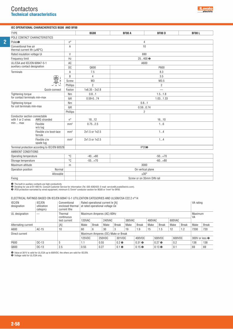
2
2-58
ContactorsTechnical characteristics
Poles� n°Conventional free air Athermal current Ith (�40°C)Rated insulation voltage Ui VFrequency limit HzUL/CSA and IEC/EN 60947-5-1 ACauxiliary contact designation DCTerminals A B Screw Phillips Quick-connect FastonTightening torque Nmfor contact terminals min-max lbftTightening torque Nmfor coil terminals min-max lbft PhillipsConductor section connectable with 1 or 2 wires AWG stranded n°min ... max Flexible mm2
w/o lug Flexible c/w boot-lace mm2
ferrule Flexible c/w mm2
spade lugTerminal protection according to IEC/EN 60529AMBIENT CONDITIONSOperating temperature °CStorage temperature °CMaximum altitude mOperation position Normal AllowableFixing
410
69025...400 �
A600 Q600 P600 7.5 8.3 4 3.5 M3 M3.5 2 2 1x6.35 - 2x2.8 –– 0.8...1 1.5...1.8 0.59-0...74 1.03...1.33
0.8...10.59...0.74
2 18...12 16...10 0.75...2.5 1...6 2x1.5 or 1x2.5 1...4
2x1.5 or 1x2.5 1...4
IP20�
-40...+60 -50...+70 -55...+70 -60...+80
3000On vertical plane
±30°Screw or on 35mm DIN rail
BG00 BF00 A BF00 D BF00 LTYPEPOLE CONTACT CHARACTERISTICS
B
A
IEC OPERATIONAL CHARACHERISTICS BG00 AND BF00
� The built-in auxiliary contacts are high-conductivity� Derating for use at 61-400 Hz. Consult Customer Service for information (Tel. 035 4282422; E-mail: [email protected]).� IP20 protection warranted by wired equipment; minimum 0.75mm2 conductor section for BG00 or 1mm2 for BF00.
ELECTRICAL RATINGS BASED ON IEC/EN 60947-5-1 UTILIZATION CATEGORIES AND UL508/CSA C22.2 n°14 IEC/EN IEC/EN Conventional Rated operational current Ie [A] VA ratingdesignation utilization enclosed thermal at rated operational voltage Ue
category current ItheUL designation –– Thermal Maximum Amperes (AC) 60Hz Maximum
continuous VAtest current 120VAC 240VAC 380VAC 480VAC 600VAC
Alternating current [A] Make Break Make Break Make Break Make Break Make Break Make BreakA600 AC-15 10 60 6 30 3 19 1.9 15 1.5 12 1.2 7200 720Direct current Maximum Amperes (DC) Make or Break
125VDC 250VDC 301VDC 400VDC 500VDC 600VDC 300V or less �P600 DC-13 5 1.1 0.55 0.2 � 0.31 � 0.27 � 0.2 138 138Q600 DC-13 2.5 0.55 0.27 0.1 � 0.15 � 0.13 � 0.1 69 69
� Value at 301V is valid for UL/CSA up to 600VDC; the others are valid for IEC/EN. � Voltage valid for UL/CSA only.
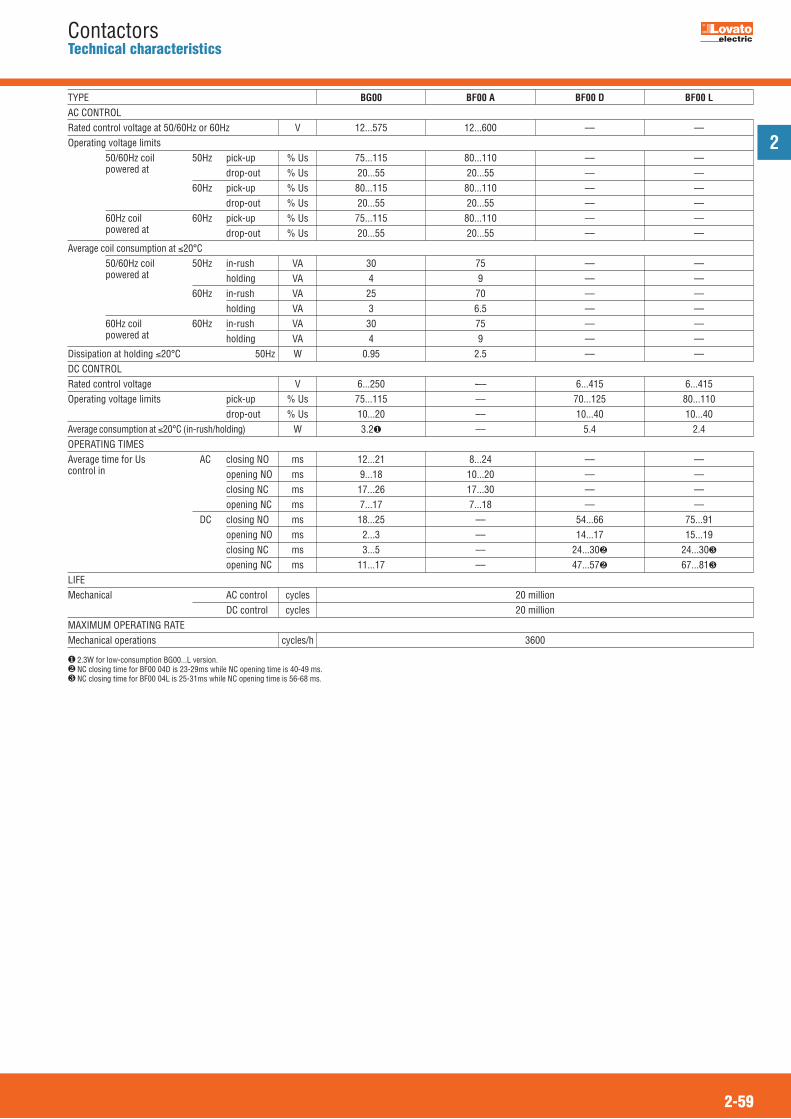
2
2-59
ContactorsTechnical characteristics
AC CONTROLRated control voltage at 50/60Hz or 60Hz VOperating voltage limits
50/60Hz coil 50Hz pick-up % Uspowered at drop-out % Us 60Hz pick-up % Us drop-out % Us60Hz coil 60Hz pick-up % Uspowered at drop-out % Us
Average coil consumption at �20°C50/60Hz coil 50Hz in-rush VApowered at holding VA 60Hz in-rush VA holding VA60Hz coil 60Hz in-rush VApowered at holding VA
Dissipation at holding �20°C 50Hz WDC CONTROLRated control voltage VOperating voltage limits pick-up % Us drop-out % UsAverage consumption at �20°C (in-rush/holding) WOPERATING TIMESAverage time for Us AC closing NO mscontrol in opening NO ms closing NC ms opening NC ms DC closing NO ms opening NO ms closing NC ms opening NC msLIFEMechanical AC control cycles
DC control cyclesMAXIMUM OPERATING RATEMechanical operations cycles/h
12...575 12...600 –– ––
75...115 80...110 –– –– 20...55 20...55 –– –– 80...115 80...110 –– –– 20...55 20...55 –– –– 75...115 80...110 –– –– 20...55 20...55 –– ––
30 75 –– –– 4 9 –– –– 25 70 –– –– 3 6.5 –– –– 30 75 –– –– 4 9 –– –– 0.95 2.5 –– ––
6...250 -–– 6...415 6...415 75...115 –– 70...125 80...110 10...20 –– 10...40 10...40 3.2� –– 5.4 2.4
12...21 8...24 –– –– 9...18 10...20 –– –– 17...26 17...30 –– –– 7...17 7...18 –– –– 18...25 –– 54...66 75...91 2...3 –– 14...17 15...19 3...5 –– 24...30� 24...30�
11...17 –– 47...57� 67...81�
20 million20 million
3600
BG00 BF00 A BF00 D BF00 LTYPE
� 2.3W for low-consumption BG00...L version.� NC closing time for BF00 04D is 23-29ms while NC opening time is 40-49 ms.� NC closing time for BF00 04L is 25-31ms while NC opening time is 56-68 ms.

2
2-60
ContactorsTechnical characteristics
Power poles n°Rated insulation voltage Ui VRated impulse withstand voltage Uimp kVOperational frequency HzOperational Conventional free air Acurrent thermal Ith (�40°C) AC3 (�440V �55°C) A AC4 (400V) � AShort-time allowable current Afor 10s (IEC/EN 60947-1) Maximum fuse size gG A aM AMaking capacity (RMS value) ABreaking capacity � 440V Aat voltage 500V A 690V AConsumption per mpole and resistance Ith W(average values)
AC3 WTerminals A [mm] B [mm] screw Phillips Quick-connect Faston SolderTightening torque Nmfor pole and coil terminals min-max lbft PhillipsConductor section connectablewith 1 or 2 wires min...max AWG stranded N° Flexible w/o mm2
lug Flexible c/w mm2
boot-lace ferrule Flexible c/w mm2
spade lugTerminal protection to IEC/EN 60529AUXILIARY CONTACT CHARACTERISTICSType of contact n°Thermal current Ith AIEC/EN 60947-5-1 designation AC DCAMBIENT CONDITIONSOperating temperature °CStorage temperature °CMaximum altitude mOperating Normalposition AllowableFixing
3 3-4 3690 690 � 690
6 6 625...400 � 25...400 � 25...400 �
16 20 20
6 9 123.3 4.0 4.896 96 96
16 20 206 10 16
92 92 12072 72 9672 72 7272 72 7210 10 102.6 4 4
0.36 0.81 1.447.5 7.5 7.54 4 4
M3 M3 M32 2 2
–– 1x6.35 - 2x2.8 –––– PIN for PCB� ––
0.8...1 0.8...1 0.8...10.59...0.74 0.59...0.74 0.59...0.74
2 2 2
18...120.75...2.5
2x1.5 or 1x2.5
2x1.5 or 1x2.5
IP20�
1-NO or NC based on configuration�
10A600Q600
-40...+60-55...+70
3000On vertical plane
± 30°Screw or on 35mm DIN rail
BG06 BG09 BG12TYPEPOLE CHARACTERISTICS
B
A
� Rated voltage Ui for BGP... types is 500V.� Derating for use at 61-400Hz. Consult Customer Service for information (Tel. 035 4282422; E-mail: [email protected]).� Current values guarantee an electrical life of about 50,000 cycles.� Dimensions and drilling distances are given on page 2-32.� IP20 protection warranted by wired equipment; minimum 0.75mm2 conductor section.� NO or NC auxiliary is highly conductive. Other characteristics are the same as the mechanical characteristics of the poles.
IEC OPERATIONAL CHARACTERISTICS BG06, BG09 AND BG12
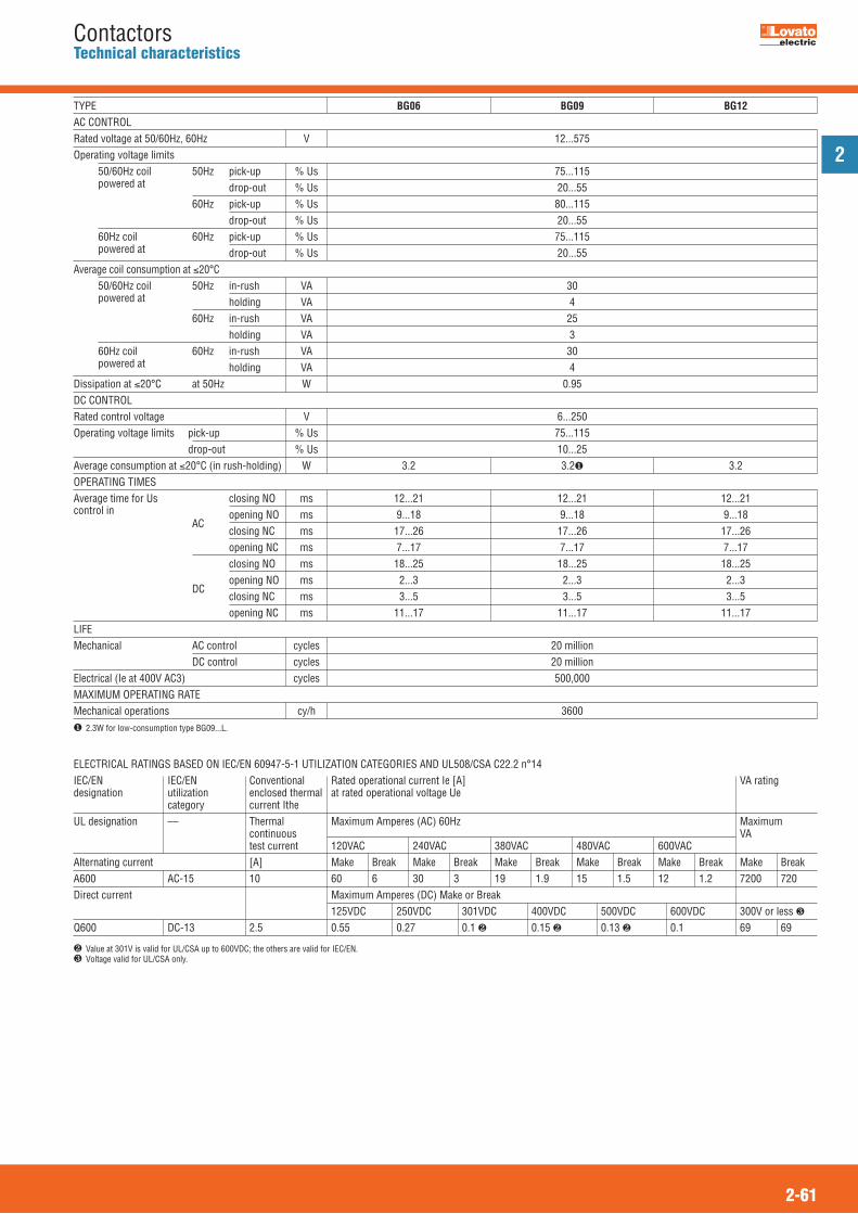
2
2-61
ContactorsTechnical characteristics
Rated voltage at 50/60Hz, 60Hz VOperating voltage limits
50/60Hz coil 50Hz pick-up % Uspowered at drop-out % Us 60Hz pick-up % Us drop-out % Us60Hz coil 60Hz pick-up % Uspowered at drop-out % Us
Average coil consumption at �20°C50/60Hz coil 50Hz in-rush VApowered at holding VA 60Hz in-rush VA holding VA60Hz coil 60Hz in-rush VApowered at holding VA
Dissipation at �20°C at 50Hz WDC CONTROLRated control voltage VOperating voltage limits pick-up % Us drop-out % UsAverage consumption at �20°C (in rush-holding) WOPERATING TIMESAverage time for Us closing NO mscontrol in
AC opening NO ms
closing NC ms opening NC ms closing NO ms
DC opening NO ms
closing NC ms opening NC msLIFEMechanical AC control cycles DC control cyclesElectrical (Ie at 400V AC3) cyclesMAXIMUM OPERATING RATEMechanical operations cy/h� 2.3W for low-consumption type BG09...L.
12...575
75...11520...55
80...11520...55
75...11520...55
304
253
304
0.95
6...25075...11510...25
3.2 3.2� 3.2
12...21 12...21 12...21 9...18 9...18 9...18 17...26 17...26 17...26 7...17 7...17 7...17 18...25 18...25 18...25 2...3 2...3 2...3 3...5 3...5 3...5 11...17 11...17 11...17
20 million20 million500,000
3600
BG06 BG09 BG12TYPEAC CONTROL
ELECTRICAL RATINGS BASED ON IEC/EN 60947-5-1 UTILIZATION CATEGORIES AND UL508/CSA C22.2 n°14 IEC/EN IEC/EN Conventional Rated operational current Ie [A] VA ratingdesignation utilization enclosed thermal at rated operational voltage Ue
category current ItheUL designation –– Thermal Maximum Amperes (AC) 60Hz Maximum
continuous VAtest current 120VAC 240VAC 380VAC 480VAC 600VAC
Alternating current [A] Make Break Make Break Make Break Make Break Make Break Make BreakA600 AC-15 10 60 6 30 3 19 1.9 15 1.5 12 1.2 7200 720Direct current Maximum Amperes (DC) Make or Break
125VDC 250VDC 301VDC 400VDC 500VDC 600VDC 300V or less �Q600 DC-13 2.5 0.55 0.27 0.1 � 0.15 � 0.13 � 0.1 69 69
� Value at 301V is valid for UL/CSA up to 600VDC; the others are valid for IEC/EN.� Voltage valid for UL/CSA only.

2
2-62
ContactorsTechnical characteristics
IEC OPERATIONAL CHARACTERISTICS BF09-BF38
3-4 3-4 3-4 3 3-4 3 3-4 690
625...400�
25 28 32 32 45 56 56(60�) 9 12 18 25 26 32 38 4.9 7.9 8.5 10 11.5 13.5 15.5 110 110 130 160 200 320 320 25 32 32 50 50 63 63 10 12 20 25 32 32 40 90 120 180 250 260 320 380 72 96 144 200 208 256 304 72 96 120 184 184 240 240 71 94 94 102 168 192 192 2.5 2.5 2.5 2.5 2.0 2.0 2.0 1.6 2.0 2.6 2.6 4.0 6.0 6.0 0.2 0.4 0.8 1.6 1.4 2.0 2.9
Clamp-screw 9.5 9.5 9.5 9.5 13 13 13 4.5 4.5 4.5 4.5 5.5 5.5 5.5 M3.5 M3.5 M3.5 M3.5 M4 M4 M4 2 2 2 2 2 2 2 1.5...1.8 1,.5...1.8 1.5...1.8 1.5...1.8 2.5...3 2.5...3 2.5...3 1.1...1.5 1.1...1.5 1.1...1.5 1.1...1.5 1.8...2.2 1.8...2.2 1.8...2.2 0.8-1 0.8-1 0.8-1 0.8-1 0.8-1 0.8-1 0.8-1 0.59-0.74 0.59-0.74 0.59-0.74 0.59-0.74 0.59-0.74 0.59-0.74 0.59-0.74 2 2 2 2 2 2 2
16...10 16...10 16...10 16...10 14...6 14...6 14...6 1...6 1...6 1...6 1...6 2.5...16 2.5...16 2.5...16 1...4 1...4 1...4 1...4 1...10 1...10 1...10
1...4 1...4 1...4 1...4 1...10 1...10 1...10
IP20� IP20� IP20� IP20� IP20� IP20� IP20�
1-NO or NC based on configuration� –– 10 –– A600 –– Q600 ––
-50...+70-60...+80
3000On vertical plane
± 30°Screw or on 35mm DIN rail
Power poles n°Rated insulation voltage Ui VRated impulse withstand votage Uimp kVOperational frequency HzOperational Conventional free air Acurrent thermal Ith (�40°C) AC3 (�440V �55°C) A AC4 (400V)� AShort-time allowable current for 10s (IEC/EN 60947-1) AMax fuse size gG A aM AMaking capacity (RMS value) ABreaking capacity �440V Aat voltage 500V A 690V AConsumption and mresistance per pole Ith W(average values)
AC3 WTerminals Type A B Screw PhillipsTightening torque Nmfor pole terminal min-max IbftTightening torque Nmfor coil terminals min-max lbft PhillipsConductor section connectablewith 1 or 2 wires min...max AWG stranded n° Flexible w/o lug mm2
Flexible c/w insulated mm2
boot-lace ferrule Flexible c/w insulated mm2
spade lug Power terminal protectionaccording to IEC/EN 60529AUXILIARY CONTACT CHARACTERISTICSType of contact n°Thermal current Ith AIEC/EN 60947-5-1 ACdesignation DCAMBIENT CONDITIONSOperating temperature °CStorage temperature °CMaximum altitude mOperating Normalposition AllowableFixing
BF09 BF12 BF18 BF25 BF26 BF32 BF38TYPEPOLE CHARACTERISTICS
B
A
� Derating for use at 61-400Hz. Consult Customer Service for information; see contact details on inside front cover.� Current values guarantee an electrical life of about 200,000 cycles.� IP20 protection warranted by wired equipment; minimum 1mm2 conductor section.� IP20 protection on front.� For this other current value, use 16mm2 wire with spade cable terminal.� NO or NC auxiliary is highly conductive. Other characteristics are the same as the mechanical characteristics of the poles.
ELEVATOR EQUIPMENT - Magnetic Motor Controllers per CSA certification File 54332 - Class 2411-03, to requirements of B44.1-04/SME A17.5-2004.Contactors, three or four poles, open type, operating coil 600VAC or less, 380VDC or less.
Maximum horsepower ratings CSAType Single phase Three phase General
120V 240V 200-208V 240V 480V 600V use[HP] [HP] [HP] [HP] [HP] [HP] [A]
BF12 1/2 11/2 3 3 71/2 71/2 28BF25 11/2 3 5 71/2 15 15 32BF38 3 5 10 10 20 20 55

2
2-63
ContactorsTechnical characteristics
12...600
80...11020...55
85...11020...55
80...11020...55
759
706.5759
2.5
6...415
70125
70 80 125 125
8011010405.42.4
8...24 8...24 10...20 5...15 14...28� 9...20�
7...18� 9...17�
54...66 53...65 14...17 14...18 24...30� 23...28 47...57� 46...56 75...91 76...92 15...19 16...20 24...30� 25...31 67...81� 63...77
20 20 20 20 20 20 2020 20 20 20 20 20 202.0 2.0 1.6 1.2 1.6 1.6 1.4
3600
Rated voltage at 50/60Hz, 60Hz VOperating voltage limits
50/60Hz coil 50Hz pick-up % Uspowered at drop-out % Us 60Hz pick-up % Us drop-out % Us60Hz coil 60Hz pick-up % Uspowered at drop-out % Us
Average coil consumption at �20°C50/60Hz coil 50Hz in-rush VApowered at holding VA 60Hz in-rush VA holding VA60Hz coil 60Hz in-rush VApowered at 60Hz holding VA
Dissipation at holding �20°C 50Hz WDC CONTROL - normal and low consumptionRated control voltage VOperating limits pick-up three-pole from % Us BF...D to % Us four-pole from %Us BF...D to %Us three and four from % Us pole BF...L to % Us drop-out for all from %Us versions to %UsAverage coil consumption BF...D W�20°C (in rush-holding) BF...L WOPERATING TIMESAverage time for AC closing NO msUs control in opening NO ms closing NC ms opening NC ms DC closing NO ms BF...D opening NO ms types
closing NC ms opening NC ms DC closing NO ms BF...L opening NO ms
types closing NC ms
opening NC msLIFE Mechanical AC control cycles(million) DC control cyclesElectrical (Ie at 400VAC3) (million) cyclesMAXIMUM OPERATING RATEMechanical operations cy/h
BF09 BF12 BF18 BF25 BF26 BF32 BF38TYPEAC CONTROL
� NC closing time for BF...T0A types is 9-25ms while NC opening time is 9-15ms.� NC closing time for BF...T0A types is 11-29ms while NC opening time is 6-14ms.
ELECTRICAL RATINGS BASED ON IEC/EN 60947-5-1 UTILIZATION CATEGORIES AND UL508/CSA C22.2 n°14 IEC/EN IEC/EN Conventional Rated operational current Ie [A] VA ratingdesignation utilization enclosed thermal at rated operational voltage Ue
category current ItheUL designation –– Thermal Maximum Amperes (AC) 60Hz Maximum
continuous VAtest current 120VAC 240VAC 380VAC 480VAC 600VAC
Alternating current [A] Make Break Make Break Make Break Make Break Make Break Make BreakA600 AC-15 10 60 6 30 3 19 1.9 15 1.5 12 1.2 7200 720Direct current Maximum Amperes (DC) Make or Break
125VDC 250VDC 301VDC 400VDC 500VDC 600VDC 300V or less �Q600 DC-13 2.5 0.55 0.27 0.1 � 0.15 � 0.13 � 0.1 69 69
� Value at 301V is valid for UL/CSA up to 600VDC; the others are valid for IEC/EN. � Voltage valid for UL/CSA only.
� NC closing time for BF...T0D types is 23-29ms while NC opening time is 40-49ms.� NC closing time for BF...T0L types is 25-31ms while NC opening time is 56-68ms.

2
2-64
ContactorsTechnical characteristics
3 3-4 3-4 3-4 3 3
1000
825 ... 400�
70 90 100 115 125 125 40 50 65 80 95 110 24 28 31 38 43 43
390 390 390 480 760 880 100 100 125 160 160 160 50 50 80 80 100 125 800 800 1090 1200 1200 1200 800 800 1090 1200 1200 1200 660 660 830 1060 1050 1050 500 500 630 800 800 800 0.8 0.8 0.8 0.6 0.6 0.6 3.9 8.0 9.7 7.9 9.4 9.4 1.3 2.0 3.4 3.8 5.4 7.3 Double lug clamp terminal � Lug clamp terminal �
9.5 9.5 9.5 9.5 12.3 12.3 11 11 11 11 12 12 M6 M6 M6 M6 M6 M6 4 4 4 4 4 4
4...52.95...3.69
0.8...10.59...0.74
1
18...2 14...2/0
1.5...35 1.5...35 1.5...35 1.5...35 6...50 6...50
1.5...35 1.5...35 1.5...35 1.5...35 6...50 6...50
IP20 front
-50...+70-60...+80
3000On vertical plane
± 30°Screw or on 35mm DIN rail
Power poles N°Rated insulation voltage Ui VRated impulse withstand voltage Uimp kVOperational frequency HzOperational Conventional free air Acurrent thermal Ith (�40°C)
AC3 (�440V �55°C) A AC4 (400V)� AShort-time allowable current for 10s A(IEC/EN 60947-1) Maximum gG Afuse size aM AMaking capacity (RMS value) ABreaking capacity �440V Aat voltage 500V A 690V AConsumption and mresistance per pole Ith W(average values)
AC3 WTerminals Type
A [mm] B [mm] Screw Metric Allen
Tightening torque Nmfor pole terminal min-max IbftTightening torque Nmfor coil terminals min-max lbft PhillipsConductor section connectablewith 1 or 2 wires min...max(1 conductor for AWG N°BF80...110) Flexible w/o lug mm2
Flexible c/w lug mm2
Power terminal protectionaccording to IEC/EN 60529AMBIENT CONDITIONSOperating temperature °CStorage temperature °CMaximum altitude mOperating Normalposition AllowableFixing
BF40 BF50 BF65 BF80 BF95 BF110TYPEPOLE CHARACTERISTICS
� Derating for use at 61-400 Hz. Consult Customer Service for information; see contact details on inside front cover.� Current values guarantee an electrical life of about 200,000 cycles.� As per IEC/EN 60947-1 designation. In addition to the main terminal which has dimensions as mentioned above, there is a second terminal entry 12.3x3.8mm for flexible busbars.
B
A
B
A
IEC OPERATIONAL CHARACTERISTICS BF40...BF110...
� ELEVATOR EQUIPMENT - Magnetic Motor Controllers per CSA certification File 54332 - Class 2411-03, to requirements of B44.1-04/SME A17.5-2004.Contactors, three or four poles, open type, operating coil 600VAC or less, 380VDC or less.
Maximum horsepower ratings CSAType Single phase Three phase General
120V 240V 200-208V 240V 480V 600V use[HP] [HP] [HP] [HP] [HP] [HP] [A]
BF65 3 10 15 15 40 50 110
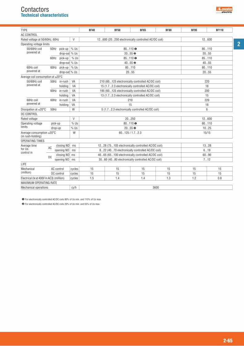
2
2-65
ContactorsTechnical characteristics
12...600 (20...250 electronically controlled AC/DC coil) 12...600
80...110 � 80...110 20...55 � 20...55 85...110 � 85...110 40...55 � 40...55 80...110 80...110 20...55 20...55
210 (60...125 electronically controlled AC/DC coil) 220 15 (1.7...2.3 electronically controlled AC/DC coil) 18 195 (60...125 electronically controlled AC/DC coil) 200 13 (1.7...2.3 electronically controlled AC/DC coil) 15 210 220 15 18 5 (1.7...2.3 electronically controlled AC/DC coil) 6
20...250 12...600 80...110 � 80...110 20...55 � 10...25 60...125 / 1.7...2.3 15/15
12...28 (75...105 electronically controlled AC/DC coil) 13...28 8...22 (40...70 electronically controlled AC/DC coil) 6...19 40...65 (65...100 electronically controlled AC/DC coil) 60...90 30...60 (40...80 electronically controlled AC/DC coil) 7...12
15 15 15 15 15 15 15 15 15 15 15 15 1.5 1.4 1.4 1.3 1.2 0.8
3600
Rated voltage at 50/60Hz, 60Hz VOperating voltage limits
50/60Hz coil 50Hz pick-up % Uspowered at drop-out % Us 60Hz pick-up % Us drop-out % Us60Hz coil 60Hz pick-up % Uspowered at drop-out % Us
Average coil consumption at �20°C50/60Hz coil 50Hz in-rush VApowered at holding VA 60Hz in-rush VA holding VA60Hz coil 60Hz in-rush VApowered at holding VA
Dissipation at �20°C 50Hz WDC CONTROLRated voltage VOperating voltage pick-up % Uslimits drop-up % UsAverage consumption �20°C W(in rush-holding) OPERATING TIMESAverage time
AC closing NO ms
for Us opening NO mscontrol in
DC
closing NO ms opening NO msLIFEMechanical AC control cycles(million) DC control cyclesElectrical (Ie at 400V in AC3) (million) cyclesMAXIMUM OPERATING RATEMechanical operations cy/h
BF40 BF50 BF65 BF80 BF95 BF110TYPEAC CONTROL
� For electronically controlled AC/DC coils 80% of Us min. and 110% of Us max.
� For electronically controlled AC/DC coils 20% of Us min. and 55% of Us max.

2
2-66
ContactorsTechnical characteristics
IEC OPERATIONAL CHARACTERISTICS B115 - B1600...
3-4 3-4 3-4 3-4 3-4 3-4 3-4 3-4 3-4 3-4 3-41000
825-400�
160 250 275 350 450 550 700 800 1000 1250 1600110 150 185 265 320 420 520 630 – – –47 57 65 92 110 133 175 210 – – –
1100 1300 1500 2200 2900 3600 4050 5040 5600 6500 8300200 250 315 400 500 630 800 1000 1000 1250 1600125 160 200 250 400 400 500 630 – – –
1100 1500 1850 2750 3150 4200 5000 6300 6300 6300 63001300 1500 1850 2500 3000 4000 5000 6300 6300 6300 63001100 1400 1600 2250 2700 3400 4500 5600 5600 5600 5600880 1200 1480 2200 2520 3360 4000 5000 5000 5000 5000600 800 1000 1500 1700 2300 2700 3400 3400 3400 34000.30 0.30 0.30 0.20 0.20 0.20 0.14 0.14 0.14 0.07 0.077.7 14.5 20.3 24.5 40.5 52.0 68.6 90 140 110 1804.0 6.8 9.7 12.5 20 32 35.0 56 – – –15 20 20 25 25 25 35 40 60 80 80
(0.6”) (0.8”) (0.8”) (1”) (1”) (1”) (1.4”) (1.6”) (2.4”) (3.1”) (3.1”)
4 4 4 5 5 5 6 6 6 10 10(0.16”) (0.16”) (0.16”) (0.2”) (0.2”) (0.2”) (0.23”) (0.23”) (0.23”) (0.39”) (0.39”)
M6 M8 M8 M10 M10 M10 M10 M12 2-M12 2-M12 2-M1210 13 13 17 17 17 17 19 19 19 19
(0.39”) (0.51”) (0.51”) (0.67”) (0.67”) (0.67”) (0.67”) (0.75”) (0.75”) (0.75”) (0.75”)1x6.35mm (0.25”) or 2x2.8mm (0.11”)
2 (Ø7mm/0.3in)10 18 18 35 35 35 35 55 55 55 557.4 13.3 13.3 25.8 25.8 25.8 25.8 40.6 40.6 40.6 40.6
10.74
20x3 25x3 25x3 30x4 30x5 30x5 50x5 60x5 60x5 100x5 100x5(0.2x0.12”) (1x0.12”) (1x0.12”) (1.2x0.16”) (1.2x0.2”) (1.2x0.2”) (2x0.2”) (2.4x0.2”) (2.4x0.2”) (4x0.2”) (4x0.2”)
70 120 150 240 -- -- -- -- – – –
-- -- -- -- 150 150 240 240 – – –
-50...+70 -20...+60-60...+80 -30...+80
3000Vertical± 30°Screw
Power poles n°Rated insulation voltage Ui VRated impulse withstand votage Uimp kVOperational frequency HzOperational Conventional free air current thermal Ith (�40°C) A AC3 (�440V �55°C) A AC4 (400V)� AShort-time allowable current for 10s (IEC/EN 60947-1) AMaximum fuse size gG A aM AMaking capacity (RMS value) ABreaking capacity �440V Aat voltage 500V A 690V A 1000V AConsumption and mresistance per pole Ith W(average values)
AC3 WTerminals A mm
B mm Screw + hex nut � mm
Quick-connect (coil) FastonCoil with G371� Phillips
Pole tightening torque Nm lbft
Coil tightening torque with G371� fitted Nm lbft
Maximum conductor section mm 1 or 2 bars N° 1 wire with lug mm2
N° 2 wire with lug mm2
AMBIENT CONDITIONSOperating temperature °CStorage temperature °CMaximum altitude mOperating Normalposition AllowableFixing
B115 B145 B180 B250 B310 B400 B500 B630 B630 B1250 B16001000TYPE
POLE CHARACTERISTICS
A
B
� Derating for use at 61-400 Hz. Consult Customer Service for information (Tel. 035 4282422; E-mail: [email protected]).� Current values guarantee an electrical life of about 200,000 cycles.� Spanner/wrench size.� G371: Adapter to transform coil faston terminals into screw type.
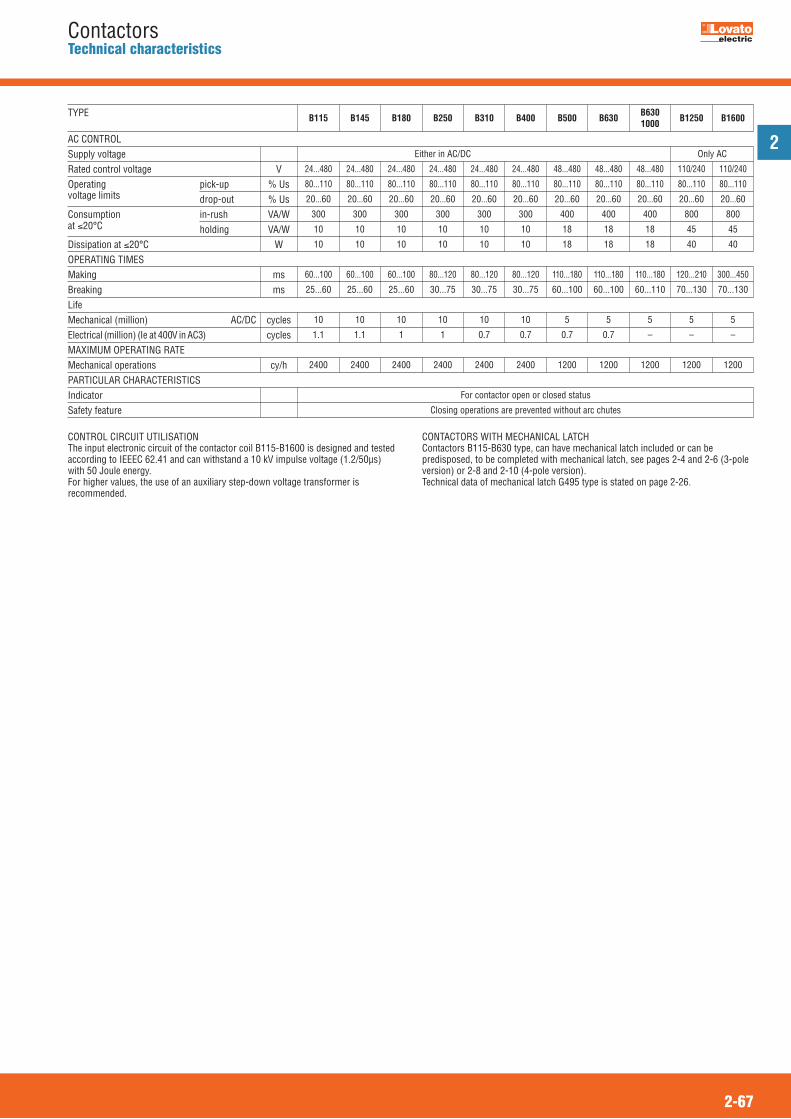
2
2-67
ContactorsTechnical characteristics
Either in AC/DC Only AC
24...480 24...480 24...480 24...480 24...480 24...480 48...480 48...480 48...480 110/240 110/240
80...110 80...110 80...110 80...110 80...110 80...110 80...110 80...110 80...110 80...110 80...110
20...60 20...60 20...60 20...60 20...60 20...60 20...60 20...60 20...60 20...60 20...60
300 300 300 300 300 300 400 400 400 800 800
10 10 10 10 10 10 18 18 18 45 45
10 10 10 10 10 10 18 18 18 40 40
60...100 60...100 60...100 80...120 80...120 80...120 110...180 110...180 110...180 120...210 300...450
25...60 25...60 25...60 30...75 30...75 30...75 60...100 60...100 60...110 70...130 70...130
10 10 10 10 10 10 5 5 5 5 5
1.1 1.1 1 1 0.7 0.7 0.7 0.7 – – –
2400 2400 2400 2400 2400 2400 1200 1200 1200 1200 1200
For contactor open or closed status
Closing operations are prevented without arc chutes
Supply voltageRated control voltage VOperating pick-up % Usvoltage limits drop-out % UsConsumption in-rush VA/Wat �20°C holding VA/WDissipation at �20°C WOPERATING TIMESMaking msBreaking msLifeMechanical (million) AC/DC cyclesElectrical (million) (Ie at 400V in AC3) cyclesMAXIMUM OPERATING RATEMechanical operations cy/hPARTICULAR CHARACTERISTICSIndicatorSafety feature
B115 B145 B180 B250 B310 B400 B500 B630 B630 B1250 B16001000TYPE
AC CONTROL
CONTROL CIRCUIT UTILISATIONThe input electronic circuit of the contactor coil B115-B1600 is designed and testedaccording to IEEEC 62.41 and can withstand a 10 kV impulse voltage (1.2/50μs)with 50 Joule energy.For higher values, the use of an auxiliary step-down voltage transformer isrecommended.
CONTACTORS WITH MECHANICAL LATCHContactors B115-B630 type, can have mechanical latch included or can bepredisposed, to be completed with mechanical latch, see pages 2-4 and 2-6 (3-poleversion) or 2-8 and 2-10 (4-pole version).Technical data of mechanical latch G495 type is stated on page 2-26.
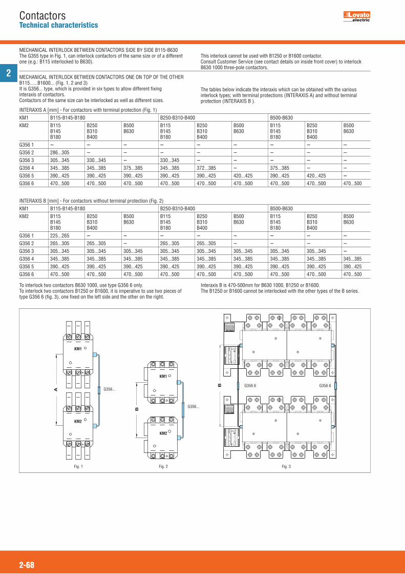
2
2-68
ContactorsTechnical characteristics
INTERAXIS A [mm] - For contactors with terminal protection (Fig. 1)KM1 B115-B145-B180 B250-B310-B400 B500-B630KM2 B115 B250 B500 B115 B250 B500 B115 B250 B500 B145 B310 B630 B145 B310 B630 B145 B310 B630 B180 B400 B180 B400 B180 B400 G356 1 --- --- --- --- --- --- --- --- ---G356 2 286...305 --- --- --- --- --- --- --- ---G356 3 305...345 330...345 --- 330...345 --- --- --- --- ---G356 4 345...385 345...385 375...385 345...385 372...385 --- 375...385 --- ---G356 5 390...425 390...425 390...425 390...425 390...425 420...425 390...425 420...425 ---G356 6 470...500 470...500 470...500 470...500 470...500 470...500 470...500 470...500 470...500
INTERAXIS B [mm] - For contactors without terminal protection (Fig. 2)KM1 B115-B145-B180 B250-B310-B400 B500-B630KM2 B115 B250 B500 B115 B250 B500 B115 B250 B500 B145 B310 B630 B145 B310 B630 B145 B310 B630 B180 B400 B180 B400 B180 B400 G356 1 225...265 --- --- --- --- --- --- --- ---G356 2 265...305 265...305 --- 265...305 265...305 --- --- --- ---G356 3 305...345 305...345 305...345 305...345 305...345 305...345 305...345 305...345 ---G356 4 345...385 345...385 345...385 345...385 345...385 345...385 345...385 345...385 345...385G356 5 390...425 390...425 390...425 390...425 390...425 390...425 390...425 390...425 390...425G356 6 470...500 470...500 470...500 470...500 470...500 470...500 470...500 470...500 470...500
B
A
G356...
G356...
KM2
KM1
KM2
KM1
MECHANICAL INTERLOCK BETWEEN CONTACTORS ONE ON TOP OF THE OTHERB115......B1600... (Fig. 1, 2 and 3)It is G356... type, which is provided in six types to allow different fixinginteraxis of contactors. Contactors of the same size can be interlocked as well as different sizes.
The tables below indicate the interaxis which can be obtained with the variousinterlock types; with terminal protections (INTERAXIS A) and without terminalprotection (INTERAXIS B ).
To interlock two contactors B630 1000, use type G356 6 only. To interlock two contactors B1250 or B1600, it is imperative to use two pieces oftype G356 6 (fig. 3), one fixed on the left side and the other on the right.
Interaxis B is 470-500mm for B630 1000, B1250 or B1600.The B1250 or B1600 cannot be interlocked with the other types of the B series.
Fig. 1 Fig. 2
B G356 6G356 6
Fig. 3
B
MECHANICAL INTERLOCK BETWEEN CONTACTORS SIDE BY SIDE B115-B630The G355 type in Fig. 1, can interlock contactors of the same size or of a differentone (e.g.: B115 interlocked to B630).
This interlock cannot be used with B1250 or B1600 contactor.Consult Customer Service (see contact details on inside front cover) to interlockB630 1000 three-pole contactors.
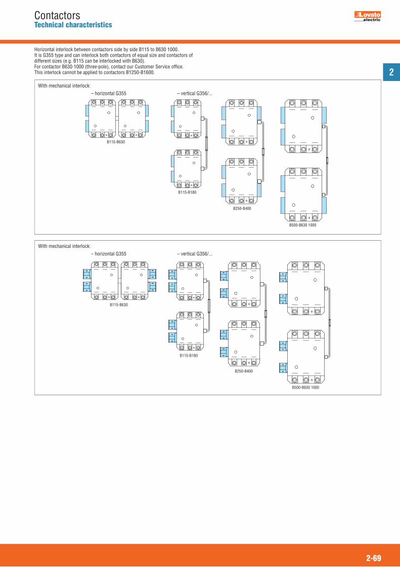
2
2-69
ContactorsTechnical characteristics
Horizontal interlock between contactors side by side B115 to B630 1000.It is G355 type and can interlock both contactors of equal size and contactors ofdifferent sizes (e.g. B115 can be interlocked with B630). For contactor B630 1000 (three-pole), contact our Customer Service office.This interlock cannot be applied to contactors B1250-B1600.
B115-B630
B115-B180
B250-B400
B500-B630 1000
With mechanical interlock:
With mechanical interlock:
B115-B630
B115-B180
B250-B400
B500-B630 1000
– horizontal G355 – vertical G356/...
– horizontal G355 – vertical G356/...