Embed Size (px)
Citation preview

Page 1 of 1 ~ . E D T 618224 ENGINEERING DATA TRANSMITTAL PEB 13 1998
2. To: (Receiving Organization) 3 . From: (Originating Organization) 4. Related EDT No.:
5. proj .IProg./Dept ./Div. :
D i s t r i b u t i o n TWRS Equip. Engrg. n /a 6 . Design Authority1 Design AgentICog. 7. Purchase Order No.:
Engr.: W-030 TWRS/TPCN NB604 JR Kriskovich n/a 8. Originator Remarks: 9. Equip./Component No.:
n/a FOR APPROVAL AND RELEASE OF A NEW SUPPORTING DOCUMENT.
11. Receiver Remarks: 11A. Design Baseline Document? [ X I Yes [ ] No
I O . SystemlBldg./Facility:
12. Major Assm. Dwg. No.: 241-AY/AZ
H-2-131000, H-2-131075, & H-2-131076
13. PermitlPermit Application No.: n l a
I 14. Rewired ResDonse Date: I
BD-7400-172-2 (05196) GEF097

> HNF-1788, Rev. 0
Project W-030 Safety Class Upgrade Summary Report
James R. Kriskovich Lockheed Martin Hanford Corporation, Rich1 and, WA 99352 U.S. Department of Energy Contract DE-AC09-96RL13200
EDT: 618224 UC: 506 Org Code: LM353000 Charge Code: NB604 B&R Code: EW3130010 Total Pages:3g
Key Words: ventilation, upgrades, primary confinement, safety class
Abstract: This document presents a summary of safety class criteria for the 241-AY/AZ Tank Farm primary ventilation system upgrade under Project W-030, and recommends acceptance of the system as constructed, based on a review of supporting documentation.
TRADEMARK DISCLAIMER. Reference herein to any specific commercial product, process, or service by trade name, trademark, manufacturer, or otherwise, does not necessarily constitute or imply its endorsement, recommendation, or favoring by the United States Government or any agency thereof or its contractors or subcontractors.
Printed in the United States of America. To obtain copies of this document, contact: WHC/BCS Document Control Services, P.O. Box 1970, Mailstop H6-08, Richland WA 99352, Phone (509) 372-2420; Fax (509) 376-4989.
2 1 3 9f
Date
Approved for Public Release A-6400-073 (10/95) GEF321

PROJECT W-030 SAFETY CLASS UPGRADE SUMMARY REPORT
HNF-1788 REV. 0
JIM KRISKOVICH LOCKHEED MARTIN HANFORD CORPORATION
FEBRUARY 13, 1998
HNF-1788 Rev . 0
TABLE OF CONTENTS
. . . . . . . . . . . . . . . . . . . . . . . . . . . 1.0 INTRODUCTION 1
2.0 CRITERIA 1 2.1 Procurement 2
. . . . . . . . . . . . . . . . . . . . . . . . . . . . . . . . . . . . . . . . . . . . . . . . . . . . . .
2.2 Natural Phenomena Hazards Mitigation . . . . . . . . . . . . . 3 2.3 Redundancy Requirements . . . . . . . . . . . . . . . . . . . . 3 2.4 Electrical Power Requirements . . . . . . . . . . . . . . . . . 3
3.2 Natural Phenomena Hazards Mitigation . . . . . . . . . . . . . 6 3.3 Redundancy Requirements . . . . . . . . . . . . . . . . . . . . 6 3.4 Electrical Power Requirements . . . . . . . . . . . . . . . . . 6
4.2 Natural Phenomena Hazards Mitigation . . . . . . . . . . . . . 8 4.3 Redundancy Requirement . . . . . . . . . . . . . . . . . . . . 9 4.4 Electrical Power Requirements . . . . . . . . . . . . . . . . . 10
. . . . . . . . . . . . . . . . . . . . . . . . . . . . . . . . . . . . . . . . . . . . . . . . . . . . . . 3.0 DISCUSSION 4 3.1 Procurement 4
. . . . . . . . . . . . . . . . . . . . . . . . . . . . . . . . . . . . . . . . . . . . . . . . . . . . . . . . 4.0 RESULTS 7
4.1 Procurement 7
. . . . . . . . . . . . . . . . . . . . . . . . . . . . 5.0 CONCLUSION 10
6.0 RECOMMENDATIONS 11
7.0 REFERENCES 12
. . . . . . . . . . . . . . . . . . . . . . . . . . . . . . . . . . . . . . . . . . . . . . . . . . . . . .
. . . . . . . . . . . . . . . . . . . . . . . . . . . . . . . APPENDIX A A-1
APPENDIX B B-1 . . . . . . . . . . . . . . . . . . . . . . . . . . . . . . .
1
HNF-1788 Rev. 0
PROJECT W-030 SAFETY CLASS UPGRADE SUMMARY REPORT
1.0 INTRODUCTION
This report evaluates equipment design and procurement of the 241-AY/AZ Tank Farms Ventilation Upgrade Project W-030. The system and some components originally were classified and procured as Safety Significant (SS) (WHC, 1993). The Tank Waste Remediation System (TWRS) Basis for Interim Operation (610) (LMHC, 1997b) for all TWRS facilities, which became effective on September 29, 1997, now classifies active ventilation systems on Aging Waste Facilities as Safety Class (SC).
The U.S. Department of Energy, Richland Operations Office, has authorized the startup and operation of the Project W-030 ventilation system as a SS system as originally designed (DOE-RL, 1997b) and identified in the preliminary safety equipment list developed for the project (WHC, 1993). This is a temporary exemption, pending further evaluation and resolution of the discrepancies between the BIO and the original project design requirements for safety-related equipment. This document provides that evaluation.
It was demonstrated that the system met the original safety classification requirements to which Project W-030 was designed and built (Kriskovich, 1997a). As a minimum, this included various certifications, test results, design calculations, and other appropriate documentation demonstrating that the equipment met all the requirements for a SS system.
design that may prevent it from meeting the safety classification requirements of SC based on the BIO (Kriskovich, 1997d). as follows:
Procurement of Safety Class Items
Safety Class Natural Phenomena Criteria
Safety C1 ass Redundancy Requirements
Safety Class Electrical Power Requirements.
An evaluation was performed t o determine what deficiencies exist in the
The deficiencies identified are
The purpose of this report is t o evaluate equipment design and procurement of Project W-030 and recommend what measures, based on technical information, may be required to modify or dedicate the system to SC, and whether the benefits substantiate the added cost.
2.0 CRITERIA
Appendix A identifies the components of Project W-030 that will be designated as SC or S S . (SSCs) are designated as SS or SC, based on the applicable facility safety
These safety structures, systems, and components
1

HNF-1788 Rev. 0
analyses and safety classification criteria defined in a Hanford Site procedure (PHMC, 1997~).
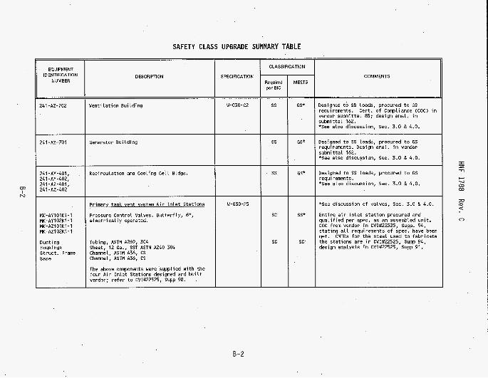
Appendix B contains a table of the components and an identification number and description listed for each component that were used to trace the specification that initiated the design and procurement of the item and any related vendor submittal or other documentation. The equipment was evaluated to determine if the design and procurement of a given item meets the requirements defined by the SC classification.
The original project design was based on the need for confinement to protect the onsite worker, corresponding to a SS classification. The 610 accidents relevant to ventilation are Flammable Gas Deflagrations and a within-structure Spray Leak (Section 5.3.2.14 and 5.3.2.20, LMHC, 1997b). According to this basis, the exhaust fans and any components supporting the safety function that provides flow are classified as SC. Included in this category are ductwork, piping, valves, supports, and electrical components whose failure could result in a loss of the safety function (flow). continuous air monitor (CAM) interlock system i s also classified as SC because of the spray leak accident scenario.
The
2.1 Procurement
All equipment for Project W-030 was classified and procured to either SS
Procurement requirements for safety SSCs are defined in a site procedure
or general service (GS) requirements.
(PHMC, 1997b). This procedure does not distinguish between SS and SC to the extent of prescribing differing procurement requirements. Therefore, SSCs originally procured as SS also meet the requirements for SC and should be suitable for use in SC applications, provided that the items in question, by their design, satisfy all the other safety functions and requirements (i.e., natural phenomena). documenting their acceptance. This report will satisfy the acceptance of those items. Procurement requirements for safety SSCs are:
Such items do not require any upgrade other than
The equipment must be supplied by a qualified supplier, or testingperification of material is required.
The vendor must provide certification documents and appropriate design calculations or test results that demonstrate compliance with the procurement requisition or specification.
For any commercial grade items (CGI), the critical characteristics must be identified and the method of dedication must be specified.
Some items originally classified and procured as GS now have a safety function because of the 610 accident analyses (see Section 3.0). procured as GS often lack the documentation required to meet the current requirements for either SS or SC equipment, unless by a special dedication process or other means of upgrade (TWRS, 1997). designate an item in this category as a safety SSC based on existing documentation, then the item would normally need to be modified, replaced, or
Items
If it is not possible to
2

HNF-1788 Rev. 0
bypassed by o t h e r equipment t h a t can perform t h e necessary s a f e t y func t ion t o maintain t h e technica l b a s i s f o r operat ing t h e system.
2.2 Natural Phenomena Hazards Mit igat ion
S t r u c t u r e s Systems and Components as i d e n t i f i e d in DOE Order 6430.1A, General Design C r i t e r i a , (DOE, 1989). DOE Order 6430.1A r e l i e s on loca l o r s i te- s p e c i f i c c r i t e r i a f o r t h e appl icable f a c t o r s used in the ana lyses . time design o f Projec t W-030 was completed, t h e loca l o r s i t e - s p e c i f i c c r i t e r i a were given i n GC-Load-01, Design Loads f o r F a c i l i t i e s , (ICF K H , 1996). Design and Evaluat ion (PHMC, 1997a) HNF-PRO-97 does not apply t o th i s p r o j e c t because of t h e conceptual design d a t e of Pro jec t W-030. HNF-PRO-97 only a p p l i e s t o design work i n i t i a t e d a f t e r October 15, 1997. r e p o r t w i l l r e l y on t h e na tura l phenomena c r i t e r i a i d e n t i f i e d i n DOE Order 6430.1A and GC-Load-01.
Natural Phenomena f o r Safety Class SSCs c o n s i s t o f severa l d i f f e r e n t events . The SC events i d e n t i f i e d i n DOE Order 6430.1A, and GC-Load-01 a r e as f o l l ows:
Designing f o r na tura l phenomena loads i s a requirement f o r Safe ty Class
A t t h e
A1 though GC-Load-01 was r e c e n t l y replaced by HNF-PRO-97, Engineer ing
As a r e s u l t , t h i s
Seismic loading = 0.29 ground motion s p e c t r a
Wind Loading = 40 m/sec (90 mph) bas ic wind speed
Tornado and Wind Miss i le = 50 x 100 mm (2x4) timber blank 7 kg (15 l b ) @ 22 m/sec (50 mph)
Volcanic Ash = 76 mm 43 inch) dry compacted ash (3 1540 kg/mA3 (96 l b l f t " )
Flooding = 40,800 mA3/sec (1,440,000 f tA3/sec)
2.3 Redundancy Requirements
Redundancy and r e l i a b i l i t y a r e a l s o SC design requirements i d e n t i f i e d i n DOE Order 6430.1A. because t h e s e a t t r i b u t e s a r e c ruc ia l t o assure the system and components a r e opera t iona l t o achieve t h e s a f e t y funct ion. Redundancy requirements apply t o both e l e c t r i c a l and mechanical systems. Redundancy i s not requi red f o r SS a p p l i c a t i o n s ; t h e r e f o r e , th is r e p o r t eva lua tes t h e n e c e s s i t y and adequacy f o r SC redundancy.
The requirements a r e important f a c t o r s i n SC design
2.4 E l e c t r i c a l Power Requirements
As was the case f o r redundancy, e l e c t r i c a l power i s a key component t o assure t h a t the s a f e t y func t ion of the system i s met. d i f f e r , a s i d e n t i f i e d i n HNF-W030-TI-001 (Kriskovich, 1997d), between SS and SC. The primary d i f f e r e n c e between t h e two e l e c t r i c a l power c r i t e r i a i s emergency power.
The requirements
For SS appl ica t ions emergency power i s not requi red ;
3

HNF-1788 Rev. 0
however, for SC applications it is required according to DOE Order 6430.1A. This report will evaluate whether it is necessary that emergency power be available to support the new ventilation system and if the adequacy of the original design is sufficient.
3.0 DISCUSSION
3.1 Procurement
Safety SSCs for Project W-030 were procured to SS requirements based on the original Project W-030 SEL (WHC, 1993). Items requiring an upgrade from SS to SC constitute a majority of those tabulated in Appendix E. Since the same procurement requirements apply for both SS and SC (PHMC, 1997b), it is possible, where necessary, to upgrade the SS items to SC based on a review of existing vendor submittal and other project documentation against the safety functions and failure modes and effects in the BIO.
Most of the existing primary ventilation valves, or dampers, were
Based on the performance of the valve and Appendix A, these valves
procured based on structural integrity of the valve body as it forms part of the confinement boundary, with no safety function attributed to the valve operator. also contribute to the safety function of flow. In addition to maintaining their structural integrity, the valves in the primary flow path must not fail, in either a closed or open position under normal operating conditions, unless they are in a location where they can be bypassed. Otherwise, their failure could lead to a loss of ventilation and accumulation of flammable gas in the tank. This failure mode is identified in Appendix A.
their use, as procured, because of the additional failure mode and its effect on safety function. inherently rugged and not prone to failure. The most common mode of failure is the inability to seat properly, as opposed to a major loss of function. This, combined with the relative ease of replacement, means that the valves are not a major concern in safety function and reliability, even when the additional criteria are considered. The original criteria of confinement, which ensured general integrity of the valve and valve body, can be relied on to provide the characteristics needed to support this safety application.
By design, most instrument loops depend on an interface through the Monitor and Control System (MCS) to perform their function. housed in the local control units (LCUs), those parts of the system which process and route various instrument signals and actually provide redundant, independent control o f the ventilation system. tested to withstand a SS seismic event as a procurement requirement. are three instrument loops that currently interface with the MCS and LCUs that are safety related. safety-re1 ated instrumentation they support are not considered because the system can operate manually without the MCS and LCUs. interface was not evaluated.
Several characteristics of these valves may be relied on for justifying
The valve operator is a simple mechanism that is
This interface is
The LCUs were procured SS and There
The effects of losing the function of the LCUs and the
Therefore, this
4

HNF-1788 Rev. 0
The safety SSCs that interface with the LCU are the CAM interlock or primary high-efficency particulate air (HEPA) filter pressure differential switches (depending on which control i s chosen) and the tank outlet air flow indicators and controllers. Either the CAM interlock or primary HEPA filter pressure differential will be classified as a Safety SSC to satisfy the technical safety requirement (TSR) (LMHC, 1997c) 1 imiting control for operation for the spray leak accident scenario. interlock was chosen.
For Project W-030, the CAM
For the CAM interlock, if the LCUs are lost, the stack monitor indication and alarm functions are designed to continue functioning independently of the LCU, but the fans must be shut down or switched manually in place of an automatic interlock function. Although this does not meet the requirements of Safety Class according to the BIO, design modifications are currently planned. The design modifications are part of the overall BIO implementation process to be completed before September, 1998. The modification will include an independently hardwired switch or other appropriate output function in parallel with the existing MCS software interface. In the meantime, since the alarm function is independent of the LCU and MCS interface the current design i s sufficient and acceptable.
For the air flow indicators and controllers, if the LCUs are lost the automatic flow control function, as well as remote flow indication are lost; however, local indication of flow is still available, satisfying the SC safety function. Also, tank pressure i s being utilized to indicate flow through the tank. As for the function of controlling flow, the valves remain in position on loss of signal and can be manually adjusted. controllers therefore meet the SC criteria without further qualification.
engineered equipment.
The air flow indicators and
The Standby (Diesel Powered) Electrical System was procured as SS For further discussion see Section 3.4.
A review of vendor submittal for the remaining safety SSCs that were procured SS shows that they also meet the requirements for SC, because there is no change in functional requirements and the items meet all requirements for SC. submittal are also referenced.
procured as GS that are now classified as SS or SC are as follows:
These are identified as SC in Appendix B, where the relevant
Other SSCs were procured G S . As shown in Appendix B, items originally
. Buildings: Ventilation, Generator, and Recirculation Cooling Cell ( S S ) .
High Efficient Mist Eliminator (HEME) Radiation Monitoring Instrument Loop (SS).
Normal Power Supply 500A, 400A, and 225A Main Breakers (SC).
Primary ductwork.and valving downstream of primary HEPA filters [downstream only; ductwork and valving upstream of filters was procured SS] (SC).
Hangers and supports for SC ductwork or equipment (SC).
5

HNF-1788 Rev. 0
Some of the above items may be upgraded by means of a dedication process; procedures HNF-PRO-447 (PHMC, 1997b) and HNF-PRO-0842 (LMHC, 1997a) define the requirements for this process. This approach will likely succeed with items for which ample documentation exists to verify the item can perform its safety function. The Venti 1 ati on, Generator, and Recirculation Buildings, HEME Radiation Monitor, and Normal Power Supply Breakers have sufficient documentation to warrant their use in SS or SC applications. calculations, certificates of compliance (COCs), and other submittal which support this conclusion are referenced in Appendix B.
testing, to be dedicated based on review of existing vendor submittal. Components in this category are the valves and piping (ductwork) downstream of the primary HEPA filters, including a crossover line and connections between the fans and filter trains, and the various SC pipe and equipment supports which were procured GS or fabricated from GS materials for Project W-030. Because these items were designated and procured as GS, they were supplied without certified material test reports (CMTRs) or COCs. Actions can be taken to utilize the material (Section 4.1).
Design
Other GS items are not sufficiently documented as to materials and
3 . 2 Natural Phenomena Hazards Mitigation
The natural phenomena criteria identified in Section 2.2 was evaluated for Project W-030 (Kriskovich, 1997d) against the SC criteria. relied on analyses that were already completed for Project W-030 for Safety Significant criteria. The evaluation consisted o f scaling the original analysis to the Safety Class criteria.
The evaluation
3 . 3 Redundancy Requirements
In parallel with the natural phenomena evaluation, a reliability study was performed on the system (Braun, 1997) to assess the actual benefits, in increased reliability, for upgrading the deficient items to make the system compliant with SC requirements. reliability of the old 702-A system and the new Project W-030 system configurations to operate over the course of a year with no external challenges. compliant Project W-030 system for seismic loading. both SS and SC designations.
The scope of the assessment compared the
The assessment also estimates the reliability of a fully The analysis was done for
3.4 Electrical Power Requirements
the system (Kriskovich, 1997~). reliability evaluation of the electrical power distribution system supplying the electric motor driven fans for the primary'ventilation system. also included an investigation of the past history for the time taken to restore power.
A reliability study was also performed on the electrical power supply of
The study
The scope of the study consisted of a
6
HNF-1788 Rev. 0
4.0 RESULTS
Resul t s of t h e equipment evaluat ion a r e tabula ted i n Appendix E . i d e n t i f i c a t i o n number and descr ip t ion a r e l i s t e d f o r each item of equipment, along with t h e s p e c i f i c a t i o n used t o procure the item, i f appl icable . equipment not l i s t e d i s considered non-safety r e l a t e d , or GS.
An
Any
4.1 Procurement
"Required per B I O " column conta ins t h e c l a s s i f i c a t i o n of each SSC based on t h e s a f e t y func t ion i d e n t i f i e d in t h e BIO, and as r e f l e c t e d i n Appendix A . "MEETS" column conta ins t h e present , minimum s a f e t y c l a s s i f i c a t i o n each item is judged t o s a t i s f y (SC, SS, o r GS), based on t h e eva lua t ion of procurement and design documentation aga ins t t h e c r i t e r i a discussed i n Sect ion 2.0 above. (Kriskovich, 1997a). Supporting d a t a a r e referenced i n the "COMMENTS" column; submit ta l from vendors and cont rac tors a r e re ta ined w i t h t h e corresponding s p e c i f i c a t i o n s in t h e Pro jec t W-030 f i l e s .
Items not l i s t e d as meeting t h e required s a f e t y c l a s s i f i c a t i o n a s i d e n t i f i e d i n sec t ion 3.1, based on a review of procurement submi t ta l , a r e l i s t e d below i n Table 4.1.1. item in a s a f e t y - r e l a t e d appl ica t ion , even though procured t o a lower c l a s s i f i c a t i o n , i s a l s o summarized. For a more d e t a i l e d d iscuss ion , see t h e previous s e c t i o n of this r e p o r t .
Two s a f e t y c l a s s i f i c a t i o n s a r e l i s t e d f o r each item i n Appendix B. The
The
In each case , t h e j u s t i f i c a t i o n f o r using t h e
7

HNF-1788 Rev. 0
Table 4.1.1
4.2 Natural Phenomena Hazards Mitigation
phenomena criteria were met, via the scaling method, except for six items. All six of those items failed to meet the SC seismic criteria. of the system that do not meet the seismic criteria are explained in detail in HNF-SD-W030-TI-001 (Kriskovich, 1997d) and as follows:
The evaluation completed (Kriskovich, 1997d) showed that all the natural
The portions
Sections of the ductwork
Ductwork and pipe supports
Filter room raised floor structure
Portions of the back-up generator building
Equipment functionality after a seismic event
8

HNF-1788 Rev. 0
Toggle b o l t anchorage f o r t h e cable t r a y s .
Although the above components do not meet the c r i t e r i a , the s c a l i n g method used i s more conserva t ive than o ther methods. For example, dynamic a n a l y s i s i s l e s s conserva t ive ; t h e r e f o r e , i f t h i s were performed t h e above components may meet the c r i t e r i a as i s . However, the c o s t , and time t o perform a dynamic a n a l y s i s i s s i g n i f i c a n t l y g r e a t e r than the s c a l i n g method.
The maximum amount o f over s t r e s s shown by t h e s c a l i n g was 22%. T h i s Therefore , t h e occurred i n t h e toggle b o l t anchorage f o r t h e cable t r a y s .
p o s s i b i l i t y e x i s t s t h a t dynamic ana lys i s may show t h a t t h e components do meet the c r i t e r i a .
The r e l i a b i l i t y s tudy t h a t was performed f o r Pro jec t W-030 (Braun, 1997) evaluated t h e increased r e l i a b i l i t y i f t h e SC seismic c r i t e r i a were met. Table 4.3.1 i n d i c a t e s t h e r e i s a minor increase in t h e r e l i a b i l i t y of the system. I t would be of l i t t l e benef i t t o e i t h e r perform a dynamic a n a l y s i s , o r r e p l a c e t h e equipment i n t h e f i e l d t o meet t h e c r i t e r i a .
Resul t s of analyses of representa t ive flammable gas d e f l a g r a t i o n scenar ios a r e provided in BIO sec t ion 5.3.2.14. For t h e p a r t i c u l a r analyses reported in t h i s sec t ion of t h e BIO, o f f s i t e REGs a r e exceeded f o r t h e Double Contained Receiver Tanks and Single Shel l Tanks. Onsi te REGs a r e amply exceeded f o r the p a r t i c u l a r ana lys i s scenar ios reported f o r the Double Shel l Tanks and t h e Aging Waste F a c i l i t y Tanks. As t h e r e i s cons iderable technica l uncer ta in ty assoc ia ted with Flammable Gas USQ, these p a r t i c u l a r r e p r e s e n t a t i v e acc ident scenar ios a r e not deemed t o be necessar i ly bounding o r r e p r e s e n t a t i v e of t r u e r i s k . A t th is s t a g e of t h e process t o c l o s e t h e USQ, the r e p r e s e n t a t i v e a n a l y s i s se rve t o emphasize t h e importance of design f e a t u r e s and operat ional c o n t r o l s which r igorous ly address the poten t ia l f o r flammable gas hazards . T h i s i s accomplished through t h e designat ion of SSCs a s Safe ty Class and c a s e by case cons idera t ion of the cos t -benef i t assoc ia ted with upgrading e x i s t i n g Safe ty S i g n i f i c a n t SSCs. a n a l y s i s cannot be quant i f ied i n terms of r isk s i n c e t h e base l ine r i s k i s not def ined by the p a r t i c u l a r analyses summarized i n t h e BIO.
The benef i t aspec t of th is
4 . 3 Redundancy Requirement
degree o f r e l i a b i l i t y a s cons t ruc ted , both in absolu te terms and in comparison with t h e an t iqua ted 702-A system i t wi l l rep lace . concl usi ons.
The r e l i a b i l i t y s tudy (Braun, 1997) concluded t h a t the system has a high
Table 4 .3 .1 summarizes t h e
9

HNF-1788 Rev. 0
Table 4.3.1.
1 . High Confidence w i t h Low ProbabiLity of Failure
As Table 4.3.1 indicates there is little to gain in increased reliability by replacing components with SC equivalents. several redundant features that include two separate filter trains, two fans, back-up power, two vacuum pumps (to support the CAM) and the ability to by- pass components. The only major piece of equipment that can not be bypassed is the ductwork from the tanks to the ventilation train. The only criteria that is not met to assure the ductwork remains functional is seismic loading. As Table 4.3.1 indicates the increase in reliability upon meeting the criteria is insignificant. Therefore, it is acceptable as is.
The system is designed with
Discussion of the reliability question must also consider any completion time identified in the authorization basis to enable repairs or replacement of failed components (Kriskovich, 1997d).
4.4 Electrical Power Requirements
W-030 ventilation system (Kriskovich, 1997c) concluded there is also a high degree of reliability in both the utility electrical power supply and the facility electrical supply distribution (Normal Power Supply) to the exhaust fans. distribution system will be significantly less than 72 hours. In fact, the study shows that the overall failure rate for loss of motive power is approximately 1.5 E-" per year with outage times ranging from 6 to 44 hours. Because of these findings, the Standby Electrical System is unlikely to be operated for extended periods of time, and any modifications or upgrades will not result in a significant increase in overall reliability of the ventilation system. This is also confirmed in Table 4.3.1.
The reliability study for the electrical power supply for the Project
The study demonstrated that postulated failures of the electrical
5 .0 CONCLUSION
The foregoing discussion evaluated equipment, originally procured and designed for the 241-AY/AZ Project W-030 ventilation upgrade for use in SS (and, sometimes, GS) applications, from the standpoint of the BIO accident analyses that reclassify the system as SC. documentation and review of design analyses demonstrates that most equipment meeting SS criteria also meets the requirements for SC.
A review of submitted
The remaining SS
10

HNF-1788 Rev. 0
items, and other items that were procured and designed GS and now have a SS or SC safety function identified, would normally require a dedication process, replacement, reconfiguration or additional analysis if they are to be used in a safety application. Section 4.0, Results are identified in Section 4.2, Natural Phenomena Hazards Mitigation.
It is concluded that the deficiencies are not sufficient to justify the cost of such an upgrade. analyses support this conclusion.
report identified several different alternatives to be completed to resolve the SC requirement issues discussed above along with costs associated with each alternative. Based on the costs and level of effort for each activity, the conclusion from that report supports these conclusions.
These items are tabulated in Table 4.1.1 in
Reliability studies of the system and design
The report completed (Kriskovich, 1997b) supports this conclusion. That
6.0 RECOMMENDATIONS
It is recommended that the system, as designed and procured, without modification, be accepted for SC application based on the technical information presented in this report and the fact that most safety SSCs were procured and designed to appropriate requirements. procured and designed based on differing safety functions or designated GS, reliability studies and design analyses demonstrate that the added benefit of component replacements, system modifications, or additional engineering analyses to upgrade to SC do not provide a significant increase in reliability for the system or a reduction in risk. the conclusions and recommendations from the alternative study (Kriskovich, 1997b) that identified the costs and level of effort to complete each a1 ternative.
Meeting the natural phenomena criteria as identified in DOE Order 6430.1A and GC-Load-01 is still required. Although existing ventilation systems in other farms and the existing 702-A System do not meet and no plans are in place to meet the requirement, it is recommended that a waiver be pursued against 6430.1A SC seismic natural phenomena criteria for Project W-030 system/components. The waiver would be valid for the equipment currently installed and for any changes/modifications in the future (i.e., like for like replacement). Although the system and applicable components would be designated as SC, those changes/modifications would be completed to the original criteria as identified in this report. The technical bases to support the deviation are contained or referenced within this report. order of magnitude cost estimate associated with this recommendation along with a schedule are identified in HNF-1518 (Kriskovich, 1997b).
If the above alternative is unacceptable, as an alternative, either a decision will need to be made on the applicability of DOE Order 6430.1A, or parts of the system will require additional analysis or physical upgrade to SC criteria, particularly the ductwork and valving downstream of the primary HEPA filters, discussed above as not satisfying applicable SC requirements under the new BIO criteria, and any pipe hangers and equipment supports identified
For those items originally
This recommendation is also based on
A rough
11

HNF-1788 Rev. 0
as SC. or more of the following steps:
The review process for each component in question should include one
Determine which criteria are applicable t o the item.
Document nonconformance of item by means of NCR process.
Contact vendor to determine if QA program is acceptable, and applicable to the item; conduct source inspection or other evaluation as appropriate.
Contact other sites (e.g., commercial) to inquire about similar equipment that has been qualified to similar requirements, to establish a history of satisfactory performance in SC applications.
Take samples for analysis to verify materials, where CMTRs do not exist (e.g., for pipe supports).
Test or otherwise qualify item to verify critical characteristics (in place or temporarily removed from the system).
Replace with equivalent items that are procured and qualified as safety SSCs, or reconfigure the system in such a way that the item is bypassed and its safety function is performed by other components.
Possibly perform additional design analysis.
7 .O REFERENCES
Braun, D.J., 1997, Reliability Study o f the 702-A and 702-AZ Ventilation Systems, HNF-SD-WM-CN-123, Rev. 0, Fluor Daniel Northwest, Richland, Washington.
DOE, 1989, Genera7 Design Criteria, DOE Order 6430.1A, U.S. Department of Energy, Washington, D.C. April 6, 1989.
DOE-RL, 1997a, Contract Number DE-AC06-96RL13200 - Approva7 of Key Documents for Addition t o the Tank Waste Remediation System (TWRS) Authorization Basis, Letter 97-MSD-211, J.D. Wagoner (DOE-RL) to H.J. Hatch (Fluor Daniel Hanford, Inc.), dated May 30, 1997, Department o f Energy, Richland Operations, Rich1 and, Washington.
DOE-RL, 1997b, Safety Eva7uation Report for 702-AZ Ventilation System (241-AZ-702) Safety Ana7ysis, enclosure to DOE RL Letter, J. D. Wagoner to H. J. Hatch, FDH, Contract Number DE-AC06-96RL13200 - Approva7 of the 702-AZ Ventilation System Safety Basis as Addendum Three to the Tank Waste Remediation System (TWRS) Basis for Interim Operation (BIO), Revision OC, Project W-030 Licensing and Implementation Strategy and Safety Evaluation Report (SER), 97-WSD-212, September 29, 1997.
12
HNF-1788 Rev. 0
DOE-RL, 1993, Standard Architectural-Civil Design Criteria, Design Loads for Facilities. DOE-RL-SDC-4.1, Rev. 11, U.S. Department of Energy, Richl and, Washington.
GC-Load-01, ICF KH, Richland, Washington.
HNF-SD-W030-RPT-001, Rev. 0, Lockheed Martin Hanford Corporation, Richland, Washington.
Cost Estimate, HNF-1518, Rev. 0, Lockheed Martin Hanford Corporation, Richl and, Washington.
System for Tank Farm Ventilation System Primary Exhaust Fans Building 241-AZ-702, HNF-SD-W030-ANAL-003, Rev. 0, Lockheed Martin Hanford Corporation, Richl and, Washington.
HNF-SD-W030-TI-001, Rev. 0, Lockheed Martin Hanford Corporation, Richl and, Washington.
Upgrade, Vol. IV, Sec. 3.11, HNF-PRO-0842, Rev. OA, Lockheed Martin Hanford Corp., Richland, Washington.
HNF-SD-WM-BIO-001, Rev 0-6, Lockheed Martin Hanford Company, Richland, Washington.
HNF-SD-WM-TSR-006, Rev. 0-1, Lockheed Martin Hanford Company, Richland, Washington.
and Evaluation, HNF-PRO-097, Rev. 0, Fluor Daniel Hanford, Inc., Ri chl and, Washington .
Safety Structures, Systems and Components and Management Spares, HNF-PRO-447, Rev. 0, (formerly Sec. EP 5.3 of WHC-CM-6-1, Standard Engineering Practices), Fluor Daniel Hanford, Inc., Richland, Washington.
PHMC, 1997c, Project Hanford Policy and Procedure System - Safety Structures Systems and Components, HNF-PRO-516, Rev. 0, (formerly Section 9.0 of WHC-CM-4-46, Safety Analysis Manual), Fluor Daniel Hanford, Inc., Richland, Washington.
WHC, 1993, Preliminary Safety Equipment List far Tank Farm Ventilation Upgrade, Project W-030, WHC-SD-W030-SEL-001, Rev. 0-A, Westinghouse Hanford Company, Ri chl and, Washington.
ICF KH, 1996, Design Loads for Facilities, A/E Standard - Civil/Structural,
Kriskovich, J.R., 1997a, Project W-030 Safety Equipment Evaluation,
Kriskovich, J.R., 1997b, Project W-030 Ventilation System Safety Class Upgrade
Kriskovich, J.R., 1997c, ReTiability Evaluation Electrical Power Distribution
Kriskovich, J.R., 1997d, Safety Class Evaluation Of Project W-030,
LMHC, 1997a, Replacement Item Evaluation, Commercial Grade Item Dedication and
LMHC, 199713, Tank Waste Remediation System Basis for Interim Operation,
LMHC, 1997c, Tank Waste Remediation System Technical Safety Requirements,
PHMC, 1997a, Project Hanford Policy and Procedure System - Engineering Design
PHMC, 1997b, Project Hanford Policy and Procedure System - Procurement of

HNF-1788 Rev. 0
APPENDIX A
SAFETY EQUIPNENT LIST
A- 1

SYSTEM IDENTIFICATION SAFEN FUNCTIONIS) FUNCTIONAL REQUIREMENTS
241-AYIAZ Tank Farm Aging Provides flow t o maintain Waste F a c i l i t y Primary, or flamnable gas conc. i n tank s h a l l maintain a 0.06 t o "KI", Vent i la t ion System vapor space, due t o
steady-state gas releases, 525% LFL, and removes waste a l l tanks. heat
DSTIAWF Vent i la t ion Systems
1.49 kPa (0.25 t o 6.0 in. WG) vacuum i n the vapor spaces o f
STRUCTURES
V e n t i l a t i o n Bui l d i n g
CLASSIFICATION JUSTIFICATION
sc HNF-SD-WM-BIO-001. Rev. 0, (610) Sec. 5.3.2.14, Flamnable Gas Def lagrat ions; C r i t e r i a 1.
Generator Bu i ld ing
SYSTEM, STRUCTURE, OR COMPONENT
DESCRIP~lON IDENTIFICATION SAFEN FUNCTIONIS)
NO.
Control Bui ld ing
EFFECT OF FAILURE ON SAFEN JUSTIFICATION FOR SAFETY FUNCTION SAFETY CLASSIFICATION CLASS' FAILURE MODE
Rec i rcu la t ion and Cooling C e l l Bldgs.
Crush o r rupture o f ductwork could impede flow, leading t o a loss of v e n t i l a t i o n and bui ldup of flamnable gases i n tank vapor space.
Physical damage t o generator or switchgear could e l im ina te power t o fans, leading t o a loss o f v e n t i l a t i o n 8. bu i ldup o f flamnable gases i n tank vapor space.
Event could damage cont ro l console, f i x tu res , o r other supporting hardware, o r could i n j u r e personnel.
Crush o r rupture of SC p o r t i o n o f ductwork could impede flow, leading t o a loss o f v e n t i l a t i o n and bui ldup o f flamnable gases i n tank vapor
BIO Sec. 5.3.2.14, ss** Flamnable Gas Def lagrat ions; C r i t e r i a 14.
BIO Sec. 5.3.2.14, ss** Flamnable Gas Def lagrat ions; C r i t e r i a 14.
Standard bu i l d i n g GS codes f o r general serv ice s t ruc tu res prov ide appropr iate l eve l of p ro tec t ion .
610 Sec. 5.3.2.14, ss** Flamnable Gas Def I agrat i ons; C r i t e r i a 14.
241-AZ-702
241-AZ-701
241-AZ-271
St ruc tura l damage o r col lapse due t o na tura l phenomena
Houses and supports primary exhaust fans, f i l t e r t ra ins , system I.%, and other equipment
Houses and supports backup power supply, and elec. system switch gear
Houses cont ro l room and operat ing personnel
S t ruc tura l damage o r col lapse due t o na tura l phenomena
241-AY-401, 241-AY-402, 241-AZ-401, 241-AZ-402
~
S t ruc tu ra l damage o r col lapse due t o natural phenomena
House and support r e c i r c u l a t i o n fans, I&C, and o ther re la ted equipment
S t ruc tura l damage o r col lapse due t o na tura l phenomena
I z -ll I c-l
-4 00 00
W
e
0
A- 2

Table A-1. Active Ventilation for 241-AY/AZ, Project W-030 Ventilation Upgrade. (11 Sheets)
Loss o f stack does not prevent f low and does not imnediately prevent system from performing sa fe ty funct ion.
SYSTEM, STRUCl
DESCRIPTION
P ip lng and equipment supports
S t ruc tura l f a i l u r e could a f f e c t worker safety, bu t standard b u i l d i n g codes f o r general serv ice s t ruc tu res provide appropr iate l eve l of protect ion.
Primary Vent Exhaust Stack
: OR COMPONENT
IDENTIFICATION NO.
296-A-42
MECHANICAL EQUIPMENT
SAFETY FUNCTIONIS)
Prevents loss of components due t o natural phenomena; safety c l a s s i f i c a t i o n t o match component supported
Exhausts f i l t e r e d primary f low t o atmosphere; minimizes exposure o f ons i te worker under abnormal condi t ions (un f i l t e re i release) by elevat ing discharge po in t and enhancing dispersal o e f f Luent.
Provide primary exhaust flow, t o prevent accumulation o f flamnable gases.
FAILURE MODE
St ruc tura l damage o r col lapse due t o na tura l phenomena, a f fec t ing i n t e g r i t y o r func t ion o f supported equipment
S t ruc tura l damage o r col lapse due t o na tura l phenomena
EFFECT OF FAILURE ON SAFEN EUNCTION
Damage t o SC ductwork or SC equipment could impede flow, leading t o a loss o f v e n t i l a t i o n and bui ldup o f flamnable gases i n tank vapor space; loss o f non-SC equip. does n o t a f f e c t system sa fe ty funct ion.
___
Mech. f a i l u r e of bearings, motor, o r drive, loss o f power, o r Struc. f a i l u r e of fan housing.
JUSTIFICATION FOR SAFETY CLASSIFICATION
Supports f o r pr imary fans, f i l t e r t ra ins , SC dampers, and SC ductwork a re "SC", as f a i l u r e could cause loss of flow; B I O Sec. 5 .3 .2 .14 , Flamnable Gas Def lagrat ions; C r i t e r i a 14; (supports are "GS" f o r HEME, condensers, rec i rc . loop ductwork, o ther
1 GS equip. and piping).
Fa i lu re o f f a n could el iminate the mot ive fo rce providing flow, r e s u l t i n g i n increased flamnable gas conc. i n tank vapor space ( f a n and f i l t e r bank are redundant and can be switched, bu t o f f l ine ls tandby fan may be out of service)
- - SAFETY CLASS'
GS o r sc
GS
I sc
B I O Sec. 5 .3 .2 .14 , Flamnable Gas Deflagrations; C r i t e r i a 1.
I z -!-I
I + -4 m m
W (D <
0
A-3

P P
Flamnable Gas Ie f lagrat ions; C r i t e r i a 14.
Primary pathway f o r a i r i n t o the tank; f a i l u r e could prevent flow; 810 Sec. 5.3.2.14, Flamnable Gas Deflagrations; C r i t e r i a 14.
Ductwork i s nonredundant but may be bypassed.
Table A-1. Active Ventilation for 241-AY/AZ, Project W-030 Ventilation Upgrade. (11 Sheets)
SC
GS
SYSTEM, STRUCT
DESCRIPTION
Vent i l a t ion Ductwork from lank, i n c l . equip. bypass l i n e s and bypass por t ions of Reci r c u l a t i on Loops ( re f . & I D S H-2-131062-H- 2- 131065, H-2-131075, & H-2.131076)
V e n t i l a t i o n Ductwork from Tank A i r I n l e t S ta t ion t o Tank
V e n t i l a t i o n Ductwork from lank, routed through HEME and primary condenser i n non-bypass mode ( ref . P&ID H-2-131075)
E. OR COMPONENT
IDENTIFICATION NO.
10"-V-AZIOl-M9, 1O0'-V-AZ104-D3, and par ts of:
IO"-V-AZlOO-M9, 10"-V-AZ102-M9
SAFETY FUNCTIONISI
Drovides a confined 3ath f o r primary f low from tanks.
Confinement o f rad io log ica l and hazardous materials; provides a f low path for fresh a i r i n t o the tank.
Provides a confined path f o r primary f low from tanks under normal condit ions, but can be bypassed f o r HEME and condenser maintenance, etc.
FAILURE MODE
Structura l damage o r f a i l u r e (crushing or ruptur ing)
S t ruc tura l damage or f a i l u r e (crushing)
St ructura l damage or f a i l u r e (crushing or ruptur ing)
EFFECT OF FAILURE ON SAFEN FUNCTION
luctwork i s nonredundant and Loss would preclude a i r f low from tank, leading t o a loss o f v e n t i l a t i o n and bu i ldup of flamnable gases i n tank vapor space
Ductwork i s nonredundant and loss could preclude fresh a i r f low i n t o tank, leading t o a loss of v e n t i l a t i o n and bui ldup of flamnable gases i n tank vapor space
Ductwork i s nonredundant but may be bypassed i n case of loss, and would not preclude a i r f low from tank; loss would a f f e c t e f f i c i e n c y but not sa fe ty func t ion of system.
I z T
w -4 W W
W C
0
A-4

Table A-1. Active Ventilation for 241-AY/AZ, Project W-030 Ventilation Upgrade. (11 Sheets)
Nonredundant, but can be bypassed; f a i l u r e a f fec ts e f f i c i e n c y bu t not sa fe ty func t ion of vent system.
SYSTEM, STRUC
DESCRIPTION
GS V e n t i l a t i o n Ductwork, Rec i rcu la t ion Cooling System Loop i n non-bypass mode ( r e f . P&IDS H-2-131062-H- 2-131065)
Fai lure of dampers would prevent flow; 010 Sec. 5.3.2.14, FLamnable Gas Deflagrations; C r i t e r i a 14.
Motor Operated Dampers, upstream and downstream of e i t h e r f i I t e r t r a i n
sc
Motor Operated Dampers, Tank A i r I n l e t s
Motor Operated Flow Control Dampers, o u t l e t from Tank
i. OR COMPONENT
IDENTIFICATION NO.
WV-AY1201 -M9, B"-V-AY1202-M9, B"-V-AY2201 -M9, S"-V-AY2202-M9, 5"-V-AZ1201 -M9. 5"-V-AZ1202-M9, 5"-V-AZ2201 -M9, B0'-V-AZ2202-M9,
MK-AZKI - lA , MK-AZKI-18, MK-AZKI-2A, MK-AZKI-28
MK-AYlOlKI-1, MK-AYlO2K1-1, MK-AZlOIK1-1, MK-AZlO2K1-1
MK-AYlOIK1-2, MK-AYlO2K1-2, MK-AZlOlKI-2, MK-AZlOZKI-2
SAFElY FUNCTIONISI
Confinement of rad io log ica l and hazardous materials; provides path f o r normal r e c i r c u l a t i o n f low path.
Part of primary flow path from tanks, or par t of confinement barr ier ; used t o route or reroute primary flow automatical ly (i.e., t o switch exhaust t ra ins) .
Provide a f low path for fresh a i r i n t o the tank.
Part of primary flow path from tanks; used t o regulate f low from each tank and balance system automatical ly; may be iso la ted and bypassed by manual damwrs.
FAILURE MODE
Struc tura l damage or f a i l u r e (crushing, plugging, or rup tur ing)
Mechanical or e l e c t r i c a l f a i l u r e o f damper actuator; S t ruc tura l f a i l u r e o f damper body; any f a i l u r e of damper i n a closed or open p o s i t i o n .
Mech. or elec. f a i l u r e o f damper actuator; s t r u c t u r a l f a i l u r e o f damper body; any f a i l u r e of damper i n a closed pos i t ion.
Mechanical or e l e c t r i c a l f a i l u r e o f damper actuator; s t r u c t u r a l f a i l u r e o f damper body; any f a i l u r e o f damper i n a closed o r open pos i t ion.
EFFECT OF FAILURE ON SAFETY FUNCTION
Ductwork i s nonredundant but may be bypassed i n case of Loss, and would not preclude a i r flow from tank; loss would af fect e f f i c i e n c y but not safety func t ion of system.
Damper f a i l u r e could preclude a i r f low from tank, leading t o a loss of v e n t i l a t i o n and bui ldup of flamnable gases i n tank vapor space.
Damper f a i l u r e would preclude fresh a i r f low i n t o tank, leading t o a loss of v e n t i l a t i o n and bui ldup o f flamnable gases i n tank vapor space.
Damper f a i l u r e does not el iminate f low or a b i l i t y t o contro l primary f low or system balance; damper may be bypassed and f low adjusted using manual bypass damper and flow ind icat ing instruments.
JUSTIFICATION FOR 1 1 SAFETY CLASSIFICATION
Primary pathway f o r a i r i n t o the tank; f a i l u r e o f dampers i n closed p o s i t i o n cou ld prevent flow; 810 Sec. 5.3.2.14, Flamnable Gas Deflagrations;
Damper f a i l u r e does not a f f e c t system sa fe ty function.
A- 5

? m
Table A-1. Active Ventilation for 241-AY/AZ, Project W-030 Ventilation Upgrade. (11 Sheets)
SYSTEM, STRUCT
DESCRIPTION
Manually Operated Dampers, bypass and i s o l a t i o n for primary flow path around flow contro l dampers
Manually Operated Dampers, Recirc. Loop (bypass and i s o l a t i o n dampers f o r primary f low
p a t h )
Manually Operated Dampers, balance of system, i nc l . condenser and HEME bypass and i s o l a t i o n dampers
Primary HEPA F i l t e r s
:. OR COMPONENT
IDENTlFlCATlON NO.
IK-AYIOlK1-2A1, IK-AYIOlK1-2A2, MK-AYIOlK1-2A3 (s im i la r , f o r
other 3 tanks; ref. P&ID
H-2- 131 075 )
MK-AYlOIK4-1, MK-AY101K4-2, MK-AY101K4-3, MK-AY101K4-4 ( s im i la r , f o r
other 3 tanks; re f . P&IDs
H-2-131062-H-2- 131065)
MK-AZKIO5-1A1, MK-AZKlOS-lA2, MK-AZK105-161, MK-AZK105-1B2,
MK-AZK1-3A, MK-AZK1-38,
MK-AZK108-lA. MK-AZK108-18, MK-AZK108-1C, MK-AZKIDP-IA, MK-AZKIOP-IB, MK-AZKlOP-IC
AZ-K1-4-1A. AZ-K1-4-18. AZ-K1-4-2A, AZ-K1-4-26
SAFETY FUNCTIONISI
,art of normal primary Flow path from tanks, ir pa r t of confinement sarr ier (w i th kctwork) when motor sperated flow contro l damper i s bypassed for naintenance.
Part of primary flow path from tanks, or part of confinement ba r r i e r (w i th ductwork) when rec i r c . loop i s bypassed.
Part of primary flow path from tanks; used t o route or reroute primary f low or bypass equipment f o r maintenance; may form pa r t of confinement ba r r i e r i f used f o r isolat ion.
Confinement of rad io log ica l and hazardous materials; housings form pa r t of primary f low path confinement ba r r i e r .
FAILURE MODE
lechanical f a i l u re o f lamper; structural fa i l u r e o f damper iody.
lechani ca l Fai lure o f damper i n an open sosi t ion; s t ruc tu ra l f a i l u r e o f damper 3ody.
Yechanical f a i l u r e o f damper i n a closed o r open pos i t ion; s t ruc tu ra l f a i l u r e o f damper body.
Breach due t o high temperature or pressure; substant ia l plugging due t o ice, moisture, o r dust bu i ldup not a c red ib le event.
EFFECT OF FAILURE ON SAFETY FUNCTION
r a i l u r e of i s o l a t i o n dampers i n open pos i t ion, o r bypass iamper i n a closed pos i t ion, :oncurrent w i th a f a i l u r e o f flow con t ro l damper, could Limit v e n t i l a t i o n flow from tank, leading t o a bu i ldup of Flamnable gases i n tank vapor mace.
)amper f a i l u r e concurrent wi th 3 rupture i n rec i r c . loop could l i m i t v e n t i l a t i o n f low From tank, leading t o a ouildup of flamnable gases i n tank vapor space.
Damper f a i l u r e could preclude a i r f low from tank, leading t o a Loss of v e n t i l a t i o n and bui Ldup of f lamnable gases i n tank vapor space.
Fa i l u re may resu l t i n exposure of ons i te worker, but does not prevent flow; CAM i n te r l ock and d i f f . press. switches prov ide appropr ia te l eve l of p ro tec t i on against ons i te exposure.
JUSTIFICATION FOR SAFETY CLASSIFICATION
Used t o bypass f low con t ro l damper; damper f a i l u r e could prevent o r l i m i t flow; 810 Sec. 5.3.2.14, Flamnable Gas Deflagrations; C r i t e r i a 14.
Used t o bypass rec i r c . Loop; f a i l u r e of i s o l a t i o n dampers i n open p o s i t i o n could prevent o r l i m i t flow; BIO Sec. 5.3.2.14, Flamnable Gas Deflagrations; C r i t e r i a 14.
Fa i l u re of dampers i n closed pos i t i on (o r of i s o l a t i o n dampers i n open pos i t i on ) could prevent f low; 810 Sec. 5.3.2.14, Flamnable Gas Deflagrations; C r i t e r i a 14.
CAM i n te r l ock t o fans (part of rad ia t i on moni tor ing system, RAH-AZK1-1, re f . H-2-131078) switches fans l t ra ins t o prov ide SSC contro l ; d i f f . press. switches prov ide add ' l compensatory measure.
- - SAFETY CLASS'
- - sc
sc
sc
- GS
-
A-6

Table A-1. Active Ventilation for 241-AY/AZ, Project W-030 Ventilation Upgrade. (11 Sheets)
SYSTEM, STRUC
DESCRIPTION
Primary HEGA (Charcoal) F i l t e r s
Primary Heaters
HEME
Primary Condenser
, OR COMPONENT
IDENTIFICATION NO.
A2-K1-10-lA, AZ-K1-10-16
AZ-K1-2-1A,. AZ-K1-2-18.
AZ-K1-9-1
AZ-K1-8-1
SAFETY FUNCTIONIS)
Confinement of rad io log ica l and hazardous materials; housings form par t of primary f law path confinement barr ier .
Protects f i l t e r s f r o m moisture damage and improves ef f ic iency, by heating airstream, aids i n confinement of rad io log ica l and hazardous materials; housings form par t of confinement b a r r i e r .
Confinement o f radio log i ca l and hazardous materials; confinement of major i t y of tank l i q u i d s t o "hotter" side of system t o reduce moisture, sa l ts , and rad io log ica l load on HEPA f i l t e r s ; s h e l l forms par t of confinement b a r r i e r .
Confinement of rad io log ica l and hazardous materials; confinement of ma jor i t y of tank l i q u i d s t o "hot ter" side of system t o reduce moisture, sa l ts , and rad io log ica l load on HEPA f i l t e r s ; s h e l l forms par t o f confinement barr ier .
FAILURE MODE
Breach due t o high temperature or pressure; substanti a l plugging due t o ice, moisture, or dust bui Ldup not a c red ib le event.
Heater f a i l u r e or loss of power r e s u l t i n g i n loss of airstream heating; or heater may overheat and damage f i l t e r s .
Mechanical f a i l u r e r e s u l t i n g i n carryover of l i q u i d s t o f i l t e r t r a i n .
Mechanical f a i l u r e r e s u l t i n g i n carryover of l i q u i d s t o f i l t e r t r a i n .
EFFECT OF FAILURE ON SAFETY FUNCTION
Fai lure may r e s u l t i n exposure o f ons i te worker, but does not prevent flow; CAM i n t e r l o c k and d i f f . press. switches provide appropriate l e v e l of p ro tec t ion against ons i te exposure.
Heater f a i l u r e may eventua l l y r e s u l t i n f i l t e r damage o r loss of f i l t e r e f f i c iency .
Increased contamination leve ls i n HEPA/HEGA f i l t e r t r a i n and reduced system e f f i c iency .
Increased contamination leve ls i n HEPA/HEGA f i l t e r t r a i n and reduced system e f f i c iency .
JUSTIFICATION FOR SAFETY CLASSIFICATION
CAM i n t e r l o c k provides SSC control; d i f f . press. switches provide add ' l compensatory measure.
F a i l u r e a f f e c t s l i f e and e f f i c i e n c y of f i l t e r s , but has no imnediate e f f e c t on f low or system s a f e t y function.
Nonredundant, but can be bypassed; f a i l u r e a f f e c t s e f f i c iency but not sa fe ty func t ion of f i l t e r s & v e n t system, and does not prevent flow.
Nonredundant, but can be bypassed; f a i l u r e a f f e c t s e f f i c i e n c y but not sa fe ty func t ion of f i l t e r s & vent system, and does not prevent f low.
- - SAFETY CLASS.
- - GS
- GS
- GS
- GS
I z 7
c U W W
P m <
0
A- 7

Table A-1. Ac t i ve V e n t i l a t i o n f o r 241-AY/AZ, P ro jec t W-030 V e n t i l a t i o n Upgrade. (11 Sheets)
FAILURE MODE EFFECT OF FAILURE ON SAFETY
FUNCTION SYSTEM, STRUCTURE. OR COMPONENT
SAFETY FUNCTION61 DESCRIPTION IDENTIFICATION
NO.
Primary Tank and Risers
TK-AY-101. TK-AY-102, TK-AZ-101, TK-AZ-102
.eatage or loss of confinement ,f tank waste.
Primary confinement of tank waste and vapors; connects t o a i r i n l e t and exhaust v e n t i l a t i o n ductwork.
Confinement of rad io log ica l and hazardous materials; housings form par t of confinement barr ier .
S t ruc tura l f a i l u r e o f tank or r i s e r s due t o natura l phenomena.
Breach o f f i l t e r due t o h igh temperature or pressure; subs tan t ia l plugging due t o ice, moisture, or dust bu i ldup not a c r e d i b l e event.
r e l a t e d note t o t h i s table, or BID Sec. 2.0.
:a i led f i l t e r w i l l not confine tank atmosphere i n the event ,f a tank pressurization, wi th mss. e f f e c t on ons i te worker; ?o e f f e c t on flow.
I n l e t f i l t e r s do no t car ry a s i g n i f i c a n t inventory; confinement func t ion i s i n s i g n i f i c a n t as i t applies on ly i n case of a tank pressur iza t ion .
Tank A i r I n l e t HEPA F i l t e r s
Tank A i r I n l e t P r e f i l t e r s
Helps protect i n t e g r i t y of a i r i n l e t HEPA f i l t e r .
Breach o f f i l t e r due t o h igh temperature or
F a i l u r e a f f e c t s l i f e of a i r i n l e t HEPA f i l t e r s ; no inmediate e f f e c t on confinement function.
Fai led p r e f i l t e r w i l l a l low i n l e t HEPA f i l t e r t o load up faster and lose ef f ic iency; no imnediate e f f e c t on system safety function.
pressure; subs tan t ia l plugging due t o ice, moisture, or dust bu i ldup not a c r e d i b l e event.
Heater f a i l u r e or loss of power r e s u l t i n g i n loss o f a i rs t ream heating function; a l ternat i v e l y, heater may overheat and damage f i l t e r .
Mech. f a i l u r e o f bearings, motor, or dr ive, loss of power, o r Strut. f a i l u r e of fan housing or supports.
P W
_______
Helps protect i n t e g r i t y of a i r i n l e t HEPA f i l t e r , by heating airstream.
Heater f a i l u r e may eventual ly r e s u l t i n f i l t e r damage or loss of f i l t e r e f f ic iency; no ef fect on flow.
Fai lure a f f e c t s l i f e of a i r i n l e t HEPA f i l t e r s ; no imnediate e f f e c t on confinement func t ion or f low.
GS Tank A i r I n l e t Heaters
AY101-K4-2-1, AY 102-K4-2- 1, A2101-K4-2-1, AZ102-K4-2-1
GS Rec i rcu la t ion Fans
Provide r e c i r c u l a t i o n flow f o r wastelvent cooling; housings form par t of confinement b a r r i e r but not par t of primary flow path.
Fai lure of fan could e l im ina te the motive force prov id ing r e c i r c u l a t i o n flow, r e s u l t i n g i n loss of cool ing and decreased system ef f ic iency, but not safety function.
Nonredundant, but can be bypassed; f a i l u r e l i m i t s waste coo l ing function, a f f e c t i n g e f f i c i e n c y but not sa fe ty func t ion o f vent system.
A-8

Provide power t o Loss of main Fa i l u re of f an power supply 610 Sec. 5.3.2.14, Normal Power (Ref. SUPPlY (Subsystem)
H-2-131353, exhaust fan drives. power source, e l iminates the motive force Flamnable Gas Sh. 1 ) loss of prov id ing flow, leading t o a Deflagrations;
switchgear o r bu i ldup of f l a m a b l e gases i n C r i t e r i a 14. transformer. tank vapor space.
sc
Table A-1. Ac t i ve V e n t i l a t i o n f o r 241-AY/AZ, P r o j e c t W-030 V e n t i l a t i o n Upgrade. (11 Sheets) - - SAFETY CLASS'
- - GS
JUSTIFICATION FOR SAFETY CLASSIFICATION
i, OR COMPONENT
IDENTIFICATION NO
SYSTEM, STRUCT
DESCRIPTION
EFFECT OF FAILURE ON SAFETY FUNCTION SAFETY FUNCTIONISI FAILURE MODE
lec i r c . Loop Wis tu re Separators
Fai lure could resu l t i n loss ,f cool ing and decreased system e f f i c i ency , but not safety function.
Nonredundant, but can be bypassed; f a i l u r e af fects e f f i c i ency bu t not safety func t i on of system.
Mechanical f a i l u r e resu l t i ng i n carryover of l i qu ids and loss of cooling, system e f f i c i ency .
Mechanical f a i l u r e resu l t i ng i n carryover of l i qu ids and loss of cooling, system e f f i c i ency .
Confinement of l i qu ids t o tank and reduced f i l t e r loading; housings form pa r t of confinement ba r r i e r but not pa r t of primary flow path.
Waste/vent cooling; confinement of l i qu ids t o tank and reduced f i l t e r loading; housings form part of confinement ba r r i e r but not pa r t of primary flow path.
Contains condensate i r the event of leakage from ductwork.
GS
- GS
Recirc. Loop Moisture Condensers
Nonredundant, but can be bypassed; f a i l u r e a f fec ts e f f i c i e n c y bu t not safety func t i on of system.
Fa i l u re could resu l t i n loss of cool ing and decreased system ef f ic iency, but not safety function.
S t ruc tu ra l damage o r f a i l u r e (crushing o r ruptur ing)
Encasement i s nonredundant and fa i l u re , i f concurrent wi th a p ip ing o r duct f a i l u re , would resu l t i n loss of confinement and l i q u i d containment.
Duct encasements (secondary containment system)
Condensate i s not a s ign i f i can t source term, and i s not included i n 610 accident scenarios.
Condensate i s no t a s ign i f i can t source term, and i s not included i n 810 accident scenarios.
"-ENC-M26" various ( re f .
P&IDs H-2-131062-H-2-
131065 & H-2- 131 075
F W
Pip ing i s nonredundant and f a i l u r e would resu l t i n loss of l i q u i d containment.
GS
- GS
Process condensate dra ins
Contains condensate from various equipmeni
St ructura l damage o r f a i l u r e (crushing, plugging, o r ruptur ing)
n~pc . -~27n various ( re f .
P&IDs H-2-131062-H-2-
131065 & H-2-131075)
(Ref. H-2-131077 & H-2-131081)
Loss of v e n t i l a t i o n f o r equipment cooling.
Fa i l u re has no imnediate e f f e c t on system safety function.
Mechanical f a i l u r e o f fan o r other components, loss of power.
Supplies cool ing t o fan motors and dr ives
241-AZ-702 Bui l d ing Ven t i l a t i on (Subsystem)
A-9

Table A-1. Ac t i ve V e n t i l a t i o n f o r 241-AY/AZ, P r o j e c t W-030 V e n t i l a t i o n Upgrade. (11 Sheets) - - SAFETY CLASS.
- - sc
EFFECT OF FAILURE ON SAFETY FUNCTION
SYSTEM. STRUCTURE, OR COMPONENT JUSTIFICATION FOR SAFETY CLASSIFICATION SAFEN FUNCTIONISI FAILURE MODE
DESCRIPTION IOENTIFICATION NO.
610 Sec. 5.3.2.14, Flamnable Gas Deflagrations; C r i t e r i a 14.
lackup Power
Subsystem) jUPPlY
(Ref. H-2-131353,
Sh. 2)
Fai lure of fan power supply el iminates the motive force providing flow, Leading t o a bui ldup of flamnable gases i n tank vapor space.
Loss of d iesel f u e l supply, col lapse of gen. bldg., mech. f a i l u r e o f generator.
Provide backup power t o exhaust fan dr ives on loss of normal power.
Provide power t o exhaust fans.
Fai lure of fan d r i v e el iminates the motive fo rce providing flow, leading t o a bui ldup of flamnable gases i n tank vapor space.
sc l a r i a b l e ;peed Drives
VSD-1; VSD-2 Loss or f a i l u r e of e l e c t r i c a l components by overheating or de ter io ra t ion .
F a i l u r e of fan el iminates the motive fo rce providing flow; B I O Sec. 5.3.2.14, Flamnable Gas Def Lagrations; C r i t e r i a 14.
Monitors and supports sa fe ty func t ion o f exhaust fan; 610 Sec. 5.3.2.14, Flamnable Gas Deflagrations; C r i t e r i a 14.
- sc rank F L O W
Ind icat ion Instrument
FE-AYIOIKI -2, FT-AYlOIK1-2, 8
FIC-AYIK1-2
I n d i c a t e V v e r i f i e s ra te of exhaust a i r flow from each primary tank.
Instrument malfunction, loss of ca l ibrat ion, or Loss o f power or signal.
I n a b i l i t y t o v e r i f y system i s performing sa fe ty func t ion and maintaining flow; could lead t o a bui ldup of flamnable gases i n tank vapor space.
I z n
c -4 m m
P
5 0
.oop (Tank Exhaust J u t l e t )
(s imi lar , f o r other 3 tanks;
re f . P&ID H-2-131075)
FE-AYlOIK1-1, FT-AYIOIKI-1, E
F I C - A Y I K I -1 (s imi lar , for
other 3 tanks; re f . P&ID
H-2.131075)
“ZS-“ or “ZT-/ZI -ID
various ( re f . P&IDs, i n c l .
bypass & rec i rc . lines; located with
dampers)
RIAS-AZK109-I
7 c 0
- GS Instrument
ma l f unct i on, loss of ca l ibrat ion, or loss o f power or signal.
I n a b i l i t y t o v e r i f y system a i r f low through normal tank i n l e t path; f a i l u r e does not a f fec t sa fe ty func t ion of system o r flow, as f low i s more r e l i a b l y monitored a t tank o u t l e t .
Can he lp optimize o r monitor performance of a i r i n l e t stat ions, but not necessary f o r function.
lank Flow Ind ica t ion Instrument LOOPS (Tank A i r I n l e t )
I n d i c a t e s l v e r i f i e s r a t e of fresh a i r f low i n t o primary tank ( v i a a i r i n l e t s t a t i o n only, may not include a l l sources of i n f low).
Indicates damper posit ions.
- GS Damper L i m i t
Switches, a l l manual and motor-operate d dampers ( r e f . P&IDs)
Instrument malfunction, loss of ca l ibrat ion, or loss o f power or signal.
Loss of s ignal v e r i f y i n g pos i t ions of dampers r o u t i n g primary f low path.
F a i l u r e would not a f f e c t sa fe ty func t ion o f system, as there are a l t e r n a t e means of v e r i f y i n g valve l ineup.
I n a b i l i t y t o changeout HEME on a t ime ly basis as required by TSR Administrat ive Control.
ss HEME Radiat ion Monitor
Indicates rad ioac t ive inventory o f HEME; used t o ind icate need f o r HEME changeout.
TSR AC 5.18, HEPA F i l t e r Controls; B I O Sec. 5.3.2.2, HEPA F i l t e r Fai lure; C r i t e r i a 4.
Instrument malfunction, loss of ca l ibrat ion, or loss o f power or s ignal .
A - I O

Table A-1. Active Ventilation for 241-AY/AZ, Project W-030 Ventflation Upgrade. (11 Sheets)
SYSTEM, STRUCTURE, OR COMPONENT
DESCRIPTION
Temperature Ind ic . I ns t r . Loops, before and a f t e r Primary Heaters and F i l t e r s ( re f . H-2-131076)
Temperature Ind ic . I ns t r . Loop, before and a f t e r Pr i mary Condenser
Temperature Ind ic . I n s t r . Loop, a f t e r Tank A i r I n l e t Heater
Temperature Ind ic . I ns t r . Loop, before and a f t e r Recirc. Condenser ( re f . P&IDs H-2-131062-H- 2- 131065 )
Pressure Instrument LOOPS, Primary HEPA & HEGA F i l t e r s ( re f . H-2-131076)
IDENTIFICATION NO.
TE-AZKlO2-lA, TE-AZK102-1A1, TT-AZKlO2-IA, TI-AZK12-lA,
TDIC-AZK12-1A. TIC-AZK102-lA, etc. (s imi lar , for ‘8‘ t r a in )
TE-AZK108-1A1, TE-AZK108-1A2, TT-AZKlO8-1A. TI-AZK18-IA,
TE-AZKlO8-181, TE-AZK108-182, TT-AZK108-18,
T I -AZK18-18
IIC-AYlOlKIO2-1 TAL-AYK12-1
(s imi lar , f o r other 3 tanks;
re f . P&ID H-2-131075)
TE-AYlOlK408-1A TI-AYlOlK408-lA TE-AY101K408-18 TI-AY101K408-18 TE-AYlOIEWS-1 TI-AYlEWS-1
TE-AYlOlEWR-1 TE-AYlEWR-1
(s imi lar , for other 3 tanks)
POT-AZKl04-1A, PDT-AZK104-2A, PDT-AZKl10-1A. PDI-AZK14-lA, POI-AZK110-1A. PDI-AZK14-2A (s imi lar , for ‘8’ t r a in )
SAFETY FUNCTIONIS)
Helps protect i n t e g r i t y of primary f i l t e r s by monitoring and con t ro l l i ng heater function, and preventing h igh temperature a t f i l t e r
Monitors o r v e r i f i e s proper funct ion o f condenser; i nd i ca t i on only.
Monitors temperature a t face o f a i r i n l e t f i l t e r ; cont ro ls heater and actuates alarm.
Monitors or v e r i f i e s proper funct ion of rec i rc . condenser; ind icat ion only.
Helps protect i n t e g r i t y of primary f i l t e r s by monitoring pressure drop across f i l t e r s and i n i t i a t i n g correct ive ac t i on i n the event of h igh o r low d i f f . pressure.
FAILURE MODE
Instrument na I funct i on, loss of ca l i b ra t i on , or loss o f power or s ignal .
Instrument ma l f unc t i on, loss o f ca l i b ra t i on , or loss o f power o r s ignal .
Instrument ma I funct i on, loss o f ca l i b ra t i on , o r loss o f power o r s ignal .
Instrument malfunction, loss o f ca l i b ra t i on , o r loss o f power o r s ignal .
Instrument malfunction, loss o f ca l i b ra t i on , o r loss o f power o r s ignal .
EFFECT OF FAILURE ON SAFETY FUNCTION
I n a b i l i t y t o v e r i f y airstream temperature a t f i l t e r face; d isabl ing of automatic h igh temperature heater shutdown; could resu l t i n f a i l u r e o f primary HEPA/HEGA f i l t e r s .
I n a b i l i t y t o monitor o r v e r i f y equipment performance; could resu l t i n reduced system operating ef f ic iency.
I n a b i l i t y t o v e r i f y airstream temperature a t f i l t e r face; d isabl ing o f automatic h igh temperature heater shutdown; could resu l t i n f a i l u r e o f i n l e t HEPA f i l t e r .
I n a b i l i t y t o monitor o r v e r i f y equipment performance; could resu l t i n reduced system operating e f f i c i ency .
I n a b i l i t y t o v e r i f y pressure drop across HEPA and HEGA f i l t e r s ; d i sab l i ng o f automatic h igh d i f f . pressure shutdown; could resu l t in f a i l u r e o f primary HEPA/HEGA f i l t e r s and ons i te release.
JUSTIFICATION FOR SAFETY CLASSIFICATION
Fa i l u re has no imnediate e f f e c t on f low o r confinement; CAM i n t e r l o c k and d i f f . pressure instruments i n i t i a t e co r rec t i ve actions.
Helps opt imize performance o f equipment but not necessary f o r sa fe ty function.
Supports a general serv ice component.
Helps opt imize performance o f equipment but not necessary f o r sa fe ty function.
Fa i l u re a f f e c t s ons i te worker safety; a compensatory measure i n l i e u o f CAM i n te r l ock t o i n i t i a t e co r rec t i ve ac t i on i n the event o f a f i l t e r breach; B I O Sec. 5.3.2.2; C r i t e r i a 12.
- - SAFEW CLASS’
- - GS
- GS
- GS
- GS
- ss
I z
I - -4
n
m m
W ID C
0
A-11
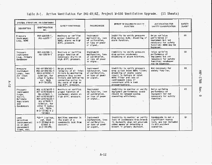
Table A-1. Active Ventilation for 241-AY/AZ, Project W-030 Ventilation Upgrade. (11 Sheets) - - SAFETY CLASS'
JUSTIFICATION FOR SAFEN CLASSIFICATION
SYSTEM, STRUCTURE. OR COMPONENT EFFECT OF FAILURE ON SAFEN FUNCTION SAFEN FUNCTION61 FAILURE MODE
DESCRIPTION IDENTIFICATION NO
GS Pressure Instrument Loop, HEME
PDT-AZKIOP-1, PDI-AZK19-1
I n a b i l i t y t o v e r i f y pressure drop across HEME; d isabl ing o f alarm function.
Helps optimize performance o f equipment but not necessary f o r safety function; HEME may be bypassed.
Helps optimize performance of equipment but not necessary f o r sa fe ty function; condenser may be bypassed.
Not necessary f o r sa fe ty function.
Monitors o r ve r i f i es proper funct ion o f HEME; alarms on high d i f f . pressure.
Monitors or v e r i f i e s proper funct ion o f condenser; alarms on high d i f f . pressure.
Instrument malfunction, loss of ca l ibrat ion, or loss o f power or signal.
Instrument malfunction, loss o f ca l ibrat ion, or loss of power or s ignal .
- GS I n a b i l i t y t o v e r i f y pressure
drop across condenser; d i sab l i ng o f alarm funct ion.
Pressure Instrument Loop, Primary Condenser
PDT-AZKlO8-1, PDI -AZK18-1
- GS Pressure
Instrument Loops, Tank A i r I n l e t F i l t e r s
PDI-AY101K103-1 PDI-AY101K104-1 PDIS-AYIOIKI-1 (s imi lar , f o r
other 3 tanks; re f . P&ID
H-2-131075)
Instrument malfunction, loss of ca l i b ra t i on , or loss of power or s ignal .
I n a b i l i t y t o v e r i f y pressure drop across i n l e t HEPA f i l t e r ; d i sab l i ng o f alarm; could resu l t i n f a i l u r e o f i n l e t HEPA f i l t e r and loss o f confinement (on ly i f concurrent w i th a tank pressur izat ion) .
I n a b i l i t y t o monitor or v e r i f y equipment performance; could resu l t i n reduced system operating ef f ic iency.
Helps protect i n t e g r i t y of a i r i n l e t f i l t e r s by monitoring pressure drop across f i l t e r s and i n i t i a t i n g correct ive act ion i n the event o f h igh or law d i f f . pressure.
Monitors o r v e r i f i e s proper funct ion o f condenser; alarms on h igh d i f f . pressure.
I z -rl I
v b-
m m
W (D <
0
- GS
~
Instrument malfunction, loss of ca l i b ra t i on , o r loss o f power o r signal.
Helps optimize performance o f equipment but not necessary f o r sa fe ty function.
Pressure Instrument LOOPS, Recirc. Moi Sture Separators and Condensers
PDE-AYlOlK405-1 PDT-AY101K405-1 PDI -AYlK45-1,
PDE-AY101K408-1 PDT-AY101K408-1
PDI-AYlK48-1 (s imi lar , f o r
other 3 tanks; ref. P&lDs
H-2-131062-H-2- 131065) -
GS Not i f i es operator i n the event of a condensate leak from ductwork.
Instrument malfunction, loss o f ca l ibrat ion, o r loss o f power or s ignal .
I n a b i l i t y t o monitor o r v e r i f y loss o f condensate from breach i n ductwork; does not preclude other means o f detect ing a breach i n primary ductwork.
Condensate i s not a s ign i f i can t source term, and not inc luded i n BIO accident scenarios.
Leak detect ion inst rumentat i on on duct encasement l ines, etc.
A-12

SYSTEM, STRUCTURE, OR COMPONENT SAFETY FUNCTIONlSI
. IDENTIFICATION NO.
3 z ll I + -4 m m
W
C
0
EFFECT OF FAILURE ON SAFETY JUSTIFICATION FOR SAFETY FUNCTION SAFETY CLASSIFICATION CLASS' FAILURE MODE
A-1.3

Table A-2. Ventilation CAM Interlock f o r 241-AY/AZ, Project W-030 Ventilation Upgrade. (2 Sheets)
FUNCTIONAL REQUIREMENTS
The CAM must operate cont inuously whi le the exhaust system i s operating, maintaining isok ine t ic sampling conditions. The CAM must measure the rad ia t ion l eve l i n the sampled f l o w stream and detect leve ls i n excess o f a preset level . The CAM s h a l l ac t i va te an in te r lock t o shut down the exhauster, o r switch exhaust t ra ins , w i t h i n 10 minutes o f detect ing an excess rad ia t ion level . Upon CAM fa i lu re , the monitors must actuate an alarm and an in te r lock t o shut down the exhaust system.
whi le the exhaust system i s operating, and must be capable o f alarming and shut t ing down the exhaust fan when rad ia t ion Levels above background are detected i n the stack.
The stack CAM must operate cont inuously
SYSTEM lOENTlFlCATlON CLASSIFICATION
ss
sc
241-AYrAZ Tank Farm Act ive V e n t i l a t i o n CAM I n t e r l o c k System ( located on 296-A-42 Primary Exhaust Stack), r e f . P&ID H-2-131078.
EFFECT OF FAILURE ON SAFETY FUNCTION
SAFEN FUNCTIONIS)
JUSTIFICATION FOR SAFEN CLASSIFICATION
Prevents an u n f i l t e r e d release from occurr ing for more than 10 minutes
Fa i led CAM w i l l not shut down the ac t ive v e n t i l a t i o n system i n the event o f a f a i l e d HEPA f i l t e r , r e s u l t i n g i n an unmonitored, u n f i l t e r e d release o f radioact ive par t i cu la te .
Ensures exhaust fan i s shut down or switched i n the event exhaust HEPA f i l t e r s break through; prevents u n f i l t e r e d aerosol release t o the atmosphere.
BIO Sec. 5.3.2.20, Spray Leak i n Structure; C r i t e r i a 14.
THE ITEMS LISTED BELOW ARE UNIQUE <
SYSTEM, STRUCl
DESCRIPTION
BetarGama Radioact ive P a r t i c u l a t e Monitor Instr. Loop and in te r lock t o fans
Vacuum Pumps
E. OR COMPONENT
IDENTIFICATION NO.
RE-AZK1-1 & RIAS-AZKI-1
AZ-K1-11-1 & AZ-K1-11-2
UPONENTS THAT MAKE UP T
SAFETY FUNCTION(S1
_____~
Monitors f o r rad ia t ion i n exhaust stream, and in te r locks t o shut down fan
Draw sample from exhaust stream
SAFEN SSC
FAILURE MODE
Malfunct ion caused b y excessive moisture i n sample l i n e or h igh temperature, loss o f Ca l i b r a t ion.
Fa i lu re of motor due t o heat ing o r loss o f power; mech. f a i l u r e o f pump.
JUSTIFICATION
HNF-SD-WM-BID-001, Rev. 0, (BIO) Sec. 5.3.2.2, HEPA F i l t e r Fai lure; Safety SSC C r i t e r i a 6.
HNF-SD-WM-BIO-001, Rev. 0, @IO) Sec. 5.3.2.20, Spray Leak i n St ruc ture o r Overground Waste Transfer Line; C r i t e r i a 1.
Loss o f sample stream t o CAM, o r loss o f consistent sample gas f low rate; f a i l u r e o f CAM t o detect radioact ive p a r t i c u l a t e and shut down exhauster i n the event o f a HEPA f i l t e r fa i lu re . I
BIO Sec. 5 Spray Leak Structure; 14.
.3.2.20, i n C r i t e r i a
- - SAFETY ,
CLASS'
- __ sc
sc
-
I z -n
-4 m m w
W <
0
A-14

Table A-2. Ventilation CAM Interlock for 241-AY/AZ, Project W-030 Ventilation Upgrade. (2 Sheets)
FLow Regulator (MOV)
SYSTEM, STRUCTURE, OR COMPONENT SAFETY FUNCTIONIS) FAILURE MODE
MV-AZKI-1 Regulates constant Mechanical or sample fLow through elec. f a i l u r e of CAM system valve actuator
switch, Loss of FAL-AZKI-1A c a l i b r a t i o n
EFFECT OF FAILURE ON SAFEN FUNCTION
Continued operation of v e n t i l a t i o n system without CAM function, f a i l u r e t o shut down a c t i v e v e n t i l a t i o n i n the event of a f a i l e d HEPA f i l t e r , r e s u l t i n g i n an unmonitored, u n f i l t e r e d release of rad ioac t ive par t i cu la te .
F a i l u r e of regu la to r i s normally detected by the flow alarm switch, r e s u l t i n g i n c o r r e c t i v e a c t i o n t o restore system t o operation.
JUSTIFICATION FOR SAFETY CLASSIFICATION
B I O Sec. 5.3.2.20, Spray Leak i n Structure; C r i t e r i a 14.
FLow alarm switch provides sa fe ty function; f a i l u r e o f regulator w i l l not a f f e c t sa fe ty funct ior of system.
- - SAFETY CLASS'
- - sc
GS
-
* SC = Safety Class; Assignments based 610 analyses and "SSC C r i t e r i a " i n HNF-PRO-516 (formerly Sec. 9.0 of WHC-CM-4-46, Safety Analyses Manual, Westinghouse Hanford Company, Richland, Washington); see Table 2 i n Sec. 3.1, t h i s SEL.
SS = Safety Signif icant; GS = General Service (not sa fe ty re la ted) .
A-15

HNF-1788 Rev. 0
APPENDIX B
SAFETY CLASS UPGRADE SUMMARY TABLE
B- 1
SAFETY CLASS UPGRADE SUMMARY TABLE
W
N
EQUIPMENT IDENTIFICATION
NUMBER
241 -AZ-702
241 -AZ-701
241-AY-401, 241 -AY-402, 241-AZ-401, 241 -AZ-402
MK-AYIOIKI-1 MK-AYIOZKI-1 MK-AZlOlKI-1 MK-AZIOZK1-I
Ducting Housings Struct . Frame Base
DESCRIPTION
Vent i la t ion Bui ld ing
Generator Bui ld ing
Recirculat ion and Cooling Cel l Bldgs.
Primary tank vent system A i r I n l e t Stat ions
Pressure Control Valves. But ter f ly , 6". e l e c t r i c a l l y operated.
Tubing, ASTM A269. 304 Sheet, 12 Ga., SST ASTM A240 304 Channel, ASTM A36, CS Channel, ASTM A36, CS
The above components were supplied with the four A i r I n l e t Stat ions designed and b u i l t vendor; re fer t o CVI#22525, Supp 98.
SPECIFICATION
W-03O-CZ
W-030-P5
CLASSIFICATION
ss
ss
sc
sc
- MEETS
- - GS*
GS*
GS*
ss*
sc
COMMENTS
Designed t o SS loads, procured t o GS requirements. Cert. of Compliance (COC) i n vendor submittal 85; design anal. i n submittal 162. *See also discussion, Sec. 3.0 & 4.0.
Designed t o SS loads, procured t o GS requirements. Design anal. i n vendor submittal 162. *See also discussion, Sec. 3.0 & 4.0.
Designed t o SS loads, procured t o GS requirements. *See also discussion, Sec. 3.0 & 4.0.
*See discussion of valves, Sec. 3.0 & 4.0.
E n t i r e a i r i n l e t S t a t i o n procured and q u a l i f i e d per spec. as an assembled u n i t . COC from vendor i n CVI#22525, Supp. 94, s t a t i n g a l l requirements of spec. have been met. CMTRs f o r the s t e e l used t o f a b r i c a t e the s ta t ions are i n CVI#22525, Supp 94, design analysis i n CVI#22525, Supp 91.
I z ll
c -4 co co
P
5 0
B-2

W
W
I z 7l
c U m
EQUIPMENT IDENTIFICATION
NUMBER
W-AY1100-M9 W-AY2100-M9 W-AZ1100-M9 W-AZ2100-M9
Y-AY1101 -M9 W-AY2101-M9 W-A21101 -M9 W-AZ2101-M9 W-AY1102-M9 V-AZ2102-M9 V-AZ100-M9
V-AZ103-M9
Hangers Supports
MK-AZKIOB-IC MK-AZKl09-IC
MK-AZK108-1A MK-AZK108-18 MK-AZKlO9-1A MK-AZK109-1B
DESCRIPTION
Primary tank vent system
Piping i n t o the waste tanks f r o m the A i r I n l e t Stat ions.
Piping out of waste tanks (bypass mode) f r o m r e c i r c u l a t i o n vent cool ing modules.
Pipe: Sched 40s. SST ASTM A312 G r TP 304L. F i t t i n g s : SST ASME SA 403 Class UP-S 304L. See p ipe code M-9 of W-030-C3, Section 15493.
Cel l p ip ing (condenser and HEME bypassed). Pipe: Sched 40s. SST ASTM A312 TP 304L. F i t t i n g s : SST ASTM A403 WP 304L. Flanges: CL 150# Forged SST ASTM A182 F304L. See pipe code M-9 of W-030-C2, Section 15493.
See Para. 2.2.9, Sec. 15500, W-030-C2
Cel l va lv ing (condenser and HEME bypassed). B u t t e r f l y , I O " , wafer style, CL 150# SST body, stem and disc, bubble t i g h t . Remote operator. See pipe code M-9 of W-030-C2, Section 15493.
Cel l i s o l a t i o n valving (condenser and HEME bypassed). B u t t e r f l y , I O " , wafer s ty le , CL 150# SST body, stem and disc, bubble t i g h t . Remote operator. See p ipe code M-9 o f W-030-C2, Section 15493.
SPECIFICATION
W - 030- C3
W-030-C2
U-030-C2
CLASSIFICATION
bquired per 810
- -
sc
sc
sc
sc
sc
sc
- MEETS
- -
sc
sc
sc
GS*
ss*
ss*
COMMENTS
CMTRs from q u a l i f i e d supp l ie rs i n vendor submittal 5.
CMTRs from q u a l i f i e d supp l ie r i n vendor submittal 130.
Procured GS; no documentation t o show that hangers and supports meet SC procurement requirements. *See discussion of hangers and supports, Sec. 3.0 & 4.0.
COC from the prime contractor f o r constr. spec., f o r valve bodies and bonnets, i n Submittal 132.
COC from prime constr. contractor, Sub. 132. Meets i n t e n t of o r i g i n a l SS, p rov id ing confinement.
*See discussion o f valves, Sec. 3.0 & 4.0.
0 I
B-3

W
P
EQUIPMENT IDENTIFICATION
NUMBER
FE-AYlOIK1-2, FT-AYlOIK1-2, & FIC-AYIKI-2 ( s i m i l a r , for other 3 tanks; ref. P&ID H-2-131075)
RE-AZK109-1 & RIAS-AZK109-1
Ducting Housing
Support Frame
MK-AZKI-1A MK-AZKI-1B MK-AZKl-2A MK-AZK1-28
MK-AZK105-1A1 MK-AZKIO5-161
DESCRIPTION
Tank A i r Flow Ind icat ion & Control Instrument Loop (Tank Exhaust Outlet); i n c l . f low ind icator cont ro l lers , located i n loca l cont ro l u n i t s (LCUs) 1 & 2, E / l Rooms, Bldg. 241-AZ-702.
HEME Radiation Monitor Instrument Loop
Primary tank vent system, F i l t e r Tra in D iv ing
See pipe code M-9, Sec. 15493.
Duct: Sched 10s. SST ASTM A312 TP 304L. F i t t ings: SST ASTM A403 Class CR 304. Flanges: sl ip-on, l i g h t weight, SST. See duct code 0-3 of W-030-C2, Section 15500.
Primary tank vent System, F i l t e r Trains
300 series SST
CS, ASTM A36
Valve, b u t t e r f l y , 10". flanged, CL 150# SST with e l e c t r i c actuators.
I O " But ter f l y valves, SST, manually operated.
SPECIFICATION
W-030-P27 & WHC-S-4013
W-030-P25
W-030-C2
W-030-P3
CLASSIFICATION
ss
sc
sc
sc
sc sc
sc
- MEETS
- - ss*
GS*
sc
GS*/SC
sc
sc
ss*
ss*
COMMENTS
Instrument loops use in te r face wi th MCS and a lso provide l o c a l readout independently of MCS. LCU cabinets and instruments q u a l i f i e d t o SS. QAP i n Submittal 5, Environ. & seismic q u a l i f i c a t i o n doc. i n
*See discussion, Sec. 3.0 & 4.0. cv1#22525 supp. 48.
Instruments depend on i n t e r f a c e wi th MCS t o perform SS safe ty func t ion per 610. System was procured t o GS, with GS (UBC) seismic requirements. C e r t i f i c a t e of c a l i b r a t i o n i n CVI#22525, Supp. 69. *See discussion, Sec. 3.0 & 4.0.
CMTRs i n vendor submi t ta l 130.
NO CMTRs f o r sched 10s materials.
* Ductwork upstream o f f i l t e r s (V-A2102 & V-AZ103) procured SS as p a r t o f f i t t e r t r a i n p ip ing, per W-030-P3; remaining ductwork, downstream of f i l t e r s , outside confinement boundary, procured GS. See a lso discussion, Sec. 3.0 & 4.0.
*See discussion on valves, Sec. 3.0 & 4.0.
TWO f i l t e r t r a i n s procured as u n i t assemblies w/ vendor c e r t i f i e d documentation. CVI#22525, Supp. 113 contains COC from vendor s t a t i n g a l l requirements o f W-030-P3 have been met, a lso separate COCs f o r valves, CMTRs f o r ducting, housing and frame materials. Vendor submi t ta l 6 contains Leak t e s t data.
F i l t e r t r a i n valves meet i n t e n t of o r i g i n a l S S , based on confinement.
8-4
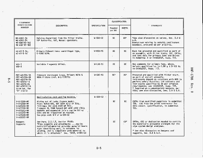
W
cn
EQUIPMENT IDENTIFICATION
NUMBER
AZ-Kl-5-1A.. AZ-K1-5-16
VSD - I VSD-2
PDT-AZK104-1A POT-AZK104-2A POT-AZK110-1A PDI-AZK14-1A PDI-AZK14-2A PDI-AZK110-1A (s im i la r , f o r ' E ' t r a i n )
V-AYl200-M9 V-AY2200-M9 V-AZ1200-M9 V-AZ2200-M9 V-AY1203-M9 V-AY2203-M9 V-AZ1203-M9 V-AZ2203-M9
Hangers Supports
DESCRIPTION
ilalving downstream from the f i l t e r t ra ins . 10" bu t te r f l y , SST, Manual operators.
Primary Exhaust Fans: cen t r i f uga l type, 0-1000 SCFM.
Variable frequency drives.
Pressure instrument Loops, Primary HEPA & HEGA F i l t e r s ( re f . H-2-131076)
Reci rcu lat ion vent cooling modules.
P ip ing out of tanks (bypass mode). Pipe: Sched 40s. SST ASTM A312 TP 304L. F i t t i ngs : SST ASTM A403 UP 304L. Flanges: CL 150# Forged SST ASTM A182 F304L Gaskets and expansion j o i n t s may be C G I w/ COCs and QC inspection on receipt. See p ipe code M-9 of W-030-C2
See Para. 2.2.1.3, Section 15493: "Pipe supports and attachments .... may be noncer t i f ied mater ia l provided material bears type i den t i f y i ng mark, i s su i tab le fo r welding, and i s compatible wi th mater ia l t o which i t i s attached." Sec. 15493, W-030-C2
SPECIFICATION
W-030-C2
W-030-P3
W-030-P3
W- 030 - P3
W-030-C2
CLASSIFICATION
lequired per 010
- - sc
sc
sc
- sc*
-
sc
sc
- MEETS
- - GS*
sc
sc
-
sc
GS*
COMMENTS
*See a lso discussion on valves, Sec. 3.0 & 4.0. Downstream valv ing i s outs ide confinement boundary, procured GS per W-030-C2.
Each fan procured and q u a l i f i e d as p a r t of an assembly, w i th f i l t e r t ra in ; COC, CMTRs, and t e s t data f o r primary fans and d r i ves i n Submittal 6 o r CVI#22525, Supp. 113.
See comnents f o r primary fans, above. Seismic q u a l i f i c a t i o n t o 0.50 g 6l 3-100 Hz i n CVI#22525, Supp. 113.
Procured and q u a l i f i e d wi th f i l t e r t ra in , as p a r t of ove ra l l assembly. instruments depend on in te r face w i th MCS t o perform safety function; LCU cabinets and instruments q u a l i f i e d t o SS per o r i g i n a l requirements; see CVI#22525, Supp. 113. * Required as a compensatory measure, per TSRs; see also discussion, Sec. 3.0 & 4.0.
CMTRs from q u a l i f i e d supp l i e rs i n submi t ta l 130. t h i s constr. spec i f icat ion, i n submi t ta l 132.
COC from the prime contractor f o r
CMTRs, COC o r dedicat ion needed t o c e r t i f y the mater ia l 's allowable s t reng th f o r the p ipe system design analyses.
* See a lso discussion on hangers and supports, Sec. 3.0 & 4.0.
8-5

EQUIPMENT IDENTIFICATION
NUMBER
HK-AY101K4-4 HK-AY102K4-4 MK-AZ101K4-4 MK-AZ102K4-4
MK-AY1O1KI-ZA1 MK-AY102K1-2Al M K - A Z l O l K 1 - 2 A I MK-AZ102Kl -ZAl MK-AYlOIK1-2A2 MK-AYlOZK1-2A2 MK-AZlOIK1-2A2 MK-AZlOZKl -2A2 MK-AYlOIK1-2A3 MK- AY1 02K1-2A3 MK-AZIOIKI -2A3 MK-AZ102K1-2A3 MK-AYIOlK4-1 MK-AY102K4-1 M K - A Z l O l K 4 - 1 MK-AZ102K4-1 MK-AY101K4-2 MK-AY102K4-2 MK-AZ101K4-2 MK-AZ102K4-2 MK-AY101K4-3 MK-AY102K4-3 MK-AZ101K4-3 MK-AZ102K4-3
RE-AZK1-1 & R I A S - A Z K I - 1
A Z - K 1 - 1 1 - 1 & A Z - K 1 - 1 1 - 2
DESCRIPTION
Recirc. vent cooling modules, cont'd.
Valving out of tanks (bypass mode). Butterfly, 8". wafer style, CL 150# SST body, stem and disc, bubble tight. With remote operators. See pipe code M-9, Section 15493.
Isolation valving (bypass mode). Butterfly, 8" & IO", wafer style, CL 1 5 0 # SST body, stem and disc, bubble tight. ALL with remote operators. See pipe code M-9 of W-030-C2, Section 15493.
Stack Monitoring System
Beta/Gama Radioactive Particulate Monitor Instr. Loop and CAM Interlock to fans
CAM Vacuum Pumps
SPECIFICATION
W-030-C2
U - 0 3 O - P l 6
B-6
CLASSIFICATION
7equired per BIO - -
sc
sc
-
sc
sc
-
- MEETS
- -
ss*
ss*
-
ss
sc
-
COMMENTS
See also general discussion on valves, iec. 3.0 & 4.0.
lalving meets SS based on confinement.
:OC from prime constr. contractor, stating /alve bodies and bonnets, expansion joints tnd gaskets comply with the specifications 3nd drawings, in CVI#22525, Supp. 113.
:OC from prime constr. contractor for valve iodies and bonnets in CVI#22525, Supp. 113.
>AP in vendor submittal 2.
:AM Interlock depends on interface with MCS to perform safety function; LCU cabinets snd instruments qualified to SS.
See also discussion, Sec. 3.0 & 4.0.
'umps ordered per specification as part of zntire sampling system; pumps are an sngineered item and meet requirements for j C .
I z T
I c-l
-4 00 00
W C
0

W
v
EQUIPMENT IDENTIFICATION
NUMBER
FE-AZK1-1, FIT-AZK1-1, UC-AZKI-2, & FAL-AZKI-1A
LCU-1 & tcu-2
Wiring
Breakers
Diesel generator
Breakers
ATS-1 ATS-2
UPS-1 UPS-2 UPS-3
Wiring
ATS-3
Supply Tank
DESCRIPTION
CAM Flow Alarm Switch I n s t r . Loop
MCS Instrument In ter face Cabinets
Power S U D P ~ Y - Normal
600V, Type TC, Hypalon or PVC jacket
500A, 400A, and 225A t r i p , UL l i s ted .
Power SUPDIY - Backue
125 kW
600 V, 3 pole, 200A t r i p , UL l i s t e d
480 VAC, 225A. 3 PH, 4 W
8 kWf10 KVA Rating
600V, Type TC, Hypalon o r PVC jacket
480 VAC, 60 A, 3 PH, 3 W, U t l i s t e d
300 gal capacity wi th secondary containment.
SPECIFICATION
WHC-S-4013
W-030-CZ
W-030-Pll
W-030-Pl7
W-030-C2
W-030-C2
W-030-P24
CLASSIFICATION
sc
sc
sc
sc
sc
sc
sc
sc
sc
COMMENTS - MEETS
Procured as p a r t of e n t i r e sampling system; instruments are hardwired and do not depend on in te r face w i th MCS t o perform safety funct ion.
Assembled cabinets q u a l i f i e d t o SS, i nc l . 0.12 g DBE, based on vendor t e s t report. ss I
ss*
GS*
* See a l so d iscuss ion o f elec. power supplies, Sec. 3.0 & 4.0. Power cable dedicated i n Design Analysis W-030-086 w i th rece ip t inspect ion i n vendor Submittal 175 ( C G I dedicat ion) .
ss*
ss* ss*
ss*
ss* ss*
ss*
* See a l so d iscuss ion of elec. power supplies, Sec. 3.0 & 4.0. Qua l i f i ed t o SS requirements, see vendor submi t ta l 4. System includes d iese l generator, breakers and ATS-1 & -2.
UPSs dedicated for SS use i n Design Analysis W-030-89. See CVI#22525, Supp. 16.
GGI Dedicat ion fo r wi re i n W-030-86. w l rece ipt inspect ion i n submi t ta l 175.
CMTRs and design analyses f o r tank i n CVI#22525, supp. 34.
I z 7
+ U W W
P (D <
0
B- 7

To From
D i s t r i b u t i o n JR K r i s k o v i c h
Project Title/Work Order 241-AY/AZ P r o j e c t W-030 V e n t i l a t i o n Upgrade; HNF-1788, P r o j e c t W-030 S a f e t y C lass Upgrade Summary Report .
WM H a r t y Jr MN Islam JR K r i s k o v i c h (?x&/).&) CE Leach KH M o r r i s RB Pan MA Payne RE Raymond GE Rensink SH R i f a e y RL Sch losser JA Tuck JJ Verderber SU Zaman C e n t r a l F i l e s
Page 1 of 1 Date 13 February 1998 EDT No. 618224 ECN No.
S5-13 X S5-12 X R1-56 X R1-49 X R1-49 X H5-57 X R2-58 X R2-38 X S2-24 X R1-56 X R1-56 X S2-24 X S5-15 X S5-12 X A3-88 X
Text Text Only Name MSlN With All
Attach.
A-6000-135 (01/93) WEF067
Attach./ EDT/ECN Appendix Only
Only