Embed Size (px)
Citation preview
Pairings™ 1
Proper product installation, in accordance with these instructions, is the responsibility of the installing agent. If you have any questions concerning these instructions, please call Kimball Office Customer Care.
Part 2894306 Revision A
Assembly Instructions
Lounge/Bench/Perch to Wall Assembly
Tools Required
Hardware Required
• Phillips #3 Screwdriver
• Rubber mallet
Note: Proper installation is critical to prevent dam-age and ensure stability. 1. Make sure all electrical components (if present)
installed inside the Wall before assembling the Lounge/Bench/Perch to the Wall.
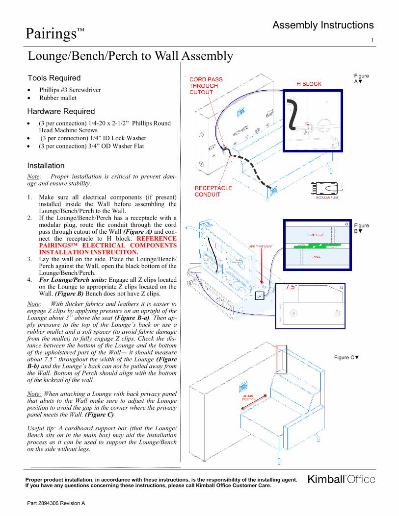
2. If the Lounge/Bench/Perch has a receptacle with a modular plug, route the conduit through the cord pass through cutout of the Wall (Figure A) and con-nect the receptacle to H block. REFERENCE PAIRINGS™ ELECTRICAL COMPONENTS INSTALLATION INSTRUCITON.
3. Lay the wall on the side. Place the Lounge/Bench/Perch against the Wall, open the black bottom of the Lounge/Bench/Perch.
4. For Lounge/Perch units: Engage all Z clips located on the Lounge to appropriate Z clips located on the Wall. (Figure B) Bench does not have Z clips.
Note: With thicker fabrics and leathers it is easier to engage Z clips by applying pressure on an upright of the Lounge about 3” above the seat (Figure B-a). Then ap-ply pressure to the top of the Lounge’s back or use a rubber mallet and a soft spacer (to avoid fabric damage from the mallet) to fully engage Z clips. Check the dis-tance between the bottom of the Lounge and the bottom of the upholstered part of the Wall— it should measure about 7.5” throughout the width of the Lounge (Figure B-b) and the Lounge’s back can not be pulled away from the Wall. Bottom of Perch should align with the bottom of the kickrail of the wall. Note: When attaching a Lounge with back privacy panel that abuts to the Wall make sure to adjust the Lounge position to avoid the gap in the corner where the privacy panel meets the Wall. (Figure C) Useful tip: A cardboard support box (that the Lounge/Bench sits on in the main box) may aid the installation process as it can be used to support the Lounge/Bench on the side without legs.
Installation
• (3 per connection) 1/4-20 x 2-1/2” Phillips Round Head Machine Screws
• (3 per connection) 1/4” ID Lock Washer
• (3 per connection) 3/4” OD Washer Flat
Figure A▼
Figure B▼
Figure C▼
Pairings™ 2
Proper product installation, in accordance with these instructions, is the responsibility of the installing agent. If you have any questions concerning these instructions, please call Kimball Office Customer Care.
Part 2894306 Revision A
Assembly Instructions
5. Make sure the Lounge/Bench/Perch seams are in line with appropriate seams of the Wall. Disengage Z clips (for Lounge units), adjust the alignment and repeat the operation 4 if necessary.
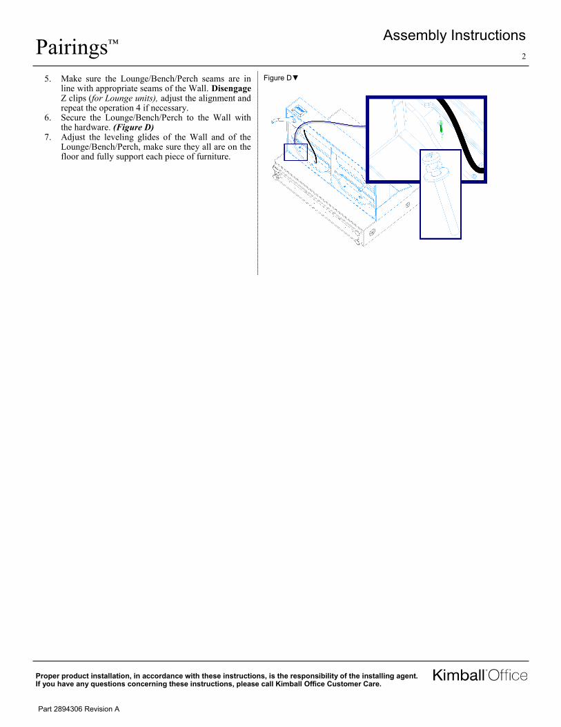
6. Secure the Lounge/Bench/Perch to the Wall with the hardware. (Figure D)
7. Adjust the leveling glides of the Wall and of the Lounge/Bench/Perch, make sure they all are on the floor and fully support each piece of furniture.
Figure D▼