Embed Size (px)
Citation preview
PALESTINE POLYTECHNIC UNIVERSITYCollege of Administrative sciences and Informatics
Department of Information Technology
Data communications and networks William Stallings
Data and Computer Communications7th Edition
Slides modified and updated by:
Dr. Mohammed Aldasht and Dr. Mahdi Nasereddin
Summer 2006
William StallingsData and Computer Communications7th Edition
Chapter 1Data Communications and Networks Overview
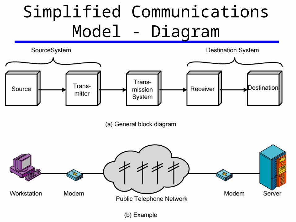
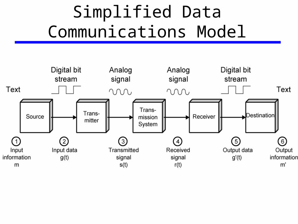
A Communications Model• Source: generates data to be transmitted, examples are
telephones and personal computers.
• Transmitter: converts data into transmittable signals;—e.g. the modem takes a digital bit stream from an attached device such as
a PC and transforms that bit stream into an analog signal that can be handled by the telephone network.
• Transmission System: carries data, this can be a single line or a complex network connecting source and destination.
• Receiver: converts received signal into data;—e.g. a modem will accept an analog signal coming from a network or
transmission line and convert it into a digital bit stream.
• Destination: takes incoming data from the receiver.
Communications Tasks I• Transmission system utilization: refers to the need to make
efficient use of transmission facilities that are typically shared among a number of communicating devices.—Multiplexing.
—Congestion control.
• Interface: to communicate, a device must interface with the transmission systems. Most systems use electromagnetic signals.
• Signal generation: the form and intensity of the signal must be capable of being propagated through the transmission systems and interpretable as data at the receiver.
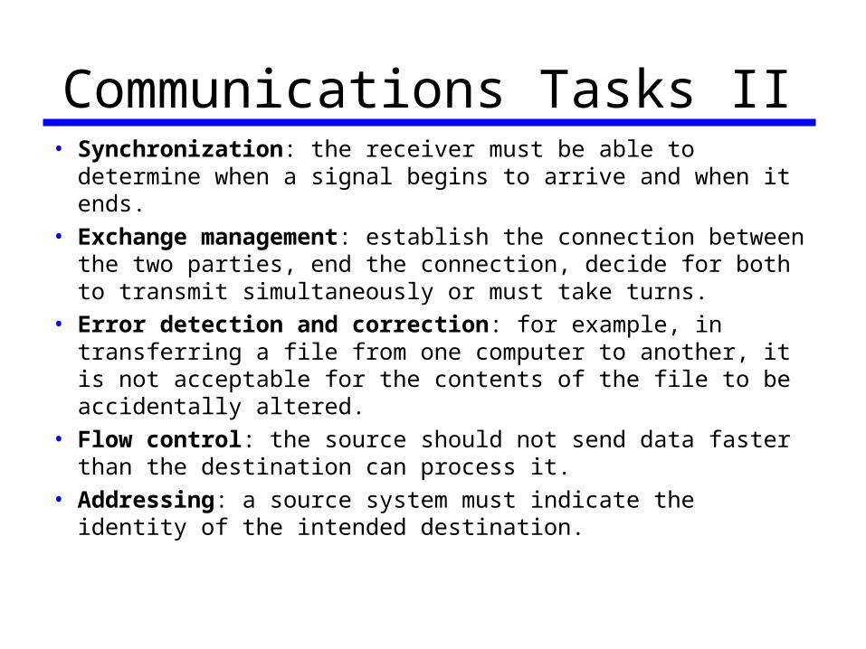
Communications Tasks II• Synchronization: the receiver must be able to determine
when a signal begins to arrive and when it ends.
• Exchange management: establish the connection between the two parties, end the connection, decide for both to transmit simultaneously or must take turns.
• Error detection and correction: for example, in transferring a file from one computer to another, it is not acceptable for the contents of the file to be accidentally altered.
• Flow control: the source should not send data faster than the destination can process it.
• Addressing: a source system must indicate the identity of the intended destination.
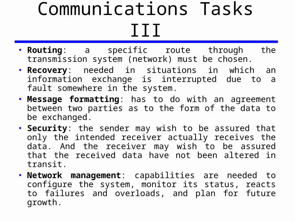
Communications Tasks III• Routing: a specific route through the transmission system
(network) must be chosen.• Recovery: needed in situations in which an information
exchange is interrupted due to a fault somewhere in the system.
• Message formatting: has to do with an agreement between two parties as to the form of the data to be exchanged.
• Security: the sender may wish to be assured that only the intended receiver actually receives the data. And the receiver may wish to be assured that the received data have not been altered in transit.
• Network management: capabilities are needed to configure the system, monitor its status, reacts to failures and overloads, and plan for future growth.
Simplified Communications Model - Diagram
Simplified Data Communications Model
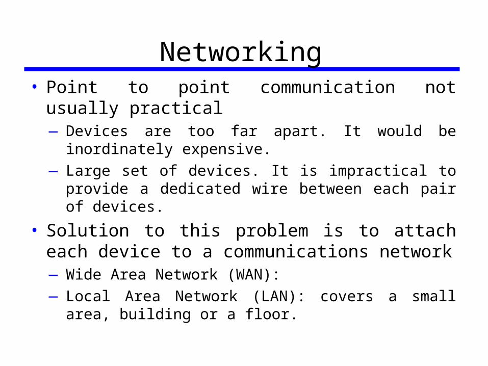
Networking• Point to point communication not usually practical
—Devices are too far apart. It would be inordinately expensive.
—Large set of devices. It is impractical to provide a dedicated wire between each pair of devices.
• Solution to this problem is to attach each device to a communications network—Wide Area Network (WAN):
—Local Area Network (LAN): covers a small area, building or a floor.
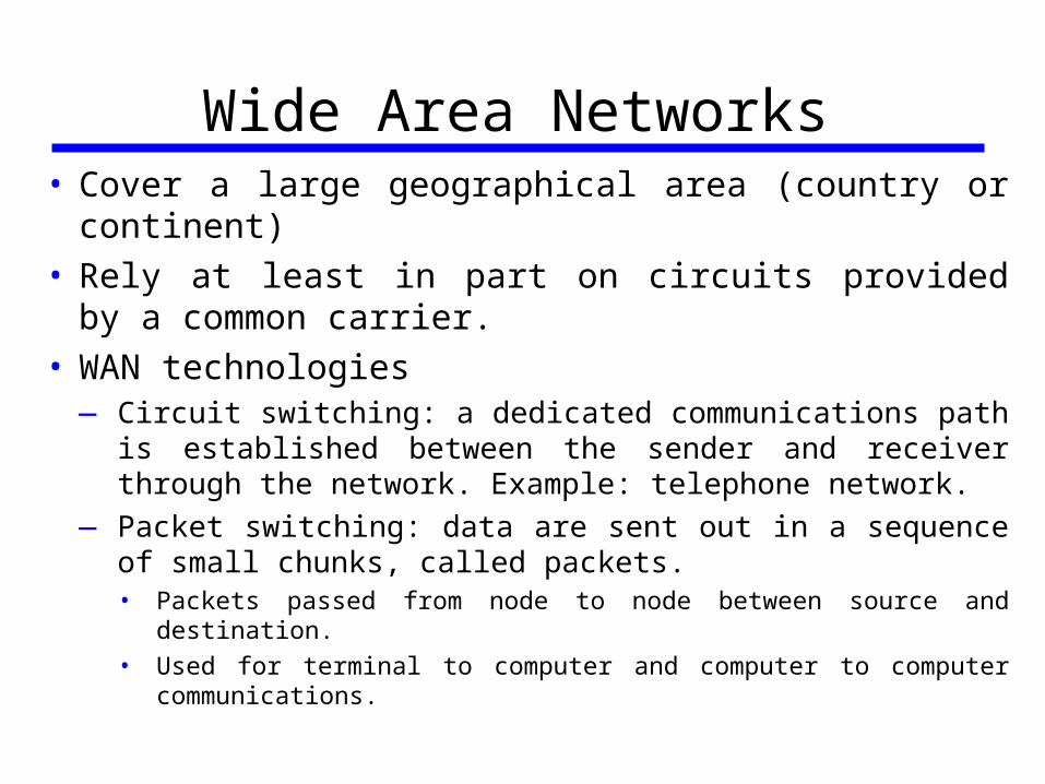
Wide Area Networks• Cover a large geographical area (country or continent)• Rely at least in part on circuits provided by a common
carrier.• WAN technologies
—Circuit switching: a dedicated communications path is established between the sender and receiver through the network. Example: telephone network.
—Packet switching: data are sent out in a sequence of small chunks, called packets.
• Packets passed from node to node between source and destination.
• Used for terminal to computer and computer to computer communications.
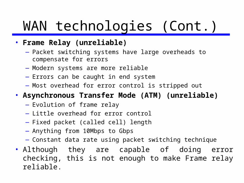
WAN technologies (Cont.)• Frame Relay (unreliable)
—Packet switching systems have large overheads to compensate for errors
—Modern systems are more reliable
—Errors can be caught in end system
—Most overhead for error control is stripped out
• Asynchronous Transfer Mode (ATM) (unreliable)—Evolution of frame relay
—Little overhead for error control
—Fixed packet (called cell) length
—Anything from 10Mbps to Gbps
—Constant data rate using packet switching technique
• Although they are capable of doing error checking, this is not enough to make Frame relay reliable.
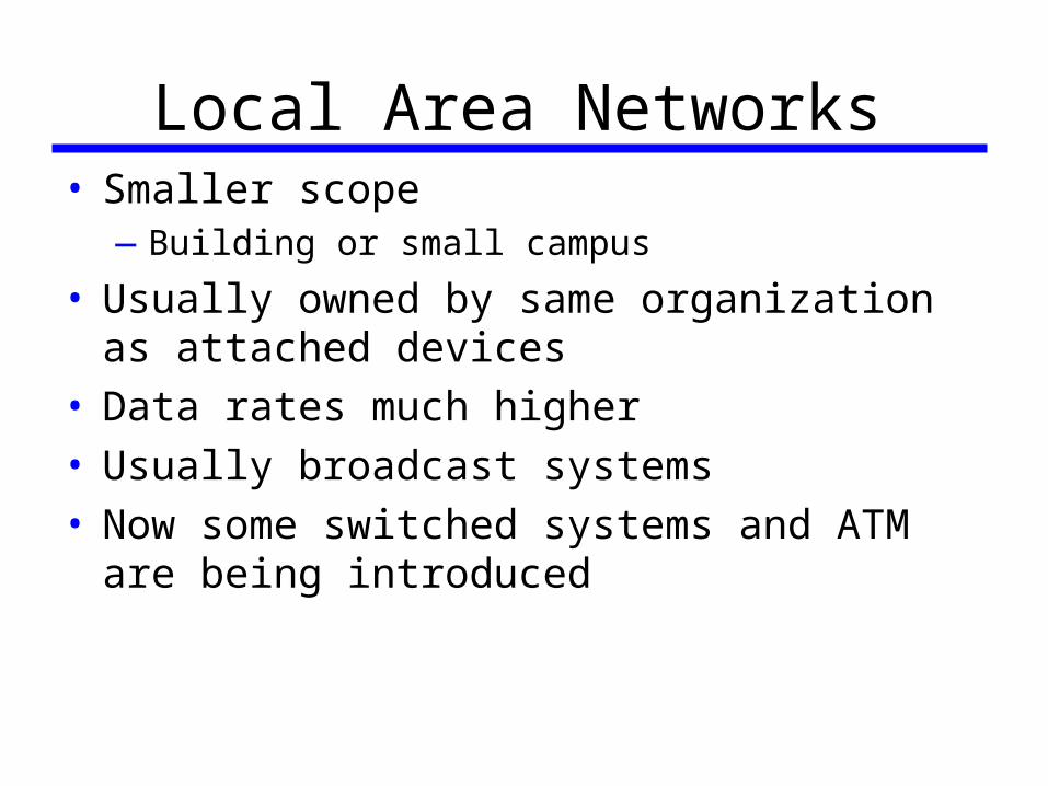
Local Area Networks• Smaller scope
—Building or small campus
• Usually owned by same organization as attached devices
• Data rates much higher• Usually broadcast systems• Now some switched systems and ATM are being
introduced
LAN Configurations• Switched
—Switched Ethernet LAN: which may consist of a single switch with a number of attached devices, or a number of interconnected switches.
—ATM LAN: ATM network in a local area.
• Wireless—Widely used in business environments.
—Advantages:• Mobility
• Ease of installation
Metropolitan Area Networks• MAN: occupies a middle ground between LANs and
WANs.• Point-to-point and switched network techniques used
in WANs may be inadequate for the growing needs of the organizations.
• Recently, wireless networks and metropolitan extensions to Ethernet have been implemented in MANs.
• A MAN in intended to provide the required capacity at lower costs and greater efficiency than obtaining an equivalent service from the local telephone company.
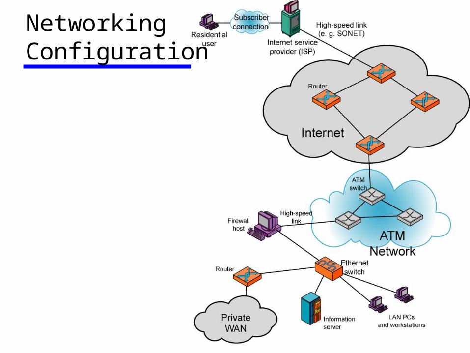
NetworkingConfiguration
William StallingsData and Computer Communications 7th Edition
Chapter 2Protocols and Architecture
Addressing Requirements• Two levels of addressing required• Each computer needs unique network address• Each application on a (multi-tasking) computer needs
a unique address within the computer—The service access point or SAP (port on TCP/IP stacks)
Protocol Data Units (PDU)• The combination of data from the next higher layer and
control information is known as a PDU.• At each layer, protocols are used to communicate• Control information is added to user data at each layer• e.g.
—Transport layer may fragment user data—Each fragment has a transport header added
• Destination SAP• Sequence number• Error detection code
—This gives a transport protocol data unit
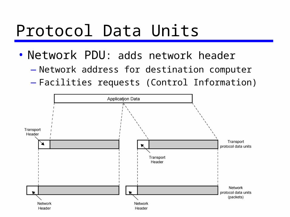
Protocol Data Units
• Network PDU: adds network header—Network address for destination computer
—Facilities requests (Control Information)
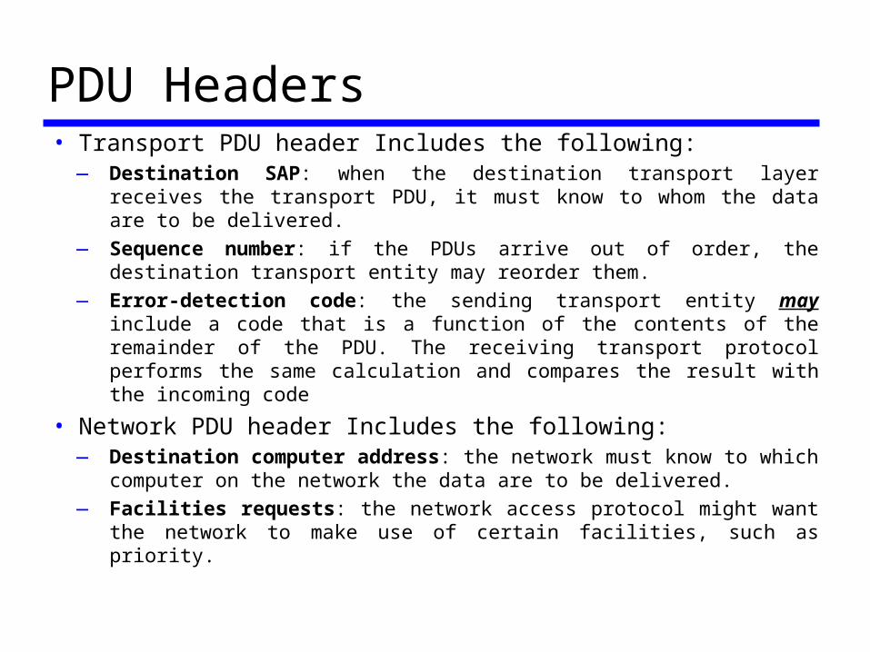
PDU Headers• Transport PDU header Includes the following:
—Destination SAP: when the destination transport layer receives the transport PDU, it must know to whom the data are to be delivered.
—Sequence number: if the PDUs arrive out of order, the destination transport entity may reorder them.
—Error-detection code: the sending transport entity may include a code that is a function of the contents of the remainder of the PDU. The receiving transport protocol performs the same calculation and compares the result with the incoming code
• Network PDU header Includes the following:—Destination computer address: the network must know to which
computer on the network the data are to be delivered.
—Facilities requests: the network access protocol might want the network to make use of certain facilities, such as priority.
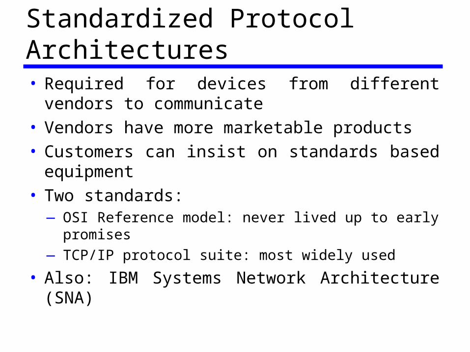
Standardized Protocol Architectures• Required for devices from different vendors to
communicate• Vendors have more marketable products• Customers can insist on standards based equipment• Two standards:
—OSI Reference model: never lived up to early promises
—TCP/IP protocol suite: most widely used
• Also: IBM Systems Network Architecture (SNA)
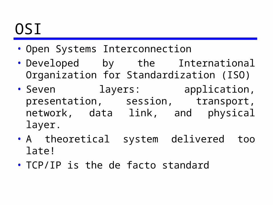
OSI• Open Systems Interconnection• Developed by the International Organization for
Standardization (ISO)• Seven layers: application, presentation, session,
transport, network, data link, and physical layer.• A theoretical system delivered too late!• TCP/IP is the de facto standard
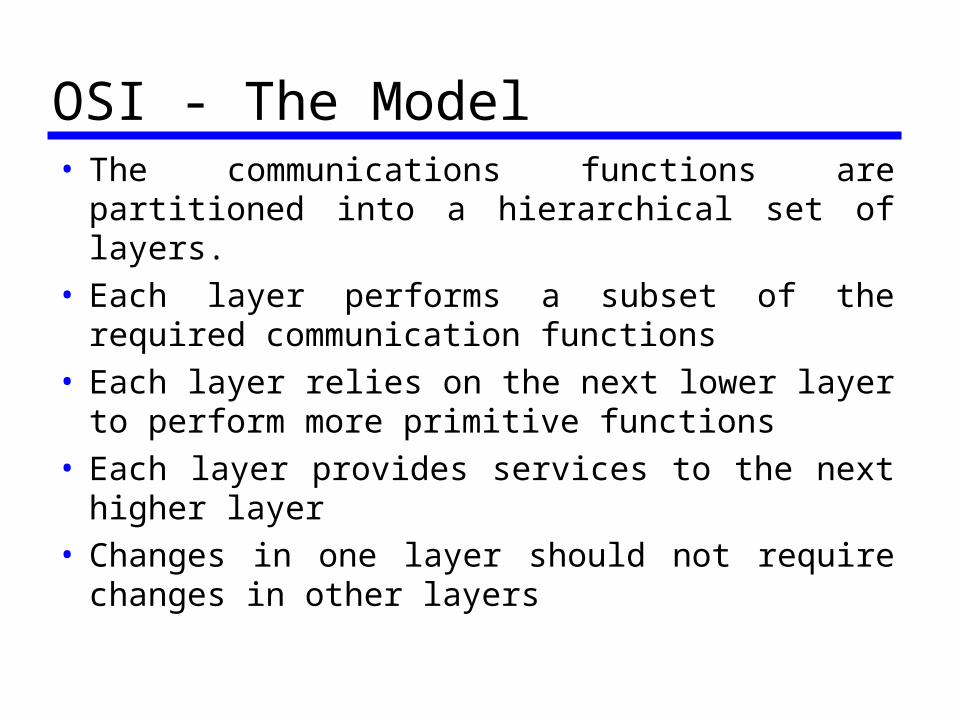
OSI - The Model• The communications functions are partitioned into a
hierarchical set of layers.• Each layer performs a subset of the required
communication functions• Each layer relies on the next lower layer to perform
more primitive functions• Each layer provides services to the next higher layer• Changes in one layer should not require changes in
other layers
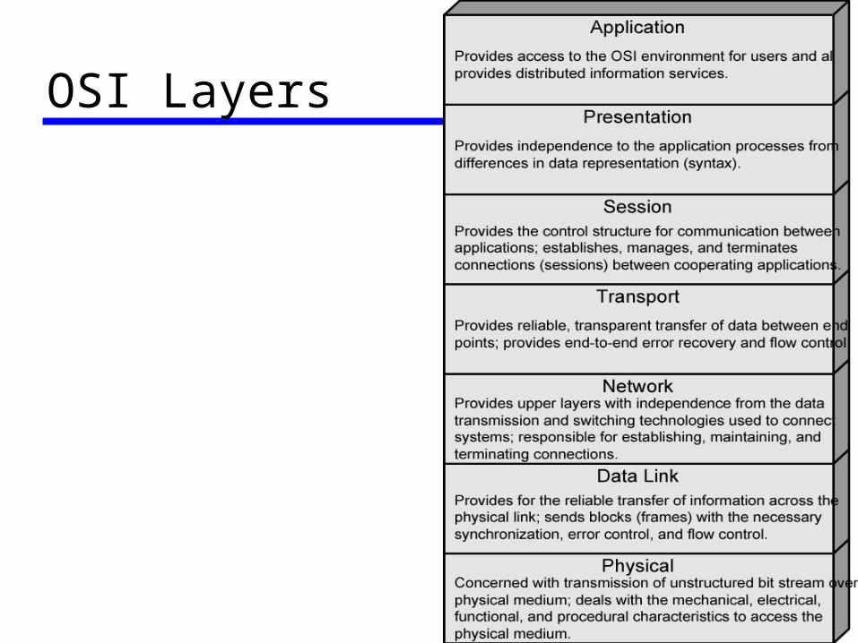
OSI Layers
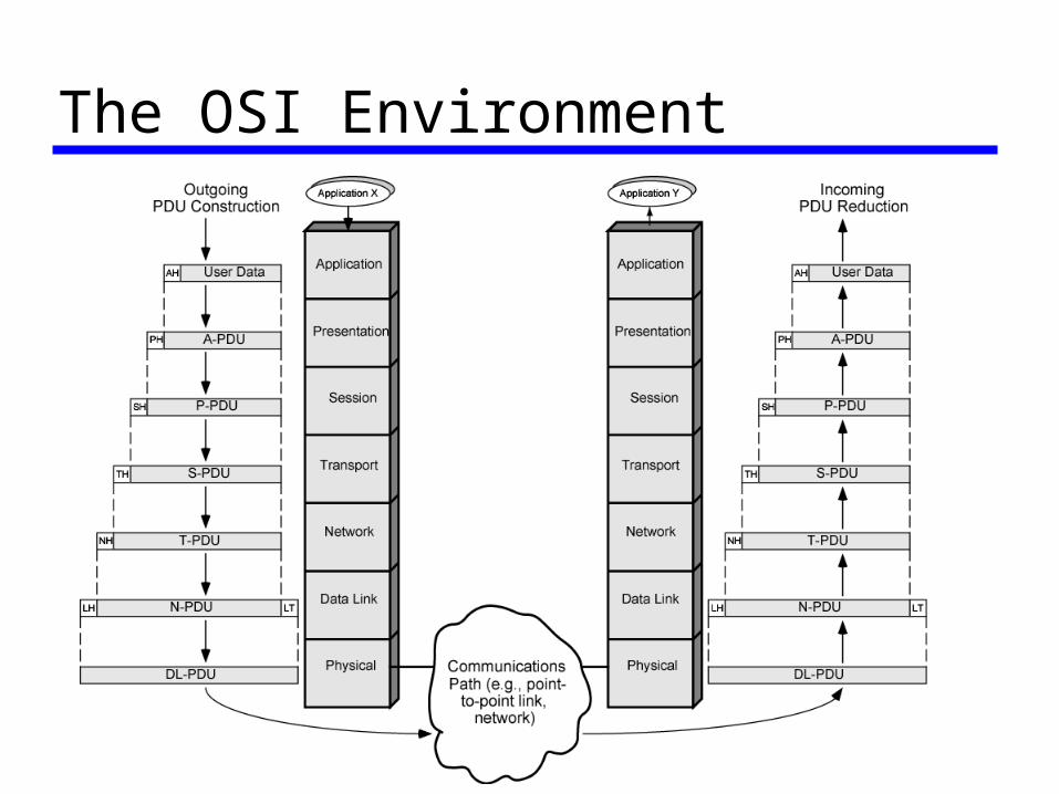
The OSI Environment
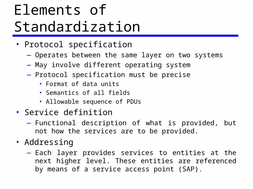
Elements of Standardization• Protocol specification
—Operates between the same layer on two systems
—May involve different operating system
—Protocol specification must be precise• Format of data units
• Semantics of all fields
• Allowable sequence of PDUs
• Service definition—Functional description of what is provided, but not how the services
are to be provided.
• Addressing—Each layer provides services to entities at the next higher level. These
entities are referenced by means of a service access point (SAP).
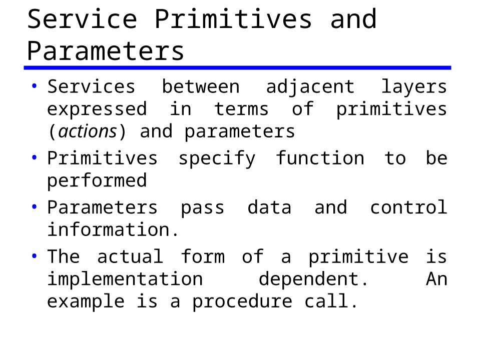
Service Primitives and Parameters• Services between adjacent layers expressed in terms
of primitives (actions) and parameters• Primitives specify function to be performed• Parameters pass data and control information.• The actual form of a primitive is implementation
dependent. An example is a procedure call.
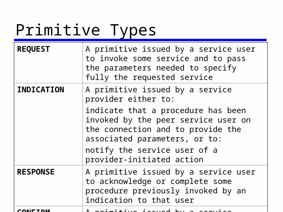
Primitive TypesREQUEST A primitive issued by a service user to invoke some
service and to pass the parameters needed to specify fully the requested service
INDICATION A primitive issued by a service provider either to:
indicate that a procedure has been invoked by the peer service user on the connection and to provide the associated parameters, or to:
notify the service user of a provider-initiated action
RESPONSE A primitive issued by a service user to acknowledge or complete some procedure previously invoked by an indication to that user
CONFIRM A primitive issued by a service provider to acknowledge or complete some procedure previously invoked by a request by the service user
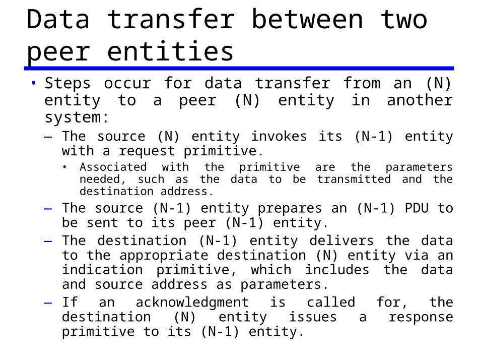
Data transfer between two peer entities• Steps occur for data transfer from an (N) entity to a
peer (N) entity in another system:—The source (N) entity invokes its (N-1) entity with a
request primitive.• Associated with the primitive are the parameters needed, such as
the data to be transmitted and the destination address.
—The source (N-1) entity prepares an (N-1) PDU to be sent to its peer (N-1) entity.
—The destination (N-1) entity delivers the data to the appropriate destination (N) entity via an indication primitive, which includes the data and source address as parameters.
—If an acknowledgment is called for, the destination (N) entity issues a response primitive to its (N-1) entity.
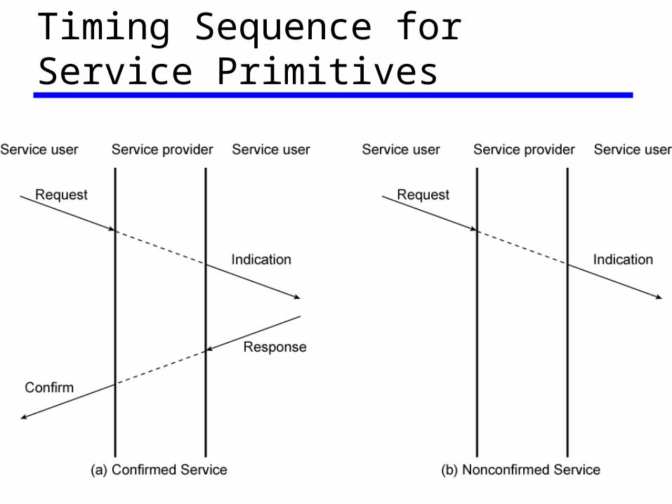
Timing Sequence for Service Primitives
OSI Layers (1)• Physical: Covers the physical interface between
devices, and rules by which bits are passed from one to another. Has the following characteristics:—Mechanical: physical properties like: pluggable
connectors and cables (called circuits)
—Electrical: bits representation (e.g. voltage levels) and transmission rate.
—Functional: specifies the function of each circuit, (control, data)
—Procedural: specifies the sequence of events by which bit streams are exchanged across the physical medium.
OSI Layers (2)• Data Link
—The data link layer attempts to make the physical link reliable.
—Provides means of activating, maintaining and deactivating a reliable link.
—Error detection and control
—Higher layers may assume error free transmission, but if the communication is between two systems that are not connected directly (different data links).
• The higher layers are not relived of an error control responsibility.
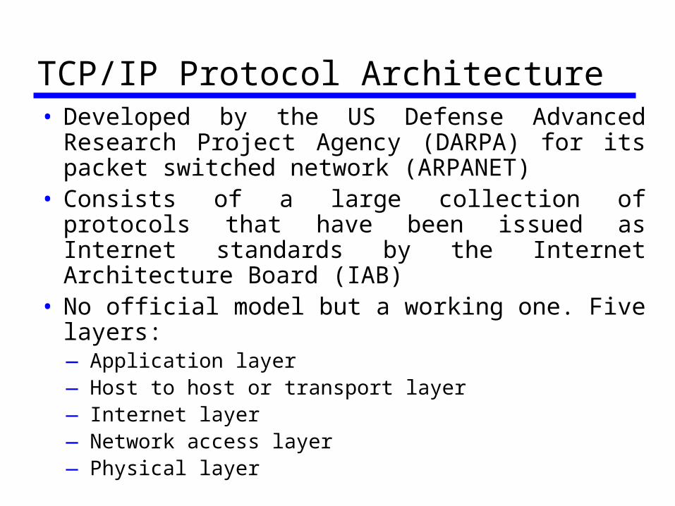
TCP/IP Protocol Architecture• Developed by the US Defense Advanced Research
Project Agency (DARPA) for its packet switched network (ARPANET)
• Consists of a large collection of protocols that have been issued as Internet standards by the Internet Architecture Board (IAB)
• No official model but a working one. Five layers:—Application layer—Host to host or transport layer—Internet layer—Network access layer—Physical layer
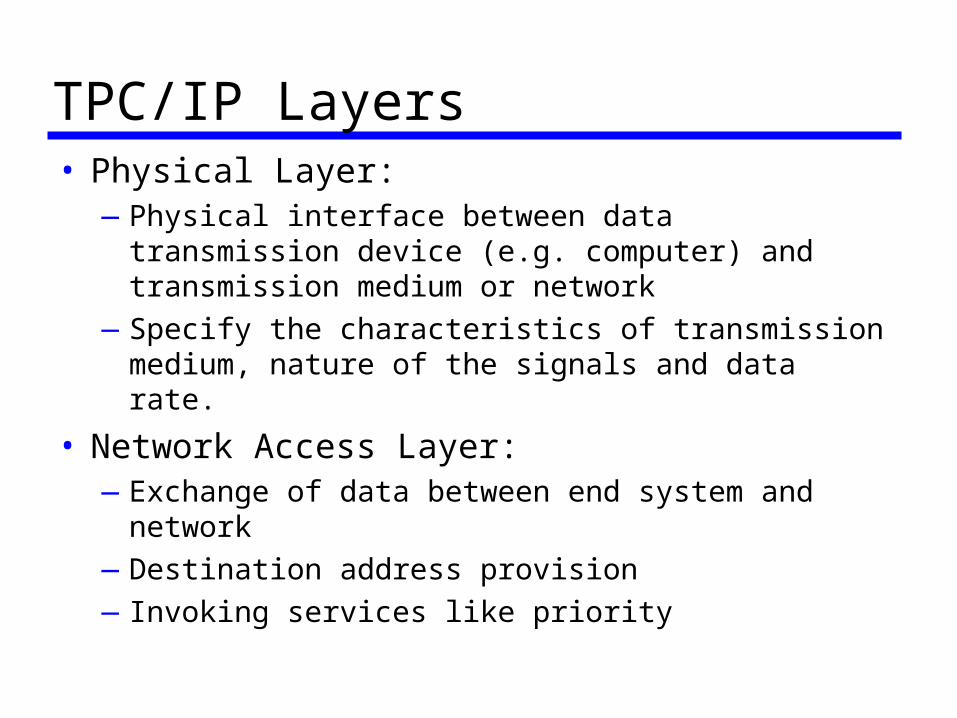
TPC/IP Layers• Physical Layer:
—Physical interface between data transmission device (e.g. computer) and transmission medium or network
—Specify the characteristics of transmission medium, nature of the signals and data rate.
• Network Access Layer:—Exchange of data between end system and network
—Destination address provision
—Invoking services like priority
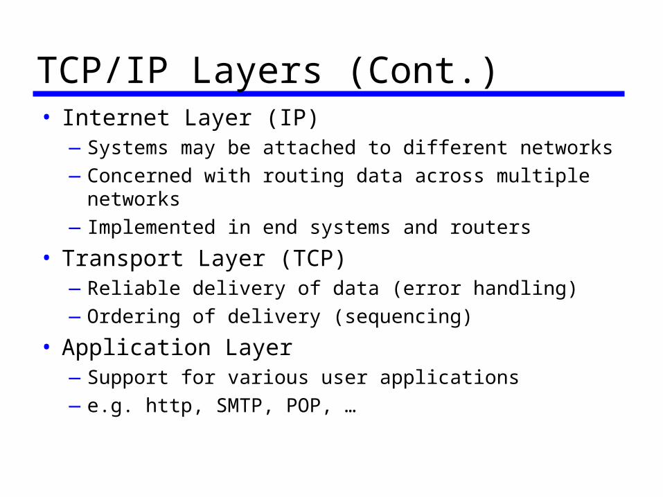
TCP/IP Layers (Cont.)• Internet Layer (IP)
—Systems may be attached to different networks
—Concerned with routing data across multiple networks
—Implemented in end systems and routers
• Transport Layer (TCP)—Reliable delivery of data (error handling)
—Ordering of delivery (sequencing)
• Application Layer—Support for various user applications
—e.g. http, SMTP, POP, …
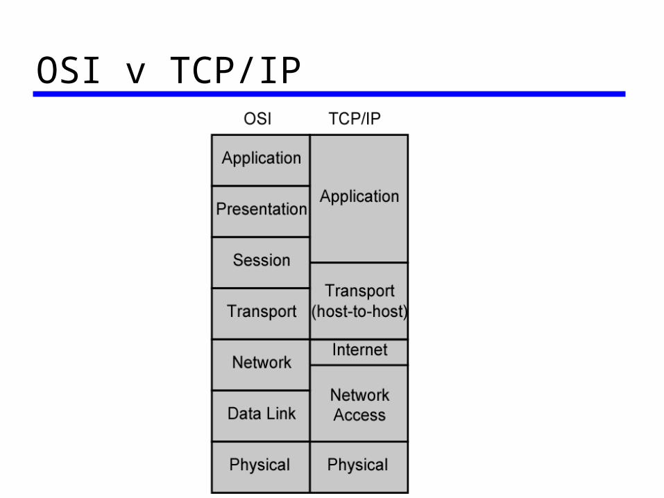
OSI v TCP/IP
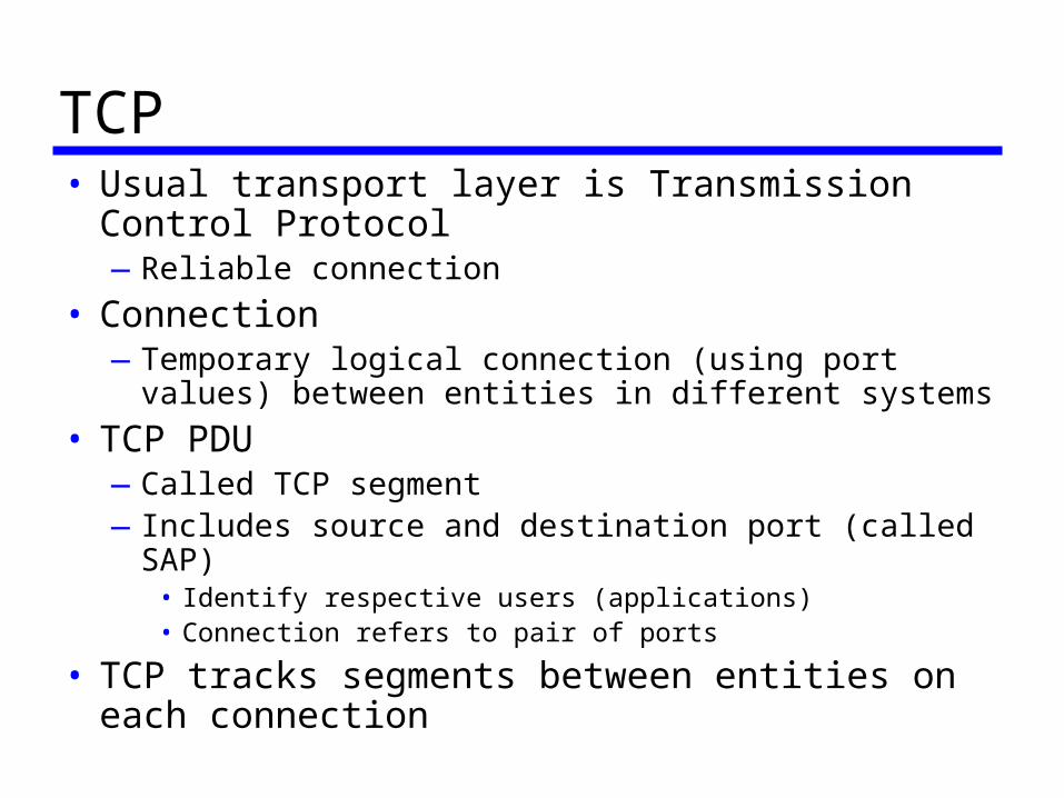
TCP• Usual transport layer is Transmission Control Protocol
—Reliable connection
• Connection—Temporary logical connection (using port values) between
entities in different systems
• TCP PDU —Called TCP segment—Includes source and destination port (called SAP)
• Identify respective users (applications)• Connection refers to pair of ports
• TCP tracks segments between entities on each connection
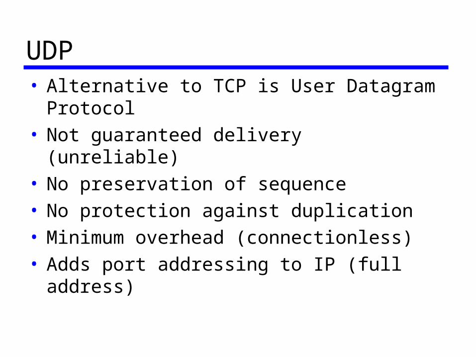
UDP• Alternative to TCP is User Datagram Protocol• Not guaranteed delivery (unreliable)• No preservation of sequence• No protection against duplication• Minimum overhead (connectionless)• Adds port addressing to IP (full address)
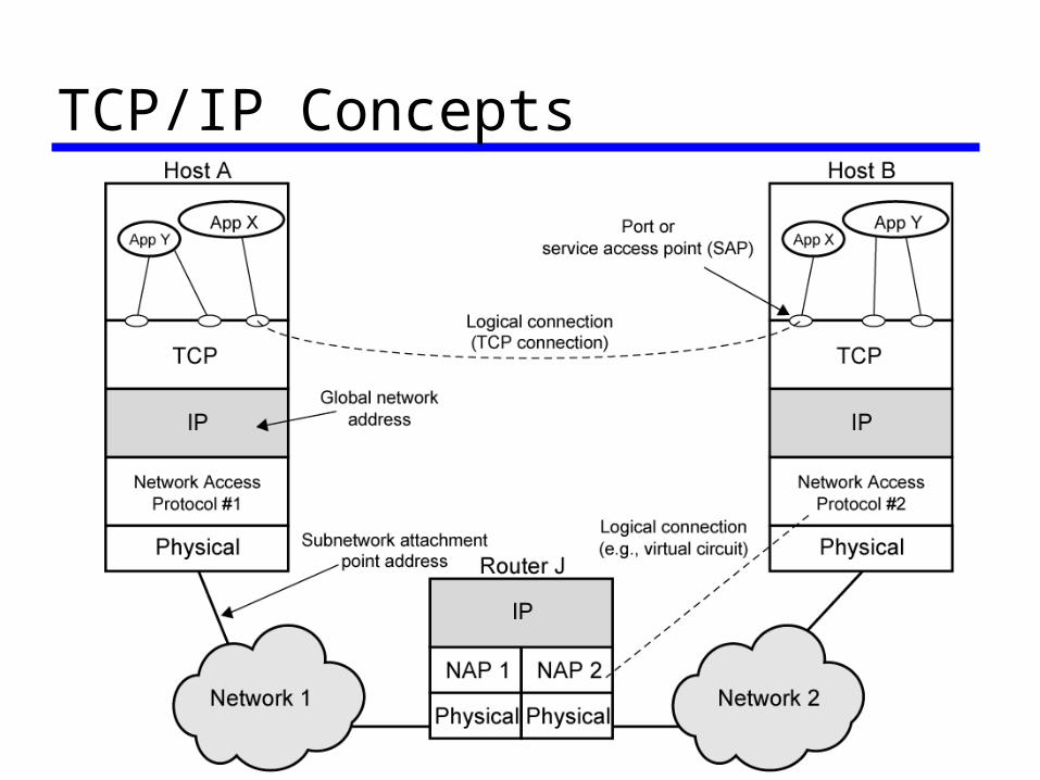
TCP/IP Concepts
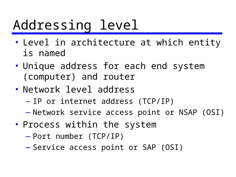
Addressing level• Level in architecture at which entity is named• Unique address for each end system (computer) and
router• Network level address
—IP or internet address (TCP/IP)
—Network service access point or NSAP (OSI)
• Process within the system—Port number (TCP/IP)
—Service access point or SAP (OSI)
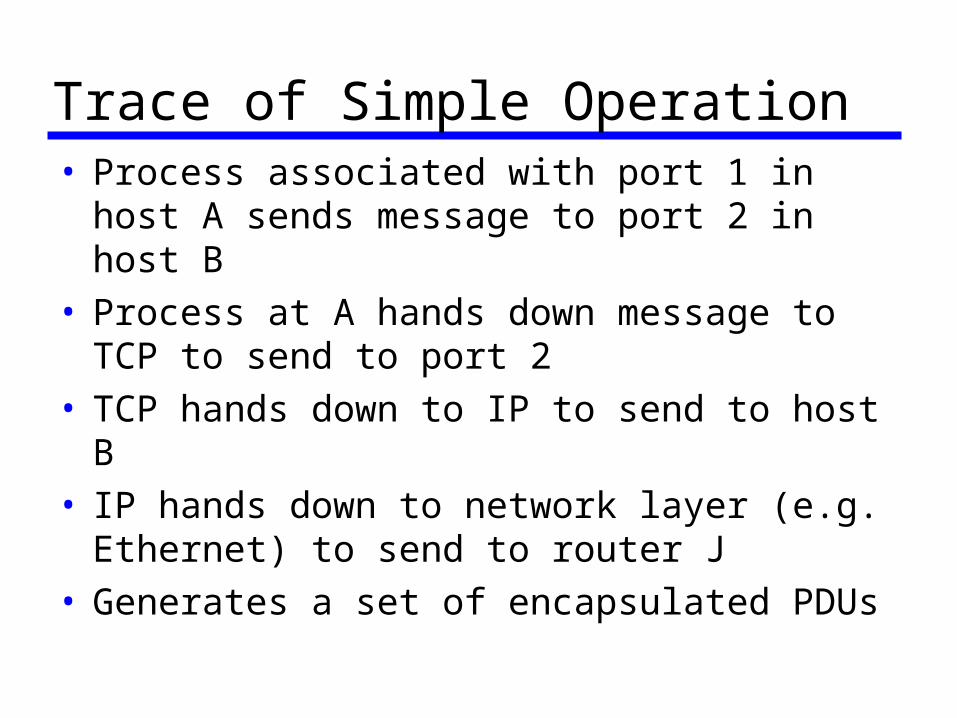
Trace of Simple Operation• Process associated with port 1 in host A sends
message to port 2 in host B• Process at A hands down message to TCP to send to
port 2• TCP hands down to IP to send to host B• IP hands down to network layer (e.g. Ethernet) to
send to router J• Generates a set of encapsulated PDUs
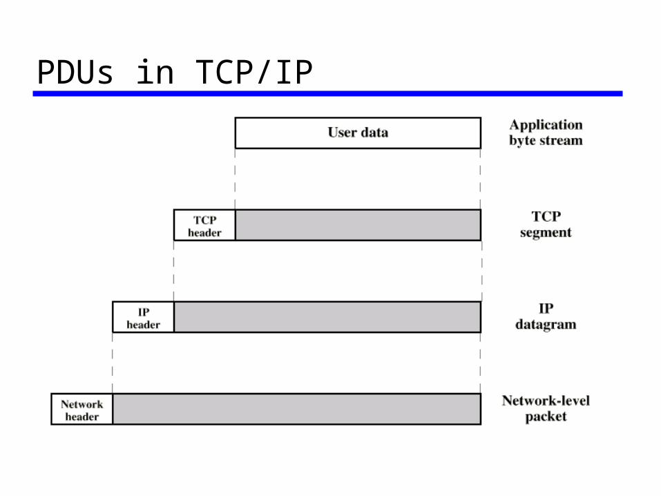
PDUs in TCP/IP
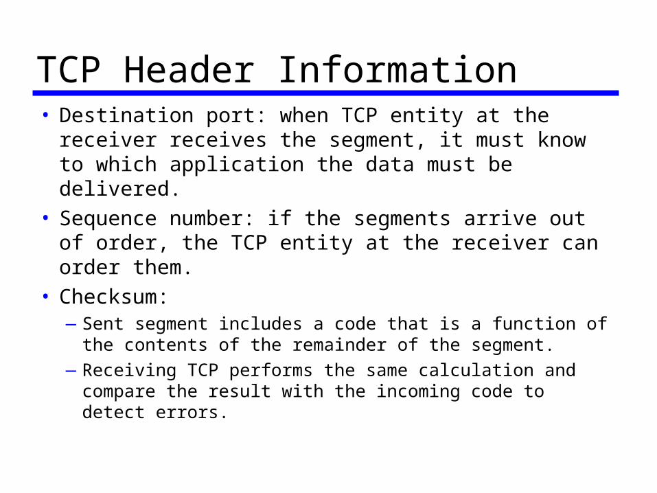
TCP Header Information• Destination port: when TCP entity at the receiver
receives the segment, it must know to which application the data must be delivered.
• Sequence number: if the segments arrive out of order, the TCP entity at the receiver can order them.
• Checksum:—Sent segment includes a code that is a function of the
contents of the remainder of the segment.
—Receiving TCP performs the same calculation and compare the result with the incoming code to detect errors.
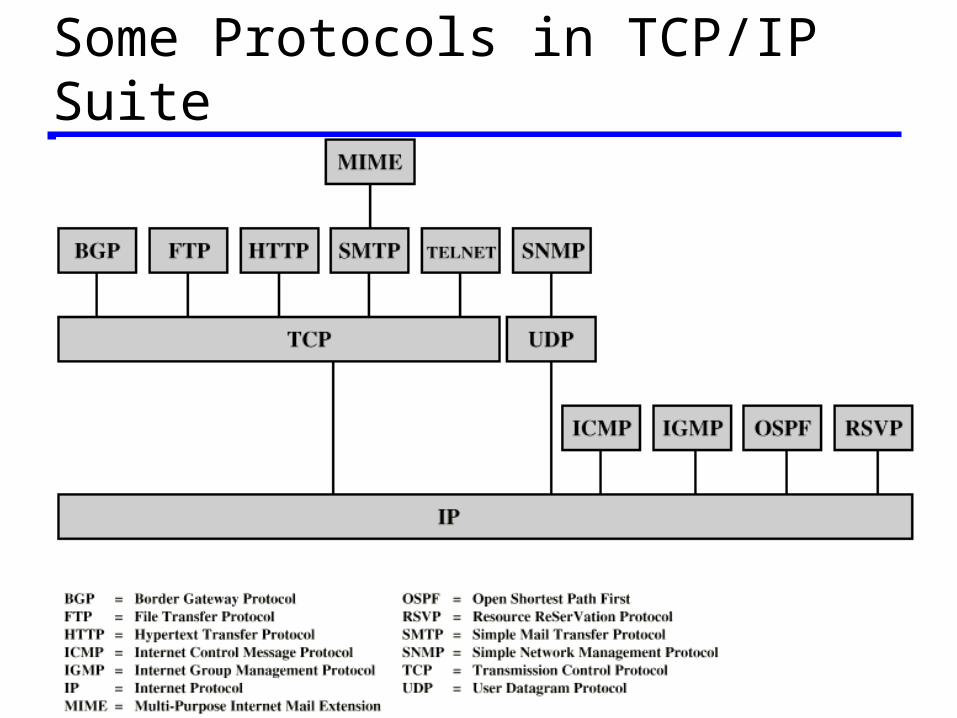
Some Protocols in TCP/IP Suite