Embed Size (px)
Citation preview

FSAR CHAPTER 5 - DESIGN OF STRUCTURES, SYSTEMS AND COMPONENTS TABLE 5.2-1 Revision 32 Page 1 of 1
PALISADES SYSTEM OF CLASSIFICATION FOR STRUCTURES/SYSTEMS/COMPONENTS
Type Source Designation Original Design, Functional(a) 1980 FSAR, Appendix A Classes 1, 2 and 3 Original Design, Seismic 1980 FSAR, Appendix A Seismic Classes 1, 2 and 3 Original Design, Mechanical (b) 1980 FSAR ASME Section III-1965, Code Classes A, B and C or ASA B31.1 (1955) Original Design, General 1984 FSAR Update CP Co Design Class Modifications Design, Seismic Regulatory Guide 1.29 Seismic Category I Service/Design for Electrical FSAR Update for Electrical Class 1E per IEEE 308 and IEEE 279 Equipment Equipment Resulting From
SEP Program, EEQ and Other Reanalysis
Maintenance/Inspection ISI Program ASME Section XI-2007 through 2008 Addenda, Code Safety Classification (Q-List) Classes 1, 2 and 3 (or Quality Groups A, B, C and D)
Regulatory Guide 1.26 P&IDs
Service/Accident 10 CFR 50.49 Environmentally Qualified (Post TMI) Regulatory Guide 1.89
Safety Classification (Q-List) Service/Accident Regulatory Guide 1.97 Category 1, 2, 3 and Types A, B, C, D and E (Post TMI) Safety Classification (Q-List) Generic - Safety Related or Important to Safety (a) Mechanical equipment including electrical equipment supporting Class 1 mechanical equipment (b) See Table 5.2-3 for more detail

FSAR CHAPTER 5 - DESIGN OF STRUCTURES, SYSTEMS AND COMPONENTS TABLE 5.2-2Revision 30Page 1 of 5
STRUCTURES CLASSIFICATION
RG 1.29INTREPRETATION
SEISMICBUILDING CLASSIFICATION DESIGN CLASS DESIGN CODE
CONTAINMENT (SHELL AND BASE Category I Class 1SLAB)
1. Concrete ACI 318-63ACI 301-66
2. Liner ASME B&PV Code,Sec III, VIII and IX, 1965
3. Personnel Air Lock, ACI 318-63Escape Air Lock, and ASME, Sec III, 1965
Equipment Hatch
4. Pipe, Electrical and HVAC ACI 318-63 Penetrations* ASME, Sec III, 1965
CONTAINMENT INTERIOR Category I Class 1 ACI 318-63STRUCTURES AISC 1963
AUXILIARY BUILDING (Excluding Category I Class 1 ACI 318-63Admin and Access Control Areas) AISC 1963
*Steam Generator Blowdown and Recirc Penetration End Plates are ASME Section III, Subsection NC, 1986 Ed.

FSAR CHAPTER 5 - DESIGN OF STRUCTURES, SYSTEMS AND COMPONENTS TABLE 5.2-2Revision 30Page 2 of 5
STRUCTURES CLASSIFICATION
RG 1.29INTREPRETATION
SEISMICBUILDING CLASSIFICATION DESIGN CLASS DESIGN CODE
(a) UBC-64 was utilized for seismic and wind loading design. In addition, International Building Code 2006 and ASCE 7-05were utilized for seismic and wind parameters for tower E-30A.
(b) Usually this applies to the basin and not the tower framing above the basin, if the basin is a backup source of water forsafety functions.
(c) The definition of Class 1E electrical equipment is provided in Subsection 8.1.1.(d) Information not located.(e) Year unknown.(f) Pultruded structure for tower E-30A was designed in accordance with Cooling Tower Institute Standard Specification 137.
1972 AUXILIARY BUILDING Category I Class 1 ACI 318-63RADWASTE ADDITION AISC 1969
1983 AUXILIARY BUILDING (d) Class 1 ACI 318-77TSC/EER/HVAC/ADDITION AISC 1978
COOLING TOWERS Category I(b) Class 3(a) (d)(f)
COOLING TOWER PUMP HOUSE Category I Class 3(a) ACI 318-71AISC 1969
DISCHARGE STRUCTURE Category I Class 3(a) UBC(e)
FEEDWATER PURITY BUILDING Noncategory I Class 3(a) UBC(e)

FSAR CHAPTER 5 - DESIGN OF STRUCTURES, SYSTEMS AND COMPONENTS TABLE 5.2-2Revision 30Page 3 of 5
STRUCTURES CLASSIFICATION
RG 1.29INTREPRETATION
SEISMICBUILDING CLASSIFICATION DESIGN CLASS DESIGN CODE
(a) UBC-64 was utilized for seismic and wind loading design. In addition, International Building Code 2006 and ASCE 7-05were utilized for seismic and wind parameters for tower E-30A.
(b) Usually this applies to the basin and not the tower framing above the basin, if the basin is a backup source of water forsafety functions.
(c) The definition of Class 1E electrical equipment is provided in Subsection 8.1.1.(d) Information not located.(e) Year unknown.(f) Pultruded structure for tower E-30A was designed in accordance with Cooling Tower Institute Standard Specification 137.
INTAKE STRUCTURE (Except as Noted) Noncategory I Class 3 UBC(e)
1. Portion Above Elevation 590 Category I Class 1 ACI 318-63 Housing Service Water Pumps, AISC 1963 Fire Pumps/Drivers and Electrical Support
2. Triangular Portion Below Category I Class 1 ACI 318-63 Elevation 590 Adjacent to the AISC 1963 Intersection of Column Rows Y and 5
SERVICE BUILDING Noncategory I Class 3(a) UBC(e)
SUPPORTS FOR CLASS 1 MECHANI- Category I Class 1 AISC 1969CAL EQUIPMENT AND CLASS 1EELECTRICAL EQUIPMENT(c)

FSAR CHAPTER 5 - DESIGN OF STRUCTURES, SYSTEMS AND COMPONENTS TABLE 5.2-2Revision 30Page 4 of 5
STRUCTURES CLASSIFICATION
RG 1.29INTREPRETATION
SEISMICBUILDING CLASSIFICATION DESIGN CLASS DESIGN CODE
(a) UBC-64 was utilized for seismic and wind loading design. In addition, International Building Code 2006 and ASCE 7-05were utilized for seismic and wind parameters for tower E-30A.
(b) Usually this applies to the basin and not the tower framing above the basin, if the basin is a backup source of water forsafety functions.
(c) The definition of Class 1E electrical equipment is provided in Subsection 8.1.1.(d) Information not located.(e) Year unknown.(f) Pultruded structure for tower E-30A was designed in accordance with Cooling Tower Institute Standard Specification 137.
TURBINE BUILDING (Except as Noted) Noncategory I Class 3(a) ACI 318-63AISC 1963
1. Auxiliary Feedwater Pump Category I Class 1 ACI 318-63 Room AISC 1963
2. Electrical Penetration Category I Class 1 ACI 318-63 Enclosure
CONDENSATE STORAGE TANK Category I Class 1 ACI 318-63FOUNDATION
PRIMARY SYSTEM MAKEUP TANK Category I Class 1 ACI 318-63FOUNDATION (T-90)
SIRW TANK FOUNDATION Category I Class 1 ACI 318-63

FSAR CHAPTER 5 - DESIGN OF STRUCTURES, SYSTEMS AND COMPONENTS TABLE 5.2-2Revision 30Page 5 of 5
STRUCTURES CLASSIFICATION
RG 1.29INTREPRETATION
SEISMICBUILDING CLASSIFICATION DESIGN CLASS DESIGN CODE
(a) UBC-64 was utilized for seismic and wind loading design. In addition, International Building Code 2006 and ASCE 7-05were utilized for seismic and wind parameters for tower E-30A.
(b) Usually this applies to the basin and not the tower framing above the basin, if the basin is a backup source of water forsafety functions.
(c) The definition of Class 1E electrical equipment is provided in Subsection 8.1.1.(d) Information not located.(e) Year unknown.(f) Pultruded structure for tower E-30A was designed in accordance with Cooling Tower Institute Standard Specification 137.
UTILITY WATER TANK FOUNDATION Category I Class 1 ACI 318-63(T-91)

FSAR CHAPTER 5 - DESIGN OF STRUCTURES, SYSTEMS AND COMPONENTS TABLE 5.2-3 Revision 32 Page 1 of 23
MECHANICAL SYSTEM/COMPONENT CLASSIFICATION
Seismic Class Class per per RG 1.29 CP Co Design RG 1.26
System/Component Interpretation(a) Class(b) Interpretation(c) Standards Used in Plant Design
(a) Seismic category as identified in the Franklin Research Center Technical Evaluation Report TER-C5257-428 Pursuant to SEP Topic III-1 and other related materials. This
column is intended for informational purposes only and is not intended to impose design requirements. (b) Equipment classification was originally identified in the Palisades 1980 FSAR, APPENDIX A, and TER-C5257-428 and as modified by CPCo. (c) Class pursuant to the ASME B&PV Code, Section III, Division 1, Subsection NB, 1977 edition, 1978 addenda, as determined by TER-C5257-428, pursuant to
SEP Topic III-1 and modified by CP Co. (d) Current design requirements for non-PCS piping are reconciled to ANSI B 31.1, 1973 Ed with 1973 Summer Addenda. See Sections 5.10.1 and 5.10.2. (e) Nitrogen Gas Backup Stations 1 and 2 reflect a seismic design from an earlier revision of the FSAR not consistent with the requirements in Section 5.2.2 of the current
revision of the FSAR. The design of Stations 1 and 2 (FC-675) used 0.5 x OBE for seismic design. (f) Seismic Class I Supported from Receivers to Operators on Engineered Safe-guards Systems. (g) CPCo Design Class and ASME / Reg Guide 1.26 Class for the Chemical and Volume Control System were revised per EAR-1999-0081 to reflect that the system is no
longer credited in the Chapter 14 safety analyses.
REACTOR COOLANT SYSTEM Reactor Vessel Category I Class 1 ASME III ASME III (1965) - Class A
Class 1 Reactor Vessel Supports Category I Class 1 ASME III ASME III (1965) - Class A
Class 1 Steam Generators - Tube Side Category I Class 1 ASME III ASME III (1977) - Section NB and Primary Head Class 1 Steam Generators - Secondary Side Category I Class 1 ASME III ASME III (1977) - Section NC
Class 2 Steam Generator Supports Category I Class 1 ASME III ASME III (1965) - Class A
Class 1 Pressurizer Category I Class 1 ASME III ASME III (1965) - Class A
Class 1 ASA B31.1 (1955) Primary Coolant Pumps (PCP) Category I Class 1 ASME III ASME III (1965) - Class A
Class 1 Standards of Hydraulic Institute (SHI) ASA B31.1 (1955) ASA B16.5 (1961)

FSAR CHAPTER 5 - DESIGN OF STRUCTURES, SYSTEMS AND COMPONENTS TABLE 5.2-3 Revision 32 Page 2 of 23
MECHANICAL SYSTEM/COMPONENT CLASSIFICATION
Seismic Class Class per per RG 1.29 CP Co Design RG 1.26
System/Component Interpretation(a) Class(b) Interpretation(c) Standards Used in Plant Design
(a) Seismic category as identified in the Franklin Research Center Technical Evaluation Report TER-C5257-428 Pursuant to SEP Topic III-1 and other related materials. This
column is intended for informational purposes only and is not intended to impose design requirements. (b) Equipment classification was originally identified in the Palisades 1980 FSAR, APPENDIX A, and TER-C5257-428 and as modified by CPCo. (c) Class pursuant to the ASME B&PV Code, Section III, Division 1, Subsection NB, 1977 edition, 1978 addenda, as determined by TER-C5257-428, pursuant to
SEP Topic III-1 and modified by CP Co. (d) Current design requirements for non-PCS piping are reconciled to ANSI B 31.1, 1973 Ed with 1973 Summer Addenda. See Sections 5.10.1 and 5.10.2. (e) Nitrogen Gas Backup Stations 1 and 2 reflect a seismic design from an earlier revision of the FSAR not consistent with the requirements in Section 5.2.2 of the current
revision of the FSAR. The design of Stations 1 and 2 (FC-675) used 0.5 x OBE for seismic design. (f) Seismic Class I Supported from Receivers to Operators on Engineered Safe-guards Systems. (g) CPCo Design Class and ASME / Reg Guide 1.26 Class for the Chemical and Volume Control System were revised per EAR-1999-0081 to reflect that the system is no
longer credited in the Chapter 14 safety analyses.
Primary Coolant Pump Internals Category I Class 1 ASME III -
Class 1 Piping - PCS Hot and Cold Legs Category I Class 1 ASME III ASA B31.1 (1955)
Class 1 Interconnecting Piping of Systems That Category I Class 1 ASME III ASA B31.1 (1955) Form Part of Primary Coolant Pressure Class 1 Boundary (PCPB) Pressurizer Surge and Spray Category I Class 1 ASME III ASA B31.1 (1955)
Class 1 Piping 3/4 Inch and Smaller Within PCPB Category I Class 1 ASME III ASA B31.1 (1955)
Class 1 Pressurizer Relief Discharge Piping - Category I Class 1 ASME III ASA B31.1 (1955) Upstream of Safety Valves Class 1
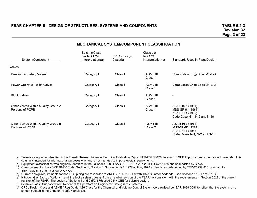
FSAR CHAPTER 5 - DESIGN OF STRUCTURES, SYSTEMS AND COMPONENTS TABLE 5.2-3 Revision 32 Page 3 of 23
MECHANICAL SYSTEM/COMPONENT CLASSIFICATION
Seismic Class Class per per RG 1.29 CP Co Design RG 1.26
System/Component Interpretation(a) Class(b) Interpretation(c) Standards Used in Plant Design
(a) Seismic category as identified in the Franklin Research Center Technical Evaluation Report TER-C5257-428 Pursuant to SEP Topic III-1 and other related materials. This
column is intended for informational purposes only and is not intended to impose design requirements. (b) Equipment classification was originally identified in the Palisades 1980 FSAR, APPENDIX A, and TER-C5257-428 and as modified by CPCo. (c) Class pursuant to the ASME B&PV Code, Section III, Division 1, Subsection NB, 1977 edition, 1978 addenda, as determined by TER-C5257-428, pursuant to
SEP Topic III-1 and modified by CP Co. (d) Current design requirements for non-PCS piping are reconciled to ANSI B 31.1, 1973 Ed with 1973 Summer Addenda. See Sections 5.10.1 and 5.10.2. (e) Nitrogen Gas Backup Stations 1 and 2 reflect a seismic design from an earlier revision of the FSAR not consistent with the requirements in Section 5.2.2 of the current
revision of the FSAR. The design of Stations 1 and 2 (FC-675) used 0.5 x OBE for seismic design. (f) Seismic Class I Supported from Receivers to Operators on Engineered Safe-guards Systems. (g) CPCo Design Class and ASME / Reg Guide 1.26 Class for the Chemical and Volume Control System were revised per EAR-1999-0081 to reflect that the system is no
longer credited in the Chapter 14 safety analyses.
Valves Pressurizer Safety Valves Category I Class 1 ASME III Combustion Engg Spec M1-L-B
Class 1 Power-Operated Relief Valves Category I Class 1 ASME III Combustion Engg Spec M1-L-B
Class 1 Block Valves Category I Class 1 ASME III -
Class 1 Other Valves Within Quality Group A Category I Class 1 ASME III ASA B16.5 (1961) Portions of PCPB Class 1 MSS-SP-61 (1961)
ASA B31.1 (1955) Code Case N-1, N-2 and N-10
Other Valves Within Quality Group B Category I Class 1 ASME III ASA B16.5 (1961) Portions of PCPB Class 2 MSS-SP-61 (1961)
ASA B31.1 (1955) Code Cases N-1, N-2 and N-10

FSAR CHAPTER 5 - DESIGN OF STRUCTURES, SYSTEMS AND COMPONENTS TABLE 5.2-3 Revision 32 Page 4 of 23
MECHANICAL SYSTEM/COMPONENT CLASSIFICATION
Seismic Class Class per per RG 1.29 CP Co Design RG 1.26
System/Component Interpretation(a) Class(b) Interpretation(c) Standards Used in Plant Design
(a) Seismic category as identified in the Franklin Research Center Technical Evaluation Report TER-C5257-428 Pursuant to SEP Topic III-1 and other related materials. This
column is intended for informational purposes only and is not intended to impose design requirements. (b) Equipment classification was originally identified in the Palisades 1980 FSAR, APPENDIX A, and TER-C5257-428 and as modified by CPCo. (c) Class pursuant to the ASME B&PV Code, Section III, Division 1, Subsection NB, 1977 edition, 1978 addenda, as determined by TER-C5257-428, pursuant to
SEP Topic III-1 and modified by CP Co. (d) Current design requirements for non-PCS piping are reconciled to ANSI B 31.1, 1973 Ed with 1973 Summer Addenda. See Sections 5.10.1 and 5.10.2. (e) Nitrogen Gas Backup Stations 1 and 2 reflect a seismic design from an earlier revision of the FSAR not consistent with the requirements in Section 5.2.2 of the current
revision of the FSAR. The design of Stations 1 and 2 (FC-675) used 0.5 x OBE for seismic design. (f) Seismic Class I Supported from Receivers to Operators on Engineered Safe-guards Systems. (g) CPCo Design Class and ASME / Reg Guide 1.26 Class for the Chemical and Volume Control System were revised per EAR-1999-0081 to reflect that the system is no
longer credited in the Chapter 14 safety analyses.
REACTOR PRIMARY SHIELD COOLING SYSTEM Cooling Coils Noncategory I Class 3 Nonclass ASA B31.1 Cooling Pumps Noncategory I Class 3 Nonclass HSI, NEMA, ASA and ASTM Heat Exchanger Noncategory I Class 3 Nonclass ASME III, Class C, ASME VIII, Para UW-2,
TEMA, Class C Surge Tank Noncategory I Class 3 Nonclass ASME III, Class C and ASME VIII, Para UW-2 Piping and Valves Noncategory I Class 3 Nonclass ASA B31.1, ASA B16.5 SAFETY INJECTION SYSTEM Refueling Water Storage Tank Category I - ASME III ASA B96.1 (1967)
Class 2 ASME III (1977 and 78) Evaluated Safety Injection Tanks Category I - ASME III ASME III (1965) - Class C
Class 2 Interconnecting Piping and Valves Category I - ASME III ASA B31.1 (1955) Required To Perform Safety Injection Class 2 ASA B16.5 (1961) Function Code Cases N-1 Through N-13

FSAR CHAPTER 5 - DESIGN OF STRUCTURES, SYSTEMS AND COMPONENTS TABLE 5.2-3 Revision 32 Page 5 of 23
MECHANICAL SYSTEM/COMPONENT CLASSIFICATION
Seismic Class Class per per RG 1.29 CP Co Design RG 1.26
System/Component Interpretation(a) Class(b) Interpretation(c) Standards Used in Plant Design
(a) Seismic category as identified in the Franklin Research Center Technical Evaluation Report TER-C5257-428 Pursuant to SEP Topic III-1 and other related materials. This
column is intended for informational purposes only and is not intended to impose design requirements. (b) Equipment classification was originally identified in the Palisades 1980 FSAR, APPENDIX A, and TER-C5257-428 and as modified by CPCo. (c) Class pursuant to the ASME B&PV Code, Section III, Division 1, Subsection NB, 1977 edition, 1978 addenda, as determined by TER-C5257-428, pursuant to
SEP Topic III-1 and modified by CP Co. (d) Current design requirements for non-PCS piping are reconciled to ANSI B 31.1, 1973 Ed with 1973 Summer Addenda. See Sections 5.10.1 and 5.10.2. (e) Nitrogen Gas Backup Stations 1 and 2 reflect a seismic design from an earlier revision of the FSAR not consistent with the requirements in Section 5.2.2 of the current
revision of the FSAR. The design of Stations 1 and 2 (FC-675) used 0.5 x OBE for seismic design. (f) Seismic Class I Supported from Receivers to Operators on Engineered Safe-guards Systems. (g) CPCo Design Class and ASME / Reg Guide 1.26 Class for the Chemical and Volume Control System were revised per EAR-1999-0081 to reflect that the system is no
longer credited in the Chapter 14 safety analyses.
Interconnecting Piping and Valves Category I Class 1 ASME III ASA B31.1 (1955) Required to Perform Recirculation Class 2 ASA B16.5 (1961) Function Code Cases N-1 Through N-13 Long-Term Cooling Modification Category I Class 1 ASME III ASME/ANSI B31.1-1980
Classes 1 & 2 ANSI N18.2-1973 High-Pressure Safety Injection Pump Category I Class 1 ASME III ASME VIII (1965)
Class 2 ASA B16.5 (1961) SHI
Low-Pressure Safety Injection Pumps Category I Class 1 ASME III ASME VIII (1965)
Class 2 ASA B16.5 (1961) SHI

FSAR CHAPTER 5 - DESIGN OF STRUCTURES, SYSTEMS AND COMPONENTS TABLE 5.2-3 Revision 32 Page 6 of 23
MECHANICAL SYSTEM/COMPONENT CLASSIFICATION
Seismic Class Class per per RG 1.29 CP Co Design RG 1.26
System/Component Interpretation(a) Class(b) Interpretation(c) Standards Used in Plant Design
(a) Seismic category as identified in the Franklin Research Center Technical Evaluation Report TER-C5257-428 Pursuant to SEP Topic III-1 and other related materials. This
column is intended for informational purposes only and is not intended to impose design requirements. (b) Equipment classification was originally identified in the Palisades 1980 FSAR, APPENDIX A, and TER-C5257-428 and as modified by CPCo. (c) Class pursuant to the ASME B&PV Code, Section III, Division 1, Subsection NB, 1977 edition, 1978 addenda, as determined by TER-C5257-428, pursuant to
SEP Topic III-1 and modified by CP Co. (d) Current design requirements for non-PCS piping are reconciled to ANSI B 31.1, 1973 Ed with 1973 Summer Addenda. See Sections 5.10.1 and 5.10.2. (e) Nitrogen Gas Backup Stations 1 and 2 reflect a seismic design from an earlier revision of the FSAR not consistent with the requirements in Section 5.2.2 of the current
revision of the FSAR. The design of Stations 1 and 2 (FC-675) used 0.5 x OBE for seismic design. (f) Seismic Class I Supported from Receivers to Operators on Engineered Safe-guards Systems. (g) CPCo Design Class and ASME / Reg Guide 1.26 Class for the Chemical and Volume Control System were revised per EAR-1999-0081 to reflect that the system is no
longer credited in the Chapter 14 safety analyses.
CONTAINMENT SPRAY SYSTEM Pumps Category I Class 1 ASME III SHI, ASA B31.1, ASA B16.5 (1967 Inclusive)
Class 2 Interconnecting Piping and Valves Category I Class 1 ASME III ASA B31.1 (1955) Required To Perform Spray Function Class 2 ASA B16.5 (1961)
Code Cases N-1 Through N-13 Interconnecting Piping and Valves Category I Class 1 ASME III ASA B31.1 (1955) Required To Perform Test Function Class 2 ASA B16.5 (1961)
Code Cases N-1 Through N-13 CHEMICAL AND VOLUME CONTROL SYSTEM Regenerative Heat Exchange Category I Class 1 ASME III ASME III (1965) - Class C
Class 1 ASME III, Ap IX (1965 W67) Letdown Heat Exchanger - Tube Side Category I Class 1 ASME III ASME III (1965) - Class C
Class 3 ASME III, Ap IX (1965 W67) Letdown Heat Exchanger - Shell Side(g) Category I Class 3 Nonclass ASME III (1965) - Class C Purification Filter(g) Category I Class 3 Nonclass ASME III (1965) - Class C

FSAR CHAPTER 5 - DESIGN OF STRUCTURES, SYSTEMS AND COMPONENTS TABLE 5.2-3 Revision 32 Page 7 of 23
MECHANICAL SYSTEM/COMPONENT CLASSIFICATION
Seismic Class Class per per RG 1.29 CP Co Design RG 1.26
System/Component Interpretation(a) Class(b) Interpretation(c) Standards Used in Plant Design
(a) Seismic category as identified in the Franklin Research Center Technical Evaluation Report TER-C5257-428 Pursuant to SEP Topic III-1 and other related materials. This
column is intended for informational purposes only and is not intended to impose design requirements. (b) Equipment classification was originally identified in the Palisades 1980 FSAR, APPENDIX A, and TER-C5257-428 and as modified by CPCo. (c) Class pursuant to the ASME B&PV Code, Section III, Division 1, Subsection NB, 1977 edition, 1978 addenda, as determined by TER-C5257-428, pursuant to
SEP Topic III-1 and modified by CP Co. (d) Current design requirements for non-PCS piping are reconciled to ANSI B 31.1, 1973 Ed with 1973 Summer Addenda. See Sections 5.10.1 and 5.10.2. (e) Nitrogen Gas Backup Stations 1 and 2 reflect a seismic design from an earlier revision of the FSAR not consistent with the requirements in Section 5.2.2 of the current
revision of the FSAR. The design of Stations 1 and 2 (FC-675) used 0.5 x OBE for seismic design. (f) Seismic Class I Supported from Receivers to Operators on Engineered Safe-guards Systems. (g) CPCo Design Class and ASME / Reg Guide 1.26 Class for the Chemical and Volume Control System were revised per EAR-1999-0081 to reflect that the system is no
longer credited in the Chapter 14 safety analyses.
Volume Control Tank (VCT)(g) Category I Class 3 Nonclass ASME III (1965) - Class C Charging Pumps(g) Category I Class 3 Nonclass ASME VIII (1965)
ASA B16.5 (1961) Letdown Orifices(g) Category I Class 1 ASME III ASA B31.1 (1955)
Class 3 Interconnecting Piping and Valves Category I Class 3 ASA B31.1 (1955) Required To Perform Letdown, Charging, Nonclass ASA B16.5 (1961) and Supply of makeup water to Safety Injection Code Cases N-1 Through N-13 and Refueling Water Tanks' Functions(g) Concentrated Boric Acid Tanks (T-53)(g) Category I Class 3 Nonclass ASME III (1965) - Class C
Boric Acid Filter (F-9) Category I Class 3 Nonclass ASME III (1965) - Class C
Concentrated Boric Acid Transfer Pumps(g) Category I Class 3 Nonclass SHI
ASA B16.5 (1961) Boric Acid Blender(g) Category I Class 3 Nonclass Combustion Engg Spec M1-H
Bechtel Spec M-52

FSAR CHAPTER 5 - DESIGN OF STRUCTURES, SYSTEMS AND COMPONENTS TABLE 5.2-3 Revision 32 Page 8 of 23
MECHANICAL SYSTEM/COMPONENT CLASSIFICATION
Seismic Class Class per per RG 1.29 CP Co Design RG 1.26
System/Component Interpretation(a) Class(b) Interpretation(c) Standards Used in Plant Design
(a) Seismic category as identified in the Franklin Research Center Technical Evaluation Report TER-C5257-428 Pursuant to SEP Topic III-1 and other related materials. This
column is intended for informational purposes only and is not intended to impose design requirements. (b) Equipment classification was originally identified in the Palisades 1980 FSAR, APPENDIX A, and TER-C5257-428 and as modified by CPCo. (c) Class pursuant to the ASME B&PV Code, Section III, Division 1, Subsection NB, 1977 edition, 1978 addenda, as determined by TER-C5257-428, pursuant to
SEP Topic III-1 and modified by CP Co. (d) Current design requirements for non-PCS piping are reconciled to ANSI B 31.1, 1973 Ed with 1973 Summer Addenda. See Sections 5.10.1 and 5.10.2. (e) Nitrogen Gas Backup Stations 1 and 2 reflect a seismic design from an earlier revision of the FSAR not consistent with the requirements in Section 5.2.2 of the current
revision of the FSAR. The design of Stations 1 and 2 (FC-675) used 0.5 x OBE for seismic design. (f) Seismic Class I Supported from Receivers to Operators on Engineered Safe-guards Systems. (g) CPCo Design Class and ASME / Reg Guide 1.26 Class for the Chemical and Volume Control System were revised per EAR-1999-0081 to reflect that the system is no
longer credited in the Chapter 14 safety analyses.
Interconnecting Piping and Valves Category I Class 3 Nonclass ASA B31.1 (1955) Required for Boric Acid Storage and ASA B16.5 (1961) Supply Function(g) Code Cases N-1 Through N-13 Boric Acid Supply Lines(g) Category I Class 3 Nonclass ASA B31.1 (1955)
ASA B16.5 (1961) Code Cases N-1 Through n-13
Purification Demineralizer(g) Category I Class 3 Nonclass ASME III (1965) Deborating Demineralizer(g) Category I Class 3 Nonclass ASME III (1965) Interconnecting Piping and Valves Category I Class 3 Nonclass ASA B31.1 (1955) Required to Perform Demineralizer ASA B16.5 (1961) Function(g) Code Cases N-1 Through N-13 Auxiliary Pressurizer Spray Piping Category I Class 1 ASME III ASA B31.1 (1955) and Valves Class 1 ASA B16.5 (1965)
Code Cases N-1 Through N-13

FSAR CHAPTER 5 - DESIGN OF STRUCTURES, SYSTEMS AND COMPONENTS TABLE 5.2-3 Revision 32 Page 9 of 23
MECHANICAL SYSTEM/COMPONENT CLASSIFICATION
Seismic Class Class per per RG 1.29 CP Co Design RG 1.26
System/Component Interpretation(a) Class(b) Interpretation(c) Standards Used in Plant Design
(a) Seismic category as identified in the Franklin Research Center Technical Evaluation Report TER-C5257-428 Pursuant to SEP Topic III-1 and other related materials. This
column is intended for informational purposes only and is not intended to impose design requirements. (b) Equipment classification was originally identified in the Palisades 1980 FSAR, APPENDIX A, and TER-C5257-428 and as modified by CPCo. (c) Class pursuant to the ASME B&PV Code, Section III, Division 1, Subsection NB, 1977 edition, 1978 addenda, as determined by TER-C5257-428, pursuant to
SEP Topic III-1 and modified by CP Co. (d) Current design requirements for non-PCS piping are reconciled to ANSI B 31.1, 1973 Ed with 1973 Summer Addenda. See Sections 5.10.1 and 5.10.2. (e) Nitrogen Gas Backup Stations 1 and 2 reflect a seismic design from an earlier revision of the FSAR not consistent with the requirements in Section 5.2.2 of the current
revision of the FSAR. The design of Stations 1 and 2 (FC-675) used 0.5 x OBE for seismic design. (f) Seismic Class I Supported from Receivers to Operators on Engineered Safe-guards Systems. (g) CPCo Design Class and ASME / Reg Guide 1.26 Class for the Chemical and Volume Control System were revised per EAR-1999-0081 to reflect that the system is no
longer credited in the Chapter 14 safety analyses.
SHUTDOWN COOLING SYSTEM Shutdown Cooling/Low Pressure Safety Category I Class 1 ASME III ASME VIII (1965) Injection Pumps Class 2 ASA B16.5 (1961) Shutdown Cooling Heat Exchanger - Category I Class 1 ASME III ASME III (1965) - Class C Tube Side Class 2 TEMA, Class R, 4th Edition, 1959 Shutdown Cooling Heat Exchanger - Category I Class 1 ASME III ASME III (1965) - Class C Shell Side Class 3 TEMA, Class R, 4th Edition, 1959 Interconnecting Piping and Valves Category I Class 1 ASME III ASA B31.1 (1955) Required To Perform Residual Heat Class 2 ASA B16.5 (1961) Removal Function Code Cases N-1 Through N-13
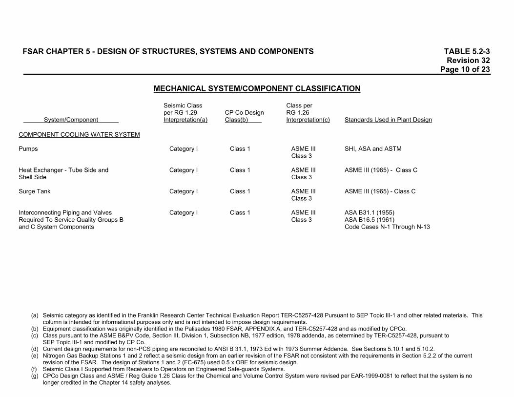
FSAR CHAPTER 5 - DESIGN OF STRUCTURES, SYSTEMS AND COMPONENTS TABLE 5.2-3 Revision 32 Page 10 of 23
MECHANICAL SYSTEM/COMPONENT CLASSIFICATION
Seismic Class Class per per RG 1.29 CP Co Design RG 1.26
System/Component Interpretation(a) Class(b) Interpretation(c) Standards Used in Plant Design
(a) Seismic category as identified in the Franklin Research Center Technical Evaluation Report TER-C5257-428 Pursuant to SEP Topic III-1 and other related materials. This
column is intended for informational purposes only and is not intended to impose design requirements. (b) Equipment classification was originally identified in the Palisades 1980 FSAR, APPENDIX A, and TER-C5257-428 and as modified by CPCo. (c) Class pursuant to the ASME B&PV Code, Section III, Division 1, Subsection NB, 1977 edition, 1978 addenda, as determined by TER-C5257-428, pursuant to
SEP Topic III-1 and modified by CP Co. (d) Current design requirements for non-PCS piping are reconciled to ANSI B 31.1, 1973 Ed with 1973 Summer Addenda. See Sections 5.10.1 and 5.10.2. (e) Nitrogen Gas Backup Stations 1 and 2 reflect a seismic design from an earlier revision of the FSAR not consistent with the requirements in Section 5.2.2 of the current
revision of the FSAR. The design of Stations 1 and 2 (FC-675) used 0.5 x OBE for seismic design. (f) Seismic Class I Supported from Receivers to Operators on Engineered Safe-guards Systems. (g) CPCo Design Class and ASME / Reg Guide 1.26 Class for the Chemical and Volume Control System were revised per EAR-1999-0081 to reflect that the system is no
longer credited in the Chapter 14 safety analyses.
COMPONENT COOLING WATER SYSTEM Pumps Category I Class 1 ASME III SHI, ASA and ASTM
Class 3 Heat Exchanger - Tube Side and Category I Class 1 ASME III ASME III (1965) - Class C Shell Side Class 3 Surge Tank Category I Class 1 ASME III ASME III (1965) - Class C
Class 3 Interconnecting Piping and Valves Category I Class 1 ASME III ASA B31.1 (1955) Required To Service Quality Groups B Class 3 ASA B16.5 (1961) and C System Components Code Cases N-1 Through N-13

FSAR CHAPTER 5 - DESIGN OF STRUCTURES, SYSTEMS AND COMPONENTS TABLE 5.2-3 Revision 32 Page 11 of 23
MECHANICAL SYSTEM/COMPONENT CLASSIFICATION
Seismic Class Class per per RG 1.29 CP Co Design RG 1.26
System/Component Interpretation(a) Class(b) Interpretation(c) Standards Used in Plant Design
(a) Seismic category as identified in the Franklin Research Center Technical Evaluation Report TER-C5257-428 Pursuant to SEP Topic III-1 and other related materials. This
column is intended for informational purposes only and is not intended to impose design requirements. (b) Equipment classification was originally identified in the Palisades 1980 FSAR, APPENDIX A, and TER-C5257-428 and as modified by CPCo. (c) Class pursuant to the ASME B&PV Code, Section III, Division 1, Subsection NB, 1977 edition, 1978 addenda, as determined by TER-C5257-428, pursuant to
SEP Topic III-1 and modified by CP Co. (d) Current design requirements for non-PCS piping are reconciled to ANSI B 31.1, 1973 Ed with 1973 Summer Addenda. See Sections 5.10.1 and 5.10.2. (e) Nitrogen Gas Backup Stations 1 and 2 reflect a seismic design from an earlier revision of the FSAR not consistent with the requirements in Section 5.2.2 of the current
revision of the FSAR. The design of Stations 1 and 2 (FC-675) used 0.5 x OBE for seismic design. (f) Seismic Class I Supported from Receivers to Operators on Engineered Safe-guards Systems. (g) CPCo Design Class and ASME / Reg Guide 1.26 Class for the Chemical and Volume Control System were revised per EAR-1999-0081 to reflect that the system is no
longer credited in the Chapter 14 safety analyses.
SERVICE WATER SYSTEM Pumps Category I Class 1 ASME III SHI, ASA and ASTM
Class 3 Strainers Category I Class 1 ASME III Bechtel Spec M-35
Class 3 Interconnecting Piping and Valves Category I Class 1 ASME III ASA B31.1 (1955) Required To Service Quality Group C Class 3 ASA B16.5 (1961) System Components Code Cases N-1 Through N-13 Noncritical Service Water Noncategory I Class 3 Nonclass HSI, ASTM
ASA B16.5 (1961) ASA B31.1 (1955)
Tie-In for Backup Supply from Category I Class 1 ASME III ASA B31.1 (1955) Fire Protection System Class 3 ASA B16.5 (1961) Code Cases N-1 Through N-13

FSAR CHAPTER 5 - DESIGN OF STRUCTURES, SYSTEMS AND COMPONENTS TABLE 5.2-3 Revision 32 Page 12 of 23
MECHANICAL SYSTEM/COMPONENT CLASSIFICATION
Seismic Class Class per per RG 1.29 CP Co Design RG 1.26
System/Component Interpretation(a) Class(b) Interpretation(c) Standards Used in Plant Design
(a) Seismic category as identified in the Franklin Research Center Technical Evaluation Report TER-C5257-428 Pursuant to SEP Topic III-1 and other related materials. This
column is intended for informational purposes only and is not intended to impose design requirements. (b) Equipment classification was originally identified in the Palisades 1980 FSAR, APPENDIX A, and TER-C5257-428 and as modified by CPCo. (c) Class pursuant to the ASME B&PV Code, Section III, Division 1, Subsection NB, 1977 edition, 1978 addenda, as determined by TER-C5257-428, pursuant to
SEP Topic III-1 and modified by CP Co. (d) Current design requirements for non-PCS piping are reconciled to ANSI B 31.1, 1973 Ed with 1973 Summer Addenda. See Sections 5.10.1 and 5.10.2. (e) Nitrogen Gas Backup Stations 1 and 2 reflect a seismic design from an earlier revision of the FSAR not consistent with the requirements in Section 5.2.2 of the current
revision of the FSAR. The design of Stations 1 and 2 (FC-675) used 0.5 x OBE for seismic design. (f) Seismic Class I Supported from Receivers to Operators on Engineered Safe-guards Systems. (g) CPCo Design Class and ASME / Reg Guide 1.26 Class for the Chemical and Volume Control System were revised per EAR-1999-0081 to reflect that the system is no
longer credited in the Chapter 14 safety analyses.
SPENT FUEL POOL COOLING SYSTEM Cooling Pumps Category I Class 1 ASME III HSI
Class 3 Heat Exchanger Category I Class 1 ASME III ASME III, Class C and
Class 3 ASME VIII, Para UW-2 Recirc Booster Pump Category I Class 1 ASME III HSI Class 3 Demineralizer Category I Class 1 ASME III ASME III, Class C and Class 3 ASME VIII, Para UW-2 Piping, Valves and Fittings Category I Class 1 ASME III ASA B31.1 and ASA B16.5 (except Reactor Cavity Tilt Drain Pipe Class 3 which is RG 1.26, Nonclass)

FSAR CHAPTER 5 - DESIGN OF STRUCTURES, SYSTEMS AND COMPONENTS TABLE 5.2-3 Revision 32 Page 13 of 23
MECHANICAL SYSTEM/COMPONENT CLASSIFICATION
Seismic Class Class per per RG 1.29 CP Co Design RG 1.26
System/Component Interpretation(a) Class(b) Interpretation(c) Standards Used in Plant Design
(a) Seismic category as identified in the Franklin Research Center Technical Evaluation Report TER-C5257-428 Pursuant to SEP Topic III-1 and other related materials. This
column is intended for informational purposes only and is not intended to impose design requirements. (b) Equipment classification was originally identified in the Palisades 1980 FSAR, APPENDIX A, and TER-C5257-428 and as modified by CPCo. (c) Class pursuant to the ASME B&PV Code, Section III, Division 1, Subsection NB, 1977 edition, 1978 addenda, as determined by TER-C5257-428, pursuant to
SEP Topic III-1 and modified by CP Co. (d) Current design requirements for non-PCS piping are reconciled to ANSI B 31.1, 1973 Ed with 1973 Summer Addenda. See Sections 5.10.1 and 5.10.2. (e) Nitrogen Gas Backup Stations 1 and 2 reflect a seismic design from an earlier revision of the FSAR not consistent with the requirements in Section 5.2.2 of the current
revision of the FSAR. The design of Stations 1 and 2 (FC-675) used 0.5 x OBE for seismic design. (f) Seismic Class I Supported from Receivers to Operators on Engineered Safe-guards Systems. (g) CPCo Design Class and ASME / Reg Guide 1.26 Class for the Chemical and Volume Control System were revised per EAR-1999-0081 to reflect that the system is no
longer credited in the Chapter 14 safety analyses.
MAIN STEAM SYSTEM Interconnecting Piping and Valves Category I Class 1 ASME III ASA B31.1 (1955) Comprising Main Steam Lines Extending Class 2 ASA B16.5 (1961) From the Secondary Side of the Steam Code Cases N-1 Through N-13 Generators up to and Including the Outermost Containment Isolation Valve in Each Main Steam Line and Connected Piping up to and Including the First Valve That Is Normally Closed or Capable of Automatic Closure During All Modes of Normal Reactor Operation Main Steam Piping Outside Containment Category I Class 2 Nonclass ASA B31.1 (1955) Between the Main Steam Isolation Valves ASA B16.5 (1961) and the Steam Takeoff Block Valves Code Cases N-1 Through N-13 Remainder of System Noncategory I Class 3 Nonclass - Atmospheric Dump Category I Class 1 ASME III ASA B31.1 (1955)
Class 2 ASA B16.5 (1961) Air Supply to Dumps Category I Class 1 Nonclass -

FSAR CHAPTER 5 - DESIGN OF STRUCTURES, SYSTEMS AND COMPONENTS TABLE 5.2-3 Revision 32 Page 14 of 23
MECHANICAL SYSTEM/COMPONENT CLASSIFICATION
Seismic Class Class per per RG 1.29 CP Co Design RG 1.26
System/Component Interpretation(a) Class(b) Interpretation(c) Standards Used in Plant Design
(a) Seismic category as identified in the Franklin Research Center Technical Evaluation Report TER-C5257-428 Pursuant to SEP Topic III-1 and other related materials. This
column is intended for informational purposes only and is not intended to impose design requirements. (b) Equipment classification was originally identified in the Palisades 1980 FSAR, APPENDIX A, and TER-C5257-428 and as modified by CPCo. (c) Class pursuant to the ASME B&PV Code, Section III, Division 1, Subsection NB, 1977 edition, 1978 addenda, as determined by TER-C5257-428, pursuant to
SEP Topic III-1 and modified by CP Co. (d) Current design requirements for non-PCS piping are reconciled to ANSI B 31.1, 1973 Ed with 1973 Summer Addenda. See Sections 5.10.1 and 5.10.2. (e) Nitrogen Gas Backup Stations 1 and 2 reflect a seismic design from an earlier revision of the FSAR not consistent with the requirements in Section 5.2.2 of the current
revision of the FSAR. The design of Stations 1 and 2 (FC-675) used 0.5 x OBE for seismic design. (f) Seismic Class I Supported from Receivers to Operators on Engineered Safe-guards Systems. (g) CPCo Design Class and ASME / Reg Guide 1.26 Class for the Chemical and Volume Control System were revised per EAR-1999-0081 to reflect that the system is no
longer credited in the Chapter 14 safety analyses.
Safety Valves Category I Class 1 ASME III ASA B31.1 (1955) Class 2 ASA B16.5 (1961)
Code Cases N-1 Through N-13 to ASME Steam Generator Blowdown and Recirculation Category I Class 1 ASME III ANSI B31.1 - 1973 Design Lines, Extending from the Secondary Side Class 2 ASME III - 1986 Shop of the SG through the Containment Fabrication and Materials Penetration Penetration (For Piping from Outermost USAS B 31.1 - 1967 Containment Isolation Valve, Refer to Installation "Feedwater System") CONDENSATE SYSTEM Noncategory I Class 3 Nonclass ASME VIII
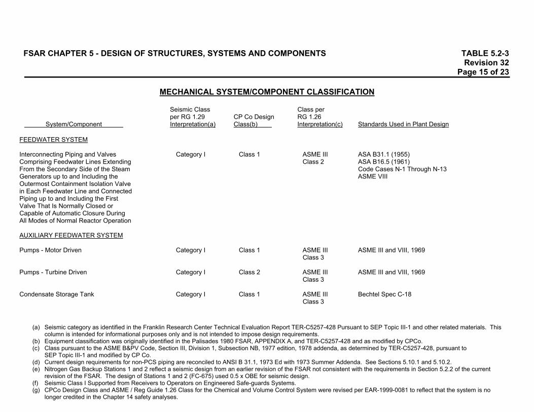
FSAR CHAPTER 5 - DESIGN OF STRUCTURES, SYSTEMS AND COMPONENTS TABLE 5.2-3 Revision 32 Page 15 of 23
MECHANICAL SYSTEM/COMPONENT CLASSIFICATION
Seismic Class Class per per RG 1.29 CP Co Design RG 1.26
System/Component Interpretation(a) Class(b) Interpretation(c) Standards Used in Plant Design
(a) Seismic category as identified in the Franklin Research Center Technical Evaluation Report TER-C5257-428 Pursuant to SEP Topic III-1 and other related materials. This
column is intended for informational purposes only and is not intended to impose design requirements. (b) Equipment classification was originally identified in the Palisades 1980 FSAR, APPENDIX A, and TER-C5257-428 and as modified by CPCo. (c) Class pursuant to the ASME B&PV Code, Section III, Division 1, Subsection NB, 1977 edition, 1978 addenda, as determined by TER-C5257-428, pursuant to
SEP Topic III-1 and modified by CP Co. (d) Current design requirements for non-PCS piping are reconciled to ANSI B 31.1, 1973 Ed with 1973 Summer Addenda. See Sections 5.10.1 and 5.10.2. (e) Nitrogen Gas Backup Stations 1 and 2 reflect a seismic design from an earlier revision of the FSAR not consistent with the requirements in Section 5.2.2 of the current
revision of the FSAR. The design of Stations 1 and 2 (FC-675) used 0.5 x OBE for seismic design. (f) Seismic Class I Supported from Receivers to Operators on Engineered Safe-guards Systems. (g) CPCo Design Class and ASME / Reg Guide 1.26 Class for the Chemical and Volume Control System were revised per EAR-1999-0081 to reflect that the system is no
longer credited in the Chapter 14 safety analyses.
FEEDWATER SYSTEM Interconnecting Piping and Valves Category I Class 1 ASME III ASA B31.1 (1955) Comprising Feedwater Lines Extending Class 2 ASA B16.5 (1961) From the Secondary Side of the Steam Code Cases N-1 Through N-13 Generators up to and Including the ASME VIII Outermost Containment Isolation Valve in Each Feedwater Line and Connected Piping up to and Including the First Valve That Is Normally Closed or Capable of Automatic Closure During All Modes of Normal Reactor Operation AUXILIARY FEEDWATER SYSTEM Pumps - Motor Driven Category I Class 1 ASME III ASME III and VIII, 1969
Class 3 Pumps - Turbine Driven Category I Class 2 ASME III ASME III and VIII, 1969
Class 3 Condensate Storage Tank Category I Class 1 ASME III Bechtel Spec C-18
Class 3
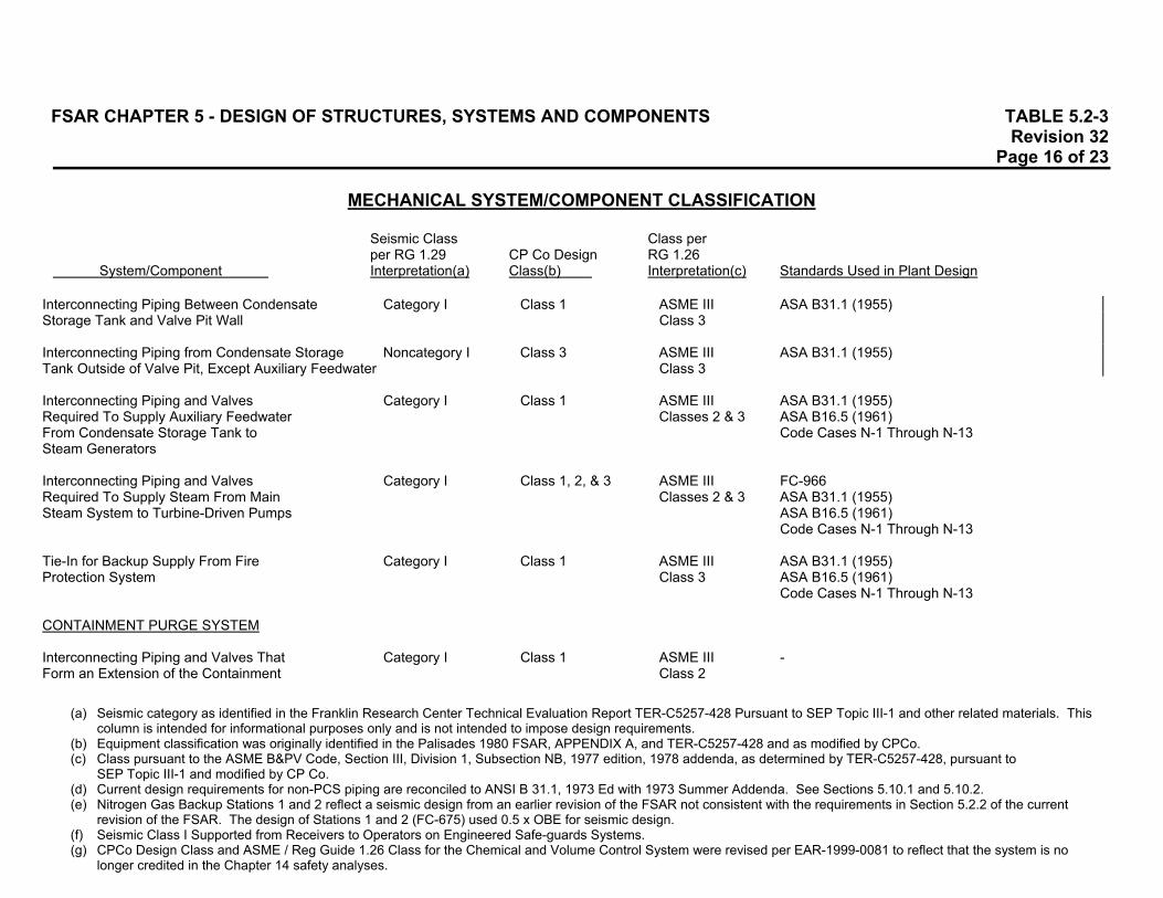
FSAR CHAPTER 5 - DESIGN OF STRUCTURES, SYSTEMS AND COMPONENTS TABLE 5.2-3 Revision 32 Page 16 of 23
MECHANICAL SYSTEM/COMPONENT CLASSIFICATION
Seismic Class Class per per RG 1.29 CP Co Design RG 1.26
System/Component Interpretation(a) Class(b) Interpretation(c) Standards Used in Plant Design
(a) Seismic category as identified in the Franklin Research Center Technical Evaluation Report TER-C5257-428 Pursuant to SEP Topic III-1 and other related materials. This
column is intended for informational purposes only and is not intended to impose design requirements. (b) Equipment classification was originally identified in the Palisades 1980 FSAR, APPENDIX A, and TER-C5257-428 and as modified by CPCo. (c) Class pursuant to the ASME B&PV Code, Section III, Division 1, Subsection NB, 1977 edition, 1978 addenda, as determined by TER-C5257-428, pursuant to
SEP Topic III-1 and modified by CP Co. (d) Current design requirements for non-PCS piping are reconciled to ANSI B 31.1, 1973 Ed with 1973 Summer Addenda. See Sections 5.10.1 and 5.10.2. (e) Nitrogen Gas Backup Stations 1 and 2 reflect a seismic design from an earlier revision of the FSAR not consistent with the requirements in Section 5.2.2 of the current
revision of the FSAR. The design of Stations 1 and 2 (FC-675) used 0.5 x OBE for seismic design. (f) Seismic Class I Supported from Receivers to Operators on Engineered Safe-guards Systems. (g) CPCo Design Class and ASME / Reg Guide 1.26 Class for the Chemical and Volume Control System were revised per EAR-1999-0081 to reflect that the system is no
longer credited in the Chapter 14 safety analyses.
Interconnecting Piping Between Condensate Category I Class 1 ASME III ASA B31.1 (1955) Storage Tank and Valve Pit Wall Class 3 Interconnecting Piping from Condensate Storage Noncategory I Class 3 ASME III ASA B31.1 (1955) Tank Outside of Valve Pit, Except Auxiliary Feedwater Class 3 Interconnecting Piping and Valves Category I Class 1 ASME III ASA B31.1 (1955) Required To Supply Auxiliary Feedwater Classes 2 & 3 ASA B16.5 (1961) From Condensate Storage Tank to Code Cases N-1 Through N-13 Steam Generators Interconnecting Piping and Valves Category I Class 1, 2, & 3 ASME III FC-966 Required To Supply Steam From Main Classes 2 & 3 ASA B31.1 (1955) Steam System to Turbine-Driven Pumps ASA B16.5 (1961)
Code Cases N-1 Through N-13 Tie-In for Backup Supply From Fire Category I Class 1 ASME III ASA B31.1 (1955) Protection System Class 3 ASA B16.5 (1961)
Code Cases N-1 Through N-13 CONTAINMENT PURGE SYSTEM Interconnecting Piping and Valves That Category I Class 1 ASME III - Form an Extension of the Containment Class 2

FSAR CHAPTER 5 - DESIGN OF STRUCTURES, SYSTEMS AND COMPONENTS TABLE 5.2-3 Revision 32 Page 17 of 23
MECHANICAL SYSTEM/COMPONENT CLASSIFICATION
Seismic Class Class per per RG 1.29 CP Co Design RG 1.26
System/Component Interpretation(a) Class(b) Interpretation(c) Standards Used in Plant Design
(a) Seismic category as identified in the Franklin Research Center Technical Evaluation Report TER-C5257-428 Pursuant to SEP Topic III-1 and other related materials. This
column is intended for informational purposes only and is not intended to impose design requirements. (b) Equipment classification was originally identified in the Palisades 1980 FSAR, APPENDIX A, and TER-C5257-428 and as modified by CPCo. (c) Class pursuant to the ASME B&PV Code, Section III, Division 1, Subsection NB, 1977 edition, 1978 addenda, as determined by TER-C5257-428, pursuant to
SEP Topic III-1 and modified by CP Co. (d) Current design requirements for non-PCS piping are reconciled to ANSI B 31.1, 1973 Ed with 1973 Summer Addenda. See Sections 5.10.1 and 5.10.2. (e) Nitrogen Gas Backup Stations 1 and 2 reflect a seismic design from an earlier revision of the FSAR not consistent with the requirements in Section 5.2.2 of the current
revision of the FSAR. The design of Stations 1 and 2 (FC-675) used 0.5 x OBE for seismic design. (f) Seismic Class I Supported from Receivers to Operators on Engineered Safe-guards Systems. (g) CPCo Design Class and ASME / Reg Guide 1.26 Class for the Chemical and Volume Control System were revised per EAR-1999-0081 to reflect that the system is no
longer credited in the Chapter 14 safety analyses.
Boundary up to and Including the Outermost Containment Isolation Valve CONTAINMENT COOLING SYSTEM Containment Fan Coolers Category I Class 1 ASME III Bechtel Spec M-59 and M-60A and (Fans and Cooling Coils) Class 3 FSAR Update Tables 6-9, 6-10 and 9-16 Necessary Portions of System Category I Class 1 Nonclass - Ductwork and Dampers CONTAINMENT ISOLATION SYSTEM Interconnecting Piping and Valves of Category I Class 1 ASME III ASA B31.1 (1955) the Reactor Coolant Pressure Boundary Class 2 ASA B16.5 (1961) That Penetrate the Containment up to Code Cases N-1 Through N-13 and Including the Outermost Containment Isolation Valve Interconnecting Piping and Valves of Category I Class 1 ASME III ASA B31.1 (1955) Quality Group B, C or D System That Class 2 ASA B16.5 (1961) Penetrate the Containment From the Code Cases N-1 Through N-13 First Isolation Valve Inside Containment up to and Including the Outermost

FSAR CHAPTER 5 - DESIGN OF STRUCTURES, SYSTEMS AND COMPONENTS TABLE 5.2-3 Revision 32 Page 18 of 23
MECHANICAL SYSTEM/COMPONENT CLASSIFICATION
Seismic Class Class per per RG 1.29 CP Co Design RG 1.26
System/Component Interpretation(a) Class(b) Interpretation(c) Standards Used in Plant Design
(a) Seismic category as identified in the Franklin Research Center Technical Evaluation Report TER-C5257-428 Pursuant to SEP Topic III-1 and other related materials. This
column is intended for informational purposes only and is not intended to impose design requirements. (b) Equipment classification was originally identified in the Palisades 1980 FSAR, APPENDIX A, and TER-C5257-428 and as modified by CPCo. (c) Class pursuant to the ASME B&PV Code, Section III, Division 1, Subsection NB, 1977 edition, 1978 addenda, as determined by TER-C5257-428, pursuant to
SEP Topic III-1 and modified by CP Co. (d) Current design requirements for non-PCS piping are reconciled to ANSI B 31.1, 1973 Ed with 1973 Summer Addenda. See Sections 5.10.1 and 5.10.2. (e) Nitrogen Gas Backup Stations 1 and 2 reflect a seismic design from an earlier revision of the FSAR not consistent with the requirements in Section 5.2.2 of the current
revision of the FSAR. The design of Stations 1 and 2 (FC-675) used 0.5 x OBE for seismic design. (f) Seismic Class I Supported from Receivers to Operators on Engineered Safe-guards Systems. (g) CPCo Design Class and ASME / Reg Guide 1.26 Class for the Chemical and Volume Control System were revised per EAR-1999-0081 to reflect that the system is no
longer credited in the Chapter 14 safety analyses.
Containment Isolation Valve FIRE PROTECTION SYSTEM Pump - Diesel Driven, Including Its Noncategory I Class 2 Nonclass NFPA HSI 13, 1968 Auxiliary Equipment and Associated NFPA 14 Piping NFPA 15, 1962
NFPA 20, 1959 NFPA 24, 1965
All Other Components Noncategory I Class 3 Nonclass NFPA HSI 13, 1968
NFPA 14 NFPA 15, 1962 NFPA 20, 1959 NFPA 24, 1965
FP Piping Within Intake Structure Noncategory I Class 2 Nonclass HSI

FSAR CHAPTER 5 - DESIGN OF STRUCTURES, SYSTEMS AND COMPONENTS TABLE 5.2-3 Revision 32 Page 19 of 23
MECHANICAL SYSTEM/COMPONENT CLASSIFICATION
Seismic Class Class per per RG 1.29 CP Co Design RG 1.26
System/Component Interpretation(a) Class(b) Interpretation(c) Standards Used in Plant Design
(a) Seismic category as identified in the Franklin Research Center Technical Evaluation Report TER-C5257-428 Pursuant to SEP Topic III-1 and other related materials. This
column is intended for informational purposes only and is not intended to impose design requirements. (b) Equipment classification was originally identified in the Palisades 1980 FSAR, APPENDIX A, and TER-C5257-428 and as modified by CPCo. (c) Class pursuant to the ASME B&PV Code, Section III, Division 1, Subsection NB, 1977 edition, 1978 addenda, as determined by TER-C5257-428, pursuant to
SEP Topic III-1 and modified by CP Co. (d) Current design requirements for non-PCS piping are reconciled to ANSI B 31.1, 1973 Ed with 1973 Summer Addenda. See Sections 5.10.1 and 5.10.2. (e) Nitrogen Gas Backup Stations 1 and 2 reflect a seismic design from an earlier revision of the FSAR not consistent with the requirements in Section 5.2.2 of the current
revision of the FSAR. The design of Stations 1 and 2 (FC-675) used 0.5 x OBE for seismic design. (f) Seismic Class I Supported from Receivers to Operators on Engineered Safe-guards Systems. (g) CPCo Design Class and ASME / Reg Guide 1.26 Class for the Chemical and Volume Control System were revised per EAR-1999-0081 to reflect that the system is no
longer credited in the Chapter 14 safety analyses.
AIR SYSTEM Plant Instrument and Service Air Noncategory I Class 2 & 3 Nonclass ASME VIII, ASA B31.1 High-Pressure Air Category I (f) Class 2 Nonclass ASME VIII, ASA B31.1 Portion of HP Air Associated With Category I (f) Class 1 Nonclass ASME VIII, ASA B31.1 Engineered Safeguards Nitrogen Gas Backup (e) Noncategory I Class 2 Nonclass - Station 1 to CV0727 and CV0749 Station 2 to CV0522B Nitrogen Backup System Category I Class 1 Nonclass ASA B31.1 (1955) Station 1A to CV0847 Station 3A to CV3027 CV3056 Station 3B to CV0824 CV3070
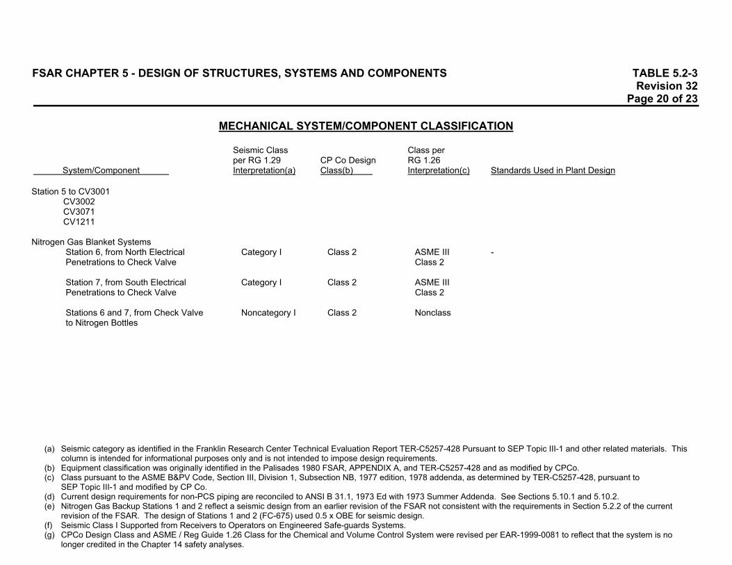
FSAR CHAPTER 5 - DESIGN OF STRUCTURES, SYSTEMS AND COMPONENTS TABLE 5.2-3 Revision 32 Page 20 of 23
MECHANICAL SYSTEM/COMPONENT CLASSIFICATION
Seismic Class Class per per RG 1.29 CP Co Design RG 1.26
System/Component Interpretation(a) Class(b) Interpretation(c) Standards Used in Plant Design
(a) Seismic category as identified in the Franklin Research Center Technical Evaluation Report TER-C5257-428 Pursuant to SEP Topic III-1 and other related materials. This
column is intended for informational purposes only and is not intended to impose design requirements. (b) Equipment classification was originally identified in the Palisades 1980 FSAR, APPENDIX A, and TER-C5257-428 and as modified by CPCo. (c) Class pursuant to the ASME B&PV Code, Section III, Division 1, Subsection NB, 1977 edition, 1978 addenda, as determined by TER-C5257-428, pursuant to
SEP Topic III-1 and modified by CP Co. (d) Current design requirements for non-PCS piping are reconciled to ANSI B 31.1, 1973 Ed with 1973 Summer Addenda. See Sections 5.10.1 and 5.10.2. (e) Nitrogen Gas Backup Stations 1 and 2 reflect a seismic design from an earlier revision of the FSAR not consistent with the requirements in Section 5.2.2 of the current
revision of the FSAR. The design of Stations 1 and 2 (FC-675) used 0.5 x OBE for seismic design. (f) Seismic Class I Supported from Receivers to Operators on Engineered Safe-guards Systems. (g) CPCo Design Class and ASME / Reg Guide 1.26 Class for the Chemical and Volume Control System were revised per EAR-1999-0081 to reflect that the system is no
longer credited in the Chapter 14 safety analyses.
Station 5 to CV3001 CV3002 CV3071 CV1211 Nitrogen Gas Blanket Systems Station 6, from North Electrical Category I Class 2 ASME III - Penetrations to Check Valve Class 2 Station 7, from South Electrical Category I Class 2 ASME III Penetrations to Check Valve Class 2 Stations 6 and 7, from Check Valve Noncategory I Class 2 Nonclass to Nitrogen Bottles
FSAR CHAPTER 5 - DESIGN OF STRUCTURES, SYSTEMS AND COMPONENTS TABLE 5.2-3 Revision 32 Page 21 of 23
MECHANICAL SYSTEM/COMPONENT CLASSIFICATION
Seismic Class Class per per RG 1.29 CP Co Design RG 1.26
System/Component Interpretation(a) Class(b) Interpretation(c) Standards Used in Plant Design
(a) Seismic category as identified in the Franklin Research Center Technical Evaluation Report TER-C5257-428 Pursuant to SEP Topic III-1 and other related materials. This
column is intended for informational purposes only and is not intended to impose design requirements. (b) Equipment classification was originally identified in the Palisades 1980 FSAR, APPENDIX A, and TER-C5257-428 and as modified by CPCo. (c) Class pursuant to the ASME B&PV Code, Section III, Division 1, Subsection NB, 1977 edition, 1978 addenda, as determined by TER-C5257-428, pursuant to
SEP Topic III-1 and modified by CP Co. (d) Current design requirements for non-PCS piping are reconciled to ANSI B 31.1, 1973 Ed with 1973 Summer Addenda. See Sections 5.10.1 and 5.10.2. (e) Nitrogen Gas Backup Stations 1 and 2 reflect a seismic design from an earlier revision of the FSAR not consistent with the requirements in Section 5.2.2 of the current
revision of the FSAR. The design of Stations 1 and 2 (FC-675) used 0.5 x OBE for seismic design. (f) Seismic Class I Supported from Receivers to Operators on Engineered Safe-guards Systems. (g) CPCo Design Class and ASME / Reg Guide 1.26 Class for the Chemical and Volume Control System were revised per EAR-1999-0081 to reflect that the system is no
longer credited in the Chapter 14 safety analyses.
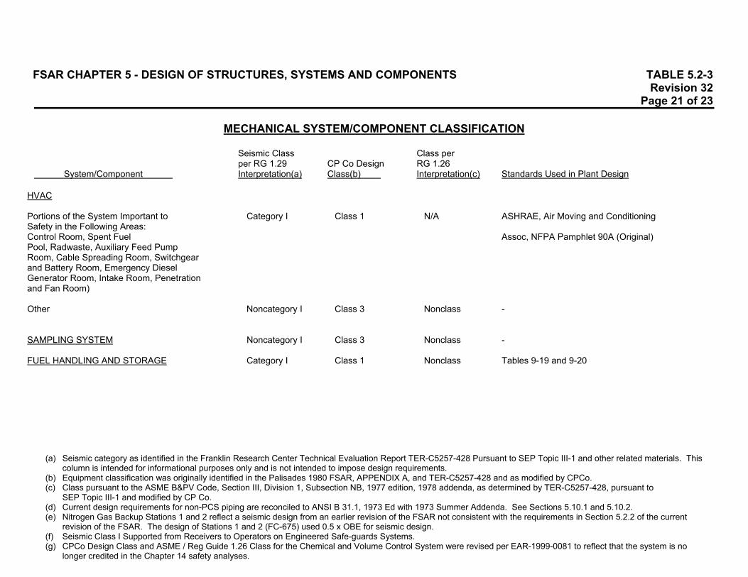
HVAC Portions of the System Important to Category I Class 1 N/A ASHRAE, Air Moving and Conditioning Safety in the Following Areas: Control Room, Spent Fuel Assoc, NFPA Pamphlet 90A (Original) Pool, Radwaste, Auxiliary Feed Pump Room, Cable Spreading Room, Switchgear and Battery Room, Emergency Diesel Generator Room, Intake Room, Penetration and Fan Room) Other Noncategory I Class 3 Nonclass - SAMPLING SYSTEM Noncategory I Class 3 Nonclass - FUEL HANDLING AND STORAGE Category I Class 1 Nonclass Tables 9-19 and 9-20

FSAR CHAPTER 5 - DESIGN OF STRUCTURES, SYSTEMS AND COMPONENTS TABLE 5.2-3 Revision 32 Page 22 of 23
MECHANICAL SYSTEM/COMPONENT CLASSIFICATION
Seismic Class Class per per RG 1.29 CP Co Design RG 1.26
System/Component Interpretation(a) Class(b) Interpretation(c) Standards Used in Plant Design
(a) Seismic category as identified in the Franklin Research Center Technical Evaluation Report TER-C5257-428 Pursuant to SEP Topic III-1 and other related materials. This
column is intended for informational purposes only and is not intended to impose design requirements. (b) Equipment classification was originally identified in the Palisades 1980 FSAR, APPENDIX A, and TER-C5257-428 and as modified by CPCo. (c) Class pursuant to the ASME B&PV Code, Section III, Division 1, Subsection NB, 1977 edition, 1978 addenda, as determined by TER-C5257-428, pursuant to
SEP Topic III-1 and modified by CP Co. (d) Current design requirements for non-PCS piping are reconciled to ANSI B 31.1, 1973 Ed with 1973 Summer Addenda. See Sections 5.10.1 and 5.10.2. (e) Nitrogen Gas Backup Stations 1 and 2 reflect a seismic design from an earlier revision of the FSAR not consistent with the requirements in Section 5.2.2 of the current
revision of the FSAR. The design of Stations 1 and 2 (FC-675) used 0.5 x OBE for seismic design. (f) Seismic Class I Supported from Receivers to Operators on Engineered Safe-guards Systems. (g) CPCo Design Class and ASME / Reg Guide 1.26 Class for the Chemical and Volume Control System were revised per EAR-1999-0081 to reflect that the system is no
longer credited in the Chapter 14 safety analyses.
CIRCULATING WATER SYSTEM Cooling Towers Noncategory I Class 3 Nonclass UBC Makeup Pumps Noncategory I Class 3 Nonclass Piping Noncategory I Class 3 Nonclass - RADIOACTIVE WASTE SYSTEM Liquid and Gaseous (Original) Noncategory I Classes 1 & 2 ASME VIII ASME III, Class C, ASME VIII, ASA B16.5 Liquid and Gaseous (Modified) Components Added During July 1, 1973 Noncategory I Class 2 ASME VIII ASME III, Class 3 (1971), ANSI B31.1 (1967), Except Gas Decay Tanks API 620, API 650 (Both 1970) Processing Piping Noncategory I Class 2 ASME VIII ASME III, Class 3, 1971 Gas Decay Tanks - Class 3 ASME VIII

FSAR CHAPTER 5 - DESIGN OF STRUCTURES, SYSTEMS AND COMPONENTS TABLE 5.2-3 Revision 32 Page 23 of 23
MECHANICAL SYSTEM/COMPONENT CLASSIFICATION
Seismic Class Class per per RG 1.29 CP Co Design RG 1.26
System/Component Interpretation(a) Class(b) Interpretation(c) Standards Used in Plant Design
(a) Seismic category as identified in the Franklin Research Center Technical Evaluation Report TER-C5257-428 Pursuant to SEP Topic III-1 and other related materials. This
column is intended for informational purposes only and is not intended to impose design requirements. (b) Equipment classification was originally identified in the Palisades 1980 FSAR, APPENDIX A, and TER-C5257-428 and as modified by CPCo. (c) Class pursuant to the ASME B&PV Code, Section III, Division 1, Subsection NB, 1977 edition, 1978 addenda, as determined by TER-C5257-428, pursuant to
SEP Topic III-1 and modified by CP Co. (d) Current design requirements for non-PCS piping are reconciled to ANSI B 31.1, 1973 Ed with 1973 Summer Addenda. See Sections 5.10.1 and 5.10.2. (e) Nitrogen Gas Backup Stations 1 and 2 reflect a seismic design from an earlier revision of the FSAR not consistent with the requirements in Section 5.2.2 of the current
revision of the FSAR. The design of Stations 1 and 2 (FC-675) used 0.5 x OBE for seismic design. (f) Seismic Class I Supported from Receivers to Operators on Engineered Safe-guards Systems. (g) CPCo Design Class and ASME / Reg Guide 1.26 Class for the Chemical and Volume Control System were revised per EAR-1999-0081 to reflect that the system is no
longer credited in the Chapter 14 safety analyses.
Solid Radwaste (Original) Noncategory I Class 1 ASME VIII - Solid Radwaste (Modified) Tanks Noncategory I Class 2 API 650 API 650 Heat Exchangers/Coolers Noncategory I Class 2 ASME VIII ASME VIII, 77, W79a Piping/Strainers/Pumps Noncategory I Class 2 ANSI B31.1 ANSI B31.1 DIESEL GENERATOR OIL STORAGE Supply Piping Category I Class 1 - ANSI B31.1 Storage Tank Category I Class 1 - UL 58

FSAR CHAPTER 5 - DESIGN OF STRUCTURES, SYSTEMS AND COMPONENTS TABLE 5.2-4 Revision 29 Page 1 of 6
ELECTRICAL SYSTEMS/COMPONENT CLASSIFICATION(a) SYSTEM / COMPONENT(b) SAFETY CLASS 1E(c)
(a) Safety Class 1E components are Seismic Category I per Regulatory Guide 1.29. (b) Refer to Chapters 7 and 8 for description of components listed. (c) Refer to Chapter 8 definition. (d) These components have a mix of Class 1E and Nonclass 1E circuits per Plant safety classification (Q-List). (e) Components associated with the routing of plant circuits have been assigned safety classifications and channels
consistent with the FSAR commitments. These assignments may be found in the Circuit\Raceway Schedule database. (f) Containment Cooling Fan V-1A, V-2A, V-3A, and V-4A motors are Safety Class 1E. The motors for containment cooling
fans V-1B, V-2B, V-3B, and V-4B are not Safety Class 1E. (g) Charging pumps are supplied from a Safety Class 1E bus, but Chapter 14 safety analyses take no credit for them so they
are not required to be Safety Class 1E.
1. Emergency Generators Generator Skids 1-1 and 1-2 Yes Generator Control Panels (G20, G21, G30, G31) Yes Static Exciters (C22, C26) Yes
2. 2,400 V Bus System 2,400 V Buses 1C and 1D (A11, A12) Yes Relay Test Panels (C18A, C19A) No Breaker Test Panels (C18, C19) No Terminal Panels Near Switchgear 1D (J9401, JL274, JL275) Yes

FSAR CHAPTER 5 - DESIGN OF STRUCTURES, SYSTEMS AND COMPONENTS TABLE 5.2-4 Revision 29 Page 2 of 6
ELECTRICAL SYSTEMS/COMPONENT CLASSIFICATION(a) SYSTEM / COMPONENT(b) SAFETY CLASS 1E(c)
(a) Safety Class 1E components are Seismic Category I per Regulatory Guide 1.29. (b) Refer to Chapters 7 and 8 for description of components listed. (c) Refer to Chapter 8 definition. (d) These components have a mix of Class 1E and Nonclass 1E circuits per Plant safety classification (Q-List). (e) Components associated with the routing of plant circuits have been assigned safety classifications and channels
consistent with the FSAR commitments. These assignments may be found in the Circuit\Raceway Schedule database. (f) Containment Cooling Fan V-1A, V-2A, V-3A, and V-4A motors are Safety Class 1E. The motors for containment cooling
fans V-1B, V-2B, V-3B, and V-4B are not Safety Class 1E. (g) Charging pumps are supplied from a Safety Class 1E bus, but Chapter 14 safety analyses take no credit for them so they
are not required to be Safety Class 1E.
3. 2,400/480 V Station Power Transformers Transformer 11 (X11) Yes Transformer 12 (X12) Yes Transformer 19 (X19) Yes Transformer 20 (X20) Yes
4. 480 V Bus System 480 V Buses 11, 12, 19 and 20 Switchgear (B11, B12, B19, B20) Yes 480 V Motor Control Centers 1, 2, 21, 22, 23, 24, 25 and 26 (B01, B02, B21, B22, B23, B24, B25, B26) Yes 480 V Motor Control Centers 7 and 8 (B07, B08) No Pressurizer Heater Transformers 15 and 16 (X15, X16) No 480 V Buses 15 and 16 Switchgear SCR Controls (B15, B16) No Control Rod Drive Transformers 1 and 2 (X45, X46) No
FSAR CHAPTER 5 - DESIGN OF STRUCTURES, SYSTEMS AND COMPONENTS TABLE 5.2-4 Revision 29 Page 3 of 6
ELECTRICAL SYSTEMS/COMPONENT CLASSIFICATION(a) SYSTEM / COMPONENT(b) SAFETY CLASS 1E(c)
(a) Safety Class 1E components are Seismic Category I per Regulatory Guide 1.29. (b) Refer to Chapters 7 and 8 for description of components listed. (c) Refer to Chapter 8 definition. (d) These components have a mix of Class 1E and Nonclass 1E circuits per Plant safety classification (Q-List). (e) Components associated with the routing of plant circuits have been assigned safety classifications and channels
consistent with the FSAR commitments. These assignments may be found in the Circuit\Raceway Schedule database. (f) Containment Cooling Fan V-1A, V-2A, V-3A, and V-4A motors are Safety Class 1E. The motors for containment cooling
fans V-1B, V-2B, V-3B, and V-4B are not Safety Class 1E. (g) Charging pumps are supplied from a Safety Class 1E bus, but Chapter 14 safety analyses take no credit for them so they
are not required to be Safety Class 1E.
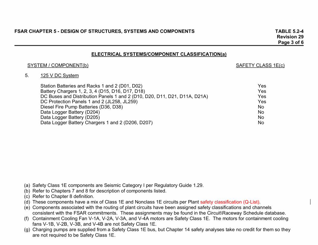
5. 125 V DC System Station Batteries and Racks 1 and 2 (D01, D02) Yes Battery Chargers 1, 2, 3, 4 (D15, D16, D17, D18) Yes DC Buses and Distribution Panels 1 and 2 (D10, D20, D11, D21, D11A, D21A) Yes DC Protection Panels 1 and 2 (JL258, JL259) Yes Diesel Fire Pump Batteries (D36, D38) No Data Logger Battery (D204) No Data Logger Battery (D205) No Data Logger Battery Chargers 1 and 2 (D206, D207) No

FSAR CHAPTER 5 - DESIGN OF STRUCTURES, SYSTEMS AND COMPONENTS TABLE 5.2-4 Revision 29 Page 4 of 6
ELECTRICAL SYSTEMS/COMPONENT CLASSIFICATION(a) SYSTEM / COMPONENT(b) SAFETY CLASS 1E(c)
(a) Safety Class 1E components are Seismic Category I per Regulatory Guide 1.29. (b) Refer to Chapters 7 and 8 for description of components listed. (c) Refer to Chapter 8 definition. (d) These components have a mix of Class 1E and Nonclass 1E circuits per Plant safety classification (Q-List). (e) Components associated with the routing of plant circuits have been assigned safety classifications and channels
consistent with the FSAR commitments. These assignments may be found in the Circuit\Raceway Schedule database. (f) Containment Cooling Fan V-1A, V-2A, V-3A, and V-4A motors are Safety Class 1E. The motors for containment cooling
fans V-1B, V-2B, V-3B, and V-4B are not Safety Class 1E. (g) Charging pumps are supplied from a Safety Class 1E bus, but Chapter 14 safety analyses take no credit for them so they
are not required to be Safety Class 1E.
6. 120 V AC System Inverters 1, 2, 3, 4 (D06, D07, D08, D09) Yes Preferred AC Buses 1, 2, 3, 4 (Y10, Y20, Y30, Y40) Yes Instrument AC Transformers 1 and 2 (X21, X22) No Instrument AC Bus (Y01) No Bypass Regulator (Part of Y01) No Data Loggers Inverters 5 and 6 and Static Switch (Y210, Y220, Y230) No Data Logger Bypass Switch (S9003) No
7. Electrical Control Panels Control Room Panel (C01) - Turbine Generator Controls Partial(d) Control Room Panel (C04) - Auxiliary Power Controls Yes Control Room Panel (C51) - Switchyard Controls No

FSAR CHAPTER 5 - DESIGN OF STRUCTURES, SYSTEMS AND COMPONENTS TABLE 5.2-4 Revision 29 Page 5 of 6
ELECTRICAL SYSTEMS/COMPONENT CLASSIFICATION(a) SYSTEM / COMPONENT(b) SAFETY CLASS 1E(c)
(a) Safety Class 1E components are Seismic Category I per Regulatory Guide 1.29. (b) Refer to Chapters 7 and 8 for description of components listed. (c) Refer to Chapter 8 definition. (d) These components have a mix of Class 1E and Nonclass 1E circuits per Plant safety classification (Q-List). (e) Components associated with the routing of plant circuits have been assigned safety classifications and channels
consistent with the FSAR commitments. These assignments may be found in the Circuit\Raceway Schedule database. (f) Containment Cooling Fan V-1A, V-2A, V-3A, and V-4A motors are Safety Class 1E. The motors for containment cooling
fans V-1B, V-2B, V-3B, and V-4B are not Safety Class 1E. (g) Charging pumps are supplied from a Safety Class 1E bus, but Chapter 14 safety analyses take no credit for them so they
are not required to be Safety Class 1E.
8. Electrical Raceways and Cabling Cable Trays Above Bus 1C Yes Cable Trays at Tunnel Cableway (Room 332) Yes
Cable Trays at North Penetration (Outside Containment, Cable Penetration Room) Yes Cable Trays at North Penetration (Inside Containment) Yes Cable Trays Over Cable Spreading Room Yes Cable Trays at North Penetration (Inside Containment, on Shield Wall) Yes Cable Trays at Southwest Penetration (Inside Containment) Yes Conduits Mix(e)

FSAR CHAPTER 5 - DESIGN OF STRUCTURES, SYSTEMS AND COMPONENTS TABLE 5.2-4 Revision 29 Page 6 of 6
ELECTRICAL SYSTEMS/COMPONENT CLASSIFICATION(a) SYSTEM / COMPONENT(b) SAFETY CLASS 1E(c)
(a) Safety Class 1E components are Seismic Category I per Regulatory Guide 1.29. (b) Refer to Chapters 7 and 8 for description of components listed. (c) Refer to Chapter 8 definition. (d) These components have a mix of Class 1E and Nonclass 1E circuits per Plant safety classification (Q-List). (e) Components associated with the routing of plant circuits have been assigned safety classifications and channels
consistent with the FSAR commitments. These assignments may be found in the Circuit\Raceway Schedule database. (f) Containment Cooling Fan V-1A, V-2A, V-3A, and V-4A motors are Safety Class 1E. The motors for containment cooling
fans V-1B, V-2B, V-3B, and V-4B are not Safety Class 1E. (g) Charging pumps are supplied from a Safety Class 1E bus, but Chapter 14 safety analyses take no credit for them so they
are not required to be Safety Class 1E.
9. Electrical Loads Primary Coolant Pumps Motors No High-Pressure Safety Injection Pumps Motors Yes Low-Pressure Safety Injection Pumps Motors Yes Containment Spray Pumps Motors Yes Charging Pumps Motors No(g) Concentrated Boric Acid Transfer Pumps Motors No Component Cooling Water Pumps Motors Yes Auxiliary Feedwater Pumps Motors Yes Containment Cooling Fans Motors Mix(f) Service Water Pumps Motors Yes
10. Equipment Qualified per EEQ (d)
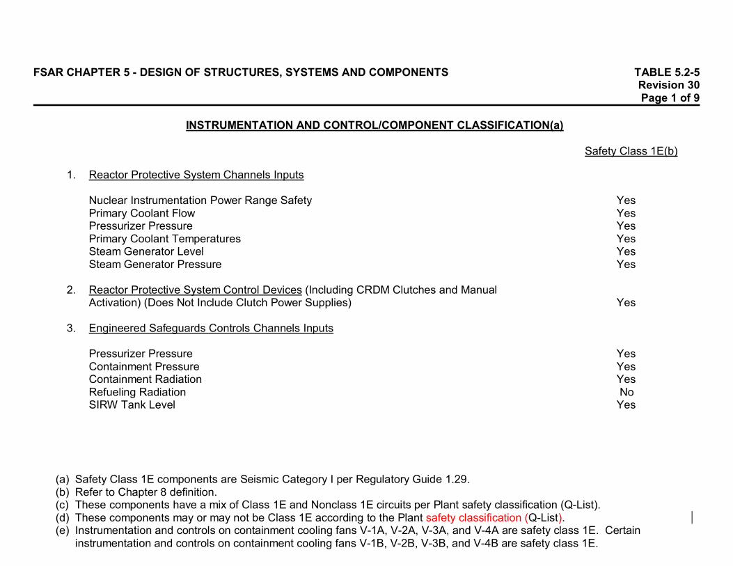
FSAR CHAPTER 5 - DESIGN OF STRUCTURES, SYSTEMS AND COMPONENTS TABLE 5.2-5Revision 30Page 1 of 9
INSTRUMENTATION AND CONTROL/COMPONENT CLASSIFICATION(a)
Safety Class 1E(b)
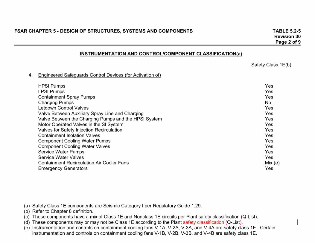
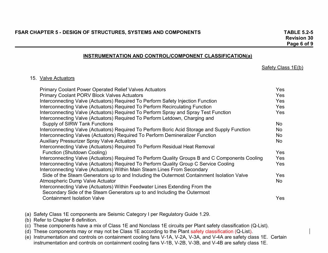
(a) Safety Class 1E components are Seismic Category I per Regulatory Guide 1.29.(b) Refer to Chapter 8 definition.(c) These components have a mix of Class 1E and Nonclass 1E circuits per Plant safety classification (Q-List).(d) These components may or may not be Class 1E according to the Plant safety classification (Q-List).(e) Instrumentation and controls on containment cooling fans V-1A, V-2A, V-3A, and V-4A are safety class 1E. Certain
instrumentation and controls on containment cooling fans V-1B, V-2B, V-3B, and V-4B are safety class 1E.
1. Reactor Protective System Channels Inputs
Nuclear Instrumentation Power Range Safety YesPrimary Coolant Flow YesPressurizer Pressure YesPrimary Coolant Temperatures YesSteam Generator Level YesSteam Generator Pressure Yes
2. Reactor Protective System Control Devices (Including CRDM Clutches and ManualActivation) (Does Not Include Clutch Power Supplies) Yes
3. Engineered Safeguards Controls Channels Inputs
Pressurizer Pressure YesContainment Pressure YesContainment Radiation YesRefueling Radiation NoSIRW Tank Level Yes
FSAR CHAPTER 5 - DESIGN OF STRUCTURES, SYSTEMS AND COMPONENTS TABLE 5.2-5Revision 30Page 2 of 9
INSTRUMENTATION AND CONTROL/COMPONENT CLASSIFICATION(a)
Safety Class 1E(b)
(a) Safety Class 1E components are Seismic Category I per Regulatory Guide 1.29.(b) Refer to Chapter 8 definition.(c) These components have a mix of Class 1E and Nonclass 1E circuits per Plant safety classification (Q-List).(d) These components may or may not be Class 1E according to the Plant safety classification (Q-List).(e) Instrumentation and controls on containment cooling fans V-1A, V-2A, V-3A, and V-4A are safety class 1E. Certain
instrumentation and controls on containment cooling fans V-1B, V-2B, V-3B, and V-4B are safety class 1E.
4. Engineered Safeguards Control Devices (for Activation of)
HPSI Pumps YesLPSI Pumps YesContainment Spray Pumps YesCharging Pumps NoLetdown Control Valves YesValve Between Auxiliary Spray Line and Charging YesValve Between the Charging Pumps and the HPSI System YesMotor Operated Valves in the SI System YesValves for Safety Injection Recirculation YesContainment Isolation Valves YesComponent Cooling Water Pumps YesComponent Cooling Water Valves YesService Water Pumps YesService Water Valves YesContainment Recirculation Air Cooler Fans Mix (e)Emergency Generators Yes

FSAR CHAPTER 5 - DESIGN OF STRUCTURES, SYSTEMS AND COMPONENTS TABLE 5.2-5Revision 30Page 3 of 9
INSTRUMENTATION AND CONTROL/COMPONENT CLASSIFICATION(a)
Safety Class 1E(b)
(a) Safety Class 1E components are Seismic Category I per Regulatory Guide 1.29.(b) Refer to Chapter 8 definition.(c) These components have a mix of Class 1E and Nonclass 1E circuits per Plant safety classification (Q-List).(d) These components may or may not be Class 1E according to the Plant safety classification (Q-List).(e) Instrumentation and controls on containment cooling fans V-1A, V-2A, V-3A, and V-4A are safety class 1E. Certain
instrumentation and controls on containment cooling fans V-1B, V-2B, V-3B, and V-4B are safety class 1E.
5. Engineered Safeguards Controls Instrumentation
HPSI Flow to Primary Coolant System YesSafety Injection Tank Level (Passive Injection) NoSafety Injection Tank Pressure (Passive Injection) NoService Water Break Detectors (in Containment) No
6. Safe Shutdown and Auxiliary Feedwater Instruments Yes
7. Safe Shutdown and Auxiliary Feedwater Control Devices (Activating Circuits)
Power Operated Relief Valves YesShutdown Cooling Isolation Valves YesTurbine-Driven Auxiliary Feedwater Pump YesMotor-Driven Auxiliary Feedwater Pumps YesPressurizer Heaters NoAtmospheric Dump Valves NoAFW Control Valves Yes
8. AFW Automatic Initiation, Isolation and FOGG Control Devices (Including AFWPumps Suction Pressure) Yes

FSAR CHAPTER 5 - DESIGN OF STRUCTURES, SYSTEMS AND COMPONENTS TABLE 5.2-5Revision 30Page 4 of 9
INSTRUMENTATION AND CONTROL/COMPONENT CLASSIFICATION(a)
Safety Class 1E(b)
(a) Safety Class 1E components are Seismic Category I per Regulatory Guide 1.29.(b) Refer to Chapter 8 definition.(c) These components have a mix of Class 1E and Nonclass 1E circuits per Plant safety classification (Q-List).(d) These components may or may not be Class 1E according to the Plant safety classification (Q-List).(e) Instrumentation and controls on containment cooling fans V-1A, V-2A, V-3A, and V-4A are safety class 1E. Certain
instrumentation and controls on containment cooling fans V-1B, V-2B, V-3B, and V-4B are safety class 1E.
9. Primary Coolant Overpressurization Control Devices
Pressurizer Pressure Channels YesPCS Overpressurization Protection Devices YesShutdown Cooling Isolation Valves Controls Yes
10. Reactor Vessel Gas Vent Isolation Valves Controls Yes
11. Engineered Safeguards Pump Rooms and Radwaste Area Radiation Monitors No
12. Control Room Ventilation, Instrumentation and Controls (See Table 9-14) Yes(c)

FSAR CHAPTER 5 - DESIGN OF STRUCTURES, SYSTEMS AND COMPONENTS TABLE 5.2-5Revision 30Page 5 of 9
INSTRUMENTATION AND CONTROL/COMPONENT CLASSIFICATION(a)
Safety Class 1E(b)
(a) Safety Class 1E components are Seismic Category I per Regulatory Guide 1.29.(b) Refer to Chapter 8 definition.(c) These components have a mix of Class 1E and Nonclass 1E circuits per Plant safety classification (Q-List).(d) These components may or may not be Class 1E according to the Plant safety classification (Q-List).(e) Instrumentation and controls on containment cooling fans V-1A, V-2A, V-3A, and V-4A are safety class 1E. Certain
instrumentation and controls on containment cooling fans V-1B, V-2B, V-3B, and V-4B are safety class 1E.
13. Other Safety-Related Display Systems
Subcooled Margin Monitor YesContainment Pressure YesContainment Water Level YesContainment Temperature NoWide-Range Steam Generator Level YesContainment Hydrogen Monitor NoHigh-Range Containment Gamma Radiation Monitor YesReactor Vessel Level Monitoring System YesCore Exit Thermocouples (16 of 43) Yes
14. Local Instrumentation (Refer to Plant Safety Classification (Q-List) for Details)
Transmitters (Inputs to Reactor Protective System) Mix(d)Level, Pressure, etc, Switches (Inputs to Reactor Protective System) Mix(d)Transmitters (Inputs to Engineered Safeguards and Containment Isolation) Mix(d)Level, Pressure, etc, Switches (Inputs to Engineered Safeguards and CI) Mix(d)Transmitters (Inputs to Reactor Shutdown and Decay Heat Removal) Mix(d)Level, Pressure, etc, Switches (Inputs to Reactor Shutdown and DHR) Mix(d)
FSAR CHAPTER 5 - DESIGN OF STRUCTURES, SYSTEMS AND COMPONENTS TABLE 5.2-5Revision 30Page 6 of 9
INSTRUMENTATION AND CONTROL/COMPONENT CLASSIFICATION(a)
Safety Class 1E(b)
(a) Safety Class 1E components are Seismic Category I per Regulatory Guide 1.29.(b) Refer to Chapter 8 definition.(c) These components have a mix of Class 1E and Nonclass 1E circuits per Plant safety classification (Q-List).(d) These components may or may not be Class 1E according to the Plant safety classification (Q-List).(e) Instrumentation and controls on containment cooling fans V-1A, V-2A, V-3A, and V-4A are safety class 1E. Certain
instrumentation and controls on containment cooling fans V-1B, V-2B, V-3B, and V-4B are safety class 1E.
15. Valve Actuators
Primary Coolant Power Operated Relief Valves Actuators YesPrimary Coolant PORV Block Valves Actuators YesInterconnecting Valve (Actuators) Required To Perform Safety Injection Function YesInterconnecting Valve (Actuators) Required To Perform Recirculating Function YesInterconnecting Valve (Actuators) Required To Perform Spray and Spray Test Function YesInterconnecting Valve (Actuators) Required To Perform Letdown, Charging and Supply of SIRW Tank Functions NoInterconnecting Valve (Actuators) Required To Perform Boric Acid Storage and Supply Function NoInterconnecting Valves (Actuators) Required To Perform Demineralizer Function NoAuxiliary Pressurizer Spray Valve Actuators NoInterconnecting Valve (Actuators) Required To Perform Residual Heat Removal Function (Shutdown Cooling) YesInterconnecting Valve (Actuators) Required To Perform Quality Groups B and C Components Cooling YesInterconnecting Valve (Actuators) Required To Perform Quality Group C Service Cooling YesInterconnecting Valve (Actuators) Within Main Steam Lines From Secondary Side of the Steam Generators up to and Including the Outermost Containment Isolation Valve YesAtmospheric Dump Valve Actuator NoInterconnecting Valve (Actuators) Within Feedwater Lines Extending From the Secondary Side of the Steam Generators up to and Including the Outermost Containment Isolation Valve Yes

FSAR CHAPTER 5 - DESIGN OF STRUCTURES, SYSTEMS AND COMPONENTS TABLE 5.2-5Revision 30Page 7 of 9
INSTRUMENTATION AND CONTROL/COMPONENT CLASSIFICATION(a)
Safety Class 1E(b)
(a) Safety Class 1E components are Seismic Category I per Regulatory Guide 1.29.(b) Refer to Chapter 8 definition.(c) These components have a mix of Class 1E and Nonclass 1E circuits per Plant safety classification (Q-List).(d) These components may or may not be Class 1E according to the Plant safety classification (Q-List).(e) Instrumentation and controls on containment cooling fans V-1A, V-2A, V-3A, and V-4A are safety class 1E. Certain
instrumentation and controls on containment cooling fans V-1B, V-2B, V-3B, and V-4B are safety class 1E.
Interconnecting Valve (Actuators) Required To Supply AFW From Condensate Storage Tank to Steam Generators YesInterconnecting Valve (Actuators) Required To Supply Steam From Main Steam System to AFW Turbine-Driven Pump YesInterconnecting Valve (Actuators) That Form an Extension of the Containment Boundary up to and Including the Outermost Containment Isolation Valve for the Containment Purge System YesContainment Cooling Dampers Actuators YesInterconnecting Valves (Actuators) of the Reactor Coolant Pressure Boundary That Penetrate the Containment up to and Including the Outermost Containment Isolation Valve YesInterconnecting Valves (Actuators) of Quality Group B, C or D System That Penetrate the Containment From the First Isolation Valve Inside Con- tainment up to and Including the Outermost Containment Isolation Valve Yes
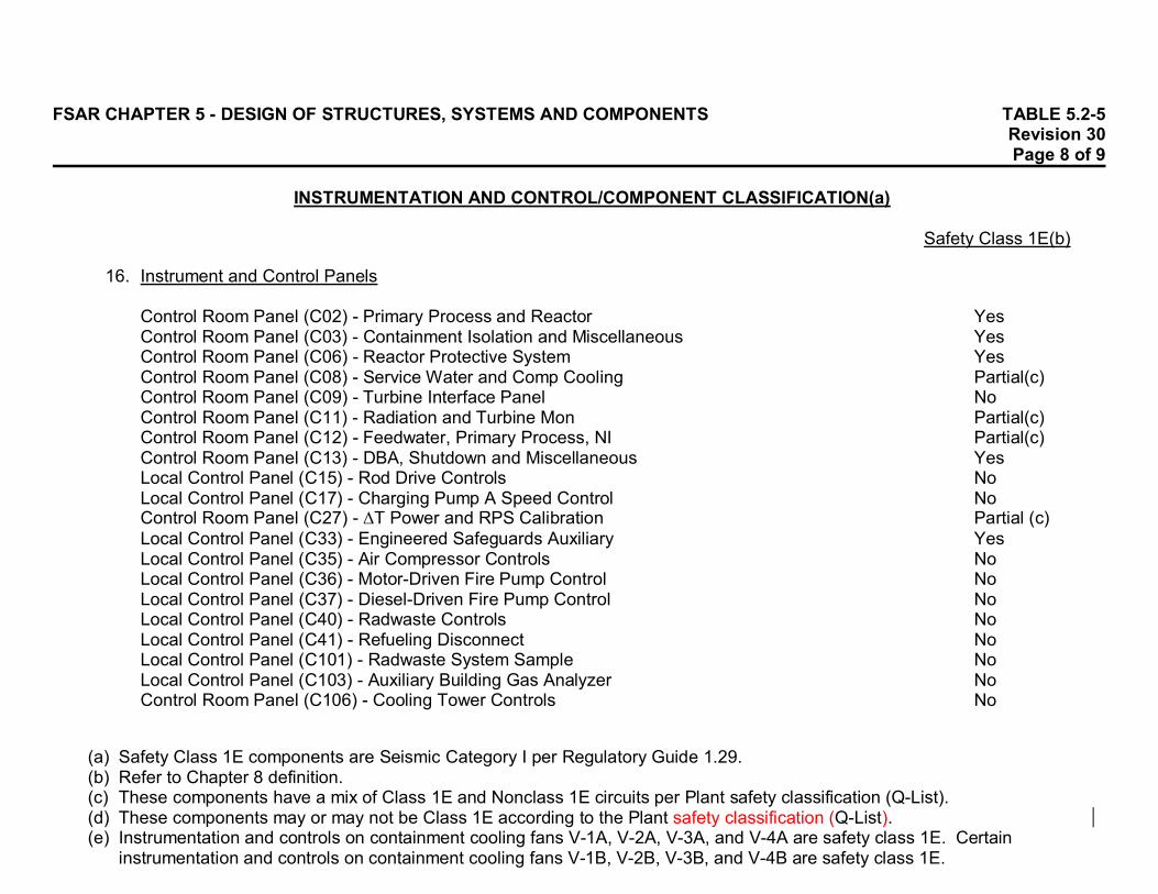
FSAR CHAPTER 5 - DESIGN OF STRUCTURES, SYSTEMS AND COMPONENTS TABLE 5.2-5Revision 30Page 8 of 9
INSTRUMENTATION AND CONTROL/COMPONENT CLASSIFICATION(a)
Safety Class 1E(b)
(a) Safety Class 1E components are Seismic Category I per Regulatory Guide 1.29.(b) Refer to Chapter 8 definition.(c) These components have a mix of Class 1E and Nonclass 1E circuits per Plant safety classification (Q-List).(d) These components may or may not be Class 1E according to the Plant safety classification (Q-List).(e) Instrumentation and controls on containment cooling fans V-1A, V-2A, V-3A, and V-4A are safety class 1E. Certain
instrumentation and controls on containment cooling fans V-1B, V-2B, V-3B, and V-4B are safety class 1E.
16. Instrument and Control Panels
Control Room Panel (C02) - Primary Process and Reactor YesControl Room Panel (C03) - Containment Isolation and Miscellaneous YesControl Room Panel (C06) - Reactor Protective System YesControl Room Panel (C08) - Service Water and Comp Cooling Partial(c)Control Room Panel (C09) - Turbine Interface Panel NoControl Room Panel (C11) - Radiation and Turbine Mon Partial(c)Control Room Panel (C12) - Feedwater, Primary Process, NI Partial(c)Control Room Panel (C13) - DBA, Shutdown and Miscellaneous YesLocal Control Panel (C15) - Rod Drive Controls NoLocal Control Panel (C17) - Charging Pump A Speed Control NoControl Room Panel (C27) - T Power and RPS Calibration Partial (c)Local Control Panel (C33) - Engineered Safeguards Auxiliary YesLocal Control Panel (C35) - Air Compressor Controls NoLocal Control Panel (C36) - Motor-Driven Fire Pump Control NoLocal Control Panel (C37) - Diesel-Driven Fire Pump Control NoLocal Control Panel (C40) - Radwaste Controls NoLocal Control Panel (C41) - Refueling Disconnect NoLocal Control Panel (C101) - Radwaste System Sample NoLocal Control Panel (C103) - Auxiliary Building Gas Analyzer NoControl Room Panel (C106) - Cooling Tower Controls No
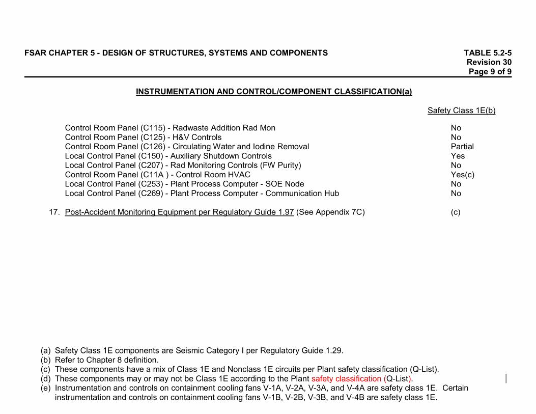
FSAR CHAPTER 5 - DESIGN OF STRUCTURES, SYSTEMS AND COMPONENTS TABLE 5.2-5Revision 30Page 9 of 9
INSTRUMENTATION AND CONTROL/COMPONENT CLASSIFICATION(a)
Safety Class 1E(b)
(a) Safety Class 1E components are Seismic Category I per Regulatory Guide 1.29.(b) Refer to Chapter 8 definition.(c) These components have a mix of Class 1E and Nonclass 1E circuits per Plant safety classification (Q-List).(d) These components may or may not be Class 1E according to the Plant safety classification (Q-List).(e) Instrumentation and controls on containment cooling fans V-1A, V-2A, V-3A, and V-4A are safety class 1E. Certain
instrumentation and controls on containment cooling fans V-1B, V-2B, V-3B, and V-4B are safety class 1E.
Control Room Panel (C115) - Radwaste Addition Rad Mon NoControl Room Panel (C125) - H&V Controls NoControl Room Panel (C126) - Circulating Water and Iodine Removal PartialLocal Control Panel (C150) - Auxiliary Shutdown Controls YesLocal Control Panel (C207) - Rad Monitoring Controls (FW Purity) NoControl Room Panel (C11A ) - Control Room HVAC Yes(c)Local Control Panel (C253) - Plant Process Computer - SOE Node NoLocal Control Panel (C269) - Plant Process Computer - Communication Hub No
17. Post-Accident Monitoring Equipment per Regulatory Guide 1.97 (See Appendix 7C) (c)

FSAR CHAPTER 5 - DESIGN OF STRUCTURES, SYSTEMS AND COMPONENTS TABLE 5.3-1 Revision 21 Page 1 of 1
TORNADO DESIGN PRESSURES
WALL PRESSURE
DESIGN VALUE STRUCTURE DESIGN EQUATION lb/ft2 (psig) Auxiliary Building (Class I 662 (4.6) Portion Except for the Enclosure Over the Spent Fuel Pool) Auxiliary Building Radwaste 600 (4.2) Addition Auxiliary Building 32 (3.0) TSC/EER/HVAC Addition Auxiliary Feedwater Pump Room 432 (3.0)(a) Containment Structure (b) Electrical Penetration Enclosure 432 (3.0) Intake Structure (Class 1 Portion) 432 (3.0)
(a) This room is located below grade. (b) In all cases, seismic loads on the containment structure were larger than their wind or tornado counterparts (missile impact excluded) and since seismic
loads were used in the same or similar load combinations (see Subsections 5.8.3.1.2 and 5.8.3.1.3) as the wind and tornado loads, there was no need to analyze the containment for wind and tornado loads. The resulting containment structure design is inherently resistant to the tornado wind and differential pressure loads.
⎥⎦
⎤⎢⎣
⎡⎟⎠⎞
⎜⎝⎛
ftin 144 psi 3 +
hmi 300
mi fth lb .002558 = P
2
2
2
⎥⎦
⎤⎢⎣
⎡⎟⎠⎞
⎜⎝⎛⎟⎠⎞
⎜⎝⎛
ftin 144 psi 3 +
hmi 300
mi fth lb .002558 .73 = P
2
2
2
⎥⎦
⎤⎢⎣
⎡
ftin 144 psi 3 = P
2
2
⎥⎦
⎤⎢⎣
⎡
ftin 144 psi 3 = P
2
2
⎥⎦
⎤⎢⎣
⎡
ftin 144 psi 3 = P
2
2
⎥⎦
⎤⎢⎣
⎡
ftin 144 psi 3 = P
2
2
⎥⎦
⎤⎢⎣
⎡
ftin 144 psi 3 = P
2
2

FSAR CHAPTER 5 - DESIGN OF STRUCTURES, SYSTEMS AND COMPONENTS TABLE 5.4-1Revision 30Page 1 of 1
SAFETY-RELATED EQUIPMENT THAT REQUIRES PROTECTION FROMFLOODING DUE TO FAILURES OF NONCLASS 1 SYSTEMS
Elevation of Description Location Supporting Floor
Auxiliary Feedwater Pumps Turbine Bldg 571'-0"
Batteries Auxiliary Bldg 607'-6"
Containment Spray Pumps Auxiliary Bldg 570'-0"
Emergency Diesel Generators Auxiliary Bldg 590'-0"
480 V Load Centers Auxiliary Bldg 607'-6"
480 V Motor Control Centers Auxiliary Bldg 607'-6"
Safety Injection Pumps Auxiliary Bldg 570'-0"
Service Water Pumps Intake Structure 590'-0"
2,400 V Switchgear Auxiliary Bldg 607'-6"
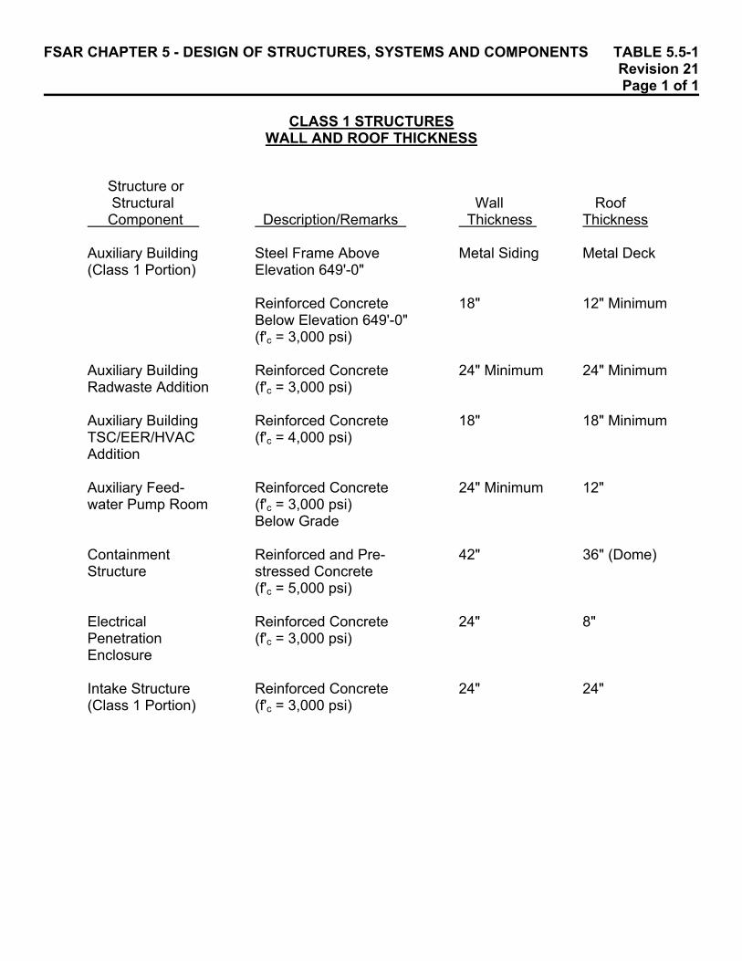
FSAR CHAPTER 5 - DESIGN OF STRUCTURES, SYSTEMS AND COMPONENTS TABLE 5.5-1 Revision 21 Page 1 of 1 CLASS 1 STRUCTURES WALL AND ROOF THICKNESS
Structure or Structural Wall Roof Component Description/Remarks Thickness Thickness Auxiliary Building Steel Frame Above Metal Siding Metal Deck (Class 1 Portion) Elevation 649'-0"
Reinforced Concrete 18" 12" Minimum Below Elevation 649'-0" (f'c = 3,000 psi)
Auxiliary Building Reinforced Concrete 24" Minimum 24" Minimum Radwaste Addition (f'c = 3,000 psi) Auxiliary Building Reinforced Concrete 18" 18" Minimum TSC/EER/HVAC (f'c = 4,000 psi) Addition Auxiliary Feed- Reinforced Concrete 24" Minimum 12" water Pump Room (f'c = 3,000 psi)
Below Grade Containment Reinforced and Pre- 42" 36" (Dome) Structure stressed Concrete
(f'c = 5,000 psi) Electrical Reinforced Concrete 24" 8" Penetration (f'c = 3,000 psi) Enclosure Intake Structure Reinforced Concrete 24" 24" (Class 1 Portion) (f'c = 3,000 psi)

FSAR CHAPTER 5 - DESIGN OF STRUCTURES, SYSTEMS AND COMPONENTS TABLE 5.5-2 Revision 22 Page 1 of 1
BURST PROBABILITY FOR EACH LP ROTOR AND TOTAL UNIT AT 120% RATED SPEED
HOURS
DATE
LP1
LP2
UNIT
ALLOWABLE 12,000
Spring 2001
0.00E+00
0.00E+00
0.00E+00
1.00E-04
24,000
Fall 2002
0.00E+00
0.00E+00
0.00E+00
1.00E-04
36,000
Spring 2004
0.00E+00
0.00E+00
0.00E+00
1.00E-04
48,000
Fall 2005
9.30E-08
0.00E+00
9.30E-08
1.00E-04
60,000
Spring 2007
1.20E-06
4.60E-08
1.25E-06
1.00E-04
72,000
Fall 2008
3.40E-06
7.50E-07
4.15E-06
1.00E-04
84,000
Spring 2010
9.80E-06
2.10E-06
1.19E-05
1.00E-04
96,000
Fall 2011
2.12E-05
6.20E-06
2.74E-05
1.00E-04
108,000
Spring 2013
3.80E-05
1.38E-05
5.18E-05
1.00E-04
120,000
Fall 2014
6.50E-05
2.54E-05
9.04E-05
1.00E-04
132,000
Spring 2016
1.65E-04
3.90E-05
2.04E-04
1.00E-04
144,000
Fall 2017
3.30E-04
6.20E-05
3.92E-04
1.00E-04

FSAR CHAPTER 5 - DESIGN OF STRUCTURES, SYSTEMS AND COMPONENTS TABLE 5.6-1 Revision 21 Page 1 of 2
HIGH-ENERGY PIPE FAILURES OUTSIDE CONTAINMENT - SUMMARY OF OPERATING STRESSES (Calculated 1979-1981)
System: MAIN STEAM (EB-1-36", EB-1-26") Point Pressure Weight Seismic Expansion No Stress, P Stress, W P + W Sh(a) Stress, S P+W+S 1.2Sh(b) Stress, T SA(c) P+W+S+T 0.8(Sh+SA)(d)
(a) Sh = Allowable limit of P + W per applicable code (b) 1.2Sh = Allowable limit of P + W + S per applicable code (c) SA = Allowable limit of T per applicable code (d) 0.8(Sh + SA) = Threshold of stress for mandatory break location in this study, AEC criteria
1 6,459 1,325 7,784 17,500 6,660 14,444 21,000 2,994 26,250 17,438 35,000 2 6,459 3,399 9,858 17,500 3,913 13,771 21,000 6,115 26,250 19,886 35,000 3 6,459 2,992 9,451 17,500 3,865 13,316 21,000 5,336 26,250 18,652 35,000 4 6,459 748 7,207 17,500 3,873 11,080 21,000 3,782 26,250 14,862 35,000 5 6,459 875 7,334 17,500 3,479 10,813 21,000 4,592 26,250 15,405 35,000 6 6,459 1,099 7,558 17,500 3,425 10,983 21,000 2,876 26,250 13,859 35,000 7 8,210 1,111 9,321 17,500 7,261 16,582 21,000 5,903 26,250 22,485 35,000 8 8,210 1,089 9,299 17,500 5,785 15,084 21,000 7,519 26,250 22,063 35,000 9 8,210 321 8,531 17,500 5,831 14,362 21,000 6,754 26,250 21,116 35,000 10 8,210 321 8,531 17,500 5,831 14,362 21,000 6,754 26,250 21,116 35,000 11 8,210 228 8,438 17,500 5,313 13,751 21,000 5,975 26,250 19,726 35,000 12 8,210 1,459 9,669 17,500 5,320 14,989 21,000 6,026 26,250 21,015 35,000 13 8,210 2,557 10,767 17,500 5,481 16,248 21,000 7,084 26,250 23,332 35,000 14 8,210 3,372 11,582 17,500 7,353 18,935 21,000 7,590 26,250 26,525 35,000 15 8,210 3,459 11,669 17,500 9,872 21,541 21,000 9,901 26,250 31,442 35,000 16 5,457 1,016 6,473 17,500 3,372 9,845 21,000 3,450 26,250 13,295 35,000 17 8,210 1,717 9,927 17,500 10,479 20,406 21,000 7,091 26,250 27,497 35,000 18 8,210 941 9,151 17,500 9,567 18,718 21,000 6,602 26,250 25,320 35,000 19 8,210 2,253 10,463 17,500 5,655 16,118 21,000 4,509 26,250 20,627 35,000 20 8,210 3,243 11,453 17,500 5,224 16,677 21,000 3,812 26,250 20,489 35,000 21 8,210 2,973 11,183 17,500 6,520 17,703 21,000 7,886 26,250 25,589 35,000 22 8,210 2,949 11,159 17,500 9,429 20,588 21,000 11,016 26,250 31,604 35,000 23 5,457 912 6,369 17,500 3,333 9,702 21,000 3,600 26,250 13,302 35,000 24 6,459 1,981 8,440 17,500 3,326 11,766 21,000 2,546 26,250 14,312 35,000 25 6,459 4,532 10,991 17,500 3,509 14,500 21,000 4,941 26,250 19,441 35,000 26 6,459 4,872 11,331 17,500 4,020 15,351 21,000 5,561 26,250 20,912 35,000 27 6,459 1,049 7,508 17,500 3,344 10,852 21,000 4,047 26,250 14,899 35,000

FSAR CHAPTER 5 - DESIGN OF STRUCTURES, SYSTEMS AND COMPONENTS TABLE 5.6-1 Revision 21 Page 2 of 2
HIGH-ENERGY PIPE FAILURES OUTSIDE CONTAINMENT - SUMMARY OF OPERATING STRESSES (Calculated 1979-1981)
System: MAIN STEAM (EB-1-36", EB-1-26") Point Pressure Weight Seismic Expansion No Stress, P Stress, W P + W Sh(a) Stress, S P+W+S 1.2Sh(b) Stress, T SA(c) P+W+S+T 0.8(Sh+SA)(d)
(a) Sh = Allowable limit of P + W per applicable code (b) 1.2Sh = Allowable limit of P + W + S per applicable code (c) SA = Allowable limit of T per applicable code (d) 0.8(Sh + SA) = Threshold of stress for mandatory break location in this study, AEC criteria
28 6,459 1,007 7,466 17,500 3,795 11,261 21,000 3,458 26,250 14,719 35,000 29 6,459 883 7,342 17,500 2,309 9,651 21,000 1,133 26,250 10,784 35,000 30 8,212 911 9,123 17,500 4,441 13,564 21,000 6,266 26,250 19,830 35,000 31 8,212 424 8,636 17,500 4,539 13,175 21,000 7,005 26,250 20,180 35,000 32 8,212 424 8,636 17,500 4,539 13,175 21,000 7,005 26,250 20,180 35,000 33 8,212 865 9,077 17,500 4,108 13,185 21,000 6,291 26,250 19,476 35,000 34 8,212 1,591 9,803 17,500 4,641 14,444 21,000 6,807 26,250 21,251 35,000 35 8,212 1,288 9,500 17,500 3,843 13,343 21,000 5,822 26,250 19,165 35,000 36 8,212 1,519 9,731 17,500 5,881 15,612 21,000 2,325 26,250 17,937 35,000 37 8,212 2,472 10,684 17,500 6,373 17,057 21,000 4,403 26,250 21,460 35,000 38 5,457 2,432 7,889 17,500 8,292 16,181 21,000 8,548 26,250 24,729 35,000 39 5,457 1,041 6,498 17,500 4,305 10,803 21,000 4,320 26,250 15,123 35,000 40 8,212 1,124 9,336 17,500 7,476 16,812 21,000 4,519 26,250 21,331 35,000 41 8,212 623 8,835 17,500 6,816 15,651 21,000 3,976 26,250 19,627 35,000 42 8,212 2,765 10,977 17,500 4,968 15,945 21,000 1,736 26,250 17,681 35,000 43 8,212 2,321 10,533 17,500 3,995 14,528 21,000 1,621 26,250 16,149 35,000 44 8,212 809 9,021 17,500 3,299 12,320 21,000 2,609 26,250 14,929 35,000 45 8,212 1,476 9,688 17,500 4,605 14,293 21,000 3,899 26,250 18,192 35,000 46 5,457 3,223 11,435 17,500 8,136 24,212 21,000 5,555 26,250 29,767 35,000 47 5,457 1,469 9,681 17,500 3,982 13,663 21,000 2,687 26,250 16,350 35,000

FSAR CHAPTER 5 - DESIGN OF STRUCTURES, SYSTEMS AND COMPONENTS TABLE 5.6-2 Revision 21 Page 1 of 5
HIGH-ENERGY PIPE FAILURES OUTSIDE CONTAINMENT - SUMMARY OF OPERATING STRESSES (Calculated 1979-1981)
System: FEEDWATER (DB-1-18" and EB-9-18", DB-1-12") Point Pressure Weight Seismic Expansion No Stress, P Stress, W P + W Sh(a) Stress, S P+W+S 1.2Sh(b) Stress, T SA(c) P+W+S+T 0.8(Sh+SA)(d)
(a) Sh = Allowable limit of P + W per applicable code (b) 1.2Sh = Allowable limit of P + W + S per applicable code (c) SA = Allowable limit of T per applicable code (d) 0.8(Sh + SA) = Threshold of stress for mandatory break location in this study, AEC criteria
1 5,787 247 6,034 15,000 3,194 9,228 18,000 6,123 22,500 15,351 30,000 2 5,787 125 5,912 15,000 710 6,622 18,000 801 22,500 7,423 30,000 3 5,787 250 6,037 15,000 172 6,209 18,000 493 22,500 6,702 30,000 4 5,787 280 6,067 15,000 2,215 8,282 18,000 10,523 22,500 18,805 30,000 5 5,787 769 6,556 15,000 2,585 9,141 18,000 10,893 22,500 20,034 30,000 6 5,787 516 6,303 15,000 1,800 8,103 18,000 10,191 22,500 18,294 30,000 7 5,787 740 6,527 15,000 1,533 8,060 18,000 8,385 22,500 16,445 30,000 8 5,787 571 6,358 15,000 1,648 8,006 18,000 4,182 22,500 12,188 30,000 9 5,787 337 6,124 15,000 2,072 8,196 18,000 3,123 22,500 11,319 30,000 10 5,787 273 6,060 15,000 2,171 8,231 18,000 4,060 22,500 12,291 30,000 11 5,787 25 5,812 15,000 1,937 7,749 18,000 2,733 22,500 10,482 30,000 12 5,787 567 6,354 15,000 1,924 8,278 18,000 1,508 22,500 9,786 30,000 13 5,787 1,065 6,852 15,000 3,683 10,535 18,000 6,841 22,500 17,376 30,000 14 5,787 745 6,532 15,000 2,907 9,439 18,000 5,112 22,500 14,551 30,000 15 - - - - - - - - - - - 16 5,787 377 6,164 15,000 1,844 8,008 18,000 3,222 22,500 11,230 30,000 17 5,896 903 6,690 15,000 2,011 8,701 18,000 2,604 22,500 11,305 30,000 18 5,896 1,009 6,905 15,000 3,423 10,328 18,000 2,154 22,500 12,482 30,000 19 5,896 302 6,198 15,000 1,115 7,313 18,000 641 22,500 7,954 30,000 20 5,896 218 6,114 15,000 1,013 7,127 18,000 856 22,500 7,983 30,000 21 5,787 773 6,560 15,000 3,255 9,815 18,000 842 22,500 10,657 30,000 22 5,787 632 6,419 15,000 2,278 8,697 18,000 2,323 22,500 11,020 30,000 23 5,787 387 6,174 15,000 3,880 10,054 18,000 3,950 22,500 14,004 30,000 24 5,787 126 5,913 15,000 1,897 7,810 18,000 1,682 22,500 9,492 30,000 25 5,991 487 6,478 15,000 3,512 9,990 18,000 2,516 22,500 12,506 30,000 26 5,991 345 6,336 15,000 1,713 8,049 18,000 806 22,500 8,855 30,000 27 5,787 1,395 7,182 15,000 5,165 12,347 18,000 4,477 22,500 16,824 30,000

FSAR CHAPTER 5 - DESIGN OF STRUCTURES, SYSTEMS AND COMPONENTS TABLE 5.6-2 Revision 21 Page 2 of 5
HIGH-ENERGY PIPE FAILURES OUTSIDE CONTAINMENT - SUMMARY OF OPERATING STRESSES (Calculated 1979-1981)
System: FEEDWATER (DB-1-18" and EB-9-18", DB-1-12") Point Pressure Weight Seismic Expansion No Stress, P Stress, W P + W Sh(a) Stress, S P+W+S 1.2Sh(b) Stress, T SA(c) P+W+S+T 0.8(Sh+SA)(d)
(a) Sh = Allowable limit of P + W per applicable code (b) 1.2Sh = Allowable limit of P + W + S per applicable code (c) SA = Allowable limit of T per applicable code (d) 0.8(Sh + SA) = Threshold of stress for mandatory break location in this study, AEC criteria
28 5,787 1,459 7,246 15,000 3,960 11,206 18,000 3,272 22,500 14,478 30,000 29 5,787 1,375 7,162 15,000 3,828 10,990 18,000 2,651 22,500 13,641 30,000 30 5,787 1,056 6,843 15,000 3,892 10,735 18,000 2,114 22,500 12,849 30,000 30A 5,787 1,087 6,874 15,000 1,490 8,364 18,000 1,364 22,500 9,728 30,000 31 5,787 1,167 6,954 15,000 3,208 10,162 18,000 3,952 22,500 14,114 30,000 32 5,787 808 6,595 15,000 3,195 9,790 18,000 4,756 22,500 14,546 30,000 32A 5,787 759 6,546 15,000 3,893 10,439 18,000 4,900 22,500 15,339 30,000 33 5,787 644 6,431 15,000 4,465 10,896 18,000 5,783 22,500 16,679 30,000 34 5,787 557 6,344 15,000 4,720 11,064 18,000 4,995 22,500 16,059 30,000 34A 5,787 1,132 6,919 15,000 6,663 13,582 18,000 6,399 22,500 19,981 30,000 35 5,787 2,401 8,188 15,000 7,345 15,533 18,000 7,898 22,500 23,431 30,000 36 4,587 490 5,077 15,000 1,635 6,712 18,000 1,458 22,500 8,170 30,000 37 4,587 855 5,442 15,000 3,660 9,102 18,000 2,679 22,500 11,781 30,000 38 5,680 1,128 6,808 15,000 3,695 10,503 18,000 3,695 22,500 14,198 30,000 39 5,680 1,170 6,850 15,000 4,244 11,094 18,000 5,916 22,500 17,010 30,000 40 5,680 3,843 9,523 15,000 8,123 17,646 18,000 10,622 22,500 28,268 30,000 41 4,587 858 5,445 15,000 2,616 8,061 18,000 4,114 22,500 12,175 30,000 42 4,587 632 5,219 15,000 3,468 8,687 18,000 4,325 22,500 13,012 30,000 43 4,587 613 5,200 15,000 3,603 8,803 18,000 4,317 22,500 13,120 30,000 44 4,587 391 4,978 15,000 1,942 6,920 18,000 2,264 22,500 9,184 30,000 45 4,587 69 4,656 15,000 3,812 8,468 18,000 5,780 22,500 14,248 30,000 46 5,699 1,382 7,081 15,000 10,205 17,286 18,000 10,760 22,500 28,046 30,000 47 5,680 888 6,568 15,000 5,104 11,672 18,000 2,961 22,500 14,633 30,000 48 5,680 768 6,448 15,000 4,187 10,635 18,000 2,018 22,500 12,653 30,000 49 5,680 785 6,465 15,000 5,393 11,858 18,000 2,376 22,500 14,234 30,000 50 5,680 509 6,189 15,000 5,396 11,585 18,000 2,861 22,500 14,446 30,000 51 5,680 220 5,900 15,000 4,398 10,289 18,000 2,712 22,500 13,001 30,000

FSAR CHAPTER 5 - DESIGN OF STRUCTURES, SYSTEMS AND COMPONENTS TABLE 5.6-2 Revision 21 Page 3 of 5
HIGH-ENERGY PIPE FAILURES OUTSIDE CONTAINMENT - SUMMARY OF OPERATING STRESSES (Calculated 1979-1981)
System: FEEDWATER (DB-1-18" and EB-9-18", DB-1-12") Point Pressure Weight Seismic Expansion No Stress, P Stress, W P + W Sh(a) Stress, S P+W+S 1.2Sh(b) Stress, T SA(c) P+W+S+T 0.8(Sh+SA)(d)
(a) Sh = Allowable limit of P + W per applicable code (b) 1.2Sh = Allowable limit of P + W + S per applicable code (c) SA = Allowable limit of T per applicable code (d) 0.8(Sh + SA) = Threshold of stress for mandatory break location in this study, AEC criteria
52 5,680 795 6,475 15,000 5,074 11,549 18,000 1,037 22,500 12,586 30,000 53 5,680 188 5,868 15,000 6,155 12,023 18,000 1,695 22,500 13,718 30,000 54 5,680 196 5,876 15,000 6,872 12,748 18,000 1,224 22,500 13,972 30,000 55 5,680 140 5,820 15,000 6,380 12,200 18,000 337 22,500 12,537 30,000 56 5,680 212 5,892 15,000 9,705 15,597 18,000 3,310 22,500 18,907 30,000 57 5,680 401 6,081 15,000 9,248 15,329 18,000 3,919 22,500 19,248 30,000 58 5,680 549 6,229 15,000 4,916 11,145 18,000 3,503 22,500 14,648 30,000 59 5,680 509 6,189 15,000 9,023 15,212 18,000 2,723 22,500 17,935 30,000 60 5,680 348 6,028 15,000 6,801 12,829 18,000 3,815 22,500 16,644 30,000 61 5,680 271 5,951 15,000 7,357 13,308 18,000 4,333 22,500 17,641 30,000 62 - - - - - - - - - - - 63 5,680 472 6,152 15,000 8,015 14,167 18,000 6,236 22,500 20,403 30,000 64 5,680 162 5,842 15,000 4,259 10,101 18,000 3,078 22,500 13,179 30,000 65 4,587 124 4,711 15,000 1,119 5,830 18,000 1,218 22,500 7,048 30,000 66 4,587 268 4,855 15,000 3,949 8,804 18,000 1,967 22,500 10,771 30,000 67 5,699 1,475 7,174 15,000 8,302 15,476 18,000 4,386 22,500 19,862 30,000 68 5,680 538 6,218 15,000 3,774 9,992 18,000 3,947 22,500 13,939 30,000 69 5,680 333 6,013 15,000 1,865 7,878 18,000 2,020 22,500 9,898 30,000 70 5,680 332 6,012 15,000 1,765 7,777 18,000 1,516 22,500 9,293 30,000 71 4,587 2,077 6,664 15,000 5,363 12,027 18,000 2,171 22,500 14,198 30,000 72 4,587 683 5,270 15,000 930 6,200 18,000 679 22,500 6,879 30,000 73 5,787 441 6,228 15,000 147 6,375 18,000 535 22,500 6,910 30,000 74 5,787 1,293 7,080 15,000 5,111 12,191 18,000 4,914 22,500 17,105 30,000 75 5,787 1,103 6,890 15,000 5,624 12,514 18,000 5,308 22,500 17,822 30,000 76 5,787 399 6,186 15,000 3,012 9,198 18,000 3,525 22,500 12,723 30,000 77 5,787 665 6,452 15,000 3,041 9,493 18,000 4,577 22,500 14,070 30,000 78 5,787 620 6,407 15,000 2,840 9,247 18,000 4,693 22,500 13,940 30,000
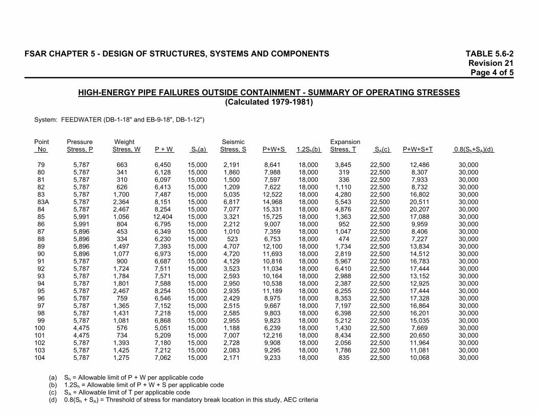
FSAR CHAPTER 5 - DESIGN OF STRUCTURES, SYSTEMS AND COMPONENTS TABLE 5.6-2 Revision 21 Page 4 of 5
HIGH-ENERGY PIPE FAILURES OUTSIDE CONTAINMENT - SUMMARY OF OPERATING STRESSES (Calculated 1979-1981)
System: FEEDWATER (DB-1-18" and EB-9-18", DB-1-12") Point Pressure Weight Seismic Expansion No Stress, P Stress, W P + W Sh(a) Stress, S P+W+S 1.2Sh(b) Stress, T SA(c) P+W+S+T 0.8(Sh+SA)(d)
(a) Sh = Allowable limit of P + W per applicable code (b) 1.2Sh = Allowable limit of P + W + S per applicable code (c) SA = Allowable limit of T per applicable code (d) 0.8(Sh + SA) = Threshold of stress for mandatory break location in this study, AEC criteria
79 5,787 663 6,450 15,000 2,191 8,641 18,000 3,845 22,500 12,486 30,000 80 5,787 341 6,128 15,000 1,860 7,988 18,000 319 22,500 8,307 30,000 81 5,787 310 6,097 15,000 1,500 7,597 18,000 336 22,500 7,933 30,000 82 5,787 626 6,413 15,000 1,209 7,622 18,000 1,110 22,500 8,732 30,000 83 5,787 1,700 7,487 15,000 5,035 12,522 18,000 4,280 22,500 16,802 30,000 83A 5,787 2,364 8,151 15,000 6,817 14,968 18,000 5,543 22,500 20,511 30,000 84 5,787 2,467 8,254 15,000 7,077 15,331 18,000 4,876 22,500 20,207 30,000 85 5,991 1,056 12,404 15,000 3,321 15,725 18,000 1,363 22,500 17,088 30,000 86 5,991 804 6,795 15,000 2,212 9,007 18,000 952 22,500 9,959 30,000 87 5,896 453 6,349 15,000 1,010 7,359 18,000 1,047 22,500 8,406 30,000 88 5,896 334 6,230 15,000 523 6,753 18,000 474 22,500 7,227 30,000 89 5,896 1,497 7,393 15,000 4,707 12,100 18,000 1,734 22,500 13,834 30,000 90 5,896 1,077 6,973 15,000 4,720 11,693 18,000 2,819 22,500 14,512 30,000 91 5,787 900 6,687 15,000 4,129 10,816 18,000 5,967 22,500 16,783 30,000 92 5,787 1,724 7,511 15,000 3,523 11,034 18,000 6,410 22,500 17,444 30,000 93 5,787 1,784 7,571 15,000 2,593 10,164 18,000 2,988 22,500 13,152 30,000 94 5,787 1,801 7,588 15,000 2,950 10,538 18,000 2,387 22,500 12,925 30,000 95 5,787 2,467 8,254 15,000 2,935 11,189 18,000 6,255 22,500 17,444 30,000 96 5,787 759 6,546 15,000 2,429 8,975 18,000 8,353 22,500 17,328 30,000 97 5,787 1,365 7,152 15,000 2,515 9,667 18,000 7,197 22,500 16,864 30,000 98 5,787 1,431 7,218 15,000 2,585 9,803 18,000 6,398 22,500 16,201 30,000 99 5,787 1,081 6,868 15,000 2,955 9,823 18,000 5,212 22,500 15,035 30,000
100 4,475 576 5,051 15,000 1,188 6,239 18,000 1,430 22,500 7,669 30,000 101 4,475 734 5,209 15,000 7,007 12,216 18,000 8,434 22,500 20,650 30,000 102 5,787 1,393 7,180 15,000 2,728 9,908 18,000 2,056 22,500 11,964 30,000 103 5,787 1,425 7,212 15,000 2,083 9,295 18,000 1,786 22,500 11,081 30,000 104 5,787 1,275 7,062 15,000 2,171 9,233 18,000 835 22,500 10,068 30,000
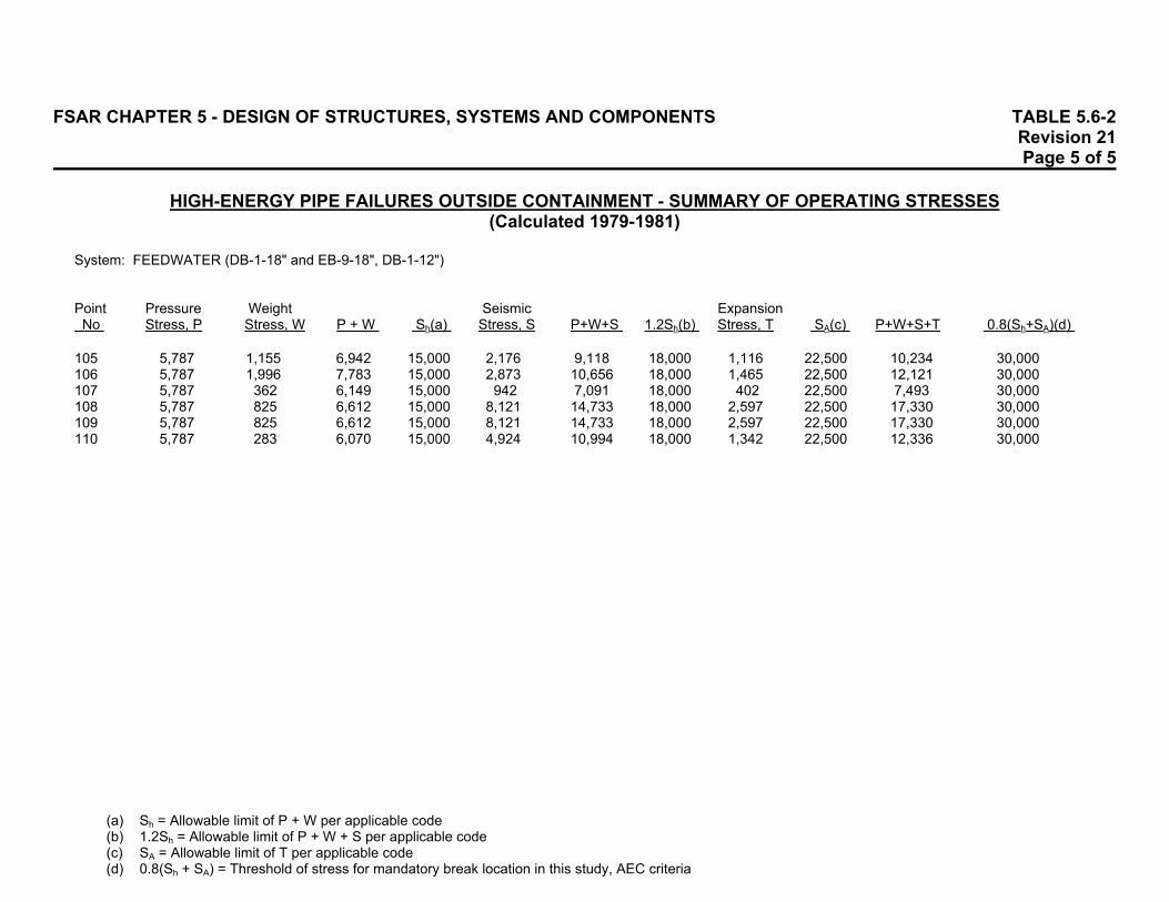
FSAR CHAPTER 5 - DESIGN OF STRUCTURES, SYSTEMS AND COMPONENTS TABLE 5.6-2 Revision 21 Page 5 of 5
HIGH-ENERGY PIPE FAILURES OUTSIDE CONTAINMENT - SUMMARY OF OPERATING STRESSES (Calculated 1979-1981)
System: FEEDWATER (DB-1-18" and EB-9-18", DB-1-12") Point Pressure Weight Seismic Expansion No Stress, P Stress, W P + W Sh(a) Stress, S P+W+S 1.2Sh(b) Stress, T SA(c) P+W+S+T 0.8(Sh+SA)(d)
(a) Sh = Allowable limit of P + W per applicable code (b) 1.2Sh = Allowable limit of P + W + S per applicable code (c) SA = Allowable limit of T per applicable code (d) 0.8(Sh + SA) = Threshold of stress for mandatory break location in this study, AEC criteria
105 5,787 1,155 6,942 15,000 2,176 9,118 18,000 1,116 22,500 10,234 30,000 106 5,787 1,996 7,783 15,000 2,873 10,656 18,000 1,465 22,500 12,121 30,000 107 5,787 362 6,149 15,000 942 7,091 18,000 402 22,500 7,493 30,000 108 5,787 825 6,612 15,000 8,121 14,733 18,000 2,597 22,500 17,330 30,000 109 5,787 825 6,612 15,000 8,121 14,733 18,000 2,597 22,500 17,330 30,000 110 5,787 283 6,070 15,000 4,924 10,994 18,000 1,342 22,500 12,336 30,000

FSAR CHAPTER 5 - DESIGN OF STRUCTURES, SYSTEMS AND COMPONENTS TABLE 5.6-3 Revision 21 Page 1 of 1
HIGH-ENERGY PIPE FAILURES OUTSIDE CONTAINMENT - SUMMARY OF OPERATING STRESSES
(Calculated 1979-1981) System: MAIN STEAM DUMP (EB-1-8", GB-19-8") Point Pressure Weight Seismic Expansion No Stress, P Stress, W P + W Sh(a) Stress, S P+W+S 1.2Sh(b) Stress, T SA(c) P+W+S+T 0.8(Sh+SA)(d) 1 2,680 9 2,689 15,000 1,639 4,328 18,000 833 22,500 5,161 30,000 2 2,680 927 3,607 15,000 2,110 5,717 18,000 1,130 22,500 6,847 30,000 3 5,956 225 6,181 15,000 1,091 7,272 18,000 2,610 22,500 9,882 30,000 4 5,956 1,577 7,533 15,000 2,377 9,910 18,000 5,397 22,500 15,307 30,000 5 5,956 932 6,888 15,000 1,113 8,001 18,000 15,565 22,500 23,566 30,000 6 5,956 1,204 7,160 15,000 1,159 8,319 18,000 15,559 22,500 23,878 30,000 7 5,956 1,705 7,661 15,000 1,679 9,340 18,000 9,157 22,500 18,497 30,000 8 5,956 1,868 7,824 15,000 1,784 9,608 18,000 9,687 22,500 28,009 30,000 9 5,956 1,857 7,813 15,000 1,848 9,661 18,000 13,441 22,500 30,702 30,000 (a) Sh = Allowable limit of P + W per applicable code (b) 1.2Sh = Allowable limit of P + W + S per applicable code (c) SA = Allowable limit of T per applicable code (d) 0.8(Sh + SA) = Threshold of stress for mandatory break location in this study, AEC criteria
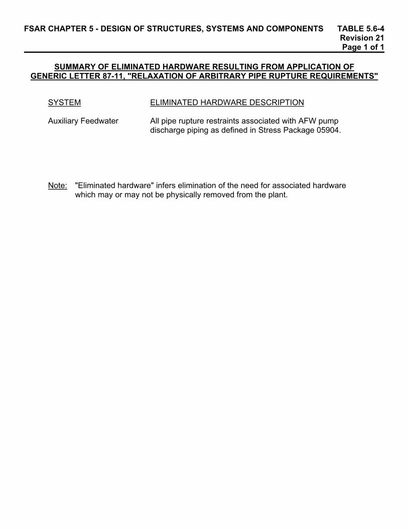
FSAR CHAPTER 5 - DESIGN OF STRUCTURES, SYSTEMS AND COMPONENTS TABLE 5.6-4 Revision 21 Page 1 of 1 SUMMARY OF ELIMINATED HARDWARE RESULTING FROM APPLICATION OF GENERIC LETTER 87-11, "RELAXATION OF ARBITRARY PIPE RUPTURE REQUIREMENTS"
SYSTEM ELIMINATED HARDWARE DESCRIPTION Auxiliary Feedwater All pipe rupture restraints associated with AFW pump
discharge piping as defined in Stress Package 05904. Note: "Eliminated hardware" infers elimination of the need for associated hardware
which may or may not be physically removed from the plant.

FSAR CHAPTER 5 - DESIGN OF STRUCTURES, SYSTEMS AND COMPONENTS TABLE 5.7-1 Revision 21 Page 1 of 1
LIST OF COMPUTER CODES
Bechtel Code Reference Number Name Original Source Description Section CE611 Time Loading Bechtel Time History Response Analysis 5.7.1.3 CE802 SPECTRA Bechtel Floor Response Spectra 5.7.1.3 CE800 BSAP UC Berkeley Static and Dynamic Structural Analysis 5.7.1.3, 5.7.3.4 CE309 Stress MIT Linear Stress Analysis 5.7.2 CE617 Diagonalization Bechtel Mode Shapes and Frequencies 5.7.2 CE641 - Bechtel Response Spectrum Analysis 5.7.2 CE207 DAMPSI Bechtel Composite Modal Damping 5.7.3.4 CE201 BSAP-POST Bechtel Plot Mode Shapes, etc 5.7.3.4 CE705 - Bechtel Beam on Elastic Foundation 5.7.3.4 - PISOL EDS Nuclear Piping Analysis 5.7.4 ME632(a) Piping Bechtel Piping Analysis 5.7.4 ME101 Piping Bechtel Piping Analysis 5.7.4 - MEC-21 Mare Island
Naval Shipyard Unknown 5.7.5.1 CE991 STARDYNE Mechanics Research Static and Dynamic Structural Analysis 5.7.6 CE798 ANSYS Swanson Analysis Nonlinear Analysis 5.7.6
(a) ME101 replaces ME632.

FSAR CHAPTER 5 - DESIGN OF STRUCTURES, SYSTEMS AND COMPONENTS TABLE 5.7-2 Revision 21 Page 1 of 1 MATERIAL DAMPING VALUES FOR VARIOUS MATERIALS AND TYPES OF CONSTRUCTION
(a) For reevaluations and modifications reviewed after July 1986, the damping values
from ASME Code Case N-411, Figure 1, will be used. (b) Material damping for TSC/EER analysis only.
% of Critical Damping OBE SSE
Welded Steel Plate Assemblies 1.0 1.0 Welded Steel Frame Assemblies 2.0 2.0 Bolted Steel Frame Assemblies 2.0 2.0 Concrete Equipment Supports on Another Structure 2.0 2.0 Steel Piping(a) 0.5 0.5 Soil(b) 3.0 3.0

FSAR CHAPTER 5 - DESIGN OF STRUCTURES, SYSTEMS AND COMPONENTS TABLE 5.7-3 Revision 23 Page 1 of 1 MATERIAL DAMPING VALUES FOR VARIOUS CLASS 1 STRUCTURES
% of Critical Damping OBE SSE
Containment Building (Posttensioned and Reinforced Concrete) 2.0 5.0 Auxiliary Building (Reinforced Concrete) 2.0 (a) Auxiliary Building (Steel Framing) 0.5(c) (a) Auxiliary Building Radwaste Addition (Reinforced Concrete) 5.0 (a) Auxiliary Building TSC/EER Addition (Reinforced Concrete) 5.0 (a) Electrical Penetration Enclosure (Reinforced Concrete) 5.0 (a) Soil (Rocking and Swaying) for Containment Building(b) 5.0 10.0 Soil (Rocking and Swaying) for Auxiliary Building(b) 5.0 (a) Spent Fuel Storage Racks 4.0 4.0 (a) No SSE analysis was performed. (b) Radiation damping. (c) For purposes of employing composite damping in the overall building structural
model only.

FSAR CHAPTER 5 - DESIGN OF STRUCTURES, SYSTEMS AND COMPONENTS TABLE 5.7-4 Revision 21 Page 1 of 1 AUXILIARY BUILDING TSC/EER ADDITION SUMMARY OF MODAL PARAMETERS FLEXIBLE BASE ANALYSIS
TORSIONAL STIFFNESS BASED ON INDIVIDUAL WALL SECTIONS
Frequency Damping Participation Factors Mode (Hz) (%) North-South East-West Vertical 1 1.29 4.7 -0.223 -4.607 0.032 2 3.58 5.0 -0.776 -0.517 0.025 3 4.27 5.2 -8.565 1.684 0.392 4 4.61 6.4 1.393 7.421 -0.645 5 6.57 5.4 -1.797 -1.573 -0.345 6 9.27 10.0 -0.858 -0.653 -10.557 7 13.90 10.0 -5.826 0.076 0.777 8 15.04 10.0 -0.049 5.618 -0.373 9 20.38 10.0 0.039 -0.439 -0.069 10 23.86 10.0 -0.310 0.061 -1.084 TORSIONAL STIFFNESS BASED ON WALLS ACTING TOGETHER
Frequency Damping Participation Factors Mode (Hz) (%) North-South East-West Vertical 1 3.45 4.1 0.405 -8.529 0.358 2 4.38 5.4 8.873 0.415 -0.557 3 7.22 5.7 0.545 -1.256 0.240 4 9.27 10.0 -0.838 -0.525 -10.568 5 12.54 10.0 -0.071 -5.525 0.252 6 13.90 10.0 -5.827 0.024 0.778 7 17.85 10.0 0.064 -2.893 0.174 8 22.14 10.0 0.066 -0.633 -0.086 9 23.83 10.0 0.308 -0.160 1.075 10 25.99 6.5 0.074 0.220 0.139 NOTE: Participation factors for significant modes are underlined.
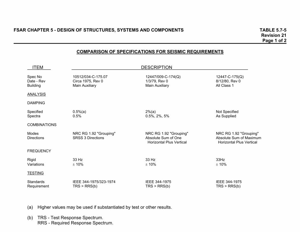
FSAR CHAPTER 5 - DESIGN OF STRUCTURES, SYSTEMS AND COMPONENTS TABLE 5.7-5 Revision 21 Page 1 of 2 COMPARISON OF SPECIFICATIONS FOR SEISMIC REQUIREMENTS
ITEM DESCRIPTION
(a) Higher values may be used if substantiated by test or other results. (b) TRS - Test Response Spectrum.
RRS - Required Response Spectrum.
Spec No 10512/034-C-175.07 12447/009-C-174(Q) 12447-C-175(Q) Date - Rev Circa 1975, Rev 0 1/3/79, Rev 0 8/12/80, Rev 0 Building Main Auxiliary Main Auxiliary All Class 1 ANALYSIS DAMPING Specified 0.5%(a) 2%(a) Not Specified Spectra 0.5% 0.5%, 2%, 5% As Supplied COMBINATIONS Modes NRC RG 1.92 "Grouping" NRC RG 1.92 "Grouping" NRC RG 1.92 "Grouping" Directions SRSS 3 Directions Absolute Sum of One Absolute Sum of Maximum
Horizontal Plus Vertical Horizontal Plus Vertical FREQUENCY Rigid 33 Hz 33 Hz 33Hz Variations ± 10% ± 10% ± 10% TESTING Standards IEEE 344-1975/323-1974 IEEE 344-1975 IEEE 344-1975 Requirement TRS > RRS(b) TRS > RRS(b) TRS > RRS(b)

FSAR CHAPTER 5 - DESIGN OF STRUCTURES, SYSTEMS AND COMPONENTS TABLE 5.7-5 Revision 21 Page 2 of 2 COMPARISON OF SPECIFICATIONS FOR SEISMIC REQUIREMENTS
ITEM DESCRIPTION
(a) Higher values may be used if substantiated by test or other results. (b) TRS - Test Response Spectrum.
RRS - Required Response Spectrum.
MOTION Type Single or Multiple Single or Multiple Single (With Permission)
Frequency as Appropriate Frequency or Multiple Frequency Directions Uniaxial, Biaxial, Biaxial for Each Biaxial for Each
Triaxial Horizontal Direction Horizontal Direction Frequency Not Specified 1-40 Hz 1-40 Hz Duration 20 Seconds 30 Seconds 30 Seconds TEST TYPE Not Specified Proof or Fragility Proof or Fragility Spec No 10512/034-C-175.07 1244/009-C-174(Q) 12447-C-175(Q) COMBINED TESTING AND ANALYSIS IEEE 344-1975 Not Specified IEEE 344-1975 OTHER CONSIDERATIONS Time History Analysis, Multiple Supports - Use
Nonlinear Systems, Envelope of Spectra Multiple Equipment Plus Support Movements Frequencies Under Widened Spectrum Peak (Section 5.3.1 of BC-TOP-4-A), Certification of Results by PE

FSAR CHAPTER 5 - DESIGN OF STRUCTURES, SYSTEMS AND COMPONENTS TABLE 5.7-6 Revision 21 Page 1 of 2 MAJOR CLASS 1 COMPONENTS SEISMIC LOADS (g)
Specification Values
System Component OBE SSE Direction Auxiliary Auxiliary Feed Pumps 0.10 g 0.20 g Horizontal Feedwater 0.067 g 0.14 g Vertical Component Component Cooling 0.121 g 0.23 g Horizontal Cooling Heat Exchangers 0.067 g 0.14 g Vertical
Component Cooling 0.121 g 0.229 g Horizontal Pumps 0.067 g 0.133 g Vertical
Component Cooling 0.16 g 0.30 g Horizontal Water Surge Tank (T-3) 0.07 g 0.14 g Vertical
Containment Containment Spray 0.10 g 0.20 g Horizontal Spray Pumps 0.067 g 0.14 g Vertical
Shutdown Cooling Heat - 0.7 g Horizontal Exchangers - 0.47 g Vertical
Emergency Diesels 0.121 g 0.230 g Horizontal Diesel Generator 0.067 g 0.133 g Vertical
Generators 0.121 g 0.230 g Horizontal (Class 1E) 0.067 g 0.133 g Vertical
Safety Injection Containment Safety 0.9 g 1.5 g Horizontal
Injection Tanks 0.1 g 0.2 g Vertical (T-82A, T-82B, T-82C, T-82D)
High- and Low-Pressure - 0.35 g Horizontal Safety Injection Pumps - 0.24 g Vertical
Safety Injection and 0.23 g 0.42 g Horizontal Refueling Water Tank 0.07 g 0.133 g Vertical (T-58)
Service Water Service Water Pumps 0.46 g 0.90 g Horizontal
0.07 g 0.14 g Vertical Shield Cooling Shield Coolant Surge 0.16 g 0.30 g Horizontal
Tank (T-62) 0.07 g 0.14 g Vertical

FSAR CHAPTER 5 - DESIGN OF STRUCTURES, SYSTEMS AND COMPONENTS TABLE 5.7-6 Revision 21 Page 2 of 2 MAJOR CLASS 1 COMPONENTS SEISMIC LOADS (g)
Specification Values
System Component OBE SSE Direction Spent Fuel Pool Fuel Pool 0.121 g 0.230 g Horizontal
Demineralizer 0.067 g 0.133 g Vertical (Mixed Bed)
Fuel Pool Filter 0.121 g 0.230 g Horizontal
0.067 g 0.133 g Vertical
Fuel Pool Cooling Heat 0.121 g 0.23 g Horizontal Exchangers 0.067 g 0.14 g Vertical
NOTE: This is a list of the seismic requirements for various CP Co Design Class 1 components as described in the components' specifications. Since these specifications were written, Palisades has upgraded its seismic methodologies to reflect industry standards. These upgraded seismic methodologies are described in Specification C -175, "Requirements for Seismic Evaluation of Electrical and Mechanical Components."

FSAR CHAPTER 5 - DESIGN OF STRUCTURES, SYSTEMS AND COMPONENTS TABLE 5.7-7 Revision 21 Page 1 of 2 CLASS 1E(a) ELECTRICAL EQUIPMENT AND INSTRUMENTATION SEISMIC LOADS(b)
Specification Component(c) Values Qualification Values Emergency Diesel Generators 0.230 g Horiz 2.5 g for Locomotive and
0.133 g Vert Marine Service 2,400 V Switchgear 0.25 g Horiz Buses 1C, 1D 0.14 g Vert (A11, A12) Breakers 3.0 g Test Relays 5.0 g Test/Analysis Structure Analysis 480 V Load Centers 0.25 g Horiz Buses 11, 12 0.14 g Vert (B11, B12) Transformers Test > 6.0 g 11, 12 Breakers, Relays, Structure Test at 5.0 g 480 V Motor Control Centers 0.25 g Horiz 1.3 g Marine Service MCC 1, 2 0.14 g Vert (B01, B02) (Breakers, Starters, Structure) DC Control and Distribution 0.282 g Horiz Centers 0.133 g Vert Buses 1, 2 (D11, D21) New Batteries 1, 2 (D01, D02) New Battery Racks Battery Chargers 0.28 g Horiz Analysis for 0.75 g 1, 2, 3, 4 0.13 g Vert Inverters 0.28 g Horiz Analysis for 0.75 g 1, 2, 3, 4 0.13 g Vert Preferred AC 0.282 g Horiz Analysis for 0.75 g Distribution Panels 0.133 g Vert (Y10, Y20, Y30, Y40)

FSAR CHAPTER 5 - DESIGN OF STRUCTURES, SYSTEMS AND COMPONENTS TABLE 5.7-7 Revision 21 Page 2 of 2 CLASS 1E(a) ELECTRICAL EQUIPMENT AND INSTRUMENTATION SEISMIC LOADS(b)
Specification Component(c) Values Qualification Values Main Control Boards 0.30 g Horiz Analysis and Auxiliary Panels 0.14 g Vert (C01, C02, C03, C04, C06, C08, C11, C12, C13, C125, C126, C106, C11A) Engineered Safeguards 0.20 g Horiz Analysis Auxiliary Panel 0.13 g Vert (C-33) Decay Heat Removal System, Engineered Safeguards Systems, Reactor Protective System Transmitters 0.30 g Horiz Test > 0.5 g
0.14 g Vert Switches 0.30 g Horiz Test at 15 g
0.14 g Vert Reactor Protective System 0.8 g Horiz Structure, Component 0.30 g Horiz Supports, Wiring 0.14 g Vert Nuclear Instrumentation Unknown (a) The definition of Class 1E electrical equipment and instrumentation is provided in
Subsection 8.1.1. (b) This is a list of the original seismic requirements for various electrical equipment and
instrumentation. Since these requirements were established, Palisades has upgraded its seismic methodologies to reflect industry standards. These upgraded methodologies are described in Specification C-175, "Requirements for Seismic Evaluation of Electrical and Mechanical Components."
(c) Numbers not in parentheses are "function" numbers. Numbers in parentheses are
"equipment" numbers. See Figure 81.
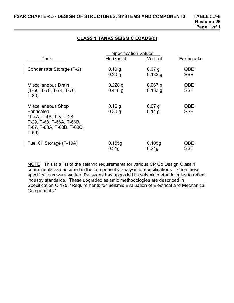
FSAR CHAPTER 5 - DESIGN OF STRUCTURES, SYSTEMS AND COMPONENTS TABLE 5.7-8 Revision 25 Page 1 of 1 CLASS 1 TANKS SEISMIC LOADS(g)
Specification Values
Tank Horizontal Vertical Earthquake Condensate Storage (T-2) 0.10 g 0.07 g OBE
0.20 g 0.133 g SSE Miscellaneous Drain 0.228 g 0.067 g OBE (T-60, T-70, T-74, T-76, 0.418 g 0.133 g SSE T-80) Miscellaneous Shop 0.16 g 0.07 g OBE Fabricated 0.30 g 0.14 g SSE (T-4A, T-4B, T-5, T-28 T-29, T-63, T-66A, T-66B, T-67, T-68A, T-68B, T-68C, T-69) Fuel Oil Storage (T-10A) 0.155g 0.105g OBE 0.31g 0.21g SSE NOTE: This is a list of the seismic requirements for various CP Co Design Class 1 components as described in the components' analysis or specifications. Since these specifications were written, Palisades has upgraded its seismic methodologies to reflect industry standards. These upgraded seismic methodologies are described in Specification C-175, "Requirements for Seismic Evaluation of Electrical and Mechanical Components."

FSAR CHAPTER 5 - DESIGN OF STRUCTURES, SYSTEMS AND COMPONENTS TABL E 5.7-9 Revision 27 Page 1 of 2 SAFE TY-RELATED HYDRAULIC SHOCK SUPPRESSORS (SNUBBERS)
Snubber in Snubbers Snubbers Snubbers Palisades High Radiation Especially Inaccessi ble Accessible ID Area During Difficult During Normal During Normal Number Sy stem Location Shutdown To Remove Operation Operation
37 ESS GC-1 LPSI Pump Discharge X
38 ESS GC-1 LPSI Pump Discharge X
42 ESS GC-1 LPSI Pump Discharge X
44 ESS GC-1 LPSI Pump Discharge (After CV-3025 SDHX to LPSI Valves) X
46 MSS Steam Generator A, Restraint 1-SS-1 X X X
47 MSS Steam Generator A, Restraint 1-SS-2 X X X
48 MSS Steam Generator A, Restraint 1-SS-3 X X X
49 MSS Steam Generator A, Restraint 1-SS-4 X X X
50 MSS Steam Generator A, Restraint 1-SS-5 X X X
51 MSS Steam Generator A, Restraint 1-SS-6 X X X
52 MSS Steam Generator A, Restraint 1-SS-7 X X X
53 MSS Steam Generator A, Restraint 1-SS-8 X X X
54 MSS Steam Generator B, Restraint 2-SS-1 X X X
55 MSS Steam Generator B, Restraint 2-SS-2 X X X

FSAR CHAPTER 5 - DESIGN OF STRUCTURES, SYSTEMS AND COMPONENTS TABL E 5.7-9 Revision 27 Page 2 of 2 SAFE TY-RELATED HYDRAULIC SHOCK SUPPRESSORS (SNUBBERS)
Snubber in Snubbers Snubbers Snubbers Palisades High Radiation Especially Inaccessi ble Accessible ID Area During Difficult During Normal During Normal Number Sy stem Location Shutdown To Remove Operation Operation
56 MSS Steam Generator B, Restraint 2-SS-3 X X X
57 MSS Steam Generator B, Restraint 2-SS-4 X X X
58 MSS Steam Generator B, Restraint 2-SS-5 X X X
59 MSS Steam Generator B, Restraint 2-SS-6 X X X
60 MSS Steam Generator B, Restraint 2-SS-7 X X X
61 MSS Steam Generator B, Restraint 2-SS-8 X X X
62 SIS On Low-Pressure Safety Injection Line Inside Containment Before MOVs X
63 SIS Low-Pressure Safety Injection to T-82C X
64 SIS Low-Pressure Safety Injection to T-82C X

FSAR CHAPTER 5 - DESIGN OF STRUCTURES, SYSTEMS AND COMPONENTS TABLE 5.7-10 Revision 21 Page 1 of 1
SAFETY-RELATED MECHANICAL SHOCK SUPPRESSORS (SNUBBERS)
Snubber in Snubbers Snubbers Snubbers Palisades High Radiation Especially Inaccessible Accessible ID Area During Difficult During Normal During Normal Number System Location Shutdown To Remove Operation Operation 68 SIS CC-4 From Safety Injection Tank T-82B X X X 70 SIS CC-4 From Safety Injection Tank T-82D X X 71 SIS CC-4 From Safety Injection Tank T-82D X X 79 ESS CV-3084 actuator support X X 80 ESS CV-3085 actuator support X X
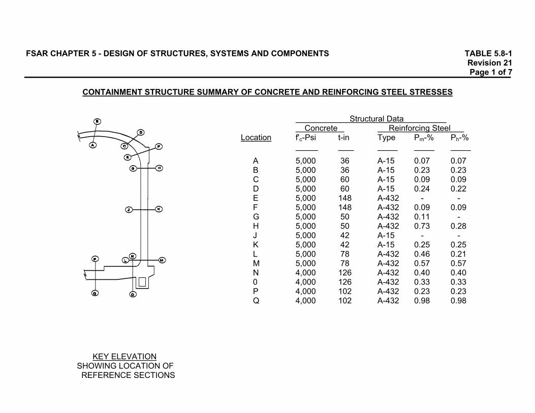
FSAR CHAPTER 5 - DESIGN OF STRUCTURES, SYSTEMS AND COMPONENTS TABLE 5.8-1 Revision 21 Page 1 of 7
CONTAINMENT STRUCTURE SUMMARY OF CONCRETE AND REINFORCING STEEL STRESSES
Structural Data Concrete Reinforcing Steel
Location f'c-Psi t-in Type Pm-% Ph-%
A 5,000 36 A-15 0.07 0.07 B 5,000 36 A-15 0.23 0.23 C 5,000 60 A-15 0.09 0.09 D 5,000 60 A-15 0.24 0.22 E 5,000 148 A-432 - - F 5,000 148 A-432 0.09 0.09 G 5,000 50 A-432 0.11 - H 5,000 50 A-432 0.73 0.28 J 5,000 42 A-15 - - K 5,000 42 A-15 0.25 0.25 L 5,000 78 A-432 0.46 0.21 M 5,000 78 A-432 0.57 0.57 N 4,000 126 A-432 0.40 0.40 0 4,000 126 A-432 0.33 0.33 P 4,000 102 A-432 0.23 0.23 Q 4,000 102 A-432 0.98 0.98
KEY ELEVATION SHOWING LOCATION OF REFERENCE SECTIONS

FSAR CHAPTER 5 - DESIGN OF STRUCTURES, SYSTEMS AND COMPONENTS TABLE 5.8-1 Revision 21 Page 2 of 7
CONTAINMENT STRUCTURE SUMMARY OF CONCRETE AND REINFORCING STEEL STRESSES
NOTES: 1. This table presents the results of the design effort for several load combinations of Subsections 5.8.3 which were
considered to be significant in the design of the containment structure. 2. Loading Cases I, II and III are working stress analyses whereas Loading Cases IV, V and VI are yield strength analyses. 3. Because the live load (see Subsection 5.3.1.2) on the containment structure is insignificant, it was arbitrarily not included in
the tabulation of Load Cases II and III.
4. The load combinations in this table are meant to illustrate gross structural behavior. Therefore, the effects of "H" (see Subsection 5.8.3.1.3), which are local, have not been included in Load Cases V and VI.
5. For notation and allowable stresses, see Sheet 2. 6. The stresses shown for the load cases including Ta are based on cracked section analysis unless noted by*. 7. Stresses computed for the working stress loading cases may exceed their associated allowables provided that the yield
strength criteria of Subsection 5.8.5.2.4 are satisfied. 8. All concrete extreme fiber stresses are shown for the inside surface. Outside surface stresses are indicated by ( ). The
stresses listed are the controlling stresses for that section. 9. Computed v allowable ratios for Cases IV, V and VI include appropriate Ø factors; eg, σa = σa .
fa Øa f'c 10. Allowable shear stresses include stirrups wherever applicable.

FSAR CHAPTER 5 - DESIGN OF STRUCTURES, SYSTEMS AND COMPONENTS TABLE 5.8-1 Revision 21 Page 3 of 7
CONTAINMENT STRUCTURE SUMMARY OF CONCRETE AND REINFORCING STEEL STRESSES
Allowable Stresses Notation Working Stress Design Yield Strength Design D Dead Load Shell Concrete fa = 1,500 psi fa = 0/a f'c = (0.85)(5,000) = 4,250 psi Fi Initial Prestress Ff Final Prestress P DBA Pressure fce = 3,000 psi fce = 0/ce f'c = (0.90)(5,000) = 4,500 psi E OBE E' SSE Base Concrete fa = 1,200 psi fa = 0/a f'c = (0.85)(4,000) = 3,400 psi Ta DBA Temperature f'c Ultimate Concrete Stress fce = 1,800 psi fce = 0/ce f'c = (0.90)(4,000) = 3,600 psi fy Reinforcing Steel Yield Stress fa Allowable Concrete Membrane Compressive Stress Steel - A-15 fs = 20,000 psi fs = 0/ fy = (0.90)(40,000) = 36,000 psi fce Allowable Concrete Combined Compressive Stress
(Membrane + Flexure) A-432 fs = 30,000 psi fs = 0/ fy = (0.90)(60,000) = 54,000 psi v Allowable Concrete Shear Stress Including Stirrups If Applicable NOTE: Allowable shear stresses are computed in accordance with the provi- fs Allowable Reinforcing Steel Stress sions of Subsections 5.8.5.2.3 and 5.8.5.2.4. 0/ Yield Capacity Reduction Factor σa Concrete Membrane Stress σe Concrete Combined Stress
(Membrane + Flexure) τ Concrete Shear Stress σ Reinforcing Steel Stress h Subscript Indicating Hoop Direction m Subscript Indicating Meridional Direction a Subscript Indicating Association With fa ce Subscript Indicating Association With fce t Thickness of Concrete Section Ph Hoop Steel Percentage Pm Meridional Steel Percentage + Tensile Stresses - Compressive Stresses
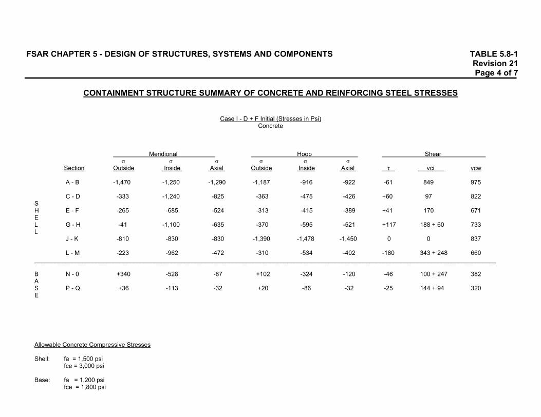
FSAR CHAPTER 5 - DESIGN OF STRUCTURES, SYSTEMS AND COMPONENTS TABLE 5.8-1 Revision 21 Page 4 of 7
CONTAINMENT STRUCTURE SUMMARY OF CONCRETE AND REINFORCING STEEL STRESSES
Case I - D + F Initial (Stresses in Psi) Concrete
Meridional Hoop Shear σ σ σ σ σ σ
Section Outside Inside Axial Outside Inside Axial τ vci vcw
A - B -1,470 -1,250 -1,290 -1,187 -916 -922 -61 849 975
C - D -333 -1,240 -825 -363 -475 -426 +60 97 822 S H E - F -265 -685 -524 -313 -415 -389 +41 170 671 E L G - H -41 -1,100 -635 -370 -595 -521 +117 188 + 60 733 L
J - K -810 -830 -830 -1,390 -1,478 -1,450 0 0 837
L - M -223 -962 -472 -310 -534 -402 -180 343 + 248 660 _______________________________________________________________________________________________________________________________________ B N - 0 +340 -528 -87 +102 -324 -120 -46 100 + 247 382 A S P - Q +36 -113 -32 +20 -86 -32 -25 144 + 94 320 E Allowable Concrete Compressive Stresses Shell: fa = 1,500 psi
fce = 3,000 psi Base: fa = 1,200 psi
fce = 1,800 psi
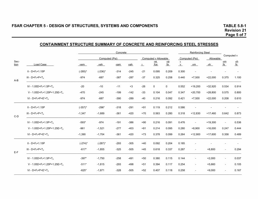
FSAR CHAPTER 5 - DESIGN OF STRUCTURES, SYSTEMS AND COMPONENTS TABLE 5.8-1 Revision 21 Page 5 of 7 CONTAINMENT STRUCTURE SUMMARY OF CONCRETE AND REINFORCING STEEL STRESSES
Concrete Reinforcing Steel Computed v
Computed (Psi) Computed v Allowable Computed (Psi) Allowable Sec- σe σa τ σm σh tion Load Case σem σeh σam σah τ fce fa v σm σh fs fs
II - D+Ff+1.15P (-285)* (-236)* -314 -245 -21 0.095 0.209 0.300 - - - -
III - D+Ff+P+Ta -974 -687 -387 -287 -37 0.325 0.258 0.440 +7,500 +22,000 0.375 1.100 A-B ____________________________________________________________________________________________________________________________________________________
IV - 1.05D+Ff+1.5P+Ta -20 -10 -11 +3 -26 0 0 0.552 +19,200 +32,920 0.534 0.914
V - 1.05D+Ff+1.25P+1.25E+Ta -470 -245 -199 -142 -33 0.104 0.047 0.347 +20,700 +28,800 0.575 0.800
VI - D+Ff+P+E'+Ta -974 -687 -390 -289 -40 0.216 0.092 0.421 +7,500 +22,000 0.208 0.610 _____________________________________________________________________________________________________________________________________________________________
II - D+Ff+1.15P (-357)* -296* -318 -291 +91 0.119 0.212 0.586 - - - -
III - D+Ff+P+Ta -1,347 -1,689 -361 -420 +70 0.563 0.280 0.318 +12,830 +17,460 0.642 0.873 C-D ____________________________________________________________________________________________________________________________________________________
IV - 1.05D+Ff+1.5P+Ta -593* -974 -191 -386 +90 0.216 0.091 0.476 - +19,300 - 0.536
V - 1.05D+Ff+1.25P+1.25E+Ta -961 -1,521 -277 -403 +81 0.214 0.095 0.280 +8,900 +16,000 0.247 0.444
VI - D+Ff+P+E'+Ta -1,390 -1,704 -361 -420 +73 0.378 0.099 0.264 +12,900 +17,600 0.358 0.489 _____________________________________________________________________________________________________________________________________________________________
II - D+Ff+1.15P (-274)* (-287)* -293 -305 +40 0.092 0.204 0.185 - - - -
III - D+Ff+P+Ta -617* -1,855 -325 -505 +45 0.618 0.337 0.287 - +8,800 - 0.294 E-F ____________________________________________________________________________________________________________________________________________________
IV - 1.05D+Ff+1.5P+Ta -397* -1,750 -258 -491 +50 0.380 0.115 0.144 - +2,000 - 0.037
V - 1.05D+Ff+1.25P+1.25E+Ta -511* -1,815 -293 -498 +51 0.394 0.117 0.254 - +5,660 - 0.105
VI - D+Ff+P+E'+Ta -625* -1,871 -328 -505 +52 0.407 0.118 0.258 - +9,000 - 0.167 _____________________________________________________________________________________________________________________________________________________________

FSAR CHAPTER 5 - DESIGN OF STRUCTURES, SYSTEMS AND COMPONENTS TABLE 5.8-1 Revision 21 Page 6 of 7 CONTAINMENT STRUCTURE SUMMARY OF CONCRETE AND REINFORCING STEEL STRESSES
Concrete Reinforcing Steel Computed v
Computed (Psi) Computed v Allowable Computed (Psi) Allowable Sec- σe σa τ σm σh tion Load Case σem σeh σam σah τ fce fa v σm σh fs fs
II - D+Ff+1.15P -197 -187 -136 -185 +8 0.066 0.123 0.056 - - - -
III - D+Ff+P+Ta -1,511 -1,384 -215 -253 +15 0.503 0.169 0.137 +26,220 +25,540 0.875 0.850 G-H ____________________________________________________________________________________________________________________________________________________
IV - 1.05D+Ff+1.5P+Ta -530 -777 -36 -151 -20 0.173 0.035 0.179 +26,340 +27,500 0.488 0.510
V - 1.05D+Ff+1.25P+1.25E+Ta -997 -1,079 -126 -202 -5 0.240 0.048 0.047 +25,350 +27,450 0.470 0.509
VI - D+Ff+P+E'+ta -1,550 -1,400 -216 -253 +15 0.345 0.060 0.141 +26,400 +26,000 0.489 0.481 _____________________________________________________________________________________________________________________________________________________________
II - D+Ff+1.15P -212 -337 -217 -348 +13 0.112 0.232 0.260 - - - -
III - D+Ff+P+Ta -1,411 -1,705 -297 -461 +11 0.570 0.308 0.156 +15,300 +10,800 0.765 0.540 J-K ____________________________________________________________________________________________________________________________________________________
IV - 1.05D+Ff+1.5P+Ta -241 -312 -80 -69 +17 0.069 0.019 0.120 +25,600 +25,250 0.711 0.702
V - 1.05D+Ff+1.25P+1.25E+Ta -741 -1,667 -189 -265 +14 0.370 0.062 0.100 +20,300 +10,730 0.564 0.298
VI - D+Ff+P+E'+Ta -1,450 -1,800 -300 -463 +11 0.400 0.109 0.080 +18,000 +13,000 0.500 0.361 _____________________________________________________________________________________________________________________________________________________________
II - D+Ff+1.15P (-308) -237 -188 -250 -47 0.102 0.167 0.147 - - - -
III - D+Ff+P+Ta -807 -976 -215 -183 -199 0.325 0.143 0.307 +6,040 +14,550 0.201 0.485 L-M ____________________________________________________________________________________________________________________________________________________ IV - 1.05D+Ff+1.5P+Ta -120 -654 -108 -174 -65 0.142 0.041 0.203 0 +15,250 0 0.282
V - 1.05D+Ff+1.25P+1.25E+Ta -1,464 -300 -38 +165 -157 0.318 Net 0.620 +12,940 +34,200 0.240 0.634 Ten- sion
VI - D+Ff+P+E'+Ta -1,340 0 -76 +306 -213 0.292 Net 0.677 +23,240 +47,600 0.431 0.882
Ten- sion
______________________________________________________________________________________________________________________________________________________________
II - D+Ff+1.15P (+124)* -285* 0 -72 -88 0.158 fa = 0.209 - - - -

FSAR CHAPTER 5 - DESIGN OF STRUCTURES, SYSTEMS AND COMPONENTS TABLE 5.8-1 Revision 21 Page 7 of 7 CONTAINMENT STRUCTURE SUMMARY OF CONCRETE AND REINFORCING STEEL STRESSES
Concrete Reinforcing Steel Computed v
Computed (Psi) Computed v Allowable Computed (Psi) Allowable Sec- σe σa τ σm σh tion Load Case σem σeh σam σah τ fce fa v σm σh fs fs
0.3 III - D+Ff+P+Ta -583 -1,114 -76 -113 -91 0.620 f'c 0.255 +14,780 +20,060 0.492 0.670
N-O ___________________________________________________________________________________________________ not ____________________________________ ap-
IV - 1.05D+Ff+1.5P+Ta -30 -798 -33 -85 -149 0.222 pli- 0.394 +9,300 +21,460 0.172 0.398 ca-
V - 1.05D+Ff+1.25P+1.25E+Ta 0 -735 +2 -266 -243 0.204 ble 0.630 +10,140 +35,130 0.188 0.650 to
VI - D+Ff+P+E'+Ta -38 -686 +4 -351 -266 0.191 slab. 0.820 +12,800 +38,100 0.237 0.705 _____________________________________________________________________________________________________________________________________________________________
II - D+Ff+1.15P -81* -70* +149 +152 -1 0.045 0.008 - - - - M T
III - D+Ff+P+Ta -338 0 +139 +166 -5 0.188 E E 0.035 +17,540 +21,050 0.585 0.702 P-Q __________________________________________________________________________________________________ M N ____________________________________
B S IV - 1.05D+Ff+1.5P+Ta -459 0 +225 +253 -15 0.128 R I 0.112 +19,300 +29,900 0.358 0.554
A O V - 1.05D+Ff+1.25P+1.25E+Ta -845 0 +198 +281 -90 0.234 N N 0.660 +31,000 +37,400 0.575 0.693
E VI - D+Ff+P+E'+Ta -1,538 -381 +163 +296 -133 0.424 0.842 +29,250 +44,000 0.542 0.815
______________________________________________________________________________________________________________________________________________________________

FSAR CHAPTER 5 - DESIGN OF STRUCTURES, SYSTEMS AND COMPONENTS TABLE 5.8-2 Revision 21 Page 1 of 2 CONTAINMENT STRUCTURE TENDON ANCHORAGE ZONE REINFORCEMENT STRESSES
Computed Allowable Stress Stress 0.9 fy Psi Psi
Buttress Vertical Reinforcement Bursting 8,000 D+Ff+1.5P+Ta 14,000 22,000 36,000 Hoop Reinforcement D+Ff+1.5P+Ta 16,000 36,000 Radial Reinforcement Bursting 19,000 36,000 Ring Girder - Dome Tendons Spiral Reinforcement 7,000 36,000 Vertical Reinforcement Bursting 11,900 D+Ff+1.5P+Ta 16,600 28,500 54,000 Hoop Reinforcement Bursting 23,700 D+Ff+1.5P+Ta 11,300 35,000 54,000 Ring Girder - Vertical Tendons Radial Reinforcement Bursting 39,000 D+Ff+1.5P+Ta 11,000 50,000 54,000 Hoop Reinforcement Bursting 16,000 D+Ff+1.5P+Ta 11,000 27,000 54,000

FSAR CHAPTER 5 - DESIGN OF STRUCTURES, SYSTEMS AND COMPONENTS TABLE 5.8-2 Revision 21 Page 2 of 2 CONTAINMENT STRUCTURE TENDON ANCHORAGE ZONE REINFORCEMENT STRESSES
Computed Allowable Stress Stress 0.9 fy Psi Psi
Base Slab Radial Reinforcement Bursting 30,000 D+Ff+Ta+E' 23,000 53,000 54,000 Hoop Reinforcement Bursting Force 30,000 54,000

FSAR CHAPTER 5 - DESIGN OF STRUCTURES, SYSTEMS AND COMPONENTS TABLE 5.8-3 Revision 21 Page 1 of 1 CONTAINMENT STRUCTURE LINER PLATE ANCHOR ANALYSIS
Nominal Initial Factor of Plate Inward Anchor Anchor Safety Thickness Displacement Spacing L1 Spacing L2 Against
Case (in) (in) (in) (in) Failure I 0.25 0.125 15 15 37.0 II 0.25 0.125 15 15 19.4 III 0.25 0.125 15 15 9.9 IV 0.25 0.125 15 15 6.28 V 0.25 0.25 30 15 4.25

FSAR CHAPTER 5 - DESIGN OF STRUCTURES, SYSTEMS AND COMPONENTS TABLE 5.8-4 Revision 32 Page 1 of 11 CONTAINMENT PENETRATIONS AND APPENDIX J TEST REQUIREMENTS
POST PEN LOCA
SYSTEM NAME AND CLASS VALVE VALVE TYPE OR LOCATION NOR (SIAS, PEN NO. SERVICE LINE SIZE NO. ID NO. DESCRIPTION OC IC MAL CHR,CHP) TEST REQUIREMENTS 1A PURGE AIR EXHAUST A1 CV-1805 AO BUTF VLV X ELC C TYPE C TEST
(8" Ø) CV-1806 AO BUTF VLV X ELC C MV-VA506 MAN GA TEST VLV X LC C
1B PURGE AIR EXHAUST A2 MV-VA100 MAN GATE VLV X LC C TYPE C TEST
BYPASS (4" Ø) MV-VA101 MAN GATE VLV X LC C MV-VA507 MAN GL TEST VLV X LC C
1C PURGE AIR EXHAUST A1 CV-1807 AO BUTF VLV X ELC C TYPE C TEST
(8" Ø) CV-1808 AO BUTF VLV X ELC C MV-VA508 MAN GA TEST VLV X LC C
2 MAIN STEAM LINE C1 CV-0510 POS CK VLV X O C NOT REQUIRED TO BE TESTED; S/G SHELL IS
(S/G E-50A) MO-0510 MSIV BYPASS VLV X NC C CONSIDERED AN EXTENSION OF THE CONTAINMENT (36" Ø) CV-0781 AO GL VLV X NC C BOUNDARY.
CV-0782 AO GL VLV X NC C CV-0522B AO GL VLV X NC C MV-MS500 MAN GL VLV X LC C MV-MS515 MAN GA VLV X O O MV-MS521 MAN GL VLV X LC C MV-MS522 MAN GA VLV X LC C MV-MS519 MAN GA VLV X O O MV-MS517 MAN GL VLV X LC C MV-MS518 MAN GA VLV X LC C MV-FW506A MAN GA VLV X O O MV-FW508A MAN GA VLV X LC C MV-FW711 MAN GA VLV X LC C MV-FW712 MAN GA VLV X LC C
3 MAIN STEAM LINE C1 CV-0501 POS CK VLV X O C NOT REQUIRED TO BE TESTED; S/G SHELL IS CONSIDERED
(S/G E-50B) MO-0501 MSIV BYPASS VLV X NC C AN EXTENSION OF THE CONTAINMENT BOUNDARY. (36" Ø) CV-0779 AO GL VLV X NC C
CV-0780 AO GL VLV X NC C MV-MS152 MAN GA VLV X LC C MV-MS523 MAN GA VLV X O O MV-MS525 MAN GL VLV X LC C MV-MS526 MAN GA VLV X LC C MV-MS527 MAN GA VLV X O O MV-MS529 MAN GL VLV X LC C MV-MS530 MAN GA VLV X LC C
4 SEALED N/A PENETRATION TESTED DURING TYPE A TEST.

FSAR CHAPTER 5 - DESIGN OF STRUCTURES, SYSTEMS AND COMPONENTS TABLE 5.8-4 Revision 32 Page 2 of 11 CONTAINMENT PENETRATIONS AND APPENDIX J TEST REQUIREMENTS
POST PEN LOCA
SYSTEM NAME AND CLASS VALVE VALVE TYPE OR LOCATION NOR (SIAS, PEN NO. SERVICE LINE SIZE NO. ID NO. DESCRIPTION OC IC MAL CHR,CHP) TEST REQUIREMENTS 5 S/G (E-50A) C1 CV-0767 AO ANGLE VLV X NO C NOT REQUIRED TO BE TESTED; S/G SHELL IS CONSIDERED
BLOWDOWN AN EXTENSION OF THE CONTAINMENT BOUNDARY. (4" Ø)
6 S/G (E-50B) C1 CV-0768 AO ANGLE VLV X NO C NOT REQUIRED TO BE TESTED; S/G SHELL IS CONSIDERED
BLOWDOWN AN EXTENSION OF THE CONTAINMENT BOUNDARY. (4" Ø)
7 FEEDWATER TO S/G C1 CK-FW702 CHECK VLV X O C NOT REQUIRED TO BE TESTED; S/G SHELL IS CONSIDERED
(E-50A) (18" Ø) MV-FW746 MAN GA VLV X LC C AN EXTENSION OF THE CONTAINMENT BOUNDARY. 8 FEEDWATER TO S/G C1 MV-FW747 MAN GA VLV X LC C NOT REQUIRED TO BE TESTED; S/G SHELL IS CONSIDERED
(E-50B) (18" Ø) CK-FW701 CHECK VLV X O C AN EXTENSION OF THE CONTAINMENT BOUNDARY. 9 AUX FEED TO S/G C1 CK-FW704 CHECK VLV X NC O NOT REQUIRED TO BE TESTED; S/G SHELL IS CONSIDERED
(E-50A) (4" Ø) CK-FW729 CHECK VLV X NC O AN EXTENSION OF THE CONTAINMENT BOUNDARY. MV-FW720 MAN GL VLV X LC C
10 SERVICE AIR A2 MV-CA122 MAN GA VLV X LC C TYPE C TEST
(2" Ø) MV-CA728 MAN GA VLV X LC C MV-CA142 MAN GA TEST VLV X LC C
11 CONDENSATE TO A1 CV-0939 AO GL VLV X NO C TYPE C TEST
SHIELD COOLING CK-CD401 CHECK VLV X O C SURGE TANK (1 1/2" Ø) MV-CD536 MAN GL TEST VLV X LC C
12 SERVICE WATER C1 CV-0847 AC BUTF VLV X ELO O NOT REQUIRED TO BE TESTED. SYSTEM WILL BE IN OPERATION SUPPLY (16" Ø) MV-SW571 MAN GA VLV X LC C FOLLOWING ACCIDENT. 13 SERVICE WATER C1 CV-0824 AC BUTF VLV X ELO O NOT REQUIRED TO BE TESTED. SYSTEM WILL BE IN OPERATION
RETURN (16" Ø) MV-SW572 MAN GA VLV X LC C FOLLOWING ACCIDENT. MV-SW385 MAN GA VLV X LC C

FSAR CHAPTER 5 - DESIGN OF STRUCTURES, SYSTEMS AND COMPONENTS TABLE 5.8-4 Revision 32 Page 3 of 11 CONTAINMENT PENETRATIONS AND APPENDIX J TEST REQUIREMENTS
POST PEN LOCA
SYSTEM NAME AND CLASS VALVE VALVE TYPE OR LOCATION NOR (SIAS, PEN NO. SERVICE LINE SIZE NO. ID NO. DESCRIPTION OC IC MAL CHR,CHP) TEST REQUIREMENTS 14 COMPONENT COOLING C1 CK-CC910 CHECK VLV X O O/C NOT REQUIRED TO BE TESTED.
WATER IN (10" Ø) MV-CC507 MAN GL TEST VLV X LC C 15 COMPONENT COOLING C1 CV-0911 AC BUTF X NO O/C NOT REQUIRED TO BE TESTED.
WATER OUT (10" Ø) 16 S/G (E-50A) C1 CV-0739 AO ANGLE VLV X C C NOT REQUIRED TO BE TESTED; S/G SHELL IS CONSIDERED
RECIRCULATION (4" Ø) AN EXTENSION OF THE CONTAINMENT BOUNDARY. 17 CONTAINMENT PRESSURE A2 MV-VA1802B MAN NEEDLE VALVE X LC C TYPE C TEST
INSTRUMENTATION MV-VA1802C MAN NEEDLE VALVE X LC C (4 X 1/2" Ø) MV-VA1804B MAN NEEDLE VALVE X LC C
MV-VA1804C MAN NEEDLE VALVE X LC C MV-VA1812A MAN NEEDLE VALVE X LC C MV-VA1812C MAN GL VALVE X LC C MV-VA1814A MAN NEEDLE VALVE X LC C MV-VA1814B MAN NEEDLE VALVE X LC C
17A CONTAINMENT SUMP LEVEL MV-VA1814F MAN GL VALVE X LC C INSTRUMENTATION (1/2" Ø) MV-VA1814G MAN GL VALVE X LC C
18 FUEL TRANSFER X MZ-18 36" FLANGE X C C TYPE B TEST OF FLANGES TUBE (36" Ø) MZ-18-1 TEST CONN W/CAP X C C 18A (WINCH CABLE) MZ-18A 2" FLANGE X C C
MZ-18A-1 TEST CONN W/CAP X C C

FSAR CHAPTER 5 - DESIGN OF STRUCTURES, SYSTEMS AND COMPONENTS TABLE 5.8-4 Revision 32 Page 4 of 11 CONTAINMENT PENETRATIONS AND APPENDIX J TEST REQUIREMENTS
POST PEN LOCA
SYSTEM NAME AND CLASS VALVE VALVE TYPE OR LOCATION NOR (SIAS, PEN NO. SERVICE LINE SIZE NO. ID NO. DESCRIPTION OC IC MAL CHR,CHP) TEST REQUIREMENTS 19 PERSONNEL LOCK X OUTER DOOR - X C C TYPE B TEST
- PRESS EQUAL VLV X C C 19-3 - TEST CONN X C C 19-4 CAP INST TUBE W/CAP X C C 19-5 MV-VA532 MAN BALL TEST VLV X LC C 19-6 MV-VA533 MAN GA TEST VLV X LC C
INNER DOOR - X C C - PRESS EQUAL VLV X C C
19-1 CAP INST TUBE W/CAP X C C 19-2 CAP INST TUBE W/CAP X C C 20 SPARE N/A PENETRATION TESTED DURING TYPE A TEST. 21 HYDROGEN MONITORING A1 SV-2415A SOLENOID VLV X C C/O TYPE C TEST
RETURN LINE LEFT SV-2415B SOLENOID VLV X C C/O CHANNEL (1/2" Ø) MV-WG531B MAN TEST VLV X LC C
21A HYDROGEN MONITORING A1 SV-2413A SOLENOID VLV X C C/O TYPE C TEST
SUPPLY LINE LEFT SV-2413B SOLENOID VLV X C C/O CHANNEL (1/2" Ø) MV-WG531A MAN TEST VLV X LC C
22 HIGH PRESSURE SAFETY X CK-ES3250 CHECK VLV X C O NOT REQUIRED TO BE TESTED. SYSTEM WILL BE IN OPERATION
INJECTION TRAIN 2 (6" Ø) CK-ES3251 CHECK VLV X C O FOLLOWING ACCIDENT. CK-ES3252 CHECK VLV X C O CK-ES3253 CHECK VLV X C O CK-ES3409 CHECK VLV X C C/O CV-3018 AO GA VLV X ELC C/O CV-3036 AC GA VLV X ELO O MO-3072 MO GL VLV X ELC C/O MV-ES561 MAN GL VLV X LC LC

FSAR CHAPTER 5 - DESIGN OF STRUCTURES, SYSTEMS AND COMPONENTS TABLE 5.8-4 Revision 32 Page 5 of 11 CONTAINMENT PENETRATIONS AND APPENDIX J TEST REQUIREMENTS
POST PEN LOCA
SYSTEM NAME AND CLASS VALVE VALVE TYPE OR LOCATION NOR (SIAS, PEN NO. SERVICE LINE SIZE NO. ID NO. DESCRIPTION OC IC MAL CHR,CHP) TEST REQUIREMENTS 23 HIGH PRESSURE SAFETY X CK-ES3104 CHECK VLV X C O NOT REQUIRED TO BE TESTED. SYSTEM WILL BE IN OPERATION
INJECTION TRAIN 1 (6" Ø) CK-ES3119 CHECK VLV X C O FOLLOWING ACCIDENT. CK-ES3134 CHECK VLV X C O CK-ES3149 CHECK VLV X C O CK-ES3408 CHECK VLV X C C/O MV-ES3007A MAN GL TEST VLV X LC LC MV-ES3009A MAN GL TEST VLV X LC LC MV-ES3011A MAN GL TEST VLV X LC LC MV-ES3013A MAN GL TEST VLV X LC LC CV-3059 AC GA VLV X ELO O CV-3037 AO GA VLV X ELC C/O
24 SPARE N/A PENETRATION TESTED DURING TYPE A TEST. 25 CLEAN WASTE A1 CV-1064 AO GL VLV X NO C TYPE C TEST
RECEIVER TANK CV-1065 AO GL VLV X NO C VENT TO STACK (2" Ø) MV-CRW512 MAN GL TEST VLV X LC C
26 NITROGEN TO C2 CV-1358 AO GL VLV X NC C TYPE C TEST
CONTAINMENT CK-N2/400 CHECK VLV X C C (1" Ø) MV-N2/581 MAN GL TEST VLV X LC C
27 INTEGRATED LEAK RATE A2 MO-P1 MO BUTF VLV X ELC C TYPE C TEST OF VALVES
TEST LINE (6" Ø) MV-VA604 MAN GA TEST VLV X LC C MZ-27-1 FLANGE X C C TYPE B TEST OF FLANGE
28 CONTAINMENT AIR N/A CAPPED X C C PENETRATION TESTED DURING TYPE A TEST.
SAMPLE LINE (1/2" Ø) 29 CAPPED SPARE N/A CAP PIPE END W/ CAP X C C PENETRATION TESTED DURING TYPE A TEST.

FSAR CHAPTER 5 - DESIGN OF STRUCTURES, SYSTEMS AND COMPONENTS TABLE 5.8-4 Revision 32 Page 6 of 11 CONTAINMENT PENETRATIONS AND APPENDIX J TEST REQUIREMENTS
POST PEN LOCA
SYSTEM NAME AND CLASS VALVE VALVE TYPE OR LOCATION NOR (SIAS, PEN NO. SERVICE LINE SIZE NO. ID NO. DESCRIPTION OC IC MAL CHR,CHP) TEST REQUIREMENTS 30 CONTAINMENT SPRAY X CV-3001 AC DRAG GL VLV X NC O/T NOT REQUIRED TO BE TESTED. SYSTEM WILL BE IN OPERATION
PUMP DISCHARGE CK-ES3226 CHECK VLV X C O FOLLOWING ACCIDENT. (8" Ø) MV-ES3344 MAN GL TEST VLV X LC C
MV-ES3227 MAN GL VLV X LC C 31 CONTAINMENT SPRAY X CV-3002 AC DRAG GL VLV X NC O/T NOT REQUIRED TO BE TESTED. SYSTEM WILL BE IN OPERATION
PUMP DISCHARGE CK-ES3216 CHECK VLV X C O FOLLOWING ACCIDENT. (8" Ø) MV-ES3346 MAN GL TEST VLV X LC C
MV-ES3217 MAN GL VLV X LC C 32 LOW PRESSURE X CK-ES3103 CHECK VLV X C O NOT REQUIRED TO BE TESTED. SYSTEM WILL BE IN OPERATION
SAFETY INJECTION CK-ES3118 CHECK VLV X C O FOLLOWING ACCIDENT. (12" Ø) CK-ES3133 CHECK VLV X C O
CK-ES3148 CHECK VLV X C O MV-ES3008 MAN GL TEST VLV X LC LC MV-ES3010 MAN GL TEST VLV X LC LC MV-ES3012 MAN GL TEST VLV X LC LC MV-ES3014 MAN GL TEST VLV X LC LC CV-3006 AC GL VLV X ELO O CV-3025 AO GL VLV X ELC C/O MV-ES3163 MAN GL VLV X LC C
33 SAFETY INJECTION C3 MV-ES3234 MAN BALL VLV X LC C TYPE C TEST
TANK DRAIN (2" Ø) MV-ES3234A MAN BALL VLV X LC C MV-ES3348A MAN BALL TEST VLV X LC C
34 SPARE N/A PENETRATION TESTED DURING TYPE A TEST.

FSAR CHAPTER 5 - DESIGN OF STRUCTURES, SYSTEMS AND COMPONENTS TABLE 5.8-4 Revision 27 Page 7 of 11 CONTAINMENT PENETRATIONS AND APPENDIX J TEST REQUIREMENTS
POST PEN LOCA
SYSTEM NAME AND CLASS VALVE VALVE TYPE OR LOCATION NOR (SIAS, PEN NO. SERVICE LINE SIZE NO. ID NO. DESCRIPTION OC IC MAL CHR,CHP) TEST REQUIREMENTS 35 SHUTDOWN COOLING B2 MO-3016 MO GA VLV X ELC C/O NOT REQUIRED TO BE TESTED. SYSTEM WILL BE IN OPERATION
RETURN (14" Ø) MO-3015 MO GA VLV X ELC C/O FOLLOWING ACCIDENT. 36 LETDOWN TO B1 CV-2009 AO GL VLV X NO C TYPE C TEST
PURIFICATION ION EXCHANGER (2" Ø)
37 PRIMARY SYSTEM C2 CV-1001 AO GL VLV X NC C TYPE C TEST
DRAIN TANK PUMP CK-CRW403 CHECK VLV X C C RECIRC (1 1/2" Ø) MV-CRW503 MAN GL TEST VLV X LC C
38 CONDENSATE RETURN N/A CAPPED X NC C PENETRATION TESTED DURING TYPE A TEST.
FROM STEAM HEATING UNITS (2" Ø)
39 CONTAINMENT HEATING N/A CAPPED X NC C PENETRATION TESTED DURING TYPE A TEST.
SYSTEM (4" Ø) 40 PRIMARY COOLANT SYSTEM B1 CV-1910 AO GL VLV X O/C C TYPE C TEST
SAMPLE LINE (1/2" Ø) CV-1911 AO GL VLV X O/C C MV-PC1170A MAN GL TEST VLV X LC C
40A HYDROGEN MONITOR A1 SV-2414A SOLENOID VLV X C C/O TYPE C TEST
RETURN LINE RIGHT SV-2414B SOLENOID VLV X C C/O CHANNEL (1/2" Ø) MV-WG530B MAN GL TEST VLV X LC C
40B HYDROGEN MONITOR A1 SV-2412A SOLENOID VLV X C C/O TYPE C TEST
SUPPLY LINE RIGHT SV-2412B SOLENOID VLV X C C/O CHANNEL (1/2" Ø) MV-WG530A MAN GL TEST VLV X LC C

FSAR CHAPTER 5 - DESIGN OF STRUCTURES, SYSTEMS AND COMPONENTS TABLE 5.8-4 Revision 27 Page 8 of 11 CONTAINMENT PENETRATIONS AND APPENDIX J TEST REQUIREMENTS
POST PEN LOCA
SYSTEM NAME AND CLASS VALVE VALVE TYPE OR LOCATION NOR (SIAS, PEN NO. SERVICE LINE SIZE NO. ID NO. DESCRIPTION OC IC MAL CHR,CHP) TEST REQUIREMENTS 41 DEGASIFIER PUMP A1 CV-1004 AO GL VLV X NO C TYPE C TEST
DISCHARGE (3" Ø) CK-CRW407 CHECK VLV X O C MV-CRW506 MAN GL TEST VLV X LC C
42 DEMINERALIZED C2 CV-0155 AO GL VLV X NC C TYPE C TEST
WATER TO QUENCH CK-PC155B CHECK VLV X C C TANK (2" Ø) MV-PC1126 MAN GL TEST VLV X LC C
43 SPARE N/A PENETRATION TESTED DURING TYPE A TEST. 44 CONTROLLED BLEEDOFF B1 CV-2083 AO GL VLV X NO C TYPE C TEST
FROM PCP'S (3/4" Ø) MV-CVC2083 MAN GL TEST VLV X LC C CV-2099 AO GL VLV X NO C
45 CHARGING PUMP B1 CK-CVC2110 CHECK VLV X O O NOT REQUIRED TO BE TESTED. SYSTEM WILL BE IN OPERATION
DISCHARGE (2" Ø) CV-2111 AC GL VLV X NO O FOLLOWING ACCIDENT. 46 CONTAINMENT VENT C2 CV-1101 AO GL VLV X NC C TYPE C TEST
HEADER (4" Ø) CV-1102 AO GL VLV X NC C MV-WG511 MAN GL TEST VLV X LC C
47 PRIMARY SYSTEM C2 CV-1002 AO GL VLV X NO C TYPE C TEST
DRAIN TANK PUMP CV-1007 AO GL VLV X NO C SUCTION (4" Ø) MV-CRW502 MAN GL TEST VLV X LC C
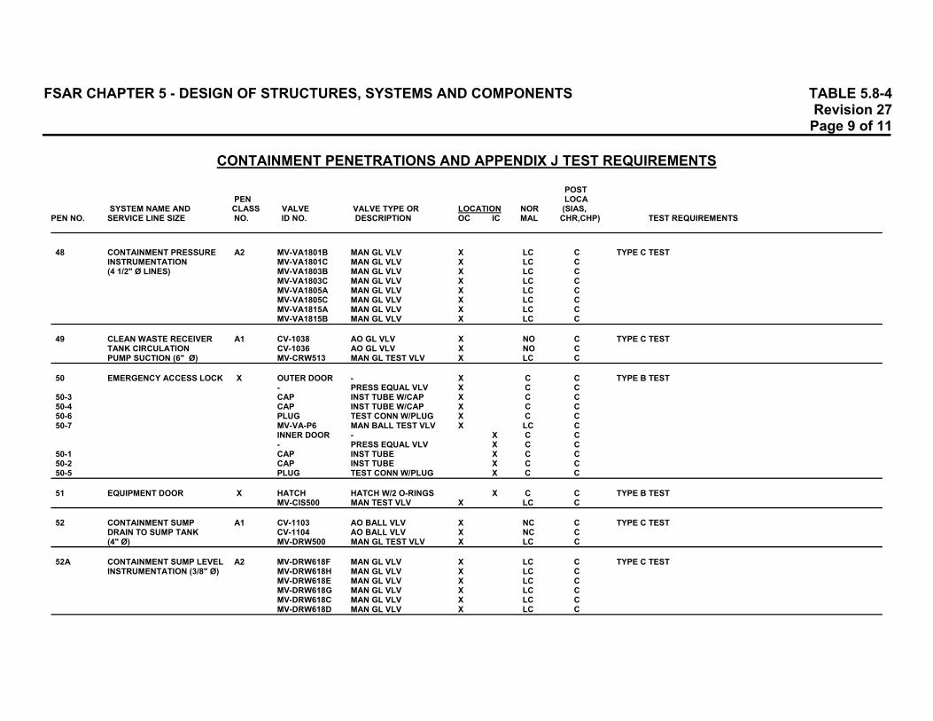
FSAR CHAPTER 5 - DESIGN OF STRUCTURES, SYSTEMS AND COMPONENTS TABLE 5.8-4 Revision 27 Page 9 of 11 CONTAINMENT PENETRATIONS AND APPENDIX J TEST REQUIREMENTS
POST PEN LOCA
SYSTEM NAME AND CLASS VALVE VALVE TYPE OR LOCATION NOR (SIAS, PEN NO. SERVICE LINE SIZE NO. ID NO. DESCRIPTION OC IC MAL CHR,CHP) TEST REQUIREMENTS 48 CONTAINMENT PRESSURE A2 MV-VA1801B MAN GL VLV X LC C TYPE C TEST
INSTRUMENTATION MV-VA1801C MAN GL VLV X LC C (4 1/2" Ø LINES) MV-VA1803B MAN GL VLV X LC C
MV-VA1803C MAN GL VLV X LC C MV-VA1805A MAN GL VLV X LC C MV-VA1805C MAN GL VLV X LC C MV-VA1815A MAN GL VLV X LC C MV-VA1815B MAN GL VLV X LC C
49 CLEAN WASTE RECEIVER A1 CV-1038 AO GL VLV X NO C TYPE C TEST
TANK CIRCULATION CV-1036 AO GL VLV X NO C PUMP SUCTION (6" Ø) MV-CRW513 MAN GL TEST VLV X LC C
50 EMERGENCY ACCESS LOCK X OUTER DOOR - X C C TYPE B TEST
- PRESS EQUAL VLV X C C 50-3 CAP INST TUBE W/CAP X C C 50-4 CAP INST TUBE W/CAP X C C 50-6 PLUG TEST CONN W/PLUG X C C 50-7 MV-VA-P6 MAN BALL TEST VLV X LC C
INNER DOOR - X C C - PRESS EQUAL VLV X C C
50-1 CAP INST TUBE X C C 50-2 CAP INST TUBE X C C 50-5 PLUG TEST CONN W/PLUG X C C 51 EQUIPMENT DOOR X HATCH HATCH W/2 O-RINGS X C C TYPE B TEST
MV-CIS500 MAN TEST VLV X LC C 52 CONTAINMENT SUMP A1 CV-1103 AO BALL VLV X NC C TYPE C TEST
DRAIN TO SUMP TANK CV-1104 AO BALL VLV X NC C (4" Ø) MV-DRW500 MAN GL TEST VLV X LC C
52A CONTAINMENT SUMP LEVEL A2 MV-DRW618F MAN GL VLV X LC C TYPE C TEST
INSTRUMENTATION (3/8" Ø) MV-DRW618H MAN GL VLV X LC C MV-DRW618E MAN GL VLV X LC C MV-DRW618G MAN GL VLV X LC C MV-DRW618C MAN GL VLV X LC C MV-DRW618D MAN GL VLV X LC C

FSAR CHAPTER 5 - DESIGN OF STRUCTURES, SYSTEMS AND COMPONENTS TABLE 5.8-4 Revision 27 Page 10 of 11 CONTAINMENT PENETRATIONS AND APPENDIX J TEST REQUIREMENTS
POST PEN LOCA
SYSTEM NAME AND CLASS VALVE VALVE TYPE OR LOCATION NOR (SIAS, PEN NO. SERVICE LINE SIZE NO. ID NO. DESCRIPTION OC IC MAL CHR,CHP) TEST REQUIREMENTS 52B CONTAINMENT SUMP LEVEL A2 MV-DRW619F MAN GL VLV X LC C TYPE C TEST
INSTRUMENTATION (3/8" Ø) MV-DRW619H MAN GL VLV X LC C MV-DRW619E MAN GL VLV X LC C MV-DRW619G MAN GL VLV X LC C MV-DRW619C MAN GL VLV X LC C MV-DRW619D MAN GL VLV X LC C
53 EAST SAFEGUARDS X CV-3029 AO GA VLV X ELC O NOT REQUIRED TO BE TESTED. SYSTEM WILL BE IN OPERATION
PUMPS SUCTION (24" Ø) FOLLOWING ACCIDENT. 54 WEST SAFEGUARDS X CV-3030 AO GA VLV X ELC O NOT REQUIRED TO BE TESTED. SYSTEM WILL BE IN OPERATION
PUMPS SUCTION (24" Ø) FOLLOWING ACCIDENT. 55 S/G (E-50B) C1 CV-0738 AO ANGLE VLV X C C NOT REQUIRED TO BE TESTED; S/G SHELL IS CONSIDERED
RECIRCULATION (4" Ø) AN EXTENSION OF THE CONTAINMENT BOUNDARY. 56 CONTAINMENT SUMP LEVEL A2 MV-VA606B MA GA VALVE X LC C TYPE C TEST
INSTRUMENTATION (1/2" Ø) MV-VA606C MA GA VALVE X LC C 57 SPARE N/A PENETRATION TESTED DURING TYPE A TEST. 58 SPARE N/A PENETRATION TESTED DURING TYPE A TEST. 59 SPARE N/A PENETRATION TESTED DURING TYPE A TEST. 60 SPARE N/A PENETRATION TESTED DURING TYPE A TEST. 61 SPARE N/A PENETRATION TESTED DURING TYPE A TEST. 62 SPARE N/A PENETRATION TESTED DURING TYPE A TEST. 63 SPARE N/A PENETRATION TESTED DURING TYPE A TEST. 64 REFUELING CAVITY FILL A2 MV-SFP121 MAN GA VLV X LC C TYPE C TEST
AND RECIRC (6" Ø) MV-SFP120 MAN GA VLV X LC C MV-SFP514 MAN GL TEST VLV X LC C
65 INSTRUMENT AIR C2 CV-1211 AC GL VLV X NO O TYPE C TEST OF CHECK VALVE
(1 1/2" Ø) CK-CA400 CHECK VLV X O O MV-CA612 MAN GL TEST VLV X LC C

FSAR CHAPTER 5 - DESIGN OF STRUCTURES, SYSTEMS AND COMPONENTS TABLE 5.8-4 Revision 27 Page 11 of 11 CONTAINMENT PENETRATIONS AND APPENDIX J TEST REQUIREMENTS
POST PEN LOCA
SYSTEM NAME AND CLASS VALVE VALVE TYPE OR LOCATION NOR (SIAS, PEN NO. SERVICE LINE SIZE NO. ID NO. DESCRIPTION OC IC MAL CHR,CHP) TEST REQUIREMENTS 66 ILRT A2 MV-VA601 MAN GA VLV X LC C TYPE C TEST
INSTRUMENT LINE MV-VA-L-6 MAN GA VLV X LC C (1 1/2" Ø) MV-VA603 MAN GA TEST VLV X LC C
MV-VA602 MAN GL TEST VLV X LC C 67 CLEAN WASTE A1 CV-1037 AO GL VLV X NO C TYPE C TEST
RECEIVER TANK PUMP CK-CRW408 CHECK VLV X O C RECIRC (3" Ø) MV-CRW515 MAN GL TEST VLV X LC C
68 AIR SUPPLY TO A1 CV-1813 AO BUTF VLV X ELC C TYPE C TEST
AIR ROOM (12" Ø) CV-1814 AO BUTF VLV X ELC C MV-VA505 MAN GL TEST VLV X LC C
69 CLEAN WASTE A1 CV-1045 AO GL VLV X NO C TYPE C TEST
RECEIVER TANK PUMP CV-1044 AO GL VLV X NO C SUCTION (4" Ø) MV-CRW518 MAN GL TEST VLV X LC C
70 SPARE N/A PENETRATION TESTED DURING TYPE A TEST. 71 SPARE N/A PENETRATION TESTED DURING TYPE A TEST. 72 REACTOR REFUELING A2 MV-SFP117 MAN GA VLV X LC C TYPE C TEST
CAVITY DRAIN (8" Ø) MV-SFP118 MAN GA VLV X LC C MV-SFP515 MAN GL TEST VLV X LC C
73 AUX FEED TO S/G C1 CK-FW703 CHECK VLV X NC O NOT REQUIRED TO BE TESTED; S/G SHELL IS CONSIDERED
(E-50B) (4" Ø) CK-FW728 CHECK VLV X NC O AN EXTENSION OF THE CONTAINMENT BOUNDARY. MV-FW718 MAN GL VLV X LC C
NORTH NORTH ELECTRICAL X CK-N2/462 CHECK VLV X NO C TYPE B TEST ELEC PENETRATION NITROGEN MV-N2/585 MAN GA TEST VLV X LC C TYPE C TEST OF CHECK VALVE PEN BLANKET SYSTEM SOUTH SOUTH ELECTRICAL X CK-N2/465 CHECK VLV X NO C TYPE B TEST ELEC PENETRATION NITROGEN MV-N2/588 MAN GA TEST VLV X LC C TYPE C TEST OF CHECK VALVE PEN BLANKET SYSTEM NOTE: TEST VALVES ARE NOT TESTED FOR SEAT LEAKAGE.

FSAR CHAPTER 5 - DESIGN OF STRUCTURES, SYSTEMS AND COMPONENTS TABLE 5.9-1 Revision 21 Page 1 of 1
MAJOR EQUIPMENT SUPPORTS, MATERIALS OF CONSTRUCTION
Primary Safety
Reactor Steam Coolant Injection Materials Vessel Generators Pressurizer Pumps Tanks Steel Plates and Shapes ASTM A-36 ASTM A-36 ASTM A-36 ASTM A-36 ASTM A-36
fy(a) = 36 Ksi fy = 36 Ksi fy = 36 Ksi fy = 36 Ksi fy = 36 Ksi Steel Casting None ASTM A-27 None ASTM A-27 None
Gr 70-40 Gr 65-35 fy = 40 Ksi fy = 35 Ksi
Bolts Anchor Bolts None ASTM A-490 ASTM A-490 ASTM A-490 None
fy = 115 Ksi fy = 130 Ksi fy = 130 Ksi and ASTM A-307 fy = 36 Ksi
Steel Connections None None ASTM A-325 ASTM A-490 ASTM A-325
fy = 77 Ksi fy = 130 Ksi fy = 77 Ksi Concrete, 28-Day Strength 5,000 psi 5,000 psi None None None Reinforcing Steel ASTM A-432 ASTM A-432 None None None
fy = 60 Ksi fy = 60 Ksi (a) fy = Minimum yield strength

FSAR CHAPTER 5 - DESIGN OF STRUCTURES, SYSTEMS AND COMPONENTS TABLE 5.10-1 Revision 25 Page 1 of 1 CLASS 1 SYSTEMS OR PORTIONS THEREOF INCLUDED IN THE 1974 REVIEW OF AS-BUILT PIPE SUPPORTS
P&ID Number System Description(a) M-201, M-202 CVCS Letdown System Through Flow Control Valves(b) M-201, M-202 Charging System(b) M-201 Connections to the Primary Coolant Loop Through the Isolation
Valves M-201, M-202, High- and Low-Pressure Safety Injection Systems Inside and M-203, M-204, Outside Containment M-201, M-221 M-202 Concentrated Boric Acid System(b) M-203, M-204 Containment Spray System M-207, M-220 Auxiliary Feedwater System M-208, M-213 Critical Service Water System Inside and Outside Containment M-209 Component Cooling Water System Outside Containment M-211 Gas Decay Tank Connections M-214 Diesel Generator Auxiliary Systems M-214, M-653, Fuel Oil to Emergency Diesels M-655 M-218 Air Room Purge and Containment Air Purge Outside Containment M-225 High-Pressure Air to Safeguard Valves (a) The review included the system, or portion thereof, and each branch connection
through the first restraint beyond a remote operable or accessible manual isolation valve.
(b) The portion of these systems not associated with Primary Coolant Isolation or
Containment Isolation are Class 3.
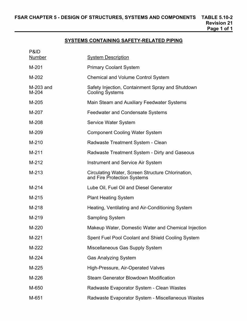
FSAR CHAPTER 5 - DESIGN OF STRUCTURES, SYSTEMS AND COMPONENTS TABLE 5.10-2 Revision 21 Page 1 of 1 SYSTEMS CONTAINING SAFETY-RELATED PIPING
P&ID Number System Description M-201 Primary Coolant System M-202 Chemical and Volume Control System M-203 and Safety Injection, Containment Spray and Shutdown M-204 Cooling Systems M-205 Main Steam and Auxiliary Feedwater Systems M-207 Feedwater and Condensate Systems M-208 Service Water System M-209 Component Cooling Water System M-210 Radwaste Treatment System - Clean M-211 Radwaste Treatment System - Dirty and Gaseous M-212 Instrument and Service Air System M-213 Circulating Water, Screen Structure Chlorination,
and Fire Protection Systems M-214 Lube Oil, Fuel Oil and Diesel Generator M-215 Plant Heating System M-218 Heating, Ventilating and Air-Conditioning System M-219 Sampling System M-220 Makeup Water, Domestic Water and Chemical Injection M-221 Spent Fuel Pool Coolant and Shield Cooling System M-222 Miscellaneous Gas Supply System M-224 Gas Analyzing System M-225 High-Pressure, Air-Operated Valves M-226 Steam Generator Blowdown Modification M-650 Radwaste Evaporator System - Clean Wastes M-651 Radwaste Evaporator System - Miscellaneous Wastes