Embed Size (px)
Citation preview

1
PALLAS: A Portable Asteroid Lift and Lock Aggregate System
Charlotte J. Kiang1, Jeffrey L. Ly2, Eric W. Berg3, Priscilla N. Cancar4, Hannah R. Rudin5 and Ana Diaz Artiles6
Cornell University, Ithaca, New York, 14850
ABSTRACT
The National Aeronautics and Space Administration (NASA) is currently developing a robotic mission to visit a near-Earth asteroid (NEA) and redirect it into lunar orbit. Once this mission is complete, NASA plans to send a manned mission to the same NEA so that astronauts can explore it and return to Earth with samples from the NEA’s surface. Doing so will require a new set of extravehicular activity (EVA) tools, as existing surface sampling tools were designed during the Apollo program for use in a lunar gravity environment, in contrast to the microgravity environment presented by a NEA. Among the tools required for NEA exploration is a float sample grabber, which will allow astronauts to capture and store loose rock samples from a NEA’s surface without cross-contamination between collection sites. This paper describes the design, prototyping, fabrication, and testing processes for a human-operated tool for NEA float sample grabbing. Details are also given on the team’s efforts to use the tool development process to inspire the next generation of engineers and scientists through a comprehensive outreach plan. Finally, qualitative and quantitative data obtained from human trials on the ground and at the NBL are presented and discussed.
Nomenclature AIAA = American Institute of Aeronautics and Astronautics ARM = Asteroid Redirect Mission CAD = Computer-aided design COTS = Commercial off-the-shelf EAMD = Exploration Analogs and Mission Development EVA = Extravehicular Activity EYES = Encouraging Young Engineers and Scientists ISS = International Space Station JSC = Johnson Space Center LEO = Low-Earth orbit MDRS = Mars Desert Research Station NASA = National Aeronautics and Space Adminsitration NBL = Neutral Buoyancy Laboratory NEEMO = NASA Extreme Environment Mission Operations NEA = Near-Earth asteroid NExT = Neutral Buoyancy Experiment Design Teams PALLAS = Portable Asteroid Lift and Lock Aggregate System PETG = Polyethylene terephthalate SLS = Space Launch System STEM = Science, technology, engineering and mathematics
1 Graduate Student, Department of Biological and Environmental Engineering. AIAA Student Member. 2 Graduate Student, Department of Biological and Environmental Engineering. 2 Graduate Student, Department of Biological and Environmental Engineering. 3 Undergraduate Student, Department of Electrical and Computer Engineering. 4 Undergraduate Student, Department of Information Science. 5 Undergraduate Student, Department of Mechanical and Aerospace Engineering. 6 Lecturer and Research Associate, Department of Mechanical and Aerospace Engineering. AIAA Member.

2
I. Introduction ASA’s recently-released “Journey to Mars” roadmap outlines the intermediate steps necessary to advance the United States’ human spaceflight program beyond low earth orbit (LEO) in pursuit of the eventual goal of a
human journey to Mars.1 While the commercial space industry works hard to maintain and resupply the International Space Station (ISS) via the Commercial Crew and Cargo programs, the agency turns its eye towards the Asteroid Redirect Mission (ARM) in the Journey’s “proving ground,” wherein astronauts will use the Space Launch System (SLS) and Orion capsule to explore a near-Earth asteroid (NEA) that has previously been moved into Lunar orbit by a robotic precursor mission. Maximization of productivity during a manned ARM depends on the existence of ergonomically designed, human-operated devices for asteroid sampling.
Whereas NASA’s existing ground and rock sampling tools were designed during the Apollo era for use in a lunar gravity environment, tools for NEA missions must be usable in microgravity.2 Thus, there is currently a technological gap that NASA must bridge in order to conduct its manned NEA mission. To this end, NASA is soliciting proposals from university students through its Micro-g Neutral Buoyancy Experiment Design Teams (NExT) program on the design, fabrication, and testing of tools for asteroid rendezvous and surface sampling. Teams selected by NASA as finalists in the competition were given the opportunity to test their physical prototypes at the Johnson Space Center’s (JSC’s) Neutral Buoyancy Laboratory (NBL) in spring 2016. Thus, while tools should ultimately be designed for use in space, the prototypes must be compatible with a high-pressure chlorine water environment. The Micro-g NeXT program currently offers 6 design challenges, including one for a float sample grabber that must be able to collect and store up to three different NEA float samples without cross-contamination between sites.3
In response to the float sample grabber challenge, the Cornell Microgravity Research Team has designed a Portable Asteroid Lift and Lock Aggregate System (PALLAS) consisting of an aluminum body with 3 foldable extension arms each equipped with a collection pod. The device includes a one-handed actuator for sample grabbing, and captured samples are stored securely in the three independent pods. PALLAS functions completely on manual power, and is extremely portable, as it is able to fit within an 8” x 8” x 18” box. It has a total weight of less than 8 pounds, in accordance with NASA’s requirements.3
The team believes that the combination of machining and additive manufacturing techniques used to fabricate PALLAS represents the perfect balance between cost-effectiveness and adaptability. As the team saw during the manufacturing process, the use of machined aluminum for the majority of the assembly helped minimize the total system cost while mainting high structural integrity. 3D printing was used to make the parts with low stress and load requirements to allow for rapid iteration, manufacturing, modification, and inexpensive production. The pods’ complex geometry and translucent material property was possible via 3D printing using a translucent filament.
II. Challenge Overview Participants in NASA’s Micro-g NExT float sample grabber challenge were given a list of requirements using which to design their devices. Each of these requirements, along with how PALLAS satisfies it, is shown in Table I.
Table I: Micro-g NExT Float Sample Grabber Challenge Requirements
Requirement Compliance The device (all parts) shall fit within an 8in x 8in x 18in volume.
PALLAS has been designed to fit within the given constraints, as shown in Section III.
The device (all parts) shall have a dry weight less than 15 lbs.
The tool weighs less than 8 lbs, which falls far under the given limit.
The device shall be compatible with a chlorine water environment.
The tool is constructed using only plastics, aluminum and rubber sealant, all of which are pre-approved for short-term submersible use in the NBL.
The device shall be capture and contain at least one (1) float rock per sample site.
The tool includes three (3) pods, each of which can capture and contain a float rock from a given site.
The device shall provide for collection of samples from three (3) separate sites without cross
The tool’s design includes three discrete pods, each of which can collect one float sample. The pods are held
N

3
contamination between sites. firmly in the closed position when not in use to prevent contamination.
The device shall provide for storage of samples independent of one another in order to prevent cross contamination during transportation.
Samples will be stored securely in individual 3D-printed pods once collected. The pod lips are coated in rubber sealant to ensure that they stay firmly closed unless actuated by the operator.
The device shall enable visual verification that a sample has been obtained.
The pods are constructed using translucent plastic to enable visual verification that a sample has been obtained.
The device shall be capable of obtaining a sample between 1 and 3 inch diameter.
The pods have been designed to accommodate up to a 3” diameter sphere, the largest volume possible for an object meeting the stated requirements.
The capturing task shall be accomplished via one-handed operation.
The capturing mechanism can be actuated using a simple squeezing motion that employs only one hand.
The device shall use only manual power. The device is actuated using a purely mechanical system. The design does not include electronics, pneumatics or hydraulics.
The device may have multiple parts that can attach and detach.
Not applicable. (The final device is contained within one structure.)
The device shall allow ambidextrous operation. The device actuator (a.k.a. handle) is ergonomically designed and favors neither right nor left handed operators.
The device shall have a tether attachment point 1” in diameter
A 1” tether loop is attached to the tool’s handle to allow restraint by the operator.
Students were asked to form teams to design a device capable of meeting these requirements. These teams were then invited to submit their designs for NASA’s review during the fall semester. As a result of this review, the teams whose designs were judged to have the most merit were invited to build hardware prototypes of their designs and to test these prototypes at the NBL at the end of the spring semester. In addition to hardware development and testing, teams were also required to share their progress and scientific findings with the educational community through a comprehensive outreach plan. Teams were given a small amount of initial funding from NASA to complete these tasks, but were responsible for raising the majority of funds for their hardware, travel and outreach activities.

4
Figure 1. Schematic labeling PALLAS’ significant components.
III. Technical Design The team’s top priority in the design of PALLAS was to keep the device simple, so as to minimize the chances of failure and need for spare parts, while complying with the challenge requirements. The final design contains no gears or small parts that could be snagged by particulates as well as no additional parts that must be attached or removed. The system is all-in-one requiring no extra components to be assembled during operation. Figure 1 shows a CAD rendering of the complete system, which consists of a main arm and three extendable arms, each of which has a pod fastened to its end. The system’s mechanical design allows one of these pod-carrying arms to be extended at any given time. Arms that are not extended are folded back and held in place by the extension clip attached to the main arm. For arms that are extended, the shifter on the main arm can be used to lock and engage the pod for actuation. When the extension arm is first extended, the spring loaded push rod will automatically lock the main arm, after which the user must move the shifter into the engaged position before the pod can be actuated. The pod scoops are spring loaded so as to automatically retract when not being acutated, ensuring samples are tightly secured at all times.
In designing PALLAS, the team sought to minimize the number of small parts involved in the system, yielding the foldable arm design and push rod actuation system. The details of the design are described below.
Shifter — The device’s shifter is used to lock and engage one arm at a time in the extended position (see Figure 1). The shifter mechanism ensures that the user must consciously engage and disengage the actuating system before and after use. Once the user is finished collecting a sample, he/she must disengage the shifter and retract the locking mechanism in order to fold back the extension arm. Pods on arms that have not been locked cannot be actuated and therefore opened. This step provides extra security to pods in the retracted position. Furthermore, the lock/engage lever ensures that the extension arm will remain extended throughout the duration of operation and will not retract unexpectedly. Figure 2 shows the setup of the handle. The tool’s shifter is located directly below the actuator and hand grip.
Figure 2. Close-up of hand grip, actuation system and shifter lever.

5
Tool Grip— The designed tool includes an ergonomically designed handle for ambidextrous use by human operators as shown in Figure 3. Taking inspiration from everyday objects such as cooking utensils and umbrellas, PALLAS team members created a handheld actuation system centered around a cylindrical base. The handle grip’s dimensions were carefully selected to accommodate operators donning ski or space gloves, in accordance with NASA’s Space Flight Human Standards.4 The grip was designed to ensure full control of the tool while minimizing stress on the user’s hand and arm. Although the team initially considered the trigger-handle grip used in many claw grabbing tools, a cylindrical design was chosen to give the user better control of the movement of the tool using his/her wrist. The grip ensures the tool will not pivot in the user’s hand. The grip is positioned coaxially with the rest of the tool, aiding the user in aiming the pods for rock collection and eliminating unecesary torques on the hand.
Actuator— The acuator controls the opening and closing of the pods through a mechanical push rod system. The actuator is spring assisted as shown in Figure 4 to reduce the amount of force required by the user’s hand. It is comfortably positioned in the center of the handle and can be easily squeezed with either hand. The actuator can only be pressed when the shifter is in the engaged position. The acuator must be pressed down fully in order to fully open the pods. Once released, the spring loaded pods will close and the actuator will be returned to its uncompressed position.
The operator’s ability to open and close pods only exists when pods are positioned on arms in the “extended” position. This prevents operators from losing samples due to accidental actuation of the jaw mechanism. Triple Hinge— The triple hinge is a custom-designed part used to join the extension arms to the main arm as shown in Figure 5. Off-the-shelf hinges were to weak to bear the loads experienced at the joints, not the right dimensions, and would need to be severly modified to fit in the design. The triple hinge facilitates the folding movement of each arm and ensures each arm is aligned when extended. The triple hinge is made of aluminum to able to bear large stresses and torques from the arms. Because the single part receives all three arms as opposed to having three separate hinges, the reduces the total number of parts.
Figure 3. Handle grip and actuator
Figure 4. Handle (without grip), actuator, and internal shock system.
Figure 5. Triple hinge joining extension arms to main arm.

6
Pods—The pods are 3D-printed using translucent plastic to enable visual verification that samples have been obtained. As shown in Figure 3, holes are included in the structural design to allow the flow of air and water through the system in accordance with NBL engineering and safety requirements. The holes in the pods reduce the drag on the scoops, decreasing the mechanical force that must be exerted by the user to open the scoops. The holes also allow for quicker retraction of the scoops to secure the samples faster. (If the tool were to be used in space, these holes would likely be eliminated from the design, which can be done easily by re-printing the pods.) While the team initially considered a spherical shape for the pods, it was determined that the curved lip would render capturing a float sample difficult unless the sample was directly centered within the capturing sphere. To increase chances of capturing the sample, the team designed a pod with a flat-ended lip to increase the tool’s tolerance for lateral error. Using its angular geometry, the leading lip guides the sample into the pod upon closure. The lips of each pod will be topped with a rubber adhesive sealant to ensure no dust particulates escape from the sample collection by movement or vibration during storage or transport.
IV. Human Factors Analysis As one of the team’s major goals was to create a tool that optimizes human productivity in space, the team took a human-centered approach to the design of PALLAS. Special consideration was given to anthropometry and biomechanics in choosing the tool’s dimensions. Additionally, the tool was designed with an intuitive human interface in order to minimize the mental workload imposed on its operators.
Anthropometry and Biomechanics— Recognizing the need for the device to accommodate operators wearing pressurized space suit gloves, the team consulted NASA’s Man-Systems Integration Standards to determine the optimal dimensions for PALLAS’ actuator and grip. The anthropometry and biomechanics documentation available from NASA states that EVA tools and external handles on space vehicles must have handles no less than 15.2 cm long, 5.75 cm deep and 3.5 cm wide (approximately 6” x 2.25” x 1.4”).4 Thus, the tool’s handle is 7” long and has a 1.5” diameter.
Astronauts had previously described the force required to flex one’s fingers while wearing a space glove as akin to that needed to “squeez[e] a tennis ball.”6 To mitigate the additional force needed to activate the device, efforts were made during the design process to minimize the amount of force needed to actuate PALLAS, as well as make the actuating motion as simple as possible.6 A shock system was installed inside the handle to automatically lock the arm, elimanting the need for the user to perform that operation. The internal shock system also reduces the force that must be exerted by the user to actuate the pods. The only required motion is therefore a light squeeze with either the left or right hand. (The risk of accidental actuation is minimized by the shifter lever system described in section 2 of this paper.)
Figure 6. Extension arm with pod scoops assembled
Figure 8. Illustration of Gestalt’s principle of proximity.
Figure 7. Illustration of Gestalt’s principle of proximity.

7
Attention and Workload— Since the manned portion of the ARM will be a human exploration mission to a body that has never previously been explored by humans, it will be necessary for astronauts on this mission to maintain a high level of situational awareness while performing EVAs. Maximizing situational awareness requires that operators reserve an adequate amount of mental resources for perceiving and comprehending their environments, as well as project the status of their environments in the near future.7 This necessitates that the tasks that operators are being asked to perform not be overly complex. To accommodate this requirement, team members ensured that the overall process required to use PALLAS was composed of only a few simple and distinct sub-tasks. At no point during the device’s use is the operator required to perform two tasks simultaneously, or to execute a task that requires knowledge that cannot be visually obtained from the device. Mental workload is further minimized by PALLAS’ intuitive visual interface. In accordance with Gestalt grouping principles, humans have a natural tendency to form mental associations between objects if they look similar and are positioned in close physical proximity to each other.8 (See Figures 7 and 8.) Thus, the positioning of PALLAS’ pods during actuation and storage makes it immediately obvious to operators which pod is in the engaged position, as opposed to locked for future use or to contain samples that have already been collected. Figure 9 shows a CAD rendering of the tool’s 3 pods when all of them contain samples and their corresponding arms are locked in the retracted position. The use of translucent material for pod construction allows operators to distinguish between full and empty pods immediately upon sight, eliminating the need to recall this information from memory. Thus, while the mental workload imposed by PALLAS on its operators were confirmed through tests with human subjects at NBL. As the team expected during testing, with training and familiarization with the device, operators should be able to actuate PALLAS while maintaining attuned to their surroundings. Since implementing a situational awareness test would be difficult during initial ground tests or during testing week at the NBL, the team plans to propose further trials of the device in terrestrial space analog environments, as detailed in this paper’s discussion and conclusion.
V. Manufacturing The team was selected as a finalist in NASA’s 2016 Micro-g NExT competition and completed fabrication and testing of a PALLAS prototype during the spring 2016 semester. The team’s manufacturing plan is detailed below.
Material Selection— A complete list of materials needed to construct PALLAS is shown in Table II. All materials were selected from the NBL’s list of pre-approved materials for use in chlorine water environments. The main arm, arm extensions, and push rods were machined from purchased aluminum, while plastic components such as the pods and extension arm clip were made using translucent, high-strength polylactic acid (PLA) material. Commercial off-the-shelf (COTS) shocks were used for the pod’s mechanical loading system. NBL-approved Loctite Epoxy adhesive was used to join fix certain parts together. GE Silicone Caulk was used to protect the user from any sharp edges.
Figure 9. View of PALLAS in its folded configuration with all pods secured.
Figure 10. View of PALLAS in its extended configuration with one pod engaged.

8
Table II: List of materials needed for PALLAS and their estimated costs.
Materials Total Cost (USD)
PLA Orange and Clear 1.75mm Filament $51.90
Multipurpose 6061 Aluminum Tube 1" x 0.25" x 0.5"
$36.95
Multipurpose 6061 Aluminum Rod 0.5" $14.00
Multipurpose 6061 Aluminum Tube 1.5" x 0.25" x 1"
$19.07
Multipurpose 6061 Aluminum Rectangular Bar 1" x 1"
$28.81
Ribbed Round Grip with Finger Grooves, Fits 1-1/2" OD, Black (pack of 6)
$12.86
Loctite Epoxy Adhesive $13.71
HPI Savage XS Flux Mini Shock Set (Pack of 4) $69.08
Multipurpose 6061 Aluminum Rod 0.125" $7.09
GE Silicone II 2.8 oz. Caulk 100% $3.98
Hardware (Bolts, Screws and Nuts) $4.98
Total $262.45
Fabrication— The main arm and arm extensions were machine-cut to the appropriate length and lathed to an appropriate inner diameter for the design, as the interior needed to accommodate the push rods for actuation. The push rods themselves were cut to the desired lengths from the purchased aluminum. The rods were rounded off at the ends using a lathe to allow for better contact with the pod lips. The push rods had to meet very tight standards of tolerance in order to allow for smooth device operation. The main arm and extension rods were reamed with a .501” ream. The push rods were then sanded down to .499” and polished with scotch brite. These tolerances were further adjusted later in the prototyping process to allow for lubrication and accommodate for inaccuracies in the folding arm positioning, but still remained within the same general range of dimensions. All push rods were secured into their corresponding arms with a pin and slot mechanism to limit the movement of the rods and prevent them from falling out. The slots were machined into the arms using a mill and pins were made using 1/8” aluminum. Custom hinges were milled from aluminum to allow each extension arm to pivot in the triple hinge. Next the triple hinge was machined using a rotating vice on the mill. The extension arm clip was 3D-printed from the purchased PLA filament material using the additive manufacturing facilities in Cornell’s rapid prototyping facility. The pods were 3D-printed in the same facility and using the same material. Holes were included in each pod to allow the free flow of air and water through the component during operation. The PLA plastic filament proved to be rigid enough to prevent severe deformation or flexing. The material was also strong enough to sustain impact when interfacing with rock samples.
The purchased shocks were then mounted to the pods using the built in mounting horns and shock mounts were positioned around the extension arm. Some parts, such as the shifter and the shock mounts were originally designed to be manufactured out of aluminum, but after reconsideration the team decided to 3D print these parts to allow for faster iteration and modification. The team determined that 3D printing was an appropriate manufacturing technique for these parts because at no point during device operation would the parts in question experience high stresses. Once all necessary components were machined or printed, the team assembled all of the parts into the final product. Orginally the hinges on each extension arm as well as the hinges on each pod were glued using Loctite epoxy, but
9
after these bonds failed after repeated use of the device, the team decided to secure all previously glued parts with machine bolts and nuts. The triple hinge and its three receiving hinges were thus bolted to their respective arms. In addition, the pod hinges were secured using bolts and nuts as well.
VI. Design Validation
The team performed extensive testing throughout the fabrication process to ensure strength and functionality of PALLAS prior to arrival at the NBL in June 2016. The three identified potential points of failure were the pods shocks, main arm flexion under angular motion, and the arm extension clip, so special attention was given to these components during testing. In addition, tests were conducted to ensure the design is ergonomic for human users under several environmental conditions.
Pod Validation— Testing was conducted to ensure proper spring loading and to determine the spring constant necessary to overcome the viscosity of water without the pods opening unintentionally during operation. The sample pod arms were submerged in water in a controlled lab environment and observed to determine whether pod jaws open without human actuation. The handle (i.e. actuator) is the subsystem of PALLAS most prone to failure as it houses the least structurally sound pieces of metal. The hinges are the system’s most mechanically intricate parts and were thus most likely to experience problems during operation. However, the team did not observe any such failure during component testing and thus determined that the design was robust enough to withstand the environment of the NBL.
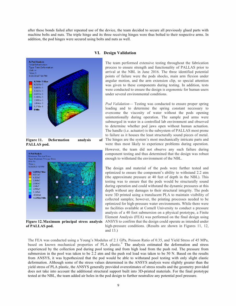
The design and material of the pods were further tested and optimized to ensure the component’s ability to withstand 2.2 atm (the approximate pressure at 40 feet of depth in the NBL). This testing was to ensure that the pods would be structurally sound during operation and could withstand the dynamic pressures at this depth without any damages to their structural integrity. The pods were 3D printed using a translucent PLA to maintain visibility of collected samples; however, the printing processes needed to be optimized for high-pressure water environments. While there were no facilities available at Cornell University to conduct a pressure analysis of a 40 foot submersion on a physical prototype, a Finite Element Analysis (FEA) was performed on the final design using ANSYS to confirm that the design could operate as intended under high-pressure conditions. (Results are shown in Figures 11, 12, and 13.)
The FEA was conducted using a Young’s Modulus of 2.1 GPa, Poisson Ratio of 0.35, and Yield Stress of 45 MPa, based on known mechanical properties of PLA plastic.9 The analysis estimated the deformation and stress experienced by the collection pod during pool testing and from high load from the push rod. The pressure from submersion in the pool was taken to be 2.2 atm and the push rod load was taken to be 50 N. Based on the results from ANSYS, it was hypothesized that the pod would be able to withstand pool testing with only slight elastic deformation. Although some of the stress values determined in the ANSYS analysis were slightly greater than the yield stress of PLA plastic, the ANSYS generally provided overestimates of stress results and the geometry provided does not take into account the additional structural support built into 3D-printed materials. For the final prototype tested at the NBL, the team added air holes in the pod design to further neutralize any potential pool pressure.
Figure 11. Deformation analysis of PALLAS pod.
Figure 12. Maximum principal stress analysis of PALLAS pod.
10
Main Arm Flexion Validation— Stress tests were performed on the aluminum to determine the degree of flexion under angular motions. To conduct these tests, a team member submerged the rod assembly in water and performed a series of angular movements in both the z and y directions to ensure that the assembly was structurally sound. A flex in the main arm would result in failure of the actuation system, so these tests were necessary to ensure successful operation in a high-pressure water environment. No failures were experienced during the tests, so the team concluded that the main arm design was structurally sound.
Arm Extension Clip Validation— The arm extension clip was tested under normal operating conditions in water to ensure that arms could remain retracted when not in use, but were not overly difficult to extend by human operators. The assembly was tested under water in a controlled laboratory environment using a series of lateral and angular motions to demonstrate the effect of drag and the ability of the clip to resist the force of water’s viscosity
while still allowing arms to be extended and retracted using a human applied force. The team found that its original design resulted in a robust and ergonomically efficient system, so no further iterations were made on the arm extension clip design.
Ground Testing and Data Analysis— Ground measurements will be taken in a normal 1G terrestrial environment for an initial human factors assessment of PALLAS. The ergonomics of the hand grip were tested on 6 human subjects, who were randomly selected from the Cornell community. All subjects met the basic physical criteria for eligibility as a NASA astronaut, and were evenly distributed across genders (3 male and 3 female; ages 18-34).
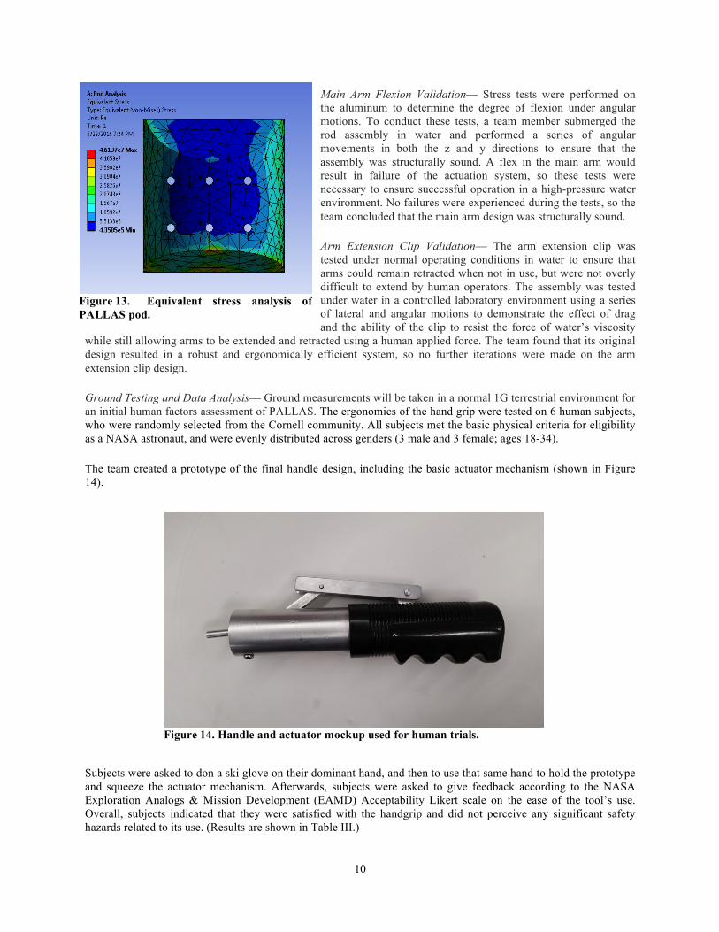
The team created a prototype of the final handle design, including the basic actuator mechanism (shown in Figure 14).
Subjects were asked to don a ski glove on their dominant hand, and then to use that same hand to hold the prototype and squeeze the actuator mechanism. Afterwards, subjects were asked to give feedback according to the NASA Exploration Analogs & Mission Development (EAMD) Acceptability Likert scale on the ease of the tool’s use. Overall, subjects indicated that they were satisfied with the handgrip and did not perceive any significant safety hazards related to its use. (Results are shown in Table III.)
Figure 14. Handle and actuator mockup used for human trials.
Figure 13. Equivalent stress analysis of PALLAS pod.

11
Table III: Results and Statistical Analysis of Human Trials for Actuator Criteria Mean Rating Standard Deviation
Handle/grip is comfortable to hold 1.33 0.52
Actuator is easy to squeeze for activation 2.33 1.51 System has no pinch points, protrusions, or other perceived hazards 1.17 0.41
The final validation of the design before testing week at JSC took place at the Cornell University pool in Helen Newman Hall. A human subject was asked to use the finalized unit underwater to collect samples while donning ski-gloves. Sample objects with a diameter between 1” and 3” were used to simulate rock float samples for collection. While the pool in Helen Newman is not as deep as the NBL, additional depth was not anticipated to be a significant factor in the design, per the FEA. The successful completion of this testing demonstrated the operability of PALLAS in a chlorinated water environment.
VII. Test Week Results
After successfully completing all ground tests for design validation, the team brought its prototype down to the NBL for final validation. The primary test objectives were as follows:
1. Ensure that pods can be fully closed and opened repeatedly, 2. Ensure that arms can be switched easily, 3. Ensure that arms remain locked in extended position, 4. Ensure that arms remain folded in extension clip when not in use, 5. Confirm that pods can collect and trap float samples, 6. Ensure that full pods can be distinguished from empty pods.
The team trained the NBL divers to use PALLAS before beginning the dive sequence. Following training, the divers were presented with the following general mission summary:
1. Begin with PALLAS in folded configuration, 2. Perform preliminary tests explained in NASA’s NBL Test Plan, 3. Approach rock sample site, 4. Press actuator to open scoop and capture float sample, 5. Stow arm away and engage next arm, 6. Collect two more samples, 7. Return to folded configuration and resurface to pool deck.
Divers were then asked perform a series of tests underwater to determine the ease of the device’s use while collecting samples. The nominal procedure for capturing a float sample using PALLAS is as follows:
1. Pull back shifter to disengage main rod, 2. Fold extension arm into place and release shifter, 3. Move shifter into actuating mode, 4. Press actuator to open scoops, 5. Capture rock sample, 6. Pull back shifter to disengage main rod, 7. Fold occupied extension arm back and snap into extension clip.
After mastering the use of the device, divers commenced with underwater testing, where they were given 5 tests to perform. Details on the specific tests performed during the dive are given in Table IV.

12
Table IV: NBL Tests Test Objective
Float Sample Test Collect float samples using Pod 1. Bed Rock Test Collect samples in the bed of rocks with pod 1. (Discard
following collection.) Rapid Collect Test Collect samples and deposit them quickly into a storage
box. Pod Jam Test Pods 2 and 3 were intentionally configured to be
difficult to open; the purpose of the test is to see whether or not the operations are still successful in a jamming scenario.
Full Operations Test Collect samples with each of the 3 pods. Switch between pods 1, 2, and 3.
All tests were completed successfully by divers, with the only minor difficulty being the resistance of pods to actuate on a few occasions, and trouble getting the pods to close after opening them for collection. However, these hitches occurred infrequently, and overall did not seem to interfere with the overall goals of the test. After testing was complete, the dive team appeared to be in concurrence that PALLAS was a functional and ergonomically designed device. Table V shows the aggregated qualitative feedback from the dive team, organized by category.
Table V: Qualitative Feedback on PALLAS from NBL Dive Team Category Feedback
Overall design • All-in-one design was ergonomic and saved time since minimal effort was needed to swap between pods
• Because of all-in-one design, there were less parts to tether, and less energy to exert to swap between pods
• Tether location below handle was helpful • Overall, design was simple, practical and intuitive
Functionality (usability) • Easy to aim and grab a float sample • Linear line of sight of PALLAS design was
extremely helpful in obtaining samples • When trying to scoop rocks from the rock bed, the
pods remained intact and were able to retain collected samples
• PALLAS had a good weight balance between the main handle and 3 extendable arms
• Rotating design of the tether loop made moving underwater with the device an easy task
Ideas for improvement • Extend handle grip to full length of the main handle • Find an adhesive to use other than epoxy glue (epoxy
did not adhere to the smooth surface of the metal and did not hold up well against the forces exerted on it by the shocks)
• Make locking of arms independent of actuation Criticisms • Scoops did not always fully close on their own
• Divers occasionally experienced resistance to actuation, despite following procedures
Other comments • PALLAS was one of the dive team’s favorite devices to use due to the simple, all-in-one design

13
In addition to the comments listed above, quantitative feedback was solicited from the dive team according to the EAMD Acceptability Likert scale. The results of the survey are shown in Table VI, and a detailed breakdown of the EAMD Acceptability Likert scale is shown in Table VII.
Table VI: Ergonomic Assessment of PALLAS by NBL Dive Team
Table VII: EAMD Acceptability Likert Scale
VIII. Discussion The results clearly indicate that the largest area for improvement is the ease of actuation, and thus, this will be a key focus for the team in future iterations of the PALLAS design. One proposed solution for ease of actuation is making the locking portion of the extension arms independent of the actuation movement. This would allow the main push rod to have a smaller diameter at the end, reducing the friction incured on the push rod by the extension arm’s inner wall. With a separate locking mechanism, the arms would clip into place once extended, and then a smaller diameter at the end of the main push rod would push the extension arm push rods and open the pods. This solution minimizes friction and therefore eases actuation and lowers the required input force by the user. The team will also carefully consider all other suggestions from the dive team for improvement, such as the use of a different glue for the shock mounts and extension of the hand grip to cover the whole main arm. The team plans to extend the handle grip to encompass the entire site of actuation so the user’s hand is always on the grip whether the tool is being actuated or merely held. Several other improvements were suggested to expand the capabilities of the tool. One engineer suggested making the pods easily removeable and swappable so that more than three samples can be collected. If the tool included swappable pods, an astronaut could collect three samples, detach the secured sample pods and store them, reattach new unused pods, and continue sample collection. Another suggestion was to make the entire extension arm replaceable, to allow for a quick repair as well as the mounting of an entirely different tool. The main arm and acutation system could serve as a base platform for a variety of tools. A different tool such as a rock chipping tool could be attached instead of the current float sample extension arm. Using the main arm and actuation system to accommodate for a variety of tool extensions would make the tool multipurpose. One improvement necessary to make the tool space-ready would be to use a different material for all 3D printed parts. PLA plastic is not able to withstand the extreme temperatures experienced in space. The parts could withstand the conditions of space if made out of steel instead of plastic, since steel has a low coefficient of thermal expansion and is thus unlikely to deform even in volatile environments. While such a change would dramatically increase the mass of PALLAS, this increase in mass is not expected to affect operations, since the tool would be weightless in space regardless of its mass on Earth. In addition to this change in material, the pods would no longer be printed with holes in them, as these holes were included to allow water to flow in and out of the pods during NBL testing. Thus, the pods would be completely sealed after sample collection, and would not be re-opened until the whole
Criteria Rating Ease of shifter 2 Ease of actuation 4 Visibility of pods 2 Shifting between arms 2 Maintaining sample 2 Locking arms 1 Arms staying in clip 1

14
device was returned to the spacecraft from which the EVA was performed. This design change, in turn, would necessitate further structural analysis and testing for the pods, as they would need to be strong enough to withstand the pressure change from the vacuum of space to the spacecraft’s pressurized environment without imploding or damaging the contained samples. Ultimately, this change would maximize the scientific value of the tool, as maintaining the asteroid sample in a vacuum isolates it from any organic bacteria that could be present in the pressurized cabin of the spacecraft, preserving the sample’s integrity. Once returned to earth, the sample pods could then be depressurized in a controlled environment in a lab for further examination.
IX. Outreach Plan A key goal for the PALLAS team members, in addition to prototyping and constructing a device for the Micro-g NExT challenge, was to also share the experience of building astronautic tools with others and to encourage more widespread involvement with science and engineering through educational outreach. When organizing outreach events, the Cornell Microgravity Research Team’s overarching goal was to inspire the next generation of space engineers and explorers. The team reached out to students of all ages and stages within the educational community, but particularly focused on students aged 6-17, as inspiration to pursue a STEM major or career would likely have the greatest effect on these students. During all outreach efforts, the team tried to maintain an inclusive experience to those who where not familiar with the space-engineering field and where not exposed to astronautics. The team developed an inclusive outreach strategy that included both informational presentations and hands-on demonstrations of space science and engineering. The details of the team’s outreach plan are given below. Website and Social Media— The team created a website (http://www.cu-microg.com) and Twitter account (@CU_MicroG) to publicize its efforts. Both online presences were maintained throughout the year as the team advanced through the design, fabrication and testing process, and eventually to test week at JSC. The website contains information about all team members and project advisors, as well as an outline of the basic scientific goals and technical approach to the team’s experiment, while the Twitter account served as a real-time mini-blog reflecting the team’s daily progress. Newspaper highlights— PALLAS was featured in Cornell’s campus wide newspaper, the Cornell Daily Sun. (http://cornellsun.com/2016/03/22/student-team-crafts-tools-to-collect-rocks-from-asteroids/) The article help spread the word about the PALLAS team and NASA’s outreach efforts to inspire and encourage readers on and off campus. This story covered the team’s history, mission statement, and involvement with NASA. Local Ithaca Community Sciencenter— The Cornell University student body has a history of involvement with several STEM outreach initiatives in the Ithaca and New York City areas, providing pre-established venues for the PALLAS team’s local outreach efforts. Ithaca’s Sciencenter Museum is a frequent collaborator on Cornell’s outreach programs, and was able to host the Cornell Microgravity Research Team for a public forum on EVA and astronaut tool development in May 2016. The talk was well attended, and appeared to re-ignite some of the local community’s interest in the human space program. School Visits— The team sought to share its experiences with several K-12 schools located in the Ithaca area. However, in addition to this involvement with local schools, team members tried to maximize the reach of their efforts by contacting their alma maters to arrange visits regarding the project and test week. The schools that the team has engaged with so far include: • Dana Hall School (Wellesley, MA) • Horace Mann School (Bronx, NY) • St. Louis University High School (St. Louis, MO) The geographical diversity of PALLAS team members ensured that project outreach will extend far beyond the Ithaca area. Special efforts were also made to include all-female institutions (such as the Dana Hall School) among the planned school visits in order to increase exposure of young women to space science and engineering. At the time of writing for this report, the team still plans to conduct additional visits to schools in Virginia and New York. Completed activities, such as the one conducted with Fall Creek Elementary in Ithaca, included a full class period

15
dedicated to talking to students about PALLAS and NASA’s Micro-g NExT program, as well as completion of a mini rocket-building challenge. The goal of these visits was to demonstrate to students that the academic research experience encompasses much more than just sitting on a lab bench, and that opportunities to work with NASA on space technology projects are well within reach to students who work hard, pursue technical coursework, and show initiative outside of their classes. In demonstrating this, the team hoped to inspire and galvanize the next generation of science and engineering talent. At all completed school visits, the student body appeared enthused by the team’s work, and several students sent follow-up emails to team members to inquire about ways they could become involved with NASA. Cornell University— The team also made presentations to other Cornell student organizations through the school’s existing infrastructure for on-campus outreach. By ensuring that all potentially interested students were aware of the space technology research and development opportunities available to them, the team hopes that Cornell students will continue the tradition of NASA engagement and microgravity research long after Cornell’s 2016 Micro-g NeXT experiment has completed its testing. The Cornell Microgravity Research Team has been incorporated and funded as an official Cornell University club, and as a stretch goal, the team is attempting to obtain status as a formal engineering project team that submits proposals to NASA’s Microgravity University program each academic year. Several students have expressed in joining the team for the 2016-17 year, and the team intends to begin working on another proposal for the competition in the fall. Looking into future, the Cornell Microgravity Research Team hopes to establish itself as an official project team that can collaborate with NASA on various projects and challenges in the years to come. Currently, the team is a group of 5; however, the team is in the process of recruiting new members for the upcoming school year and expanding itself into a larger organization.
X. Conclusion This report details the design and the planned prototyping, fabrication and testing for PALLAS, a human-operated asteroid float sample grabber tool. PALLAS successfully satisfied its designed purpose to collect float samples without cross contamination. Based on the results obtained from testing at the NBL, the team believes that the the PALLAS design merits further consideration as a tool for human space missions, and plans to continue iterating on the design for future Micro-g NExT competitions. The team believes that its tool’s design is capable of truly being used as an EVA tool used by NASA austronouts in space and hopes that NASA EVA engineers are able to use this report to recreate the tool and conduct further testing and research necceesary to prepare the tool for use in space. In effort to determine the effect that using PALLAS has on operators’ situational awareness, the team also plans to seek future testing opportunities for PALLAS in terrestrial space analog environments including Aquarius Reef Base and the Mars Desert Research Station (MDRS). Crewmembers performing EVAs from these habitats will be experiencing a mental workload similar to that experienced during a real EVA, so they will be able to provide valuable data on their level of situational awareness while using PALLAS. Potential space analog simulation missions on which PALLAS could be tested include Project Poseidon, a proposed 100-day scientific research mission to Aquarius slated for mid-2017, as well as any crew mission during the 2016-2017 field season of MDRS, for which applications will open in mid-2016.10 Over the course of the design and testing process, the team learned the importance of test-driven development to successful hardware system design. While the team was ultimately able to deliver a fully working prototype that passed all ground tests, re-design was necessary on several occasions because the team did not conduct component-wise tests before moving forward with system development. The result of this was unnecessary rework time that the team hopes to reduce in future years. Additionally, the team learned the importance of strong communication and teamwork in accomplishing a large goal. In future years, the team hopes to recruit several more dedicated members who can commit to the task of helping NASA explore the solar system.

16
Acknowledgments The authors thank Dr. Ana Diaz Artiles, faculty advisor to the Cornell Microgravity Research Team, for her mentorship throughout the project, as well as Dr. Steven Squyres for his input on EVA tool ergonomics, and Jessica Tramaglini for her help as the team’s official NASA mentor. Funding for this research was provided by NASA, Bartel’s Co-Sponsorship, Cornell’s Mechanical and Aerospace Engineering Department, Cornell SAFC Funding, and the New York Space Grant Consortium. Finally, the team thanks the NASA Micro-g NExT Team – Katie Livingood, Kelly McCormick, and Trinesha Dixon – for coordinating the entire competition and providing this opportunity.
References 1 “NASA’s Journey to Mars,” NASA, 2014. Retrieved from http://www.nasa.gov/content/nasas-journey-to-mars/. Accessed 1 December 2015.
2 Zimmer, A. K. “Going beyond: Target selection and mission analysis of human exploration missions to Near-Earth Asteroids.” Acta Astronautica, 69 (2011): 1096-1109. 3 “NASA Micro-g NeXT Design Challenges,” NASA, 2015. Retrieved from https://microgravityuniversity.jsc.nasa.gov/theProgram/micro-g-next/index.cfm. Accessed 1 December 2015. 4 “NASA Space Flight Human Standards.” NASA, NASA-STD-3001, 2015. 5 Chappell, S. P. et al. “NEEMO 15: Evaluation of human exploration systems for near-Earth asteroids.” Acta Astronautica, 89 (2013): 166-178. 6 Collins, M. Flying to the Moon: An Astronaut’s Story. Harrisonburg, Virginia: RR Donnelly & Sons, 1976. 7 Endsley, M. R. “Situation Awareness in Aviation Systems.” Handbook of Aviation Human Factors. Ed. Garland, D. J. et al. Mahwah, NJ: Lawrence Erlbaum Associates, 1999. 257-276. 8 Proctor, R.W. and Van Zandt, T. Human Factors in Simple and Complex Systems. Boca Raton, Florida: CRC Press, 2008. 9 “Mechanical Properties of Plastic Materials.” Professional Plastics. Professional Plastics, 2015. 10 “Project Poseidon.” SeaSpace Exploration and Research Society. SeaSpace Exploration and Research Society, 2015. 11 “Pathways to Exploration – Rationales and Approaches for a U.S. Program on Human Space Exploration.” National Research Council of the National Academies. National Academy of Sciences, 2014. 12 Brannan, J. and Bradshaw, H. “Development and Field-Testing of a Prototype Toolkit for Astronaut Planetary Exploration Activities on Moon/Mars.” 49th AIAA Aerospace Sciences Meeting including the New Horizons Forum and Aerospace Exposition, 4-7 January 11, Orlando, Florida. American Institute of Aeronautics and Astronautics (AIAA), 2011. 13 Castillo, T. et al. “Calculating and Mitigating the Risk of a Cut Glove to a Spacewalking Astronaut.” 6th IAASS Conference, 21-23 May 2013, Montreal, Canada. International Association for the Advancement of Space Safety (IAASS), 2013. 14 Gast, M. A. and Moore, S. K. “A Glimpse from the inside of a space suit: What is it really like to train for an EVA?” Acta Astronautica, 68 (2011): 316-325. 15 Gruntz, D. W. Development and Evaluation of a Tool for EVA or Robotic Planetary Sampling. Dissertation. University of Maryland, 2007. 16Hoffman, S. J. “Advanced EVA Capabilities: A Study for NASA’s Revolutionary Aerospace Systems Concept Program.” NASA, April 2004. 17 Kane, R. et al. “Cognitive Assessment in Long-Duration Space Flight.” 82nd Annual Scientific and Human Performance Meeting of the Aerospace Medical Association, 8-12 May 2011, Anchorage, Alaska. Aerospace Medical Association, 2011.

17
18 Marvin, U. B. et al. “Relative proportions and probable sources for rock fragments in the Apollo 12 soil samples.” Proceedings of the Second Lunar Science Conference, 1 (1971): 679-699. 19 McDonald, V. P. et al. “Understanding Skill in EVA Mass Handling – Volume I: Theoretical & Operational Foundations.” NASA, June 1997. 20 McDonald, V. P. et al. “Understanding Skill in EVA Mass Handling – Volume II: Empirical Investigation.” NASA, June 1997.