Embed Size (px)
Citation preview

Installation, use and maintenance, risk assessment manual
Pallet racks Bi-Bloc

Instruction manual • Bi-Bloc1
GENERAL OVERVIEW
General rules for the use of Bi-Bloc storage system
Construction and assembly tolerances
Limits of supply and use
Applicable standards
User’s liabilities
Maximum permissible upright frame loads
Maximum permissible beam loads
List of components
ASSEMBLY STEPS
Installation phases
Tightening torque tables
CORRECT MAINTENANCE GUIDELINES
Scheduled maintenance plan
HAZARD IDENTIFICATION, EVALUATION AND ASSESSMENT
Semi-quality scales
Hazard class ranking
2
3
4
4
4
4
5
8
10
16
17
18
18
Contents

Instruction manual • Bi-Bloc2
General information
GENERAL RULES FOR THE USE OF BI-BLOC STORAGE SYSTEM
UseBi-Bloc racks are made of vertical elements called uprights and by hori-
zontal elements called beams. Both elements have been carefully desig-
ned to store load units. A load unit is made of a pallet and stored goods.
Once racks are fi tted with additional accessories they can take other
kinds of load units, including boxes, cartons etc.
Maximum load and size limitations for each load unit cannot be exce-
eded. Pallets must be suitable for rack usage and must be free of defects
or damages that may result detrimental to load performances. (see ap-
pendix B - FEM 10.2.03). Disposable pallets are not recommended.
Goods must be placed on pallets or containers in a way that ensures
good balance and stability.
Goods must be kept within the frame space of pallets or containers so
to ensure room of maneuver between racks and load units. Racks are
not designed for stackable load units.
OverloadsIt is strictly forbidden to load racks beyond the maximum load allowed.
Load limits can be found on signalization panels or technical specifi ca-
tions, such as blueprints or brochures. It is also required to verify maxi-
mum permissible loads upon contract forms.
As a general rule, the maximum weight allowed for horizontal parts of
the structures (beams, platforms and side-guards) refer to the “evenly
spread load” standard.
Indeed, a very localized load or an unbalanced load yet within the limit,
may jeopardize the overall stability of a structure.
Dynamic loadsLoads must be soft ly placed on racks, avoiding rough handling or unu-
sual horizontal shift s.
Structures that will be subject to special dynamic conditions, such us
free-fall supply storage areas or in case of rugged environmental condi-
tions causing exposure to winds, snow loads or even earthquake must
be specially designed.
Variations in layoutWherever some modifi cations to the basic design are required, this
must involve a study of feasibility so to ensure that load parameters on
each section of a rack and the rack itself as a whole are fi t to withstand
new load conditions.
Whenever beam platforms are removed or in case of a greater headro-
om clearance that may become necessary in order to store bulkier load
units, upright loads might be eff ected, resulting in a hindered loading
capacity. Please contact the technical offi ce at Marcegaglia for custo-
mized design.
Pallet storagePallets are available in a wide choice of diff erent confi gurations, inclu-
ding 2 or 3 beam versions, either reversible or not. Size and performan-
ces are varied as well.
As far as 1200x800 Europallets are concerned, the standard loading
procedure involved forklift handling from the 800 mm side, thus
between-uprights depth of 1000 mm.
Upright frames can be set to take 800 mm deep containers or pallets in
case forklift s must operate from the 1200 mm side. Drop guards will be
installed on beams so to ensure pallets are laid safely, in a such way to
allow loading pallets upon two separate drop guards, 1,000 millimeters
apart (to be measured across the outward faces).
CollisionsIn no way, manipulation vehicles shall bump into the racks. In case
of accidental damages, their extent must be carefully assessed and all
components being eff ected must be replaced.
In case of frequent similar accidents or bumps, it is highly recommen-
ded to install crash barriers by the racks.
Staff trainingTh e warehouse foreman must receive detailed technical information
about the storage capacity and features.
Each rack or component maximum load is detailed on both lay-out
blueprints and the load capacity panels that come with the rack itself.
Th ere is some basic information that must be spread and made available
to all personnel, including:
• Maximum load for each couple of beams
• Maximum load for each upright frame
• Distance between two loading levels
Staff must be trained to:
• use the handling equipment correctly
• inform those in charge immediately in the event of collisions with
structures
• inform those in charge of any malfunctions noted
• use the personal protection equipment during installation, mainte-
nance and handling operations
Forbidden proceduresTh e following are forbidden on warehouse storage systems supplied by
Marcegaglia:
• welding
• fi tting of ties for use for installing systems of any kind
All such operations must be included in the installation design and
approved in writing by Marcegaglia.

Instruction manual • Bi-Bloc3
CONSTRUCTION AND ASSEMBLY TOLERANCES
Mounting tolerances concerning shelves verticality and beams’ defl exion
K = ± 10 mm
e = ± 10 mm
H = Rack height
L = Beam length
a = Net shift along Z-axis
b = Net shift along X-axis
c = Beams positive defl exion
d = Beams negative defl exion
e = Vertical tolerances along Y-axis
K = Single upright tolerances, resultant of deformation,
inclination and shift ing of the upright basis
b k
k
H
Y
X
Y
Xa k
c
d e
L
a [mm] b [mm] c [mm] d [mm]
H H500
H1000 _ _
L _ _ L200
L * 0.7200

Instruction manual • Bi-Bloc4
LIMITS OF SUPPLY AND USE
Bi-Bloc has been designed for indoor applications, within industrial
buildings.
Specially designed racks can be supplied for outdoor use, whenever
racks are exposed to winds, snow or placed in seismic areas.
Racks will be placed on a reinforced concrete fl oor, laid down by the
buyer. Said fl oor must be adequately fl at, with a tolerance of +/- 1 cm
and must be suitable to withstand the rack driven loads.
Whenever fl oors are laid upon a lower store’s ceiling, its load and defor-
mation must be carefully verifi ed and compared with the rack weight.
Attention must be focused on concentrated spot loads.
Materials other than concrete are not recommended for the fl oors.
A load limit panel must be placed in a position making it easy to detect
for all operators. Load limits cannot be trespassed.
MANUFACTURING STANDARDS
At the design stage the following laws and regulations have been
observed:
• CNR UNI 10011/97 and CNR 10022/84;
• A.C.A.I. standards (Consolidation Act dd. 28/06/00, updated 28/06/02);
• Italian Decree Law 81/2008.
Marcegaglia is currently enhancing its product range to comply to the
following European Norms:
UNI EN 15512:2009 dated 14/05/09
Steel static storage systems - Adjustable pallet racking systems - Princi-
ples for structural design.
UNI EN 15620:2009 dated 11/06/09
Steel static storage systems - Adjustable pallet racking - Tolerances, de-
formations and clearances.
UNI EN 15629:2009 dated 19/03/09
Steel static storage systems - Specifi cation of storage equipment.
UNI EN 15635:2009 dated 19/03/09
Steel static storage systems - Application and maintenance of storage
equipment.
USER’S RESPONSIBILITIES
Bi-Bloc users have a number of specifi c responsibilities with regard to
the assurance of conditions of compliance.
Th ey are responsible for:
• compliance with the regulations in the country of installation;
• compliance with the supplier’s detailed assembly and installation in-
structions, which must be followed correctly when installation is car-
ried out by the user or its contractor;
• compliance with specifi cations concerning the maximum weight and
overall dimensions of the goods or load units for storage;
• compliance with limits concerning anchoring to the ground, even-
ness of fl oor, fl oor load-bearing capacity, etc.;
• clearly showing the load limitations of handling equipment including
lift s and forklift s;
• care not to drag or push goods when in contact with the warehouse’s
structural elements;
• the provision of the essential recommended turning spaces, to mini-
mise the risk of collision between loads, or between loads and the ware-
house storage fi ttings;
• the use of equipment compliant with the contract specifi cations;
• the fi tting of guards on the uprights where necessary;
• regular inspections of the pallet rack throughout its working life to
ensure that any damage is repaired and damaged components are re-
placed with new parts supplied by the same producer;
• the use of staff skilled in the use of the handling equipment and the
proper storage of load units upon the pallet racks, to ensure safe opera-
tion of the system.
MAXIMUM PERMISSIBLE UPRIGHT FRAME LOADS
Regarding S 120 M, S 120 MH, S 120 H, S 121 MH, S 121 H profi les,
please refer to actual job specifi cations.
• By maximum permissible load we mean an evenly distributed weight
between two framed uprights. Unbalanced situations such as weights
leaning depth-wise must be carefully evaluated.
• “H” is the height where the fi rst beam is placed, starting from the
fl oor, or the beam base along the height, wherever it is larger. In case of
a larger base between beams height-wise, such portion of the rack must
be verifi ed keeping such base as “H” value.
• Each span must feature 2 pairs of beams along the height in order to
maintain longitudinal stability. In case of jointers (extended upright
frames) 3 pairs of beams are required.
• When assessing profi les, all weights leaning on the ground locked
pair of beams (172 mm high) will not be considered.
• Loads are fi gured out to be valid in case of a H/B ratio up to 10 (H =
upright height and B = upright depth).
MAXIMUM PERMISSIBLE UPRIGHT FRAME LOADS
H(mm)
S 80 L(kg)
S 80 ML(kg)
S 80 M(kg)
S 80 MH(kg)
S 100 M(kg)
S 100 MH(kg)
S 100 H(kg)
1200 5000 8000 11100 13800 14700 19300 26700
1500 4500 7500 10300 12800 14100 18300 25200
1800 4000 6600 9500 11700 13400 17400 23300
2100 3500 5000 8200 10100 12200 15600 20800
2400 3000 4100 6600 8400 11400 13800 18100

Instruction manual • Bi-Bloc5
MAXIMUM PERMISSIBLE BEAM LOADS
As calculated on each pair of beams with an evenly distributed weight.
R 60 L
Length(cm)
Load(kg)
Camb(cm)
1300 1880 0,65
1800 1070 0,90
2200 740 1,10
2700 500 1,37
R 60 M
Length(cm)
Load(kg)
Camb(cm)
1300 2380 0,65
1800 1370 0,90
2200 950 1,10
2700 640 1,35
R 90 H
Length(cm)
Load(kg)
Camb(cm)
1300 4500 0,40
1800 3520 0,80
2200 2740 1,10
2700 1860 1,35
R 60 H
Length(cm)
Load(kg)
Camb(cm)
1300 2870 0,65
1800 1660 0,90
2200 1150 1,10
2700 780 1,35
R 80 L
Length(cm)
Load(kg)
Camb(cm)
1300 2700 0,50
1800 2000 0,90
2200 1390 1,10
2700 940 1,35
R 80 M
Length(cm)
Load(kg)
Camb(cm)
1300 3390 0,50
1800 2510 0,90
2200 1750 1,10
2700 1180 1,35
R 90 L
Length(cm)
Load(kg)
Camb(cm)
1300 3180 0,45
1800 2350 0,80
2200 1840 1,10
2700 1250 1,35
R 90 M
Length(cm)
Load(kg)
Camb(cm)
1300 3970 0,45
1800 2940 0,80
2200 2300 1,10
2700 1560 1,35
R 80 H
Length(cm)
Load(kg)
Camb(cm)
1300 4070 0,50
1800 3020 0,90
2200 2110 1,10
2700 1430 1,35
R 100 M
Length(cm)
Load(kg)
Camb(cm)
1300 4500 0,39
1800 3370 0,75
2200 2800 1,10
2700 2000 1,35
3600 1140 1,80
R 100 H
Length(cm)
Load(kg)
Camb(cm)
1300 4500 0,39
1800 4050 0,75
2200 3360 1,10
2700 2370 1,35
3600 1360 1,80
R 110 M
Length(cm)
Portata(kg)
Camb(cm)
1300 4500 0,25
1800 3830 0,65
2200 3170 1,00
2700 2450 1,35
3600 1410 1,80
R 120 L
Length(cm)
Load(kg)
Camb(cm)
1300 4500 0,30
1800 3550 0,60
2200 2950 0,90
2700 2440 1,35
3600 1430 1,80
R 110 L
Length(cm)
Load(kg)
Camb(cm)
1300 4170 0,35
1800 3090 0,65
2200 2570 1,00
2700 2000 1,35
3600 1150 1,80
R 110 H
Length(cm)
Load(kg)
Camb(cm)
1300 4500 0,25
1800 4500 0,65
2200 3780 1,00
2700 2910 1,35
3600 1670 1,80
R 100 L
Length(cm)
Load(kg)
Camb(cm)
1300 3660 0,40
1800 2710 0,75
2200 2250 1,10
2700 1600 1,35
3600 920 1,80

6
R 120 M
Length(cm)
Load(kg)
Camb(cm)
1300 4500 0,25
1800 4410 0,60
2200 3660 0,90
2700 3020 1,35
3600 1770 1,80
R 140 L
Length(cm)
Load(kg)
Camb(cm)
1300 5900 0,30
1800 4360 0,55
2200 3610 0,80
2700 3000 1,10
3600 2030 1,80
R 140 H
Length(cm)
Load(kg)
Camb(cm)
1300 6000 0,20
1800 6000 0,50
2200 5350 0,80
2700 4400 1,20
3600 2970 1,80
R 160 H
Length(cm)
Load(kg)
Camb(cm)
1300 6000 0,15
1800 6000 0,40
2200 6000 0,65
2700 5290 1,05
3600 4020 1,80
R 160 M
Length(cm)
Load(kg)
Camb(cm)
1300 6000 0,20
1800 6000 0,45
2200 5360 0,70
2700 4410 1,00
3600 3360 1,80
R 140 L
Length(cm)
Load(kg)
Camb(cm)
1300 6000 0,20
1800 5410 0,55
2200 4480 0,80
2700 3690 1,20
3600 2500 1,80
R 120 H
Length(cm)
Load(kg)
Camb(cm)
1300 4500 0,30
1800 4500 0,50
2200 4360 0,90
2700 3590 1,35
3600 2090 1,80

Instruction manual • Bi-Bloc7 IInnsnstnstnsnsnststnstnsttInnsnssststtnstnststststtInstn tstttrrrructuuctuctructctructructucucructcuctructructcctuctrr cttr ttion ion ioooiononononnnnioniononononnnonnononnoiiono mmmanummanumanuanuanuanunuunumanummmmanumanunum um numanuma aalalaaalaaaal alal aaal ••• BiBiii-- B BBii- Bii--iiB BlocBlocBlocococccBll c7777

Instruction manual • Bi-Bloc8
Frame connection
Upright
Tiles
List of components
Base plate
Instruction manual • Bi-Bloc9
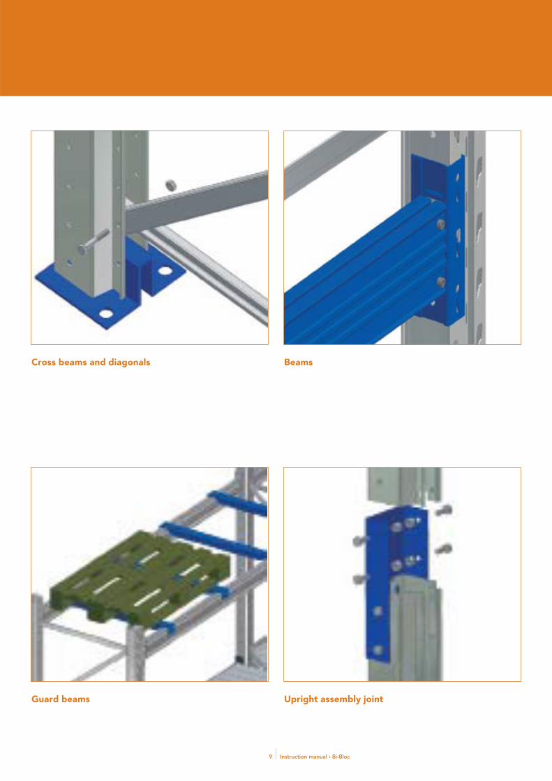
Cross beams and diagonals
Guard beams
Beams
Upright assembly joint

Instruction manual • Bi-Bloc10
INSTALLATION PHASES
Axis drawWhen starting assembly axis must be drawn, by actually drawing on
the fl oor some boxes representing the required lay out of one-sided and
double-sided racks.
Upright frames assembly1) Install the base plate by means of the upright screw hole.
2) Install diagonals, and place the gasket on the fi rst hole (where dia-
gonals do not overlap).
3) Insert locking screws in every hole on uprights and diagonals.
4) Go ahead and install all diagonals that are needed in order to com-
plete an upright frame.
Installation
5) Fit the gasket on the top whole in the last upper diagonal.
6) Tighten all screws by means of an electric screw-
driver aft er having fi tted a locking screw nut on each.
Minimum tightening torque 20 Nm.
7) Upright frame assembly is completed.
8) Install every upright frame in the project, by following the procedu-
res explained insofar.
1 3
42

Instruction manual • Bi-Bloc11
5
6 7
8

Instruction manual • Bi-Bloc12
Upright frames positioning9) Move the fi rst pair of upright frames in the erection area and bring
the fi rst in vertical position. Th is operation requires a minimum of th-
ree persons.
10) Fit a beam in the beam slots and insert a beam stoppers.
11) Repeat the operation with the second upright frame and fi t a beam
as already done on the fi rst. Fix beam stoppers.
12-12a) Insert all other beams as per the project and fi x beam stoppers.
13) M 10x25 screw bolts, to be inserted in upright frames, can be used
to replace beam stoppers.
14) Tighten all screws.
Place all remaining upright frames sequentially, using pallet-bearing
beams as connections.
As soon as double-sided upright frames are installed, proceed with con-
nections. Wherever the original project requires so, make the overall
structure stiff er by use of vertical bracing.
11
9
10
11
12
12 a

Instruction manual • Bi-Bloc13
15) Verify verticality and horizontality by following the table.
16) Accessories include fi ller shoes that can be used only in case of as-
sembled upright frames that do not conform with the specifi ed verti-
cality.
17) Lock tiles with the expanders we supply along with the rack.
Check that all screws and bolts are adequately tightened. Refer to the
tightening torque tables included in this manual and prepare all load
panels that must be attached at the rack’s end.
VERTICALITY: v<H/1000
v = Longitudinal and side out-of perpendicularity
H = Structure height
ALIGNMENT: a = ± 5 mm
a = Maximum structure drift lengthwise and sidewise.
HORIZONTALITY: o = ± 5 mm
o = Maximum drift of fl at parts, when compared with
the original blueprint.
Remarks:
Equipment tolerances are given case by case.
13
14
15
16
17

Instruction manual • Bi-Bloc14
Tile positioning18) A suffi cient quantity of tiles must be carried to the assembly area, a
loading platform will be prepared by using diff erent sized tiles and by
placing them on the tile holders.
19) Lay all tiles until you obtain an even and full platform.
Safety beams positioning20) Insert safety beams. Th e required number of beams depends on the
span.
21) Proceed to install all of them.
18 20
2119
Instruction manual • Bi-Bloc15
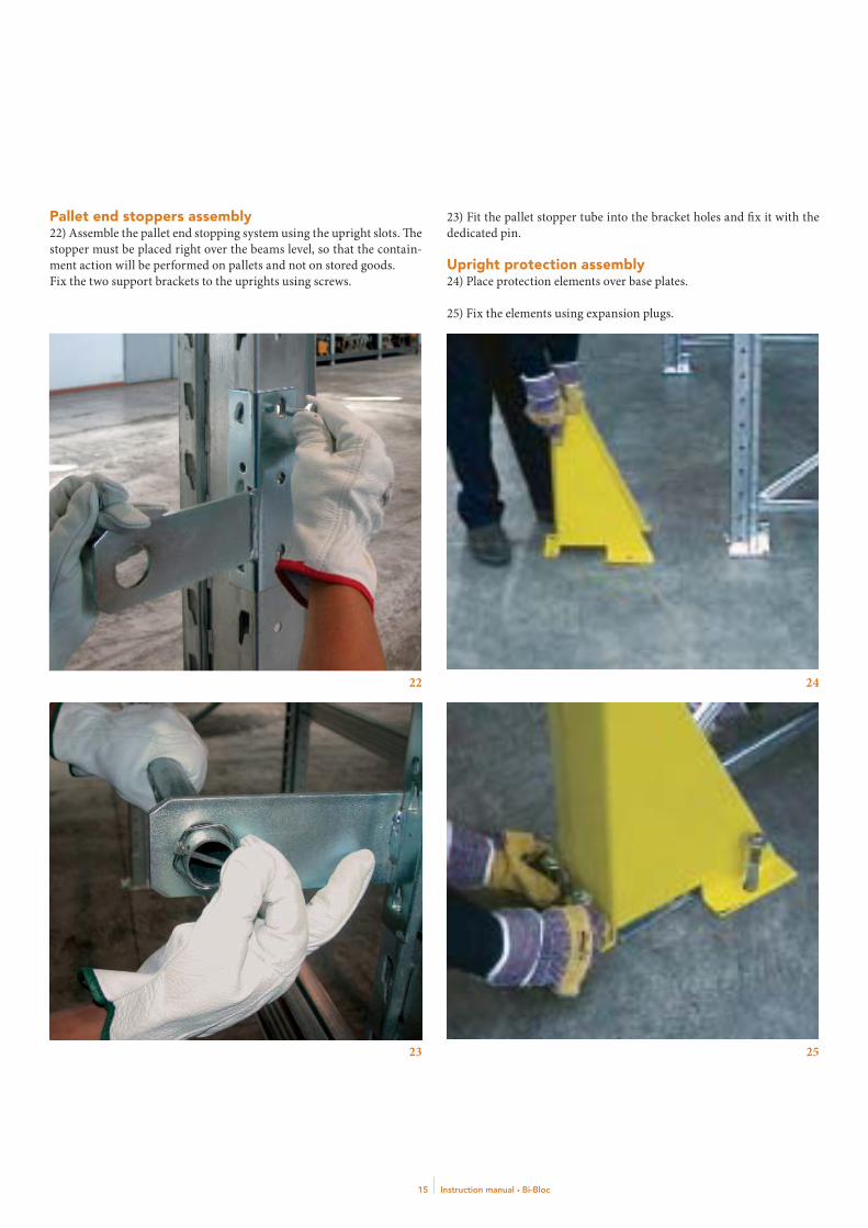
Pallet end stoppers assembly22) Assemble the pallet end stopping system using the upright slots. Th e
stopper must be placed right over the beams level, so that the contain-
ment action will be performed on pallets and not on stored goods.
Fix the two support brackets to the uprights using screws.
23) Fit the pallet stopper tube into the bracket holes and fi x it with the
dedicated pin.
Upright protection assembly24) Place protection elements over base plates.
25) Fix the elements using expansion plugs.
22 24
2523

Instruction manual • Bi-Bloc16
TIGHTENING TORQUE TABLES
• In case of mechanic expanders being used, strictly refer to the manu-
facturer’s data.
• Hexagonal head screws as per UNI 5737 or similar, round head screws
with die-cast hexagon as per UNI 5931.
• Below-head and upon-thread friction factors u=0.14 (Phosphated
black screw, use lubricant before assembly).
• Torque to be applied with dynamometric wrenches. Dead-end
screwdrivers are not considered.
• If such equipment is used, M torque must be reduced by 10%.
• In case cadmium screws are used, reduce M torque by 20%.
• In case large hexagonal head screws are used, increase M torque by 5%.
TIGHTENING TORQUE (Nm) ISO LONG SPAN METRIC THREAD SCREWS
Strength class
Diam. 4.6 4.8 5.6 5.8 6.6 6.8 8.8 10.9 12.9
M3 0.6 0.8 0.7 0.9 0.8 1.1 1.5 2.1 2.5
M4 1.2 1.6 1.5 1.9 1.7 2.3 3.1 4.4 5.2
M5 2.3 3.0 2.8 3.8 3.4 4.5 6.0 8.4 10.1
M6 3.9 5.2 4.9 6.5 5.8 7.8 10.4 14.6 17.6
M8 9.2 12.3 11.5 15.4 13.8 18.5 24.6 34.6 41.5
M10 18.8 25.1 23.5 31.3 28.2 37.6 50.1 70.4 84.6
M12 31.8 42.4 39.8 53.0 47.7 63.6 84.8 119.2 143.1
M14 50.6 67.5 63.3 84.4 75.9 101.3 135.0 189.8 227.9
M16 76.9 102.5 96.1 128.1 115.2 153.8 205.0 288.2 346.0
M18 106.1 141.5 132.7 176.9 159.0 212.3 283.0 397.9 477.7
M20 150.0 200.0 187.6 250.0 224.8 300.0 400.0 562.4 675.2
TIGHTENING TORQUE AS PRESCRIBED BY CNR UNI 10011/88 (plan a-IV)
d (mm) Area(mm2)
Ts (N x m)
4.6 5.6 6.6 8.8 10.9
12 84 39 48 58 90 113
14 115 62 77 93 144 180
16 157 96 121 145 225 281
18 192 133 166 199 309 387
20 245 188 235 282 439 549

Instruction manual • Bi-Bloc17
Constant, systematic checks are required to ensure that the structures remain in good condition over time.
Scheduled maintenance table
DESCRIPTION OF OPERATION
FREQUENCY PROCEDURE
Beam stopper check Every 6 months Check that beam stoppers are effectively in place and that beams are properly inserted in their slots. In case an illegal positioning of beams is found, the loading section must be carefully offl oaded and the beam will be fi xed back in place.
Inspection for collision damage
From 6 months to one year
Check regularly for permanent dents of varying extent caused by collisions.On systems with a high turnover rate, a thorough visual inspection should be performed every 6 months.For other systems, the inspection can be performed annually.The damaged parts must be replaced with genuine components.
Check that structure is vertical
Every 2 years Checks that the structures are vertical must be performed by inspecting the structures of both ends of the system in both directions (lengthways and crossways). Consider the assembly tolerances stated in the manual. Restore structures to the vertical position using shims.
Tools required: Plumbline.
Inspectionof anchoring to the foundations
Every 2 years Check the tightening torque of the expansion plugs.
Tools required: torque wrench calibrated at an authorised laboratory.
Tightness of bolts Every 3 years Check 10% of bays, evenly distributed over the various zones of the drive-in system.In the event that more than 5% of the bolts checked are not properly tightened, proceed to check 50% of bays.In the event that more than 10% of the bolts checked are not properly tightened, proceed to check 100% of bays.At the next inspection, check the bays not checked the time before.
Tools required: torque wrench calibrated at an authorised laboratory.
Inspectionof galvanisedand painted fi nishes
From one to 5 years
Check the condition of the galvanised or painted fi nishes at a frequency decided depending on the installation location: in corrosive environments, inspect every year; in normal indoor environments, the inspection interval may be as long as 5 years.
Instructionsfor proper maintenance

Instruction manual • Bi-Bloc18
Th e method adopted for the identifi cation of risks is based on the
identifi cation of processes involved in the construction of the sys-
tem.
Th e risks were identifi ed for each process, and then evaluated on the
basis of the legal requirements and the rules of good practice, the en-
vironmental context, and the simultaneous and/or consecutive pres-
ence of diff erent contractors and/or diff erent processes.
Semi-qualitative scalesRisks were assessed with the aid of the two semi-qualitative scales:
• D index scale: indicates the potential damage related to the risk
• P index scale: indicates the probability and frequency with which
an event may occur
For allocation of the values 0,1, 2 and 3, the occurrence of even just one
of the conditions stated in the “criteria” column is suffi cient. Naturally,
the allocation of one of the values does not imply a prediction that all
the conditions corresponding to the value chosen, listed in the “criteria”
column, will apply.
Assignment of risk categoriesTo assign a risk category, the two indicators, D and P, must be corre-
lated by placing them on Cartesian axes and taking the value assig-
ned on a sectorial basis as reference:
Risk categories are assigned as follows:
A-SLIGHT: Risk conditions for which the monitoring of the potential ha-
zards has to be maintained or implemented.
B-MINOR: Risk conditions for which monitoring of the potential ha-
zards has to be established to identify any increase.
C-MODERATE, D-HIGH: Risk conditions for which preventive and pro-
tective measures have to be adopted to reduce the risks in relation to the
degree of risk identifi ed.
D INDEX (POTENTIAL DAMAGE) SCALE
VALUE CRITERIA
3
Damage causing irreversible injuries(death, anatomical and/or functional loss).Injuries producing temporary disability with initial prognosisof recovery in > 40 days may occur.There is a correlation between the procedureand the possibility of death or permanent disability.
2
Injuries producing temporary disability with initialprognosis of recovery in > 21 days may occur.There is a correlation between an accident during a stageof the process and the risk of injury with partial or total stoppage of operations lasting > 30 days and/or the production of limited environmental contamination.
1
Injuries producing temporary disability with initial prognosisof recovery in ≤ 21 days may occur.There is a correlation between an accident during a stageof the process and the risk of injury with partial or total stoppage of operations lasting > 1 and ≤ 30 days.
0
Injuries producing temporary disability with initial prognosisof recovery in ≤ 3 days may occur.There is a correlation between an accident during a stageof the process and the risk of injury with partial or total stoppage of operations lasting ≤ 1 day.
P INDEX (PROBABILITY - FREQUENCY OF EVENTS) SCALE
VALUE CRITERIA
3
There is a direct correlation between the risk factor and the cause related to a form of damage.Damage has already occurred due to the problem identifi ed (accidents, injuries, occupational illnesses).There is a correlation between the procedure and/or the risk factor and the deterioration of the accident rate and/or the rate of occupational illness over a signifi cant period (three to fi ve years). The likelihood of an accident is ≥ 2*10-2
2
The risk factor may cause damage, although not automatically or directly.Occasions on which the problem noted has led to the damage are recorded.There is a correlation between the procedure and/or the risk factor and a random trend in the accident rate and/or the rate of occupational illness over a signifi cant period (three to fi ve years). The likelihood of an accident is < 2*10-2 e ≥ 3*10-3
1
The factor may only cause damage in occasional circumstances or due to an unlucky combination of events.No occurrences are known, or they have been rare.There is a correlation between the procedure and a positive trend in the accident rate and/or the rate of occupational illness over a signifi cant period (three to fi ve years).The likelihood of an accident is < 3*10-3 e ≥ 3*10-5
D IN
DE
X
(PO
TEN
TIA
L D
AM
AG
E) 3 C D D
2 B C D1 A B C0 A A B
1 2 3
P INDEX (PROBABILITY OR FREQUENCY OF EVENTS)
Risk identifi cation, analysis and assessment

Instruction manual • Bi-Bloc19
MARKING OF UPRIGHT FRAME OUTLINES ON THE FLOOR
OperationMarking of the outlines of the upright frames on the fl oor (laying of
“marker lines”).
Work placePlace where the shelving system is installed.
x Type of riskPossible interference, to be assessed on a case-by-case basis, with ac-
tivities carried out at the same time (e.g. installation of electrical or air-
conditioning systems, masonry fi nishing operations).
Preparations and equipment required to guarantee compliance with the regulationsTh e requirements to be met for compliance with the regulations must
be assessed on a case-by-case basis depending on the characteristics of
the place of installation.
Performance proceduresTo be decided on a case-by-case basis depending on the characteristics
of the place of installation.
TRANSPORTATION OF BI-BLOC COMPONENTS TO THE WORK SITE
OperationUnloading of shelving system components from the truck.
Work placeAs specifi ed in plan.
x Type of riskSmall metal parts (metal fasteners, etc.) striking workers.
Preparations and equipment required to guarantee compliance with the regulationsSuch loads must only be lift ed using metal buckets or bins;
the use of open platforms or slings is not permitted (art. 58 of Italian
Presidential Decree 164/56).
Performance proceduresInforming of workers with regard to the procedures to be adopted when
lift ing (raising and lowering) loads.
If the material for unloading is not in small pieces, bundles of sections
or other materials may be lift ed with two slings of the same length with
the aiding of lift ing machinery (e.g. a truck-mounted crane).
Damage index: 2
Probability index: 2
Risk index: C
x Type of riskBruises to the head.
Preparations and equipment required to guarantee compliance with the regulationsUse of hard helmet.
Damage index: 2
Probability index: 2
Risk index: C
x Type of riskBruises to the feet.
Preparations and equipment required to guarantee compliance with the regulationsUse of puncture resistant safety footwear.
Damage index: 2
Probability index: 1
Risk index: B
x Type of riskCuts or grazes to the hands.
Preparations and equipment required to guarantee compliance with the regulationsUse of protective gloves.
Damage index: 1
Probability index: 2
Risk index: B
x Type of riskBack injury.
Preparations and equipment required to guarantee compliance with the regulationsAssess loads during this stage. In general, if the average weight lift ed by
a person is more than 25 kg, there is a risk of back injury.
Depending on the company, this general statement must be backed up
by a risk assessment (pursuant to Italian Decree Law 81/2008) bearing
in mind all parameters (actual weight of the load, handling conditions,
frequency, etc.) required to provide a complete risk assessment.
If risks of this kind are actually identifi ed, the employer (contractor
performing the installation) must fulfi l all the obligations required by
Decree Law n. 81/2008, (health monitoring, information and training
of workers).

Instruction manual • Bi-Bloc20
Damage index: 2
Probability index: 2
Risk index: C
STORAGE OF BI-BLOCCOMPONENTS
OperationCreation of a storage area for the materials.
Work placeTo be specifi ed in the plan.
x Type of riskMaterial falling onto people.
Preparations and equipment required to guarantee compliance with the regulationsTh e materials must be placed or stacked in such a way as to prevent col-
lapse or overturning (Decree Law 81/2008). Use helmets and puncture
resistant safety footwear.
Performance proceduresProvide the workers concerned with instructions on the way in which
the materials are to be stacked and where to stack them.
Damage index: 2
Probability index: 2
Risk index: C
x Type of riskFire caused by fl ammable materials (paints, solvents, etc.).
Preparations and equipment required to guarantee compliance with the regulationsEven small amounts of fl ammable materials (paints, solvents) must be
stored away from sources of heat, equipment which causes sparks, and
electrostatic discharges, and must be in sealed containers.
No smoking signs must be provided in the places where these materials
are stored.
A class 13A - 89BC powder fi re extinguisher must be provided in the
store containing this material. If more than small amounts of fl amma-
ble materials are present, the number of extinguishers must be increa-
sed, and units with extinguishing capacity of at least 21A 89BC must
be installed.
If, for example, the quantity of paint exceeds 500 kg, fi re prevention
certifi cation must be applied for (point 20 of Ministerial Decree of
16/2/1982). Th e access door to the store must have a raised threshold to
prevent leaks.
A ventilation opening should be provided (as a guideline, at least 1/100
of the fl oor area of the room).
Damage index: 2
Probability index: 1
Risk index: B
x Type of riskCuts or grazes to the hands.
Preparations and equipment required to guarantee compliance with the regulationsUse of protective gloves.
Damage index: 1
Probability index: 2
Risk index: B
ASSEMBLING THE UPRIGHT FRAMES
OperationAssembly of the various elements which make up the upright frames
using bolts, and transfer of the assembled upright frame from the work-
surface (trestles) to the storage position (which may be temporary depo-
sit in the installation site).
Work placeAs specifi ed in plan.
x Type of riskNoise exposure
Preparations and equipment required to guarantee compliance with the regulationsNoise assessment (Decree Law 277/91).
Performance proceduresTh e use of ear plugs or ear defenders is recommended when using an
electric screwdriver (as a precautionary measure).
Damage index: 2
Probability index: 1
Risk index: B
x Type of riskCuts or grazes to the hands.
Preparations and equipment required to guarantee compliance with the regulations

Instruction manual • Bi-Bloc21
Use of protective gloves.
Performance proceduresDraw up a procedure for the manual handling of the upright frames
on the basis of the results of the health monitoring operations and the
characteristics of the loads (NIOSH regulations).
Damage index: 2
Probability index: 1
Risk index: B
x Type of riskBruises to the feet.
Preparations and equipment required to guarantee compliance with the regulationsUse of puncture resistant safety footwear.
Damage index: 2
Probability index: 1
Risk index: B
x Type of riskBack injury due to the manual handling of loads.
Preparations and equipment required to guarantee compliance with the regulations Assess loads during this stage. In general, if the average weight lift ed by
a person is more than 25 kg, there is a risk of back injury.
Depending on the company, this general statement must be backed up
by a risk assessment bearing in mind all parameters (actual weight of
the load, handling conditions, frequency, etc.) required to provide a
complete risk assessment.
If risks of this kind are actually identifi ed, the employer (contractor
performing the installation) must fulfi l all the obligations required by
Decree Law n. 81/2008, (health monitoring, information and training
of workers).
Damage index: 2
Probability index: 2
Risk index: C
x Type of riskInjury due to the exposure of the upper limbs to vibration during the
use of electric or pneumatic screwdrivers.
Preparations and equipment required to guarantee compliance with the regulations In generale la somma vettoriale delle accelerazioni rilevate sui tre assi
in condizioni normali di impiego supera i 5 m/s2. Tale valore è accettato
dalla letteratura scientifi ca come “soglia di intervento” al di sopra della
quale occorre prevedere misure di prevenzione e protezione. In questo
caso è da prescriversi l’uso di guanti antivibrazione e la sorveglianza
sanitaria.
Damage index: 2
Probability index: 2
Risk index: C
x Type of riskKnocks to the head.
Preparations and equipment required to guarantee compliance with the regulationsUse of protective helmet.
Damage index: 2
Probability index: 2
Risk index: C
x Type of riskElectrocution due to the use of electric screwdrivers.
Preparations and equipment required to guarantee compliance with the regulations Portable devices (electric screwdrivers) must have double insulation
(class II) identifi ed by the symbol of two concentric squares. Power
supply sockets must be fi tted with a device which prevents accidental
removal of the plug. Unsecured plug sockets may be used provided they
comply with the CEI 23-12 “Industrial plug sockets” standard.
Unsecured plug sockets and their power supply cables must be protec-
ted against mechanical damage.
Cables laid temporarily must be fl exible (H07 RN -–F) with rubber in-
sulation with polychloroprene (PCP) or equivalent sheathing. Whether
unsecured or permanently mounted, plug sockets must have at least
IP44 protection. In particularly hazardous work site environments
(presence of water, etc.) use of a higher degree of protection (IP55 or
IP67) should be considered.
Portable devices must be connected to an electricity supply system fi t-
ted with a high-sensitivity diff erential safety breaker having tripping
threshold Id of 30 mA or below; a single diff erential safety breaker may
protect up to 6 sockets on the same panel.
For overload protection, a magnetothermic switch must be installed
for each socket, unless the power supply to the panel is protected by
a single magnetothermic switch having rated current the same as the
lowest of the rated currents of the plug sockets.
Th e power supply panel must have protection appropriate to the envi-
ronment where it is used (at least IP43).
Damage index: 3

Instruction manual • Bi-Bloc22
Probability index: 1
Risk index: C
TRANSPORTATION OF UPRIGHT FRAMES AND SHELVING TO THE INSTALLATION SITE
OperationTransfer of assembled upright frames, beams and bolts by fork-lift truck
from store to installation position.
Work placeRoute from store to installation site.
x Type of riskHitting of workers with parts of the upright frames which project from
the fork-lift truck during transport.
Preparations and equipment required to guarantee compliance with the regulationsProvide traffi c lanes of suitable width for the dimensions of the load and
the characteristics of the work site.
Safety helmets must be worn both by the fork-lift truck driver and the
workers on the work site.
Damage index: 2
Probability index: 1
Risk index: B
x Type of riskHitting of workers with parts of the upright frames which project from
the fork-lift truck during transport.
Preparations and equipment required to guarantee compliance with the regulationsPlace the load on the fork-lift truck in accordance with the instructions
provided by the truck’s manufacturer, to ensure that it does not fall off
in transit. Improve the driver’s front view by placing the transported
load, in accordance with the instructions provided by the manufacturer
of the fork-lift truck, in such a way that it does not obstruct the lines of
vision needed for safe driving (note that an incorrectly positioned load
distracts the driver’s attention, meaning that he pays less attention to
any people present in the vicinity). Anyone assigned to follow the tran-
sported load from close at hand should wear a high-visibility vest.
Damage index: 2
Probability index: 1
Risk index: B
x Type of riskOverturning of the fork-lift truck.
Preparations and equipment required to guarantee compliance with the regulationsEnsure that the fork-lift truck driver receives suitable training;
Th e driving position must have appropriate protection against crushing
in the event that the truck overturns (in general, this protection is pro-
vided by fi tting the truck with an enclosed cab).
When reversing, fork-lift truck drivers must be assisted by a person
on the ground.Passengers must not be carried unless permitted by the
truck’s manufacturer in the driver’s cab.
Damage index: 3
Probability index: 1
Risk index: C
x Type of riskImproper use of the fork-lift truck.
Preparations and equipment required to guarantee compliance with the regulations No workers who have not received the information, training and in-
struction required by the relevant regulations must be allowed to use
fork-lift trucks.
Damage index: 1
Probability index: 2
Risk index: B
x Type of riskAccidental operation of load handling controls.
Preparations and equipment required to guarantee compliance with the regulationsFor fork-lift trucks placed on the market, and/or put into service before
Presidential Decree no. 459/96 came into force, and which do not have
the CE marking pursuant to the “Machinery Directive”.
• All load control devices must have automatic return to the idle position;
• Load control devices must be of the “hold-to-run” type and operated
by electrical, mechanical or other systems;
• Load control devices must be placed and arranged in such a way that
they cannot be accidentally operated, especially with regard to the spe-
cifi ed route for access to the vehicle’s driving and control position (see
Ministry of Labour and Social Security Circular no. 50/98).
For fork-lift trucks with CE marking, the measures specifi ed above do
not apply, since this marking confi rms that the manufacturer has com-
plied with the essential safety requirements for the machine (Presiden-
tial Decree no. 459/1996).
Damage index: 2
Probability index: 2
Risk index: C

Instruction manual • Bi-Bloc23
x Type of riskShearing or crushing of parts of the operator’s body by parts of the fork-
lift truck moving in relation to each other.
Preparations and equipment required to guarantee compliance with the regulationsChains, sprockets or other moving parts in any way accessible to the
drivers or others must be fully protected by means of guards.
As an alternative to these guards, “safety distances” between moving
parts are equally acceptable (see Ministry of Labour and Social Security
Circular no. 50/98).
Damage index: 2
Probability index: 2
Risk index: C
x Type of riskNoise exposure.
Preparations and equipment required to guarantee compliance with the regulationsTh e use of ear plugs or ear defenders is recommended (as a precautio-
nary measure).
Damage index: 2
Probability index: 1
Risk index: B
UPRIGHT FRAME ASSEMBLY WITH THE LOWER LEVEL OF BEAMS
OperationLift ing upright frames and locking them with the fi rst beam row.
Work placeAs per layout.
x Type of riskHands cuts or bruises.
Preparations and equipment required to guarantee compliance with the regulationsUse protection glove.
Damage index: 2
Probability index: 1
Risk index: B
x Type of riskFoot bruises.
Preparations and equipment required to guarantee compliance with the regulationsUse steel sole toe shoes.
Damage index: 2
Probability index: 1
Risk index: B
x Type of riskBack and lumbar damages because of manual manipulation of loads.
Preparations and equipment required to guarantee compliance with the regulationsAssess loads during this stage. In general, given the average weight of
the upright frames (90 - 150 kg) it can be stated that there is a risk of
back injury. In this case the employer (contractor performing the in-
stallation) must fulfi l all the obligations required by Decree Law no.
81/2008, (health monitoring, information and training of workers).
Damage index: 2
Probability index: 2
Risk index: C
x Type of riskRisk of being hit by falling or dropped materials.
Preparations and equipment required to guarantee compliance with the regulationsUse hard hats.
Damage index: 3
Probability index: 1
Risk index: C
x Type of riskRisk of being hit by collapsing unbalanced uprights due to mishandling.
Performance proceduresDraw up a appropriate assembly procedure, complete with any hand
signals for communications (see Decree Law 493/96).
Damage index: 3
Probability index: 1
Risk index: C

Instruction manual • Bi-Bloc24
x Type of riskHitting of workers with parts of the upright frames which project from
Damages cause by upper limbs exposures to vibrations cause by an elec-
tric or air-powered screw-driver
Preparations and equipment required to guarantee compliance with the regulationsIn general, the vector sum of the accelerations measured on the three axes
in normal conditions of use exceeds 5 m/s2. In the scientifi c literature,
this value is accepted as the “trigger threshold” above which preventive
and protective measures must be taken. In this case, the use of vibration-
damping gloves and health monitoring must be enforced.
Damage index: 2
Probability index: 2
Risk index: C
x Type of riskElectrocution caused by an electric screwdriver.
Preparations and equipment required to guarantee compliance with the regulationsSee operation n.4, paragraph 7.
ASSEMBLING BEAMS AND ACCESSORIES AT HIGHER LEVELS
OperationAssembly of the shelving and accessories at a height exceeding 2 m.
Work placeAs envisaged by the design.
x Type of riskCuts or grazes to the hands.
Preparations and equipment required to guarantee compliance with the regulationsUse of protective gloves.
Damage index: 2
Probability index: 1
Risk index: B
x Type of riskBruises to the feet.
Preparations and equipment required to guarantee compliance with the regulationsUse of puncture resistant safety footwear.
Damage index: 2
Probability index: 1
Risk index: B
x Type of riskBack injury due to the manual handling of loads.
Preparations and equipment required to guarantee compliance with the regulationsAssess loads during this stage. In general, since the average weight of
the elements handled is 20 kg (to be subdivided by the two workers
who assemble the parts), the risk of back injury can be considered to
be under control and therefore acceptable.
If a risk of this kind is actually identifi ed, the employer (contractor
performing the installation) must fulfi l all the obligations required by
Decree Law no. 81/2008, (health monitoring, information and trai-
ning of workers).
Damage index: 2
Probability index: 1
Risk index: B
x Type of riskInjuries due to falling objects.
Preparations and equipment required to guarantee compliance with the regulationsUse of safety helmet for both the assigned workers and for other workers
present during the operation (also those from other companies).
Damage index: 3
Probability index: 1
Risk index: C
x Type of riskFall from height.
Preparations and equipment required to guarantee compliance with the regulationsUse of motorised and other equipment allowing work to be carried out
using platforms fi tted with parapets. Working cages lift ed by lift ing
equipment may also be used within the limits set by art. 184 of Pre-
sidential Decree no. 547/55 and further to the installation of eff ective
cage (or basket) safety devices as envisaged by Ministry of Labour and
Social Security Circular no. 103/98.
A properly anchored safety harness can be used only where the use
of equipment of this kind is not possible (e.g. during installation with
aisles less than 1.70 – 1.50 metres wide).
Damage index: 3
Instruction manual • Bi-Bloc25
Probability index: 2
Risk index: D
x Type of riskInjury due to the exposure of the upper limbs to vibration during the
use of electric or pneumatic screwdrivers.
Preparations and equipment required to guarantee compliance with the regulationsIn general, the vector sum of the accelerations measured on the three
axes in normal conditions of use exceeds 5 m/s2.
In the scientifi c literature, this value is accepted as the “trigger thre-
shold” above which preventive and protective measures must be taken.
In this case, the use of vibration-damping gloves and health monitoring
must be enforced.
Damage index: 2
Probability index: 2
Risk index: C
x Type of riskElectrocution due to the use of electric screwdrivers.
Preparations and equipment required to guarantee compliance with the regulationsSee operation n. 4, paragraph 7.
PAINTING OF SMALL AREAS OF METAL COMPONENTS
OperationPainting with paints or enamels.
Work placeShelving system.
x Type of riskInhalation of harmful chemicals (solvents).
Preparations and equipment required to guarantee compliance with the regulationsFollow the instructions provided in the product safety information; in
all cases, a facial half-mask with A2 fi lter is recommended.
Damage index: 2
Probability index: 2
Risk index: C
x Type of riskContact between skin and harmful chemicals (solvents, paints).
Preparations and equipment required to guarantee compliance with the regulationsFollow the instructions provided in the product safety information;
in all cases, chemical-resistant gloves should be worn.
Damage index: 2
Probability index: 2
Risk index: C
x Type of riskKnocks to the head from collisions with shelving system elements.
Preparations and equipment required to guarantee compliance with the regulationsUse of protective helmet.
Damage index: 2
Probability index: 1
Risk index: B
x Type of riskFoot crushing or puncturing.
Preparations and equipment required to guarantee compliance with the regulationsUse of puncture resistant safety footwear.
Damage index: 2
Probability index: 1
Risk index: B
x Type of riskFire or explosion.
Preparations and equipment required to guarantee compliance with the regulationsDo not carry out painting jobs while open fl ames are used, or sparks or
electrostatic charges are generated, in the vicinity.
Do not leave paint containers open.
Damage index: 2
Probability index: 1
Risk index: B

Instruction manual • Bi-Bloc26
ASSEMBLING GROUND LEVEL COMPONENTS
OperationAnchoring of metal elements to the fl oor.
Work placePlace where the shelving system is installed.
x Type of riskInhalation of dust generated by use of drills.
Preparations and equipment required to guarantee compliance with the regulationsUse of protective masks.
Damage index: 2
Probability index: 1
Risk index: B
x Type of riskExposure to the noise produced by drills.
Preparations and equipment required to guarantee compliance with the regulationsEarplugs or noise-proof headset as recommended (pre-emptive measures).
Damage index: 2
Probability index: 1
Risk index: B
x Type of riskKnocks to the head from collisions with shelving system elements.
Preparations and equipment required to guarantee compliance with the regulationsUse of protective helmet.
Damage index: 2
Probability index: 1
Risk index: B
x Type of riskFoot crushing or puncturing.
Preparations and equipment required to guarantee compliance with the regulationsUse of puncture resistant safety footwear.
Damage index: 2
Probability index: 1
Risk index: B
x Type of riskElectrocution due to the use of electric screwdrivers.
Preparations and equipment required to guarantee compliance with the regulationsSee operation n.4, paragraph 7.
VERTICALITY CHECKS AND INSPECTIONS FOR CORRECT INSTALLATION
OperationInspection of Bi-Bloc sections, including high locations.
Work placeRack.
x Type of riskPrecipitation.
Preparations and equipment required to guarantee compliance with the regulationsUse of motorised and other equipment allowing work to be carried out
using platforms fi tted with parapets.
Working cages lift ed by lift ing equipment may also be used within the
limits set by art. 184 of Presidential Decree no. 547/55 and further to
the installation of eff ective cage (or basket) safety devices as envisaged
by Ministry of Labour and Social Security Circular no. 103/98.
A properly anchored safety harness can be used only where the use
of equipment of this kind is not possible (e.g. during installation with
aisles less than 1.70 – 1.50 metres wide).
Damage index: 3
Probability index: 2
Risk index: D
x Type of riskHead bumps against rack elements.
Preparations and equipment required to guarantee compliance with the regulationsUse hard hats.
Damage index: 2
Probability index: 2

Instruction manual • Bi-Bloc27
Risk index: C
x Type of riskFoot crushing or puncturing.
Preparations and equipment required to guarantee compliance with the regulationsUse of puncture resistant safety footwear.
Damage index: 2
Probability index: 1
Risk index: B
TESTING OF BI-BLOC
OperationInspection of Bi-Bloc sections, including high locations.
Possible loading test.
Work placeRack.
x Tipologia di rischioPrecipitation.
Preparations and equipment required to guarantee compliance with the regulationsUse of motorised and other equipment allowing work to be carried out
using platforms fi tted with parapets. Working cages lift ed by lift ing
equipment may also be used within the limits set by art. 184 of Pre-
sidential Decree no. 547/55 and further to the installation of eff ective
cage (or basket) safety devices as envisaged by Ministry of Labour and
Social Security Circular no. 103/98.
A properly anchored safety harness can be used only where the use
of equipment of this kind is not possible (e.g. during installation with
aisles less than 1.70 – 1.50 metres wide).
Damage index: 3
Probability index: 2
Indice di rischio: D
x Type of riskRisk of being hit by materials placed on racks during load tests.
Preparations and equipment required to guarantee compliance with the regulationsUse of protective helmets; fencing of the entire area involved with movable
barriers and placing of a suitable number of warning signs stating “No pe-
destrian access” or “No unauthorised access”, as appropriate.
Damage index: 2
Probability index: 2
Risk index: C
x Type of riskFoot crushing or puncturing.
Preparations and equipment required to guarantee compliance with the regulationsFoot crushing or puncturing.
Damage index: 2
Probability index: 1
Risk index: B

Instruction manual • Bi-Bloc28
Notes

via Giovanni della Casa, 1220151 Milano - Italytel. +39 . 02 30 704 1 fax +39 . 02 33 402 [email protected]
storage system divisiondivisione magazzinaggio
• se
ttem
bre
20
09
- In
gles
e
Codice manuale: 00000000SQMANING07 edizione September 2009 - rev.0