Embed Size (px)
Citation preview

PALO VERDE NUCLEAR GENERATING STATION
Mechanical Maintenance Training
Classroom Lesson
Mechanical Maintenance Training Date: 5/7/2009
LP Number: NMS01C000301 Rev Author: CURT CLUFF
Title: Snubber Identification and Inspection Technical Review:
Duration : 4 HOURS Teaching Approval:

Mechanical Maintenance Training Page: 2 of 38
Title: Snubber Identification and Inspection Lesson Plan #: NMS01C000301
INITIATING DOCUMENTS Task Analysis of Tasks
REQUIRED TOPICS None
CONTENT REFERENCES VTM-I207-00002, ITT Grinnell Mechanical Shock, Sway Suppressors and Associated Equipment
VTM -P-970-00001: Paul Monroe S/G & RCP Snubbers [P209-B, P209-B2, 50-3, 51-1, 52-1]
PVNGS Technical Specification 3/4.7.9, ITS T 3.7.101
Station Manuals Procedures 73ST-9ZZ10, 73ST-9ZZ21, 73ST-9ZZ22, 73ST-9ZZ23, 31MT-9ZZ15, 73DP-9ZZ16
VTM-P029-00001, PSA snubber Tech. Manuals [PSA-192, 193, 194, 141.]
VTM-P-970-00002, Installation-Operation-Maintenance for C-E System 80 Pump Shock Struts
VTM-P-970-00004, Installation-Operation-Maintenance for D-E System 80 Steam Generator Snubber
CRDR 2380811, 2561284, & 2645470; personnel injuries while working on snubbers
CRDR 118407 & 2357504, Improper documentation/control for snubber replacement parts
LESSON PLAN REVISION DATA
May 07, 2009 Curt Cluff Added hands-on exercise for inspection to enhance learning (TCSAI 3324454)
Mechanical Maintenance Training Page: 3 of 38
Title: Snubber Identification and Inspection Lesson Plan #: NMS01C000301
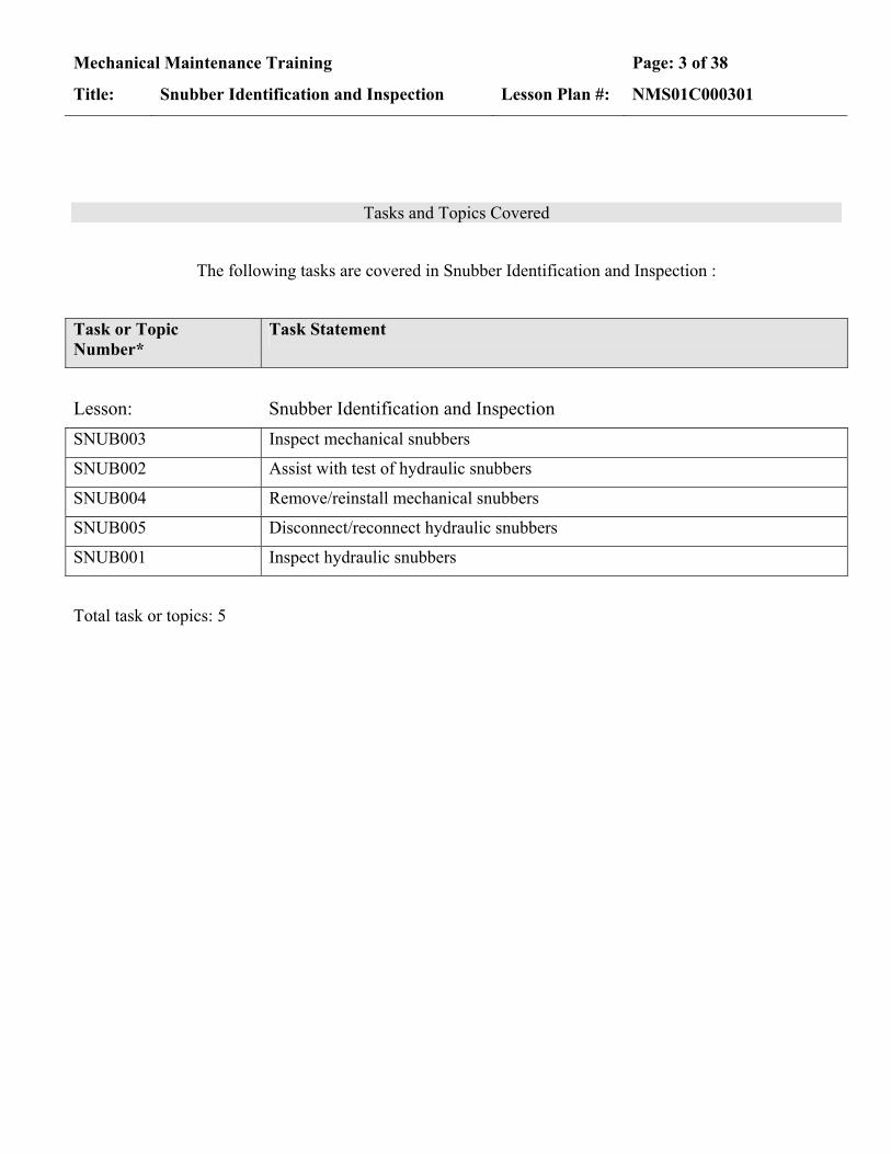
Tasks and Topics Covered
The following tasks are covered in Snubber Identification and Inspection :
Task or Topic Number*
Task Statement
Lesson: Snubber Identification and Inspection SNUB003 Inspect mechanical snubbers
SNUB002 Assist with test of hydraulic snubbers
SNUB004 Remove/reinstall mechanical snubbers
SNUB005 Disconnect/reconnect hydraulic snubbers
SNUB001 Inspect hydraulic snubbers
Total task or topics: 5

Mechanical Maintenance Training Page: 4 of 38
Title: Snubber Identification and Inspection Lesson Plan #: NMS01C000301
TERMINAL OBJECTIVE:
1 Given a maintenance situation, the mechanical student will , describe how to identify snubber types and perform normal and post-transient visual inspection of both mechanical and hydraulic snubbers as demonstrated by passing the final exam with a minimum grade of 80%.
1.1 Distinguish between Pacific Scientific (PSA) and ITT Grinnell snubbers
1.2 State the normal inspection criteria and the data recorded for mechanical snubbers
1.3 State the inspection criteria for post transient events and the data recorded for mechanical snubbers
1.4 State the procedure for the removal of mechanical snubbers
1.5 State the procedure for the proper fit-up and adjustment of mechanical snubbers during installation
1.6 State the normal and post-transient inspection criteria and the data recorded for hydraulic snubbers
1.7 State the major steps in the 5 and 10 year surveillance tests of the S/G and RCP hydraulic snubbers
1.8 Perform classroom exercise of a visual inspection of a mechanical snubber

Mechanical Maintenance Training Page: 5 of 38
Title: Snubber Identification and Inspection Lesson Plan #: NMS01C000301
Lesson Introduction: Snubber Identification and Inspection
The following items are things to consider in your Lesson Introduction. They are not mandatory.
CONTENT METHODS & ACTIVITIES
I. Motivation
A. Now look at the actual tasks to be performed on the snubbers
B. Inspection is a regular item that sometimes includes removal and replacement
C. Some maintenance is also required occasionally on the hydraulic snubbers in addition to supporting the vendor testing
D. Qualification is required to perform the tasks identified in this lesson plan
Focus student attention on “What’s In It For Me”.
II. Lesson Introduction Introduce the lesson material
A. Lesson Terminal Objective Given a maintenance situation, the mechanical student will describe how to identify snubber types and perform normal and post-transient visual inspection of both mechanical and hydraulic snubbers as demonstrated by passing the final exam with a minimum grade of 80%.
Read and/or discuss the lesson objectives (Slide)

Mechanical Maintenance Training Page: 6 of 38
Title: Snubber Identification and Inspection Lesson Plan #: NMS01C000301
CONTENT METHODS & ACTIVITIES
B. Lesson Enabling Objectives
EO01 Distinguish between Pacific Scientific (PSA) and ITT Grinnell snubbers.
EO02 State the normal inspection criteria and the data recorded for mechanical snubbers.
EO03 State the inspection criteria for post transient events and the data recorded for mechanical snubbers.
EO04 State the procedure for the removal of mechanical snubbers.
EO05 State the procedure for the proper fit-up and adjustment of mechanical snubbers during installation.
EO06 State the normal and post-transient inspection criteria and the data recorded for hydraulic snubbers.
EO07 State the major steps in the 5 and 10 year surveillance tests of the S/G and RCP hydraulic snubbers.
EO08 Perform classroom exercise of a visual inspection of a mechanical snubber

Mechanical Maintenance Training Page: 7 of 38
Title: Snubber Identification and Inspection Lesson Plan #: NMS01C000301
TO: 1 Given a maintenance situation, the mechanical student will , describe how to identify snubber types and perform normal and post-transient visual inspection of both mechanical and hydraulic snubbers as demonstrated by passing the final exam with a minimum grade of 80%.
EO: 1.1 Distinguish between Pacific Scientific (PSA) and ITT Grinnell snubbers
CONTENT METHODS & ACTIVITIES
I. Identification
A. Why do we care?
1. All snubbers are PSA snubbers
Show differences in attachments so they can identify proper torque values and anti-seize
2. Attachments to the snubbers are either PSA or ITT Grinnell
Prevent Events – self-check w/ procedure to ensure you know which
3. Torque charts are different for the two
B. ITT Grinnell snubbers (Slide)
1. Structure mounting brackets
a. Army green in color
b. Clevis mounts are welded to the base
c. Base extends past the clevis mounts
d. Forward bracket is painted
e. On 35 model, bases are rectangular (Slide)
2. Hardware
a. Extension and transition tubes
(1) Should have metal hanger identification tags attached

Mechanical Maintenance Training Page: 8 of 38
Title: Snubber Identification and Inspection Lesson Plan #: NMS01C000301
CONTENT METHODS & ACTIVITIES
(2) 1/4 to 10 models have adjustable transition tube assemblies
(3) Hanger identification tags mounted on snubber body
(4) Allen head capscrews vice standard hex head capscrews
b. Due to interchangeability of snubbers, tag on snubber body may have the wrong hanger identification
C. PSA snubbers Point out differences between PSA and ITT Grinnell attachments
1. Structure mounting brackets (Slide)
a. Gray in color
b. Clevis mounts are mounted to base
c. Base is same size as mounts
d. 35 model, bases are "H" shaped
e. Forward bracket is same color as housing (Slide)
f. Bolts attaching front brackets to the snubber are lockwired
g. Pipe to snubber bracket
(1) Bolts are gold in color
(2) Ends of pipe brackets are different from ITT Grinnell
2. Hardware
a. Load pins and load studs are stainless steel This explains why different anti-seize compound is different
b. Bolts are electroplated

Mechanical Maintenance Training Page: 9 of 38
Title: Snubber Identification and Inspection Lesson Plan #: NMS01C000301
EO: 1.2 State the normal inspection criteria and the data recorded for mechanical snubbers
CONTENT METHODS & ACTIVITIES
I. Mechanical snubbers (normal inspection)
A. Prerequisites
1. If insulation covers attachments, it will have to be removed
2. Ensure no interferences prevent a complete inspection
B. Name plate data (Slide) name plate data
1. EQID – Hanger tag number Show nameplate on Training Aid
a. Red or yellow bakelite tag
b. May be marked on support or wall with paint marker
Note that plant policy should have you order a tag – marker not acceptable
2. Snubber size
3. Serial number Prevent Events – self-check the number when documenting
C. Required data for operability (Slide) show inspection points on snubber (use training aid also)
1. As Found Cold Position within ½” of expected position indicating freedom of movement
2. No visible damage or corrosion (physical damage, dents, dings, etc.)
3. No damaged or loose parts on attachments
a. Spherical bearing bushings in place
b. Extensions not bent

Mechanical Maintenance Training Page: 10 of 38
Title: Snubber Identification and Inspection Lesson Plan #: NMS01C000301
CONTENT METHODS & ACTIVITIES
4. Fasteners secured and functional
a. Nuts and bolts
b. Spacers and washers
5. Welds should be intact
a. Clevis mounts
b. Attachments
c. Wall brackets
d. Do not remove paint for inspection
6. Swing clearance (Slide)
a. No obstruction
b. Within a 5 degree cone from centerline
D. Comments section
1. Note all relatable data or problems not covered
2. Initial and date Successful completion of this course will qualify the student as a snubber examiner.
3. Provide explanatory sketch if necessary Prevent Events – communication allows accurate evaluation of any anomalies

Mechanical Maintenance Training Page: 11 of 38
Title: Snubber Identification and Inspection Lesson Plan #: NMS01C000301
EO: 1.3 State the inspection criteria for post transient events and the data recorded for mechanical snubbers
CONTENT METHODS & ACTIVITIES
I. Perform normal inspection
II. Verify freedom of movement (Slide) identify additional requirements for post transient inspection
A. For PSA ¼, ½, and 1
1. Remove one end pin (refer. 31MT-9ZZ15)
2. Gently push or pull to verify free movement through its full range of travel
Prevent Events – 2-minute drill after disconnecting to assessment potential hazards to snubber
3. Ensure the snubber is not run into its stops during stroking
B. For PSA 3, 10, and 35
1. Remove and place in snubber tester
2. Reference 31MT-9ZZ15
C. Acceptable alternatives to manual stroking
1. Established alternative
a. Perform functional test, 73ST-9ZZ22 This requires a separate qualification to use the test machine
b. Evaluation of snubber position
2. Other alternatives as approved by engineering

Mechanical Maintenance Training Page: 12 of 38
Title: Snubber Identification and Inspection Lesson Plan #: NMS01C000301
EO: 1.4 State the procedure for the removal of mechanical snubbers
CONTENT METHODS & ACTIVITIES
I. Removal of Mechanical Snubbers
A. Cautions: Reference procedure 31MT-9ZZ15 for cautions
1. At no time shall installed snubbers be used as steps or hand-holds
Prevent Events – 2-minute drill before climbing on any plant structure – hazard assessment for self and equipment
2. Snubber is not to be lifted by the moving end Prevent Events – 2-minute drill prior to attachment of rigging to snubber – hazard assessment for self and equipment
3. Snubber should not be “run” into the stop in either direction
4. Housing not to be twisted in relation to the position indicator tube
5. The bakelite tag should stay at the snubber location. If the tag is attached to the snubber, remove it and attach it to the closest permanent structure.
6. To prevent preconditioning of the snubber prior to testing
Prevent Events – 2-minute drill prior to disconnecting snubber – ensure you do not compromise ST
a. Ensure that the snubber is adequately restrained from moving prior to testing
b. e.g., duct tape applied to the outer/inner tube

Mechanical Maintenance Training Page: 13 of 38
Title: Snubber Identification and Inspection Lesson Plan #: NMS01C000301
CONTENT METHODS & ACTIVITIES
7. Safety Concerns Reference CRDRs 2380811, 2561284, & 2645470
Prevent Events – 2-minute drill prior to attachment of rigging to snubber – hazard assessment for self and equipment
a. Crushing injury due to heavy snubbers and loose parts – protect fingers and note pinch points
b. Laceration due to sharp parts and corners including lockwire and labels – note points and avoid or protect against
c. Back strain due to reaching and lifting – awkward locations may preclude good lifting techniques and therefore require rigging
B. Prior to Removal (Slide) Reference procedure 31MT-9ZZ15, App E. for document to be filled out prior to removal
1. EQID and serial no. recorded
2. Identify snubber characteristics
a. Hardware is PSA or ITT Grinnell (All snubbers are PSA)
b. Size: (PSA ½, ¼,, 1, 3, 10, or 35)
3. “As Found” Orientation
a. Vertical or horizontal
b. Position Indicator Tube pointing towards component or support structure
4. Perform visual exam

Mechanical Maintenance Training Page: 14 of 38
Title: Snubber Identification and Inspection Lesson Plan #: NMS01C000301
CONTENT METHODS & ACTIVITIES
C. PSA ¼ through 10 removal
1. Remove the load stud from the forward bracket/pipe clamp.
Prevent Events – Attention to detail – treat like a live bomb in taking care not to disturb the configuration or bump it
a. Light tapping with a soft pin should be sufficient to remove the stud
(Slide)
b. If not sufficient, mark the location and release the load pin/stud to loosen the clamp
2. There should be a spacer/washer on both sides of the spherical bearing which will fall out when the load stud is removed.
3. Remove a cotter pin/snap ring from one side of the load pin attaching the snubber to the rear bracket. (there will be spacer/washers here also).
4. While supporting the snubber remove the load pin.
5. Attachments
a. The attachments stay with the snubber
b. If the snubber is to be replaced with another snubber, remove the attachment brackets from the snubber housing.
D. PSA 35
1. Rigging may be necessary for the removal of these snubbers.
Slide
a. A special rigging device expressly for this purpose may be used. (HFS-801)
b. If not leaving the rigging device on, restrain movement with tape

Mechanical Maintenance Training Page: 15 of 38
Title: Snubber Identification and Inspection Lesson Plan #: NMS01C000301
CONTENT METHODS & ACTIVITIES
2. Caution: While rigging snubbers always attach rigging to the housing and/or the attachment brackets and the end of the indicator tube next to the end cap (not to the end cap fitting itself)
Slide Prevent Events – 2-minute drill prior to attachment of rigging to snubber – hazard assessment for self and equipment
3. Installing special rigging attachment
a. Adjust the rigging device to the proper length by rotating the stroke adjustment screw. Center the rigging device a little towards the attachments end. (The attachments weigh as much if not more than the snubber).
NOTE: PSA 35 weighs approximately 150# without the attachments.
b. Secure the chains to the snubber. Do not secure the chain on the indicating tube except at the very end closest to the end cap.
Prevent Events – 2-minute drill prior to attachment of rigging to snubber – hazard assessment for self and equipment
c. Insure the rubber softener is in place and tighten the chain adjusters.
d. Place a shackle in the lifting lug which will accommodate the best balance.
e. Take the slack out of the rigging then remove the load stud from the forward bracket.
f. Remove the load pin from the rear bracket.
4. Remainder of the removal process is the same as with the smaller snubbers
II. Inspection/Test prior to reinstallation
A. Check spherical bearing
1. If the bearing can be moved by hand it is acceptable

Mechanical Maintenance Training Page: 16 of 38
Title: Snubber Identification and Inspection Lesson Plan #: NMS01C000301
CONTENT METHODS & ACTIVITIES
2. Verify bearing is properly staked (Ref. EER 87-XM-096, Staking of Spherical Bearings)
a. 4 places evenly spaced on each side of the race
b. 1/16” to 3/32” from edge of the hole
B. If snubber is to be replaced
1. Transfer EQID tag to new snubber
2. Ensure Section XI and NIS-2 forms are completed (planner)
Prevent Events – procedure compliance to ensure plant configuration maintained
3. Snubber pre-test paperwork is completed
C. Check load studs and pins
1. Verify they fit in the bracket hole smoothly
2. If necessary, use the correct size reamer to clean out the bracket hole until the pin fits easily and smoothly
3. Pin surface may need to be cleaned
a. File off any burrs
b. Polish using emery cloth
4. If load bearing hardware [load pin and stud included] is replaced
a. Section XI paper will need to be included
b. Section XI does not apply to snap rings and cotter pins
Mechanical Maintenance Training Page: 17 of 38
Title: Snubber Identification and Inspection Lesson Plan #: NMS01C000301
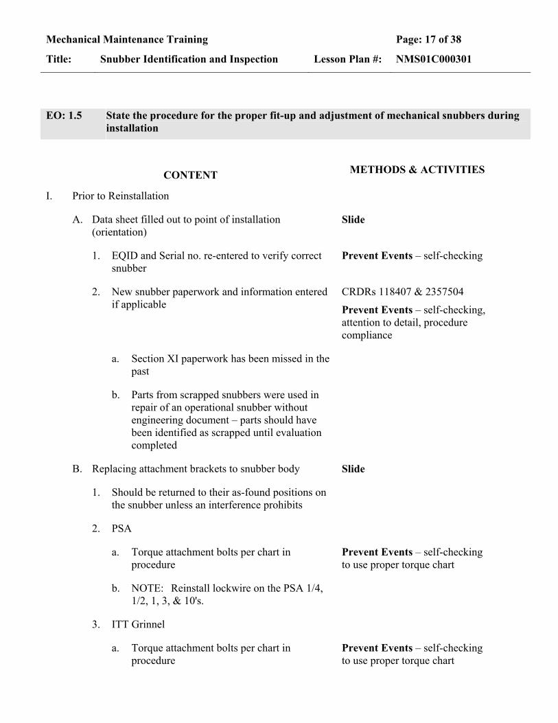
EO: 1.5 State the procedure for the proper fit-up and adjustment of mechanical snubbers during installation
CONTENT METHODS & ACTIVITIES
I. Prior to Reinstallation
A. Data sheet filled out to point of installation (orientation)
Slide
1. EQID and Serial no. re-entered to verify correct snubber
Prevent Events – self-checking
2. New snubber paperwork and information entered if applicable
CRDRs 118407 & 2357504
Prevent Events – self-checking, attention to detail, procedure compliance
a. Section XI paperwork has been missed in the past
b. Parts from scrapped snubbers were used in repair of an operational snubber without engineering document – parts should have been identified as scrapped until evaluation completed
B. Replacing attachment brackets to snubber body Slide
1. Should be returned to their as-found positions on the snubber unless an interference prohibits
2. PSA
a. Torque attachment bolts per chart in procedure
Prevent Events – self-checking to use proper torque chart
b. NOTE: Reinstall lockwire on the PSA 1/4, 1/2, 1, 3, & 10's.
3. ITT Grinnel
a. Torque attachment bolts per chart in procedure
Prevent Events – self-checking to use proper torque chart

Mechanical Maintenance Training Page: 18 of 38
Title: Snubber Identification and Inspection Lesson Plan #: NMS01C000301
CONTENT METHODS & ACTIVITIES
b. PSA 35 values are in ft-lbs and are for the threaded pipe or pivot mount
Slide
C. Final stroke test
1. Stroke test must be done at the installation location prior to installing the last load stud/pin,
2. Ensure snubber moves through its full length
II. Fit-up of Mechanical Snubbers
A. Caution notes:
1. Use care to align snubbers as closely as possible to avoid forces tending to rotate the pipe clamp or induce bending.
2. If a snubber is accidentally dropped, a functional test must be performed in accordance with 73ST-9ZZ22.
3. When installing the load pin or the load stud avoid driving the spherical bearing free or damaging the bearings. Pins should be snug but not tight.
4. Do not attempt to rotate the end caps to align the snubber.
Demonstrate on Training aids (any snubber).
B. Fit-up
1. In most cases when replacing the snubber body proper orientation of the attachment brackets with the snubber end cap assembly should be all that is necessary. However, if alignment is needed perform the following.
2. PSA 1/4 through #10
a. Remove the attachment brackets. Slide
b. Place the snubber in the vertical position (housing down)
Use training aid to demonstrate
Mechanical Maintenance Training Page: 19 of 38
Title: Snubber Identification and Inspection Lesson Plan #: NMS01C000301
CONTENT METHODS & ACTIVITIES
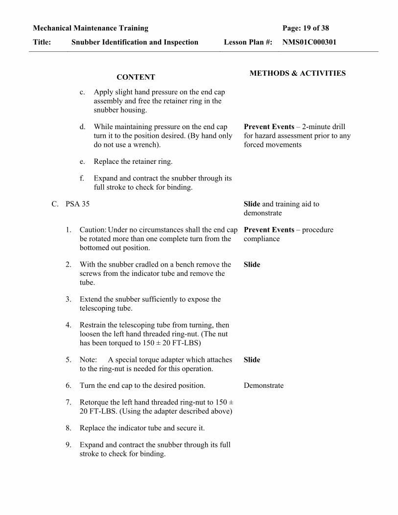
c. Apply slight hand pressure on the end cap assembly and free the retainer ring in the snubber housing.
d. While maintaining pressure on the end cap turn it to the position desired. (By hand only do not use a wrench).
Prevent Events – 2-minute drill for hazard assessment prior to any forced movements
e. Replace the retainer ring.
f. Expand and contract the snubber through its full stroke to check for binding.
C. PSA 35 Slide and training aid to demonstrate
1. Caution: Under no circumstances shall the end cap be rotated more than one complete turn from the bottomed out position.
Prevent Events – procedure compliance
2. With the snubber cradled on a bench remove the screws from the indicator tube and remove the tube.
Slide
3. Extend the snubber sufficiently to expose the telescoping tube.
4. Restrain the telescoping tube from turning, then loosen the left hand threaded ring-nut. (The nut has been torqued to 150 ± 20 FT-LBS)
5. Note: A special torque adapter which attaches to the ring-nut is needed for this operation.
Slide
6. Turn the end cap to the desired position. Demonstrate
7. Retorque the left hand threaded ring-nut to 150 ± 20 FT-LBS. (Using the adapter described above)
8. Replace the indicator tube and secure it.
9. Expand and contract the snubber through its full stroke to check for binding.
Mechanical Maintenance Training Page: 20 of 38
Title: Snubber Identification and Inspection Lesson Plan #: NMS01C000301
CONTENT METHODS & ACTIVITIES
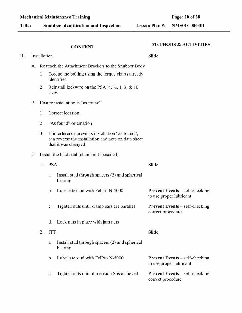
III. Installation Slide
A. Reattach the Attachment Brackets to the Snubber Body
1. Torque the bolting using the torque charts already identified
2. Reinstall lockwire on the PSA ¼, ½, 1, 3, & 10 sizes
B. Ensure installation is “as found”
1. Correct location
2. “As found” orientation
3. If interference prevents installation “as found”, can reverse the installation and note on data sheet that it was changed
C. Install the load stud (clamp not loosened)
1. PSA Slide
a. Install stud through spacers (2) and spherical bearing
b. Lubricate stud with Felpro N-5000 Prevent Events – self-checking to use proper lubricant
c. Tighten nuts until clamp ears are parallel Prevent Events – self-checking correct procedure
d. Lock nuts in place with jam nuts
2. ITT Slide
a. Install stud through spacers (2) and spherical bearing
b. Lubricate stud with FelPro N-5000 Prevent Events – self-checking to use proper lubricant
c. Tighten nuts until dimension S is achieved Prevent Events – self-checking correct procedure

Mechanical Maintenance Training Page: 21 of 38
Title: Snubber Identification and Inspection Lesson Plan #: NMS01C000301
CONTENT METHODS & ACTIVITIES
d. Lock nuts in place with jam nuts
D. Install the load pin
1. Push the pin through the rear bracket, spacer/washers and spherical bearing.
a. Washers/spacers are only required if there is a gap – The spec allows omitting them if not needed
b. On 3, 10, & 35 KIP snubbers that have a thin washer, do not reinstall the washers
(1) The washers drop into the threads of the load stud
(2) The load stud becomes destroyed when trying to remove it
2. Secure in place with cotter pins or spring clips.
IV. Replacement of the pipe clamp brackets (if removed/loosened)
A. PSA Slide for the PSA discussion Prevent Events – self-checking correct procedure
1. All load studs, load stud spacers and jam nuts (used for the attaching the snubber) are made of stainless steel.
2. Bolts and Studs
a. Pipe clamps used with snubber models 1/4 through #10 use bolts rather than studs except for the load stud that attaches to the snubber.
b. Clamps for the 35 model use studs in all locations.
3. Regardless of the orientation of snubber installation, the pipe clamp end with the load stud is the top end of the clamp

Mechanical Maintenance Training Page: 22 of 38
Title: Snubber Identification and Inspection Lesson Plan #: NMS01C000301
CONTENT METHODS & ACTIVITIES
4. Place the clamp body halves on the pipe and insert the inner bolt/stud through clamp and pipe spacer and install the nuts loosely.
Slide
5. Insert the bottom bolt/stud and install the nuts loosely.
6. Insert the load stud through the spacer/washers and the spherical bearing of the snubber and install the nuts loosely.
7. Check the clamp alignment then tighten the inner bolt/stud to the specified torque value
8. Tighten the bottom bolt/stud to minimum torque per Table 1.
a. If the B-B dimension between the bottom ears is equal to or smaller than the B-B dim. at the pipe spacer, do not tighten the bottom bolt/stud any further.
b. If the B-B dimension is larger, continue to tighten the bottom bolt/stud until the ears are parallel.
9. Tighten the load stud until the top end ears are parallel, or until the spacer/washers are snug against the spherical bearing.
10. Lock all the jam nuts in place.
11. Check to assure that the snubber is free to pivot about the load stud. The clamp body must not interfere with the snubber end
B. ITT Slide Prevent Events – self-checking correct procedure
1. Install load stud nuts until the ‘S’ dimension specified, then lock in place with jam nuts (about 1/8 turn past finger tight)
2. Tighten upper clamp bolt wrench tight

Mechanical Maintenance Training Page: 23 of 38
Title: Snubber Identification and Inspection Lesson Plan #: NMS01C000301
CONTENT METHODS & ACTIVITIES
3. Tighten lower clamp bolt until clamp is firmly against the pipe – either 2 point or 4-point contact is acceptable
Slide Point out what this means on the slide
V. Finish Documentation
A. Perform post-installation visual inspection
B. Complete documentation for Removal/Installation
C. Partial detachment/reattachment
1. Similar to complete
2. Still requires same information prior to disconnecting
3. Requires same information when reconnected
a. Exception – attachment information
b. Since it was not removed at one end, the orientation should not change, but it is still checked

Mechanical Maintenance Training Page: 24 of 38
Title: Snubber Identification and Inspection Lesson Plan #: NMS01C000301
EO: 1.6 State the normal and post-transient inspection criteria and the data recorded for hydraulic snubbers
CONTENT METHODS & ACTIVITIES
I. Data Sheet (note that all but the serial number is given) Slide
A. EQID & suffix to identify location Prevent Events – self-check to ensure you are on the correct component and logging the information on the correct line of the data sheet
B. Size and model number
C. Serial number
D. Condition Codes
1. Relate to the inspection criteria
2. Identify by code the items that are not satisfactory
II. Why Perform Inspection?
A. Scheduled inspection
B. Potentially damaging transient (within 6 months)
C. Inspect for:
1. Verify there is no physical damage/wear
2. Verify the oil is good
III. Inspection Criteria Letters in parenthesis are the code on the inspection sheet to enter if not acceptable
A. No visible leaks (EL) Note that this is one of the most common problems with the hydraulic snubbers
1. Plugs
Mechanical Maintenance Training Page: 25 of 38
Title: Snubber Identification and Inspection Lesson Plan #: NMS01C000301
CONTENT METHODS & ACTIVITIES
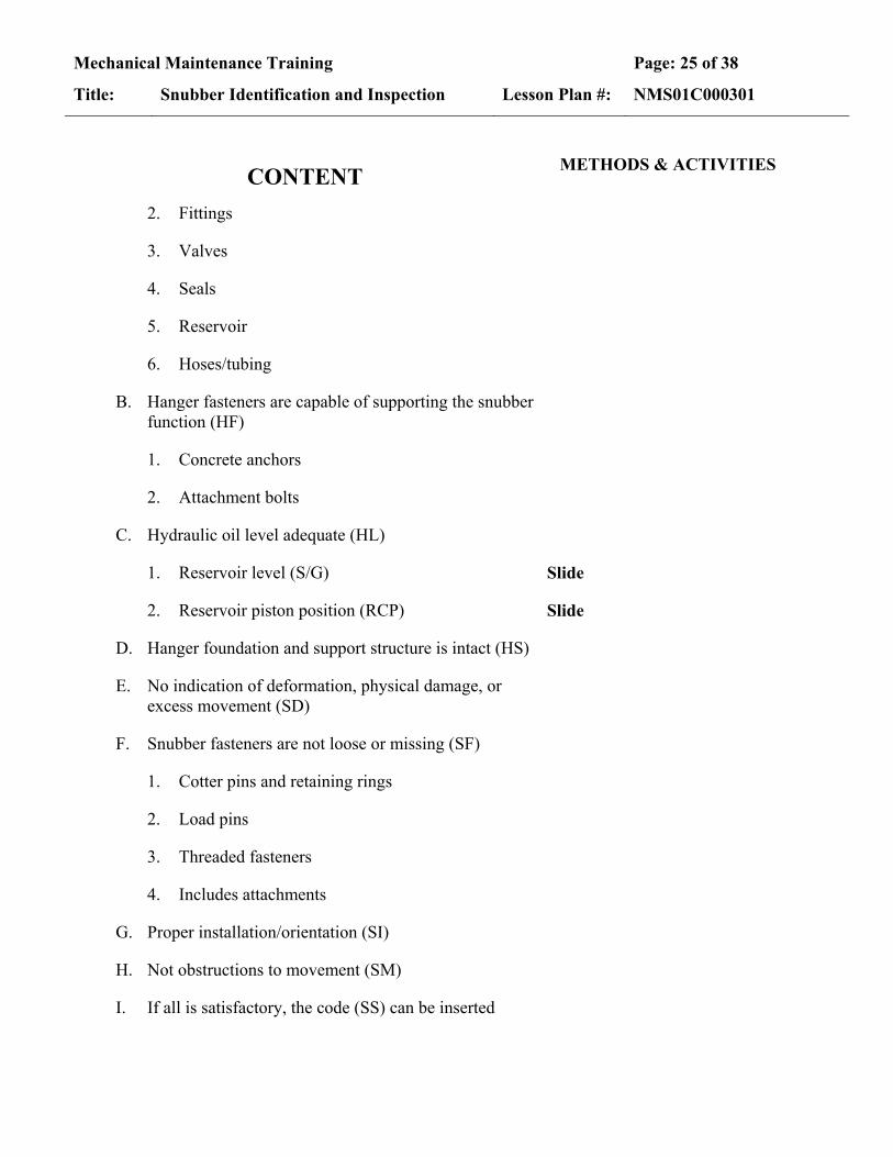
2. Fittings
3. Valves
4. Seals
5. Reservoir
6. Hoses/tubing
B. Hanger fasteners are capable of supporting the snubber function (HF)
1. Concrete anchors
2. Attachment bolts
C. Hydraulic oil level adequate (HL)
1. Reservoir level (S/G) Slide
2. Reservoir piston position (RCP) Slide
D. Hanger foundation and support structure is intact (HS)
E. No indication of deformation, physical damage, or excess movement (SD)
F. Snubber fasteners are not loose or missing (SF)
1. Cotter pins and retaining rings
2. Load pins
3. Threaded fasteners
4. Includes attachments
G. Proper installation/orientation (SI)
H. Not obstructions to movement (SM)
I. If all is satisfactory, the code (SS) can be inserted

Mechanical Maintenance Training Page: 26 of 38
Title: Snubber Identification and Inspection Lesson Plan #: NMS01C000301
EO: 1.7 State the major steps in the 5 and 10 year surveillance tests of the S/G and RCP hydraulic snubbers
CONTENT METHODS & ACTIVITIES
Refer to current revision of 73ST-9ZZ10 as necessary for any additional information and questions
I. 5 year Surveillance Test (RCP) Use T018 to illustrate the discussion of the Sample procedure
A. Basic Purpose – 73ST-9ZZ23
1. Sample the hydraulic fluid for water and particulates
2. Replace the hydraulic fluid with new fluid if necessary
a. Planned after 10 years
b. Allowed to re-use the fluid if it meets specifications
3. NOTE:
a. Cleanliness is paramount whenever opening a hydraulic system.
b. Clean plug exteriors and take special precautions to keep contaminants out.
c. FME controls in effect as required
Prevent Events – 2-minute drill, keeping dirt out whenever opening or closing ports NOTE: Add that the tech spec indicates that if the plugs are ever found removed, the snubber WILL BE DECLARED INOPERABLE!!
B. Set up the area
1. Oil absorbent under the snubber to catch any hydraulic fluid that leaks
2. Inspect for any evidence of existing leakage
3. Replacement O-rings available [verify parts]
Mechanical Maintenance Training Page: 27 of 38
Title: Snubber Identification and Inspection Lesson Plan #: NMS01C000301
CONTENT METHODS & ACTIVITIES
C. Water/Viscosity Sample
1. Control Room must be notified of the potential for an alarm on the snubber prior to taking sample
Prevent Events – 3-leg communication to ensure control room is aware and knows which snubber
2. Plastic hose is connected to the quick disconnect port (e)
3. 400 ml sample is removed from port (e) and analyzed for water and viscosity (resistance to flow)
If necessary, let them know that the water floats on top of this type of hydraulic fluid--that's why the sample is drawn from the top
4. This process depressurizes the snubber as well as draws the sample
D. Particulate sample
1. 200 ml sample taken from port (d)
2. Plug is loosened, not removed.
E. Drain the reservoir and cylinder
1. Pump hooked up to quick disconnect port (e)
2. Vent & Drain plugs removed and fluid drained into a container
Show drains (c) & (d) and vents (a) and (b) on Slide
3. When reservoir rod is bottomed, it is fully drained
4. Plugs replaced for FME
F. If oil samples are not acceptable, the snubber is flushed
1. Use EPA 2000
2. Pump through the fill plug on side
3. Drained from bottom (RCP only)

Mechanical Maintenance Training Page: 28 of 38
Title: Snubber Identification and Inspection Lesson Plan #: NMS01C000301
CONTENT METHODS & ACTIVITIES
G. Replacement of fluid Point out the parts on Slide as mentioned
1. New O-rings installed in plugs (c) and (d) and plugs torqued
a. Removal of old O-rings may require careful prying without damaging the sealing surface surrounding the hole
b. If O-ring is being removed without draining the cylinder, plug the hole with a long bolt to minimize leakage while prying the O-ring off
c. Ensure O-ring is seated (hand-tight) prior to tightening with a wrench
Mention ways this has been done – scraper or shim holding it up while tightening down by hand
2. Cylinder filled with fluid through ports (f) and (g)
3. Plugs with new O-rings installed and torqued Prevent Events – 2-minute drill for hazards of dirt and leak potential
4. Reservoir filled through ports (a) and (b), then plugs installed with new O-rings and torqued
Prevent Events – 2-minute drill for hazards of dirt and leak potential
5. Finish filling using hand pump until the piston rod extends to length of 12" ± 1"
a. Connected at the quick disconnect port (e)
b. Hose must be bled of all air first
c. 5 micron filter installed in the line to keep out any particulates
6. Retract the piston
a. Valve on hand pump is used to return the piston to the distance shown on the drawing
Show the Fluid Level Range on Slide
b. This process vents air out of the reservoir

Mechanical Maintenance Training Page: 29 of 38
Title: Snubber Identification and Inspection Lesson Plan #: NMS01C000301
CONTENT METHODS & ACTIVITIES
II. 5 year Surveillance Test (S/G) Use Slide and show the parts of the snubber as they are discussed
A. Same general process
B. Set up the area
1. Oil absorbent under the snubber to catch any hydraulic fluid that leaks (open grating)
2. Inspect for any evidence of existing leakage
3. Replacement O-rings available
C. Ports numbers are different from RCP
D. Differences in samples
1. The sediment, water and viscosity samples are all taken from the bottom port (f)
2. 600 ml sample size
3. Sample is taken without removing the plug
a. Cannot depressurize without draining the reservoir
Note: it may be possible with a vacuum – not verified yet
b. A hole in the plug will allow oil to come out without removal of the plug
c. When turning the plug, oil will shoot out, revolving 360º around – makes a big mess
4. O-ring of the plug is replaced if a sample is drawn, even though the fluid is not completely drained.
Prevent Events – 2-minute drill for hazards of dirt and leak potential
E. Draining (If required by sample) Prevent Events – 2-minute drill for hazards of dirt and leak potential upon reinstallation
1. Reservoir drained by disconnecting the flexible hose from the external snubber tubing

Mechanical Maintenance Training Page: 30 of 38
Title: Snubber Identification and Inspection Lesson Plan #: NMS01C000301
CONTENT METHODS & ACTIVITIES
2. Plugs (a), (b), (c), (d), (e), and (f) are all removed to drain the hydraulic cylinder
3. Plugs (e) and (f) are replaced immediately for cleanliness
4. Snubber flushed
F. Refilling fluid
1. Filled with Fyrquel GT hydraulic fluid
2. Cylinders filled through (b) and (c)
3. New O-rings installed and plugs replaced Can review O-ring cautions again if desired
a. Removal of old O-rings may require careful prying without damaging the sealing surface surrounding the hole
b. If O-ring is being removed without draining the cylinder, plug the hole with a long bolt to minimize leakage while prying the O-ring off
c. Ensure O-ring is seated (hand-tight) prior to tightening with a wrench
Mention ways this has been done – scraper or shim holding it up while tightening down by hand
4. Fluid is then added through tubing until it flows from (a) and (d)
5. O-rings replaced and plugs torqued Prevent Events – 2-minute drill for hazards of dirt and leak potential
6. Reservoir is filled through breather cap with flex hose plugged
7. Air is bled from the flex hose by unplugging it
8. Finish bleeding through (a) and (d) after hooking up the hose

Mechanical Maintenance Training Page: 31 of 38
Title: Snubber Identification and Inspection Lesson Plan #: NMS01C000301
CONTENT METHODS & ACTIVITIES
III. 10 Year Surveillance Test (RCP)
A. Take samples (similar to 5 year)
B. Replace Chevron Pack
1. Wiper retainer, retainer, rod wiper, chevron pack, and wave spring are removed by removing screws from rod head of cylinder
2. Packing bores are cleaned and all dirt and grime are removed from the piston rod
3. New wave springs and Chevron packs are installed using a Teflon probe (rod) to push them in
4. If the chevron packing is solid, it must be cut on a 45° diagonal and the cuts staggered by 30°
5. Replace retainer, rod wiper, and wiper retainer, securing with screws
C. Replacement of Reservoir Rod Wiper
1. Retaining ring is removed from the end of the reservoir
2. Rod wiper, rod head, rod seal and head seal are removed
3. DO NOT REMOVE THE INNER RETAINING RING
4. Inspect seals--if seals are not damaged, they can be reused
5. Clean and inspect bore and rod
6. Reinstall rod and head seals
7. Refill as in the 5-year surveillance test Review with class if necessary

Mechanical Maintenance Training Page: 32 of 38
Title: Snubber Identification and Inspection Lesson Plan #: NMS01C000301
CONTENT METHODS & ACTIVITIES
IV. 10 Year Surveillance Test (S/G)
A. Sample and drain as in the 5-year surveillance test
B. Replace chevron packing as on the RCP snubber 10 year surveillance
C. Refill as in the 5-year surveillance test
V. Functional Test (RCP) 73ST-9ZZ10 Tech Spec 4.7.9.f
A. Responsibilities of mechanic
1. Assist Vendor with setup and restoration
2. Coordinate installation of scaffolding
3. Hookup and removal of test equipment to snubbers
Prevent Events – 2-minute drill for hazards of dirt and leak potential
4. Removal/installation of RCP clevis pins
a. Force must be removed from the pin
b. Will possibly require pumping to adjust the piston
5. Provide certified rigging equipment and tools as needed
B. Basic setup
1. Hydraulic snubbers are tested in place
2. On the RCP's, the inside clevis pin (one closest to the motor) is removed and supported with rigging during the tests
Prevent Events – PJB on methods to remove pin without damaging it

Mechanical Maintenance Training Page: 33 of 38
Title: Snubber Identification and Inspection Lesson Plan #: NMS01C000301
CONTENT METHODS & ACTIVITIES
C. Lockup and Release Rate (Bleedrate) in Tension (RCP)
1. What it is
a. Lockup – the flow rate required to shut the control valve
b. Release Rate (Bleedrate) – the rate of flow through the orifice after the control valve has shut
2. Set up the snubber for the test
a. The reservoir is depressurized thru port "e"
b. Install temporary reservoir rod restraining device
c. Plugs f & g are removed and the vendor supplied 3/8” couplers are installed
d. The Barker/Diacon IPST-10 test machine supply line is hooked to port "g" and the return line to port "f" through Vendor supplied fittings
Barker/Diacon IPST-10 test
machine
e. The snubber is fully retracted using the test machine
3. Lockup (valve closure) Velocity and Bleedrate tests "in tension" are performed and data recorded
D. Perform the same tests for compression
1. Reverse the supply and return hoses (supply "f", return "g")
2. Fully extend the snubber
3. Perform lockup velocity and bleedrate tests “in compression”

Mechanical Maintenance Training Page: 34 of 38
Title: Snubber Identification and Inspection Lesson Plan #: NMS01C000301
CONTENT METHODS & ACTIVITIES
E. Restore the snubber to operating condition
1. Reinstall bleed plugs with new O-rings
2. Torque the plugs
3. Remove the reservoir rod restraining device
4. Return the snubber to the “as-found” dimension
F. Reservoir is refilled with qualified GE SF-1154 oil thru port "e"
G. RCP clevis pins are reinstalled when complete
1. Piston will need to be extended/retracted as appropriate to align the clevis with the hole in the support stand
2. OE – Pin was damaged when this was not done
VI. Functional Test (S/G) Tech Spec 4.7.9.f
A. The testing is primarily the same as that performed on the RCP's
B. Exceptions
1. A seal integrity test is performed
2. The valve manifold is removed and the test performed off the snubber then the manifold is reinstalled
Prevent Events – 2-minute drill for hazards of dirt and leak potential
a. Care must be taken not to disturb the poppets on the control valve prior to testing
b. This would be considered pre-conditioning
c. FME plugs are installed where control valves were removed.
Mechanical Maintenance Training Page: 35 of 38
Title: Snubber Identification and Inspection Lesson Plan #: NMS01C000301
CONTENT METHODS & ACTIVITIES
C. Seal Integrity Test
1. Seal integrity test probes (fittings) are installed in the ports where the control valve test probes were installed
2. Test rig is hooked to the blind end test probe. The other probe is left open to atmosphere
3. Using hand pump, seals are pressurized to 15±5 psig
4. Valve is closed and pressure monitored for 5 minutes
5. Same test is done with the test rig to the rod end test probe
VII. General Maintenance Concerns
A. RCP snubbers
1. Leaks on plugged ports
a. O-rings are not seated properly (metal O-rings)
b. O-ring seating surfaces are damaged
2. Damaged load pins
a. Side loaded when removing
b. Trying to force the pin out
B. S/G snubbers
1. Leaks on plugged ports
a. Plug seals not seated properly
b. Seating surfaces damaged

Mechanical Maintenance Training Page: 36 of 38
Title: Snubber Identification and Inspection Lesson Plan #: NMS01C000301
CONTENT METHODS & ACTIVITIES
2. Removal of reservoir flex connection Prevent Events – pre-job and 2-minute drill prior to disconnecting the hose – hazard assessment
a. Extremely messy
b. Head pressure to the reservoir pushes out on the fitting
c. Must be ready to plug the fitting immediately Bring up the possibility of drawing a vacuum on the reservoir to minimize/eliminate the head pressure
d. Reconnecting is even worse – must align the fitting while oil is leaking out
e. Have adequate means for capture/cleanup to preclude hydraulic fluid dripping below

Mechanical Maintenance Training Page: 37 of 38
Title: Snubber Identification and Inspection Lesson Plan #: NMS01C000301
EO: 1.8 Perform classroom exercise of a visual inspection of a mechanical snubber
CONTENT METHODS & ACTIVITIES
I. Prepare for Lab Exercise Provide a copy of 73ST-9ZZ21 to students and walk them through a visual inspection and filling out the Appendix A
A. 2-minute drill
B. PPE expectations – gloves for handling Use Standards and Expectations and discuss
II. Nameplate Data
A. EQID
B. Snubber size
C. Serial No
III. Inspection Data
A. Damage
B. Fasteners secured
C. Welds intact
D. Swing clearance
IV. Verify freedom of movement – Post Transient, PSA ¼, ½, or 1

Mechanical Maintenance Training Page: 38 of 38
Title: Snubber Identification and Inspection Lesson Plan #: NMS01C000301
SUMMARY OF MAIN PRINCIPLES The following items are things to consider in your lesson summary. They are not mandatory.
Objectives Review
Review the Lesson Objectives Topic Review
Restate the main principles or ideas covered in the lesson. Relate key points to the objectives. Use a question and answer session with the objectives.
Questions and Answers
Ask questions that implement the objectives. Discuss students answers as needed to ensure the objectives are being met.
Concluding Statement
If not done in the previous step, review the motivational points that apply this lesson to students needs. Use this opportunity to address an impending exam or practical exercise.