Embed Size (px)
Citation preview

667
Related Information
Selection Guide
Pressure/Digital Display
Pressure/Head-separated
Flow
Other Products
DP-100
DP-M
FIBERSENSORS
LASERSENSORS
PHOTOELECTRICSENSORS
MICROPHOTOELECTRIC
SENSORS
AREASENSORS
LIGHTCURTAINS
PRESSURE / FLOW
SENSORSINDUCTIVEPROXIMITY
SENSORS
PARTICULARUSE SENSORS
SENSOROPTIONS
SIMPLEWIRE-SAVING
UNITS
WIRE-SAVING SYSTEMS
MEASUREMENTSENSORS
STATIC CONTROLDEVICES
ENDOSCOPE
LASERMARKERS
PLC /TERMINALS
HUMAN MACHINE INTERFACES
ENERGY CONSUMPTION VISUALIZATION COMPONENTS
FA COMPONENTS
MACHINE VISION SYSTEMS
UV CURING SYSTEMS
Conforming toEMC Directive
The dual display means that the “current value” and the “threshold value”, it makes direct setting of threshold valueEquipped with a 30 mm 1.181 in square compact-sized dual display. Because the current value and the threshold value can be checked at the same time, the threshold value can be set and checked smoothly without having to switch screen modes. ON / OFF operations are still carried out while the threshold values are being set, so setting to the same sensitivity as dial control-type sensors is possible. And naturally a key lock function is also equipped.
Digital Auto reference With analogoutput
Current value
Threshold valueMan-hours reduced by Man-hours reduced by 3/43/4
DP-100 with dual display
Previous model with single display
–91.8
Note current value
Thre
shol
d va
lue
setti
ng m
etho
d
Operate MODE key Adjust threshold value Return to RUN operation
Simply press a button during RUN operation
3-color display (Red, Green, Orange)The main display changes color in line with changes in the status of output ON / OFF operation, and it also changes color while setting is in progress. The sensor status can therefore be understood easily, and operating errors can be reduced.
SET: Orange OFF: Green (or Red) ON: Red (or Green)
During normal operation During setting
Main Display
Readable digital display12 segments are used and an alphanumeric display has been adopted. This improves visual checking of letters and numbers.
DP-100 SERIES
Dual 3-color display makes operation easier!
Certified[DP-101(A)/102(A) only]
Recognition
■General terms and conditions ........... F-17 ■Sensor selection guide ................. P.661~
■General precautions ..................... P.1405 ■Korea’s S-mark ............................. P.1410
* UL 61010C-1 compatible, Passed the UL 991 Environment Test based on SEMI S2-0200.[Category applicable for semiconductor manufacturing: TWW2, Process Equipment][Applicable standards: UL 61010C-1][Additional test / evaluation standards as per intended use: UL 991, SEMI S2-0200]
* Passed the UL 991 Environment Test
■SC-SU1........................................... P.917 ■Glossary of terms.......................... P.1373
Dual Display Digital Pressure Sensor For Gas
Phone: 800.894.0412 - Fax: 888.723.4773 - Web: www.clrwtr.com - Email: [email protected]
Dual Display Digital Pressure Sensor DP-100 SERIES 668
Selection GuidePressure/Digital DisplayPressure/Head-separated
Flow
Other Products
DP-100
DP-M
FIBERSENSORS
LASERSENSORS
PHOTOELECTRICSENSORS
MICROPHOTOELECTRICSENSORS
AREASENSORS
LIGHTCURTAINS
PRESSURE / FLOWSENSORSINDUCTIVEPROXIMITYSENSORS
PARTICULARUSE SENSORS
SENSOROPTIONS
SIMPLEWIRE-SAVINGUNITS
WIRE-SAVING SYSTEMS
MEASUREMENTSENSORS
STATIC CONTROLDEVICES
ENDOSCOPE
LASERMARKERS
PLC /TERMINALS
HUMAN MACHINE INTERFACES
ENERGY CONSUMPTION VISUALIZATION COMPONENTS
FA COMPONENTS
MACHINE VISION SYSTEMS
UV CURING SYSTEMS
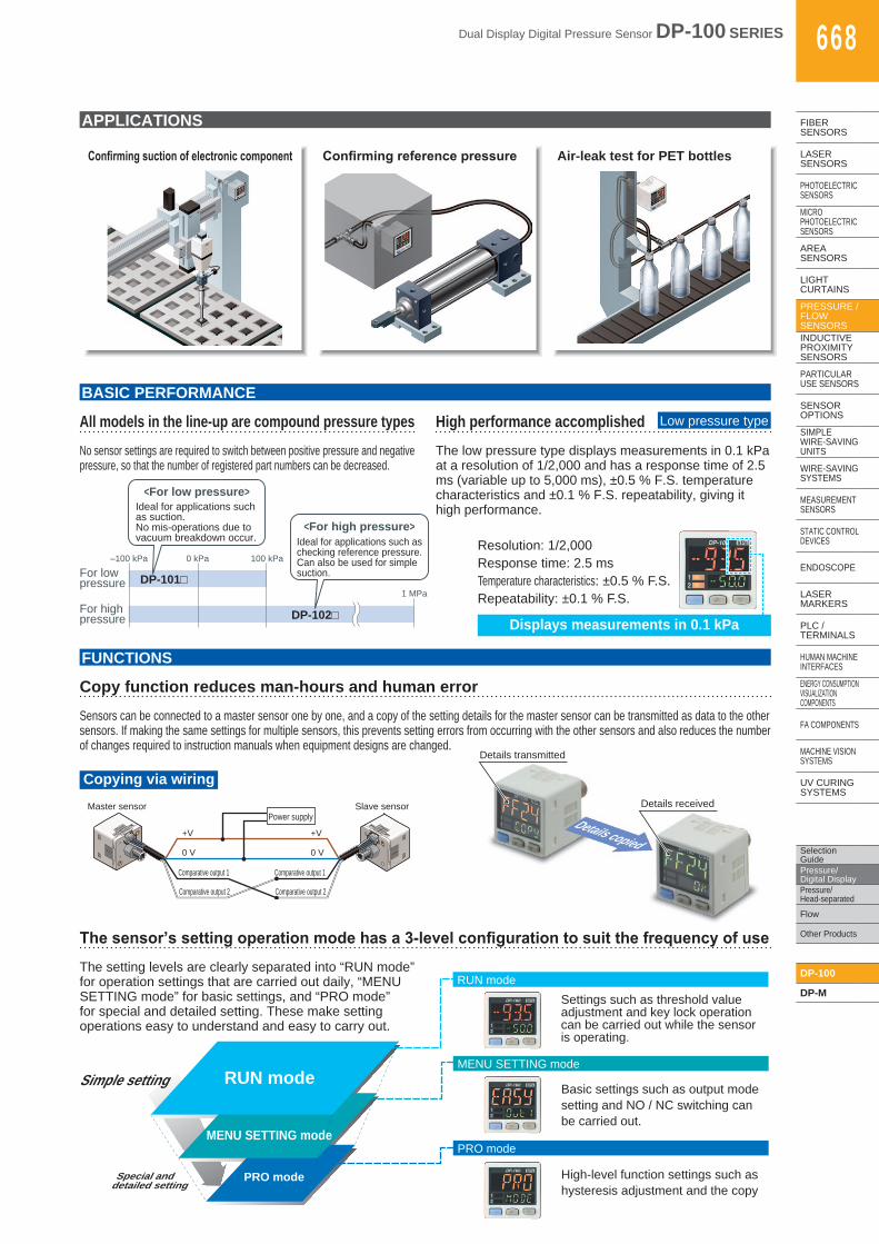
APPLICATIONS
Confirming suction of electronic component Confirming reference pressure Air-leak test for PET bottles
All models in the line-up are compound pressure typesNo sensor settings are required to switch between positive pressure and negative pressure, so that the number of registered part numbers can be decreased.
BASIC PERFORMANCE
FUNCTIONS
High performance accomplishedThe low pressure type displays measurements in 0.1 kPa at a resolution of 1/2,000 and has a response time of 2.5 ms (variable up to 5,000 ms), ±0.5 % F.S. temperature characteristics and ±0.1 % F.S. repeatability, giving it high performance.
Low pressure type
For lowpressure
<For low pressure>
For highpressure
DP-101□
DP-102□
–100 kPa 100 kPa
1 MPa
0 kPa
<For high pressure>Ideal for applications such as checking reference pressure. Can also be used for simple suction.
Ideal for applications suchas suction. No mis-operations due tovacuum breakdown occur. Resolution: 1/2,000
Response time: 2.5 ms Temperature characteristics: ±0.5 % F.S. Repeatability: ±0.1 % F.S.
Displays measurements in 0.1 kPa
Sensors can be connected to a master sensor one by one, and a copy of the setting details for the master sensor can be transmitted as data to the other sensors. If making the same settings for multiple sensors, this prevents setting errors from occurring with the other sensors and also reduces the number of changes required to instruction manuals when equipment designs are changed.
Copy function reduces man-hours and human error
Copying via wiring
+V
0 V
Comparative output 1
Comparative output 2
+V
0 V
Comparative output 1
Comparative output 2
Power supplySlave sensorMaster sensor
Details copied
Details transmitted
Details received
The setting levels are clearly separated into “RUN mode” for operation settings that are carried out daily, “MENU SETTING mode” for basic settings, and “PRO mode” for special and detailed setting. These make setting operations easy to understand and easy to carry out.
The sensor’s setting operation mode has a 3-level configuration to suit the frequency of use
Simple setting
Settings such as threshold value adjustment and key lock operation can be carried out while the sensor is operating.
Basic settings such as output mode setting and NO / NC switching can be carried out.
MENU SETTING mode
RUN mode
High-level function settings such as hysteresis adjustment and the copy
PRO mode
RUN mode
PRO mode
MENU SETTING mode
Special and detailed setting

669 Dual Display Digital Pressure Sensor DP-100 SERIES
Selection Guide
Pressure/Digital Display
Pressure/Head-separated
Flow
Other Products
DP-100
DP-M
FIBERSENSORS
LASERSENSORS
PHOTOELECTRICSENSORS
MICROPHOTOELECTRIC
SENSORS
AREASENSORS
LIGHTCURTAINS
PRESSURE / FLOW
SENSORSINDUCTIVEPROXIMITY
SENSORS
PARTICULARUSE SENSORS
SENSOROPTIONS
SIMPLEWIRE-SAVING
UNITS
WIRE-SAVING SYSTEMS
MEASUREMENTSENSORS
STATIC CONTROLDEVICES
ENDOSCOPE
LASERMARKERS
PLC /TERMINALS
HUMAN MACHINE INTERFACES
ENERGY CONSUMPTION VISUALIZATION COMPONENTS
FA COMPONENTS
MACHINE VISION SYSTEMS
UV CURING SYSTEMS
FUNCTIONS
Equipped with two independent comparative outputs, and separate sensing modes can be selected for each of them. Since there are two comparative outputs, one of the comparative outputs can even be used for alarm output. In addition, if an output is not being used, it can be disabled.
Equipped with independent dual output and three output modes Standard type
Comparative output 1 EASY mode
Comparative output 2 EASY mode
ON
OFF
ON
OFF
–100 kPa P-1 0 kPa P-2
Suction checking
Vacuum breakdown checking
Vacuum breakdown can also be checked during suction applications!
Reference pressure alarm output is possible during reference pressure checking!
0 kPa
Comparative output 1 hysteresis mode
Comparative output 2 EASY mode
ON
OFF
ON
OFF
Lo-1 Hi-1 P-2
Reference pressure checking
Alarm output
1 EASY mode
This mode is used for comparative output ON / OFF control.
H (Hysteresis)
H: Fixed
P
0ON
OFFComparative output
Pre
ssur
e
Notes:1)Hysteresiscanbefixedtooneofeightdifferentlevels.2) “ ”appears in the sub display for comparative output 1, and
“ ” appears for comparative output 2.
2 Hysteresis mode
This mode is used for setting comparative output hysteresis to the desired level and for carrying out ON / OFF control.
Lo
Hi
0ON
OFFComparative output
H (Hysteresis)
H: 1 digit or more
Pre
ssur
e
Note: “ ” or “ ” appears in the sub display for comparative output 1, and “ ” or “ ” appears for comparative output 2.
3 Window comparator mode
This mode is used for setting comparative output ON and OFF at pressures within the setting range.
H (Hysteresis)
H: Fixed
H (Hysteresis)
Comparative output
Lo
Hi
0ON
OFF
Pre
ssur
e
Notes:1)Hysteresiscanbefixedtooneofeightdifferentlevels.2) “ ” or “ ” appears in the sub display for comparative
output 1, and “ ” or “ ” appears for comparative output 2.
If the reference pressure of the device changes, the auto-reference function partially shift the comparative output judgment level by the amount that the reference pressure shifts, and the remote zero-adjustment function can reset thedisplayvaluetozeroviaexternalinput.Thesefunctionsareidealforplaceswherethereferencepressurefluctuateswildly,orwherefinesettingsare desired.
Equipped with auto-reference / remote zero-adjustment functions, more precise pressure management is possible with a minimum of effort Multi-function type
With auto-reference function applied
20
15
0
–5
OK
Comparative output: Window comparator modeHi-1…0, Lo-1…–5
When auto-reference input is applied, the reference pressure “30”is added to the threshold level. If the reference pressure changesto “20” or “40”, the auto-reference input compensates for thisevery time by changing the threshold level, so any variation inthe filling pressure can be ignored.
30
Auto-reference inputSets the absolute threshold level
The display remains at “30” andonly the threshold level is changed.
Threshold level before applyingauto-reference input
Trial 1
25
Time
PressureTrial 1
Auto-reference input value…
Comparative output: Window comparator modeHi-1…0, Lo-1…–5
Sets the absolute threshold level
With remote zero-adjustment function applied
20
15
0
–5
OK
When remote zero-adjustment input is applied, the referencepressure is forced to “0”. If the reference pressure changes to“20” or “40”, the remote zero-adjustment input adjusts thereference pressure to “0” every time the reference pressurechanges, so any variation in the filling pressure can be ignored.
30
Remote zero-adjustment input
Threshold level before applyingremote zero-adjustment input
Threshold level after applyingremote zero-adjustment input
25
Time
PressureDisplayed when remote zero-adjustment
input is applied…
–5
The display is forced to “0”, and only thefilling pressure drop range is displayed.
0
Threshold level after applyingauto-reference input
Dual Display Digital Pressure Sensor DP-100 SERIES 670
Selection GuidePressure/Digital DisplayPressure/Head-separated
Flow
Other Products
DP-100
DP-M
FIBERSENSORS
LASERSENSORS
PHOTOELECTRICSENSORS
MICROPHOTOELECTRICSENSORS
AREASENSORS
LIGHTCURTAINS
PRESSURE / FLOWSENSORSINDUCTIVEPROXIMITYSENSORS
PARTICULARUSE SENSORS
SENSOROPTIONS
SIMPLEWIRE-SAVINGUNITS
WIRE-SAVING SYSTEMS
MEASUREMENTSENSORS
STATIC CONTROLDEVICES
ENDOSCOPE
LASERMARKERS
PLC /TERMINALS
HUMAN MACHINE INTERFACES
ENERGY CONSUMPTION VISUALIZATION COMPONENTS
FA COMPONENTS
MACHINE VISION SYSTEMS
UV CURING SYSTEMS
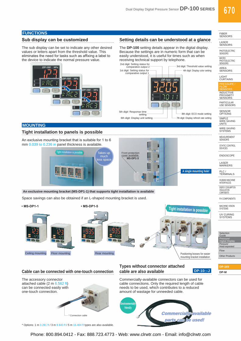
FUNCTIONS
The sub display can be set to indicate any other desired values or letters apart from the threshold value. This eliminatestheneedfortaskssuchasaffixingalabeltothe device to indicate the normal pressure value.
Sub display can be customizedThe DP-100 setting details appear in the digital display. Because the settings are in numeric form that can be easily understood, it is useful for times such as when receiving technical support by telephone.
Setting details can be understood at a glance
1st digit: Setting status for comparative output 1
5th digit: Response time setting
6th digit: Display unit setting 7th digit: Display refresh rate setting 8th digit: ECO mode setting
2nd digit: Setting status for comparative output 2 3rd digit: Threshold value setting
4th digit: Display color setting
MOUNTING
Anexclusivemountingbracketthatissuitablefor1to6mm 0.039 to 0.236 in panel thickness is available.
Tight installation to panels is possible
Takes up much
less space
Tight installation is possible Front protection cover available
MS-DP1-3
An exclusive mounting bracket (MS-DP1-1) that supports tight installation is available
Space savings can also be obtained if an L-shaped mounting bracket is used.
Cable can be connected with one-touch connection
* Connection cable
The accessory connector attached cable (2 m 6.562 ft) can be connected easily with one-touch connection.
Commercially-available connectors can be used for cable connections. Only the required length of cable needs to be used, which contributes to a reduced amount of wastage for unneeded cable.
A single mounting hole!
* Options: 1 m 3.281 ft / 3 m 9.843 ft / 5 m 16.404 ft types are also available.
• MS-DP1-1 • MS-DP1-5
Ceiling mounting Floor mounting Rear mounting Positioning bosses for easier mounting bracket installation
Tight installation is possible
Types without connector attached cable are also available DP-10□-J
Environmentallyfriendly
Commercially-availableparts can be used!
Commercially-availableparts can be used!
Phone: 800.894.0412 - Fax: 888.723.4773 - Web: www.clrwtr.com - Email: [email protected]
671 Dual Display Digital Pressure Sensor DP-100 SERIES
FIBERSENSORS
LASERSENSORS
PHOTO-ELECTRICSENSORS
MICROPHOTO-
ELECTRICSENSORS
AREASENSORS
LIGHTCURTAINS
PRESSURE / FLOW
SENSORS
INDUCTIVEPROXIMITY
SENSORS
PARTICULARUSE
SENSORS
SENSOROPTIONS
SIMPLEWIRE-SAVING
UNITS
WIRE-SAVING SYSTEMS
MEASURE-MENT
SENSORS
STATIC CONTROLDEVICES
ENDOSCOPE
LASERMARKERS
PLC /TERMINALS
HUMAN MACHINE
INTERFACESENERGY
CONSUMPTION VISUALIZATION COMPONENTS
FA COMPONENTS
MACHINE VISION
SYSTEMS
UV CURING
SYSTEMS
Selection Guide
Pressure/Digital Display
Pressure/Head-separated
Flow
Other Products
DP-100
DP-M
M8 connector
G 1/8 male threadM5 female thread
Mating cableCN-24A-C2 (cable length 2 m 6.562 ft)CN-24A-C5 (cable length 5 m 16.404 ft)
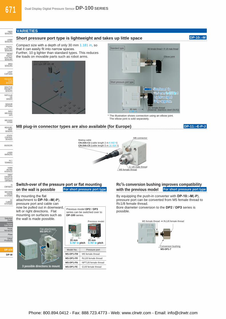
M8 piug-in connector types are also available (for Europe)
Switch-over of the pressure port or flat mounting on the wall is possible
Rc1/8 conversion bushing improves compatibility with the previous model
DP-11□-E-P-J
For short pressure port type For short pressure port type
VARIETIES
* The illustration shows connection using an elbow joint. The elbow joint is sold separately.
Compact size with a depth of only 30 mm 1.181 in, so thatitcaneasilyfitintonarrowspaces.Further, 10 g lighter than standard types. This reduces the loads on movable parts such as robot arms.
Bymountingtheflatattachment to DP-10□-M(-P), pressure port and cable can now be pulled out in downward, left or right directions. Flat mounting on surfaces such as the wall is made possible.
By equipping the push-in converter with DP-10□-M(-P), pressure port can be converted from M5 female thread to Rc1/8 female thread. Bore diameter conversion to the DP2 / DP3 series is possible.
Short pressure port type is lightweight and takes up little space DP-10□-M
Standard type
Short pressure port type
Shortened to 12.5 mm 0.492 in ! Light weight 30g approx.
Shortened to 12.5 mm 0.492 in ! Light weight 30g approx.
M5 female thread + R 1/8 male thread
Elbow joint
M5 female thread[Material: Stainless steel (SUS)]30 mm
1.181 in
Short pressure port type DP-10□-M
MS-DP1-7
M5 female thread Rc1/8 female thread
Conversion bushing
Flat attachment
3 possible directions to mount
MS-DP1-F□
20 mm0.787 in pitch
Previous model
Model No. Pressure port
MS-DP1-FM
MS-DP1-FR
MS-DP1-FN
MS-DP1-FE
M5 female thread
Rc1/8 female thread
NPT1/8 female thread
G1/8 female thread
Previous model DP2 / DP3 series can be switched over to DP-100 series.
20 mm0.787 in pitch
Phone: 800.894.0412 - Fax: 888.723.4773 - Web: www.clrwtr.com - Email: [email protected]
Dual Display Digital Pressure Sensor DP-100 SERIES 672
FIBERSENSORS
LASERSENSORS
PHOTO-ELECTRICSENSORSMICROPHOTO-ELECTRICSENSORS
AREASENSORS
LIGHTCURTAINS
PRESSURE / FLOWSENSORS
INDUCTIVEPROXIMITYSENSORS
PARTICULARUSE SENSORS
SENSOROPTIONS
SIMPLEWIRE-SAVINGUNITS
WIRE-SAVING SYSTEMS
MEASURE-MENTSENSORS
STATIC CONTROLDEVICES
ENDOSCOPE
LASERMARKERS
PLC /TERMINALS
HUMAN MACHINE INTERFACESENERGY CONSUMPTION VISUALIZATION COMPONENTS
FA COMPONENTS
MACHINE VISION SYSTEMS
UV CURING SYSTEMS
Selection GuidePressure/Digital DisplayPressure/Head-separated
Flow
Other Products
DP-100
DP-M
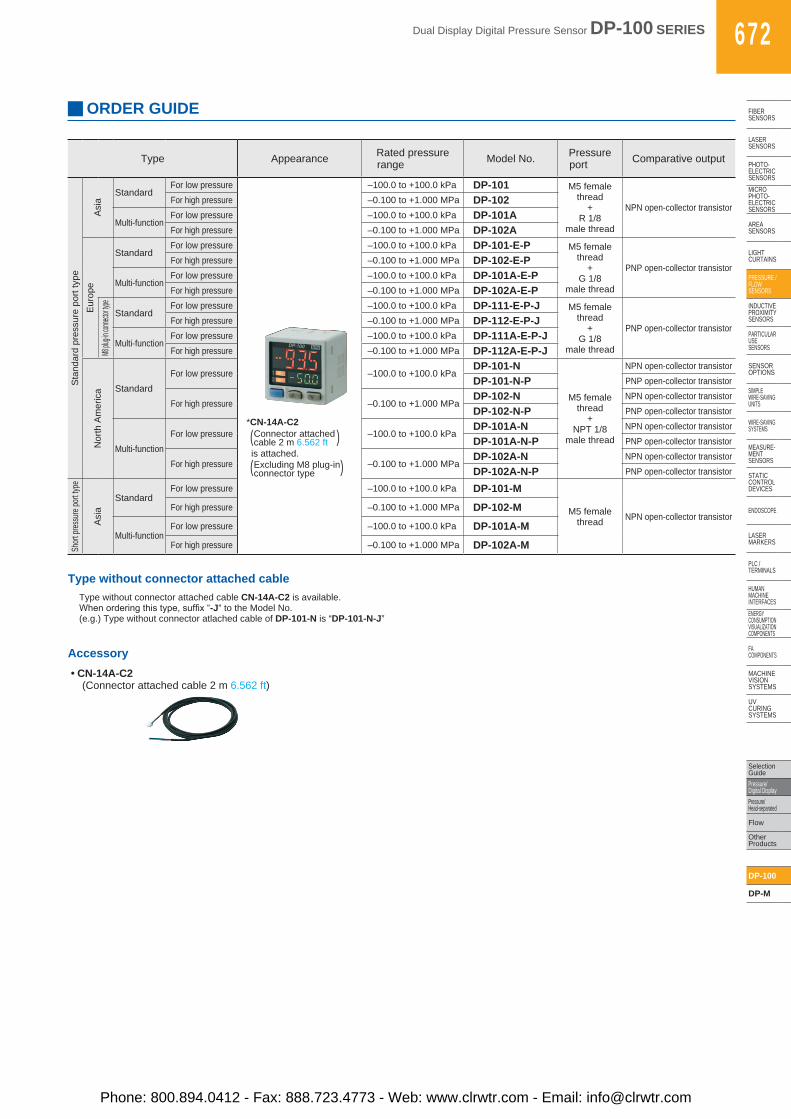
ORDER GUIDE
Type Appearance Rated pressure range Model No. Pressure
port Comparative output
Sta
ndar
d pr
essu
re p
ort t
ype
Asi
a
StandardFor low pressure
*CN-14A-C2
( )
( )
Connector attached cable 2 m 6.562 ft is attached. Excluding M8 plug-in connector type
–100.0 to +100.0 kPa DP-101 M5 female thread
+R 1/8
male thread
NPN open-collector transistorFor high pressure –0.100 to +1.000 MPa DP-102
Multi-functionFor low pressure –100.0 to +100.0 kPa DP-101AFor high pressure –0.100 to +1.000 MPa DP-102A
Eur
ope
StandardFor low pressure –100.0 to +100.0 kPa DP-101-E-P M5 female
thread+
G 1/8male thread
PNP open-collector transistorFor high pressure –0.100 to +1.000 MPa DP-102-E-P
Multi-functionFor low pressure –100.0 to +100.0 kPa DP-101A-E-PFor high pressure –0.100 to +1.000 MPa DP-102A-E-P
M8 plu
g-in co
nnecto
r type
StandardFor low pressure –100.0 to +100.0 kPa DP-111-E-P-J M5 female
thread+
G 1/8male thread
PNP open-collector transistorFor high pressure –0.100 to +1.000 MPa DP-112-E-P-J
Multi-functionFor low pressure –100.0 to +100.0 kPa DP-111A-E-P-JFor high pressure –0.100 to +1.000 MPa DP-112A-E-P-J
Nor
th A
mer
ica Standard
For low pressure –100.0 to +100.0 kPaDP-101-N
M5 female thread
+NPT 1/8
male thread
NPN open-collector transistor
DP-101-N-P PNP open-collector transistor
For high pressure –0.100 to +1.000 MPaDP-102-N NPN open-collector transistor
DP-102-N-P PNP open-collector transistor
Multi-functionFor low pressure –100.0 to +100.0 kPa
DP-101A-N NPN open-collector transistor
DP-101A-N-P PNP open-collector transistor
For high pressure –0.100 to +1.000 MPaDP-102A-N NPN open-collector transistor
DP-102A-N-P PNP open-collector transistor
Short
pres
sure
port t
ype
Asi
a
StandardFor low pressure –100.0 to +100.0 kPa DP-101-M
M5 female thread NPN open-collector transistor
For high pressure –0.100 to +1.000 MPa DP-102-M
Multi-functionFor low pressure –100.0 to +100.0 kPa DP-101A-MFor high pressure –0.100 to +1.000 MPa DP-102A-M
Type without connector attached cableType without connector attached cable CN-14A-C2 is available.Whenorderingthistype,suffix“-J” to the Model No.(e.g.) Type without connector atlached cable of DP-101-N is “DP-101-N-J”
Accessory• CN-14A-C2
(Connector attached cable 2 m 6.562 ft)
Phone: 800.894.0412 - Fax: 888.723.4773 - Web: www.clrwtr.com - Email: [email protected]
673 Dual Display Digital Pressure Sensor DP-100 SERIES
FIBERSENSORS
LASERSENSORS
PHOTO-ELECTRICSENSORS
MICROPHOTO-
ELECTRICSENSORS
AREASENSORS
LIGHTCURTAINS
PRESSURE / FLOW
SENSORS
INDUCTIVEPROXIMITY
SENSORS
PARTICULARUSE
SENSORS
SENSOROPTIONS
SIMPLEWIRE-SAVING
UNITS
WIRE-SAVING SYSTEMS
MEASURE-MENT
SENSORS
STATIC CONTROLDEVICES
ENDOSCOPE
LASERMARKERS
PLC /TERMINALS
HUMAN MACHINE
INTERFACESENERGY
CONSUMPTION VISUALIZATION COMPONENTS
FA COMPONENTS
MACHINE VISION
SYSTEMS
UV CURING
SYSTEMS
Selection Guide
Pressure/Digital Display
Pressure/Head-separated
Flow
Other Products
DP-100
DP-M
OPTIONS
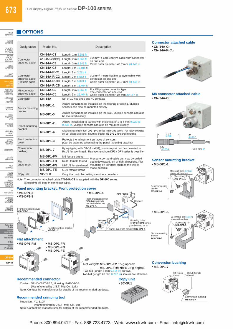
Recommended connectorContact: SPHD-001T-P0.5, Housing: PAP-04V-S
(Manufactured by J.S.T. Mfg.Co., Ltd.)Note: Contact the manufacturer for details of the recommended products.
Recommended crimping toolModel No.: YC-610R
(Manufactured by J.S.T. Mfg. Co., Ltd.)Note: Contact the manufacturer for details of the recommended products.
• MS-DP1-2• MS-DP1-3
• MS-DP1-4Panel mounting bracket, Front protection cover
Front protection coverMS-DP1-3
Panel mounting bracketMS-DP1-2
DP-100
Panel mounting bracket MS-DP1-4
DP2-20
ñ101.3kPa
OUT2
OUT1
MODE
0-ADJ
DP2 / DP3
Insert
Remove
Remove
Mounting holesfor DP2 / DP3 seriescan be used as is.
Front protection coverDPX-04 (optional)can be installed on MS-DP1-4.
Designation Model No. Description
Connector attached cable
CN-14A-C1 Length: 1 m 3.281 ft0.2 mm2 4-core cabtyre cable with connector on one endCable outer diameter: ø3.7 mm ø0.146 in
CN-14A-C2 (Note) Length: 2 m 6.562 ftCN-14A-C3 Length: 3 m 9.843 ftCN-14A-C5 Length: 5 m 16.404 ft
Connector attached cable (Flexiblecable)
CN-14A-R-C1 Length: 1 m 3.281 ft0.2 mm24-coreflexiblecabtyrecablewithconnector on one end Cable outer diameter: ø3.7 mm ø0.146 in
CN-14A-R-C2 Length: 2 m 6.562 ftCN-14A-R-C3 Length: 3 m 9.843 ftCN-14A-R-C5 Length: 5 m 16.404 ft
M8 connector attached cable
CN-24A-C2 Length: 2 m 6.562 ft For M8 plug-in connector typeThe connector on one endCable outer diameter: ø4 mm ø0.157 inCN-24A-C5 Length: 5 m 16.404 ft
Connector CN-14A Set of 10 housings and 40 contacts
Sensor mounting bracket
MS-DP1-1 Allowssensorstobeinstalledontheflooringorceiling.Multiplesensors can also be mounted closely.
MS-DP1-5 Allows sensors to be installed on the wall. Multiple sensors can also be mounted closely.
Panel mounting bracket
MS-DP1-2 Allows installation to panels with thickness of 1 to 6 mm 0.039 to 0.236 in. Multiple sensors can also be mounted closely.
MS-DP1-4 Allows replacement from DP2 / DP3 series to DP-100 series. For newly designed set-up, please use panel mounting bracket MS-DP1-2 for panel mounting.
Front protection cover MS-DP1-3 Protects the adjustment surfaces of sensors.
(Can be attached when using the panel mounting bracket)
Conversion bushing MS-DP1-7 By equipping with DP-10□-M(-P), pressure port can be converted to
Rc1/8 female thread. Replacement from DP2 / DP3 series is possible.
Flat attachment
MS-DP1-FM M5 female threadPressure port and cable can now be pulled out in downward, left or right directions. Flat mounting on surfaces such as the wall is made possible.
MS-DP1-FR Rc1/8 female threadMS-DP1-FN NPT1/8 female threadMS-DP1-FE G1/8 female thread
Copy unit SC-SU1 Copy the controller settings to other controllers.
Note: The connector attached cable CN-14A-C2 is supplied with the DP-100 series. (ExcludingM8plug-inconnectortype).
Sensor mountingbracketMS-DP1-1
M3 (length 6 mm 0.236 in)screws with washers
Accessory forMS-DP1-1( )
Sensor mounting bracket• MS-DP1-1
Sensor mountingbracketMS-DP1-5
M3 (length 6 mm 0.236 in)screws with washers
Accessory forMS-DP1-5( )
• MS-DP1-5
Connector attached cable• CN-14A-C□• CN-14A-R-C□
M8 connector attached cable• CN-24A-C□
ø9ø0.354 (Unit: mm in)
31.41.236 ø4
ø0.157
Conversion bushing• MS-DP1-7
Conversion bushingMS-DP1-7
M5 female thread
Rc1/8 female thread
• MS-DP1-FM • MS-DP1-FR• MS-DP1-FN• MS-DP1-FE
Flat attachment
MS-DP1-FM 15 g approx.MS-DP1-FR/FN/FE 25 g approx.
Net weight:
Two M3 (length 8 mm 0.315 in) screws, two M4 (length 20 mm 0.787 in) screws are attached.
Copy unit• SC-SU1
Phone: 800.894.0412 - Fax: 888.723.4773 - Web: www.clrwtr.com - Email: [email protected]
Dual Display Digital Pressure Sensor DP-100 SERIES 674
FIBERSENSORS
LASERSENSORS
PHOTO-ELECTRICSENSORSMICROPHOTO-ELECTRICSENSORS
AREASENSORS
LIGHTCURTAINS
PRESSURE / FLOWSENSORS
INDUCTIVEPROXIMITYSENSORS
PARTICULARUSE SENSORS
SENSOROPTIONS
SIMPLEWIRE-SAVINGUNITS
WIRE-SAVING SYSTEMS
MEASURE-MENTSENSORS
STATIC CONTROLDEVICES
ENDOSCOPE
LASERMARKERS
PLC /TERMINALS
HUMAN MACHINE INTERFACESENERGY CONSUMPTION VISUALIZATION COMPONENTS
FA COMPONENTS
MACHINE VISION SYSTEMS
UV CURING SYSTEMS
Selection GuidePressure/Digital DisplayPressure/Head-separated
Flow
Other Products
DP-100
DP-M
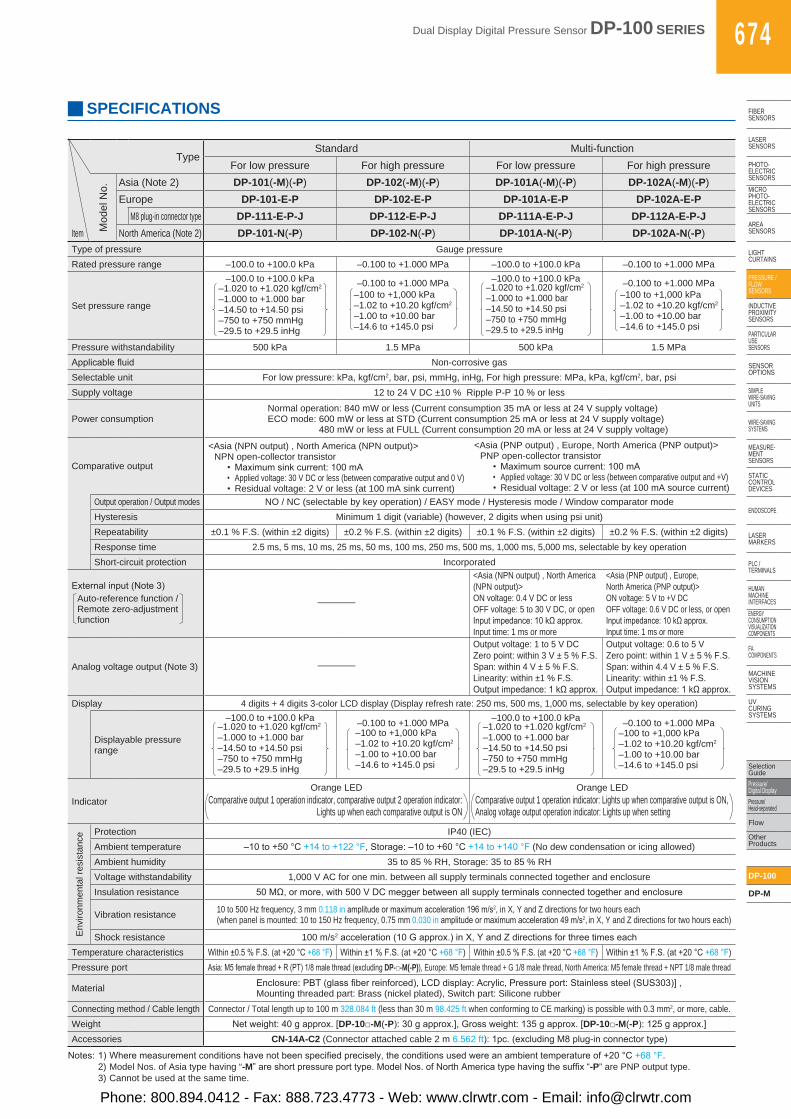
SPECIFICATIONS
Notes:1)Wheremeasurementconditionshavenotbeenspecifiedprecisely,theconditionsusedwereanambienttemperatureof+20°C+68°F.2) Model Nos. of Asia type having “-M”areshortpressureporttype.ModelNos.ofNorthAmericatypehavingthesuffix“-P” are PNP output type.3) Cannot be used at the same time.
TypeStandard Multi-function
For low pressure For high pressure For low pressure For high pressure
Mod
el N
o. Asia (Note 2) DP-101(-M)(-P) DP-102(-M)(-P) DP-101A(-M)(-P) DP-102A(-M)(-P)Europe DP-101-E-P DP-102-E-P DP-101A-E-P DP-102A-E-P
M8 plug-in connector type DP-111-E-P-J DP-112-E-P-J DP-111A-E-P-J DP-112A-E-P-JItem North America (Note 2) DP-101-N(-P) DP-102-N(-P) DP-101A-N(-P) DP-102A-N(-P)Type of pressure Gauge pressureRated pressure range –100.0 to +100.0 kPa –0.100 to +1.000 MPa –100.0 to +100.0 kPa –0.100 to +1.000 MPa
Set pressure range
–100.0 to +100.0 kPa–1.020 to +1.020 kgf/cm2
–1.000 to +1.000 bar–14.50 to +14.50 psi–750 to +750 mmHg–29.5 to +29.5 inHg
–0.100 to +1.000 MPa–100 to +1,000 kPa–1.02 to +10.20 kgf/cm2
–1.00 to +10.00 bar–14.6 to +145.0 psi
–100.0 to +100.0 kPa–1.020 to +1.020 kgf/cm2
–1.000 to +1.000 bar–14.50 to +14.50 psi–750 to +750 mmHg–29.5 to +29.5 inHg
–0.100 to +1.000 MPa–100 to +1,000 kPa–1.02 to +10.20 kgf/cm2
–1.00 to +10.00 bar–14.6 to +145.0 psi
Pressure withstandability 500 kPa 1.5 MPa 500 kPa 1.5 MPaApplicablefluid Non-corrosive gasSelectable unit For low pressure: kPa, kgf/cm2, bar, psi, mmHg, inHg, For high pressure: MPa, kPa, kgf/cm2, bar, psiSupply voltage 12 to 24 V DC ±10 % Ripple P-P 10 % or less
Power consumptionNormal operation: 840 mW or less (Current consumption 35 mA or less at 24 V supply voltage)ECO mode: 600 mW or less at STD (Current consumption 25 mA or less at 24 V supply voltage)
480 mW or less at FULL (Current consumption 20 mA or less at 24 V supply voltage)
Comparative output
<Asia (NPN output) , North America (NPN output)>NPN open-collector transistor
• Maximumsinkcurrent:100mA• Applied voltage: 30 V DC or less (between comparative output and 0 V)•Residual voltage: 2 V or less (at 100 mA sink current)
<Asia (PNP output) , Europe, North America (PNP output)>PNP open-collector transistor
• Maximumsourcecurrent:100mA• Applied voltage: 30 V DC or less (between comparative output and +V)•Residual voltage: 2 V or less (at 100 mA source current)
Output operation / Output modes NO / NC (selectable by key operation) / EASY mode / Hysteresis mode / Window comparator modeHysteresis Minimum 1 digit (variable) (however, 2 digits when using psi unit)Repeatability ±0.1 % F.S. (within ±2 digits) ±0.2 % F.S. (within ±2 digits) ±0.1 % F.S. (within ±2 digits) ±0.2 % F.S. (within ±2 digits)Response time 2.5 ms, 5 ms, 10 ms, 25 ms, 50 ms, 100 ms, 250 ms, 500 ms, 1,000 ms, 5,000 ms, selectable by key operationShort-circuit protection Incorporated
Externalinput(Note3)Auto-reference function /Remote zero-adjustment function
–
<Asia (NPN output) , North America (NPN output)>ON voltage: 0.4 V DC or lessOFF voltage: 5 to 30 V DC, or openInputimpedance:10kΩapprox.Input time: 1 ms or more
<Asia (PNP output) , Europe, North America (PNP output)>ON voltage: 5 V to +V DCOFF voltage: 0.6 V DC or less, or openInputimpedance:10kΩapprox.Input time: 1 ms or more
Analog voltage output (Note 3) –
Output voltage: 1 to 5 V DCZero point: within 3 V ± 5 % F.S.Span: within 4 V ± 5 % F.S.Linearity: within ±1 % F.S.Outputimpedance:1kΩapprox.
Output voltage: 0.6 to 5 VZero point: within 1 V ± 5 % F.S.Span: within 4.4 V ± 5 % F.S.Linearity: within ±1 % F.S.Outputimpedance:1kΩapprox.
Display 4 digits + 4 digits 3-color LCD display (Display refresh rate: 250 ms, 500 ms, 1,000 ms, selectable by key operation)
Displayable pressure range
–100.0 to +100.0 kPa–1.020 to +1.020 kgf/cm2
–1.000 to +1.000 bar–14.50 to +14.50 psi–750 to +750 mmHg–29.5 to +29.5 inHg
–0.100 to +1.000 MPa–100 to +1,000 kPa–1.02 to +10.20 kgf/cm2
–1.00 to +10.00 bar–14.6 to +145.0 psi
–100.0 to +100.0 kPa–1.020 to +1.020 kgf/cm2
–1.000 to +1.000 bar–14.50 to +14.50 psi–750 to +750 mmHg–29.5 to +29.5 inHg
–0.100 to +1.000 MPa–100 to +1,000 kPa–1.02 to +10.20 kgf/cm2
–1.00 to +10.00 bar–14.6 to +145.0 psi
IndicatorOrange LED
Comparative output 1 operation indicator, comparative output 2 operation indicator: Lights up when each comparative output is ON
Orange LEDComparative output 1 operation indicator: Lights up when comparative output is ON, Analog voltage output operation indicator: Lights up when setting
Env
ironm
enta
l res
ista
nce Protection IP40 (IEC)
Ambient temperature –10to+50°C+14to+122°F,Storage:–10to+60°C+14to+140°F (No dew condensation or icing allowed)Ambient humidity 35 to 85 % RH, Storage: 35 to 85 % RHVoltage withstandability 1,000 V AC for one min. between all supply terminals connected together and enclosureInsulation resistance 50MΩ,ormore,with500VDCmeggerbetweenallsupplyterminalsconnectedtogetherandenclosure
Vibration resistance 10 to 500 Hz frequency, 3 mm 0.118 inamplitudeormaximumacceleration196m/s2, in X, Y and Z directions for two hours each (when panel is mounted: 10 to 150 Hz frequency, 0.75 mm 0.030 inamplitudeormaximumacceleration49m/s2, in X, Y and Z directions for two hours each)
Shock resistance 100 m/s2acceleration(10Gapprox.)inX,YandZdirectionsforthreetimeseachTemperature characteristics Within±0.5%F.S.(at+20°C+68°F) Within±1%F.S.(at+20°C+68°F) Within±0.5%F.S.(at+20°C+68°F) Within±1%F.S.(at+20°C+68°F)Pressure port Asia:M5femalethread+R(PT)1/8malethread(excludingDP-□-M(-P)), Europe: M5 female thread + G 1/8 male thread, North America: M5 female thread + NPT 1/8 male thread
Material Enclosure:PBT(glassfiberreinforced),LCDdisplay:Acrylic,Pressureport:Stainlesssteel(SUS303)], Mounting threaded part: Brass (nickel plated), Switch part: Silicone rubber
Connecting method / Cable length Connector / Total length up to 100 m 328.084 ft (less than 30 m 98.425 ft when conforming to CE marking) is possible with 0.3 mm2, or more, cable.Weight Netweight:40gapprox.[DP-10□-M(-P):30gapprox.],Grossweight:135gapprox.[DP-10□-M(-P):125gapprox.]Accessories CN-14A-C2 (Connector attached cable 2 m 6.562 ft):1pc.(excludingM8plug-inconnectortype)
Phone: 800.894.0412 - Fax: 888.723.4773 - Web: www.clrwtr.com - Email: [email protected]
675 Dual Display Digital Pressure Sensor DP-100 SERIES
FIBERSENSORS
LASERSENSORS
PHOTO-ELECTRICSENSORS
MICROPHOTO-
ELECTRICSENSORS
AREASENSORS
LIGHTCURTAINS
PRESSURE / FLOW
SENSORS
INDUCTIVEPROXIMITY
SENSORS
PARTICULARUSE
SENSORS
SENSOROPTIONS
SIMPLEWIRE-SAVING
UNITS
WIRE-SAVING SYSTEMS
MEASURE-MENT
SENSORS
STATIC CONTROLDEVICES
ENDOSCOPE
LASERMARKERS
PLC /TERMINALS
HUMAN MACHINE
INTERFACESENERGY
CONSUMPTION VISUALIZATION COMPONENTS
FA COMPONENTS
MACHINE VISION
SYSTEMS
UV CURING
SYSTEMS
Selection Guide
Pressure/Digital Display
Pressure/Head-separated
Flow
Other Products
DP-100
DP-M
1kΩ
ZD1
D1
D2
Load
Tr1
Tr2
100mA max.
1
2
3
4
Users’ circuit Internal circuit
12 to 24 V DC±10 %
+
– (White) Analog voltage output
or External input
(Black) Comparative output 1
(Brown) +V
(Blue) 0 V
Terminal No. Color code of connector attached cable
Sen
sor c
ircui
t
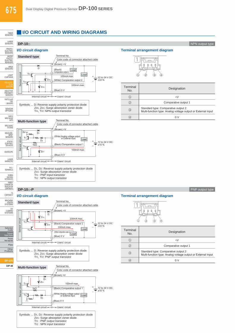
I/O CIRCUIT AND WIRING DIAGRAMS
I/O circuit diagram Terminal arrangement diagram
1 2 3 4
Terminal No. Designation
1 +V
2 Comparative output 1
3Standard type: Comparative output 2Multi-functiontype:AnalogvoltageoutputorExternalinput
4 0 V
Users’ circuit Internal circuit
D
12 to 24 V DC±10 %
+
–
Load
Load Tr1
ZD2
ZD1 Tr2
100mA max.
100mA max.
(Blue) 0 V
1
Terminal No. Color code of connector attached cable
2
3
4
(Black) Comparative output 1
(White) Comparative output 2
(Brown) +V
Sen
sor c
ircui
t
Standard type
Multi-function type
Symbols … D: Reverse supply polarity protection diodeZD1, ZD1: Surge absorption zener diodeTr1, Tr2: NPN output transistor
1kΩ
Users’ circuit Internal circuit
D1
D2 12 to 24 V DC±10 %
+
–
(White) Analog voltage output or External input Load
(Black) Comparative output 1
(Brown) +V
Tr1
5V
ZD1
Tr2
100mA max.
(Blue) 0 V
1
3
2
4
Terminal No. Color code of connector attached cable
Sen
sor c
ircui
t
Symbols … D1, D2: Reverse supply polarity protection diodeZD1: Surge absorption zener diodeTr1 : PNP input transistorTr2 : NPN output transistor
DP-10□ NPN output type
Users’ circuit Internal circuit
12 to 24 V DC±10 %
+
– (Black) Comparative output 1
Load
Load (White) Comparative output 2
(Brown) +V
Tr1 ZD2
ZD1
Tr2
100mA max.
100mA max.
(Blue) 0 V
D 1
2
3
4
Terminal No. Color code of connector attached cable
Sen
sor c
ircui
t
I/O circuit diagram Terminal arrangement diagram
1 2 3 4
Terminal No. Designation
1 +V
2 Comparative output 1
3 Standard type: Comparative output 2Multi-functiontype:AnalogvoltageoutputorExternalinput
4 0 V
Standard type
Multi-function type
Symbols … D: Reverse supply polarity protection diodeZD1, ZD1: Surge absorption zener diodeTr1, Tr2: PNP output transistor
Symbols … D1, D2: Reverse supply polarity protection diodeZD1: Surge absorption zener diodeTr1 : PNP output transistorTr2 : NPN input transistor
DP-10□-P PNP output type
Dual Display Digital Pressure Sensor DP-100 SERIES 676
FIBERSENSORS
LASERSENSORS
PHOTO-ELECTRICSENSORSMICROPHOTO-ELECTRICSENSORS
AREASENSORS
LIGHTCURTAINS
PRESSURE / FLOWSENSORS
INDUCTIVEPROXIMITYSENSORS
PARTICULARUSE SENSORS
SENSOROPTIONS
SIMPLEWIRE-SAVINGUNITS
WIRE-SAVING SYSTEMS
MEASURE-MENTSENSORS
STATIC CONTROLDEVICES
ENDOSCOPE
LASERMARKERS
PLC /TERMINALS
HUMAN MACHINE INTERFACESENERGY CONSUMPTION VISUALIZATION COMPONENTS
FA COMPONENTS
MACHINE VISION SYSTEMS
UV CURING SYSTEMS
Selection GuidePressure/Digital DisplayPressure/Head-separated
Flow
Other Products
DP-100
DP-M
ZD1
D1
D2
(White) Analog voltage output or External input
Load
(Black) Comparative output 1
Tr1
Tr2
100 mA max.
1
4
2
3
Users’ circuit Internal circuit
12 to 24 V DC±10 %
+
–
(Brown) +V
(Blue) 0 V
Sen
sor c
ircui
t
Terminal No. Color code of connection cable
1kΩ
12 to 24 V DC±10 %
+
– (Black) Comparative output 1
Load
Load (White) Comparative output 2
Tr1 ZD2
ZD1
Tr2
100 mA max.
100 mA max.
(Blue) 0 V
D 1
4
2
3
Users’ circuit Internal circuit
Sen
sor c
ircui
t
Terminal No. Color code of connection cable
(Brown) +V
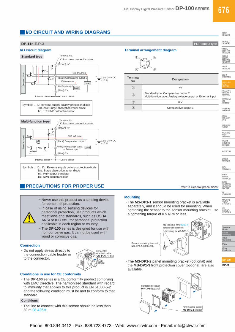
I/O circuit diagram Terminal arrangement diagram
Terminal No. Designation
1 +V
2 Standard type: Comparative output 2Multi-functiontype:AnalogvoltageoutputorExternalinput
3 0 V
4 Comparative output 1
Standard type
Multi-function type
Symbols … D: Reverse supply polarity protection diodeZD1, ZD1: Surge absorption zener diodeTr1, Tr2: PNP output transistor
Mounting•The MS-DP1-1 sensor mounting bracket is available
separately, and it should be used for mounting. When tightening the sensor to the sensor mounting bracket, use a tightening torque of 0.5 N·m or less.
Sensor mounting bracketMS-DP1-1 (Optional)
M3 (length 6 mm 0.236 in)screws with washers
(Accessory for MS-DP1-1)
•The MS-DP1-2 panel mounting bracket (optional) and the MS-DP1-3 front protection cover (optional) are also available.
Front protection coverMS-DP1-3(optional)
Panel mounting bracketMS-DP1-2(optional)
ConnectionConnectorattached cable[CN-14A(-R)-C□]
•Do not apply stress directly to the connection cable leader or to the connector.
Conditions in use for CE conformity•The DP-100 series is a CE conformity product complying
with EMC Directive. The harmonized standard with regard to immunity that applies to this product is EN 61000-6-2 and the following condition must be met to conform to that standard.
Conditions
•The line to connect with this sensor should be less than 30 m 98.425 ft.
PRECAUTIONS FOR PROPER USE Refer to General precautions.
I/O CIRCUIT AND WIRING DIAGRAMS
1 2
3 4
Symbols … D1, D2: Reverse supply polarity protection diodeZD1: Surge absorption zener diodeTr1: PNP output transistorTr2: NPN input transistor
DP-11□-E-P-J PNP output type
•Never use this product as a sensing device for personnel protection.
•In case of using sensing devices for personnel protection, use products which meet laws and standards, such as OSHA, ANSI or IEC etc., for personnel protection applicable in each region or country.
•The DP-100 series is designed for use with non-corrosive gas. It cannot be used with liquid or corrosive gas.
Phone: 800.894.0412 - Fax: 888.723.4773 - Web: www.clrwtr.com - Email: [email protected]
677 Dual Display Digital Pressure Sensor DP-100 SERIES
FIBERSENSORS
LASERSENSORS
PHOTO-ELECTRICSENSORS
MICROPHOTO-
ELECTRICSENSORS
AREASENSORS
LIGHTCURTAINS
PRESSURE / FLOW
SENSORS
INDUCTIVEPROXIMITY
SENSORS
PARTICULARUSE
SENSORS
SENSOROPTIONS
SIMPLEWIRE-SAVING
UNITS
WIRE-SAVING SYSTEMS
MEASURE-MENT
SENSORS
STATIC CONTROLDEVICES
ENDOSCOPE
LASERMARKERS
PLC /TERMINALS
HUMAN MACHINE
INTERFACESENERGY
CONSUMPTION VISUALIZATION COMPONENTS
FA COMPONENTS
MACHINE VISION
SYSTEMS
UV CURING
SYSTEMS
Selection Guide
Pressure/Digital Display
Pressure/Head-separated
Flow
Other Products
DP-100
DP-M
PRECAUTIONS FOR PROPER USE Refer to General precautions.
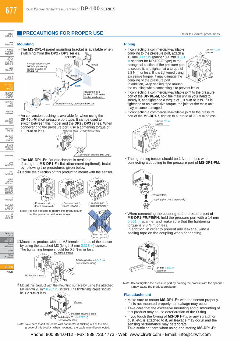
•The MS-DP1-4 panel mounting bracket is available when switching from the DP2 / DP3 series.
•If connecting a commercially-available coupling to the pressure port, attach a 12 mm 0.472 in spanner (14 mm 0.551 in spanner for DP-100-E type) to the hexagonalsectionofthepressureportto secure it, and tighten at a torque of 9.8 N·m or less. If it is tightened using excessivetorque,itmaydamagethecoupling or the pressure port. In addition, wrap sealing tape around the coupling when connecting it to prevent leaks.
•If connecting a commercially-available joint to the pressure port of the DP-10□-M, hold the main unit in your hand to steady it, and tighten to a torque of 1.0 N·m or less. If it is tightenedtoanexcessivetorque,thejointorthemainunitmay become damaged.
•If connecting a commercially-available joint to the pressure port of the MS-DP1-7, tighten to a torque of 9.8 N·m or less.
•Make sure to mount MS-DP1-F□ with the sensor properly. If it is not mounted properly, air leakage may occur.
•Takecarethattheexcessivemountinganddismountingofthis product may cause deterioration of the O-ring.
•If you touch the O-ring of MS-DP1-F□, or any scratch or dust, etc. is attached to it, air leakage may occur and the sensing performance may deteriorate. TakesufficientcarewhenusingandstoringMS-DP1-F□.
•The tightening torque should be 1 N·m or less when connecting a coupling to the pressure port of MS-DP1-FM.
•When connecting the coupling to the pressure port of MS-DP1-FR/FE/FN, hold the pressure port with a 14 mm 0.551 in spanner and make sure that the tightening torque is 9.8 N·m or less. In addition, in order to prevent any leakage, wind a sealing tape on the coupling when connecting.
•An conversion bushing is available for when using the DP-10□-M short pressure port type. It can be used to switch between this model and the DP2 / DP3 series. When connecting to the pressure port, use a tightening torque of 1.0 N·m or less.
•The MS-DP1-F□flatattachmentisavailable. If using the MS-DP1-F□flatattachment(optional),installby following the procedures given below.
1 Decide the direction of this product to mount with the sensor.
2 Mount this product with the M3 female threads of the sensor by using the attached M3 (length 8 mm 0.315 in) screws. The tightening torque should be 0.5 N·m or less.
3 Mount this product with the mounting surface by using the attached M4 (length 20 mm 0.787 in) screws. The tightening torque should be 1.2 N·m or less.
Mounting Piping
Flat attachment
DP2-20
ñ101.3kPa
OUT2
OUT1
MODE
0-ADJ
Front protective coverDPX-04 (Optional) can be installed on MS-DP1-4.
DP2 / DP3
DP-100
Insert
Remove
Remove
Panel mounting bracket MS-DP1-4
Mounting holesfor DP2 / DP3 seriescan be used as is.
Conversion bushing MS-DP1-7
M5 female thread Rc1/8 female thread
Note: It is not possible to mount this product such that the pressure port faces upward.
Pressure port faces downward
Pressure port faces leftward
Pressure port faces rightward
Pressure port faces upward
M3 (length 8 mm 0.315 in)screw (Accessory)
M3 female thread
M3 female thread
Connector attached cable
Groove
M4 (length 20 mm 0.787 in)screw (Accessory)
Note: Take care that if the cable with connector is sticking out of the side groove of this product when mounting, the cable may disconnected.
Connector attached cable
Groove
M4 (length 20 mm 0.787 in)screw (Accessory)
Note: Take care that if the cable with connector is sticking out of the side groove of this product when mounting, the cable may disconnected.
12 mm 0.472 in spanner
14 mm 0.551 in spanner
Coupling (Purchase separately.)
Pressure port
14 mm 0.551 inspanner
Note: Do not tighten the pressure port by holding the product with the spanner. It may cause the product breakage.
Phone: 800.894.0412 - Fax: 888.723.4773 - Web: www.clrwtr.com - Email: [email protected]
Dual Display Digital Pressure Sensor DP-100 SERIES 678
FIBERSENSORS
LASERSENSORS
PHOTO-ELECTRICSENSORSMICROPHOTO-ELECTRICSENSORS
AREASENSORS
LIGHTCURTAINS
PRESSURE / FLOWSENSORS
INDUCTIVEPROXIMITYSENSORS
PARTICULARUSE SENSORS
SENSOROPTIONS
SIMPLEWIRE-SAVINGUNITS
WIRE-SAVING SYSTEMS
MEASURE-MENTSENSORS
STATIC CONTROLDEVICES
ENDOSCOPE
LASERMARKERS
PLC /TERMINALS
HUMAN MACHINE INTERFACESENERGY CONSUMPTION VISUALIZATION COMPONENTS
FA COMPONENTS
MACHINE VISION SYSTEMS
UV CURING SYSTEMS
Selection GuidePressure/Digital DisplayPressure/Head-separated
Flow
Other Products
DP-100
DP-M
PRECAUTIONS FOR PROPER USE Refer to General precautions.
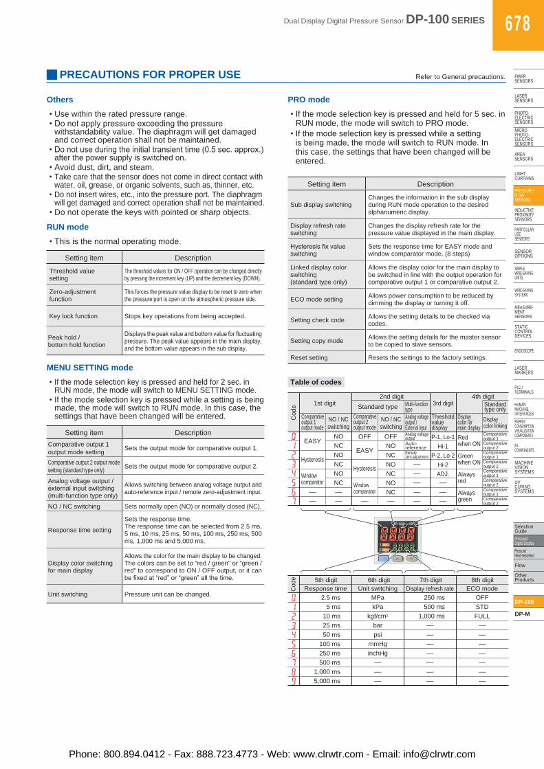
PRO mode
•If the mode selection key is pressed and held for 5 sec. in RUN mode, the mode will switch to PRO mode.
•If the mode selection key is pressed while a setting is being made, the mode will switch to RUN mode. In this case, the settings that have been changed will be entered.
Setting item Description
Sub display switchingChanges the information in the sub display during RUN mode operation to the desired alphanumeric display.
Display refresh rateswitching
Changes the display refresh rate for the pressure value displayed in the main display.
Hysteresisfixvalueswitching
Sets the response time for EASY mode and window comparator mode. (8 steps)
Linked display colorswitching(standard type only)
Allows the display color for the main display to be switched in line with the output operation for comparative output 1 or comparative output 2.
ECO mode setting Allows power consumption to be reduced by dimming the display or turning it off.
Setting check code Allows the setting details to be checked via codes.
Setting copy mode Allows the setting details for the master sensor to be copied to slave sensors.
Reset setting Resets the settings to the factory settings.
– – – – – – – – – –
– – ADJ. –
–
Analog voltage output Auto- reference Remote zero-adjustment
Comparative output 1 Comparative output 2
NO OFF OFF Comparative output 1 P-1, Lo-1
NC NO Comparative output 2 Hi-1
NO NC Comparative output 1 P-2, Lo-2
NC NO Comparative output 2 Hi-2
NO NC
NC
Comparative output 1
NC NO Comparative output 2
EASY
Cod
e
Hysteresis
Window comparator
EASY
Hysteresis
Window comparator
Red when ON
Green when ON
Always red
Always green
1st digit
Analog voltage output / External input
NO / NC switching
Comparative output 2 output mode
Comparative output 1 output mode
NO / NC switching
Display color for main display
Threshold value display
Display color linking
Standard type only
2nd digit Standard type Multi-function
type 3rd digit
4th digit
2.5 ms MPa 250 ms OFF 5 ms kPa 500 ms STD
10 ms kgf/cm2 1,000 ms FULL 25 ms bar – – 50 ms psi – –
100 ms mmHg – – 250 ms inchHg – – 500 ms – – –
1,000 ms – – – 5,000 ms – – –
Response time Unit switching Display refresh rate ECO mode 5th digit 6th digit 7th digit 8th digit
Cod
e
Others
•Use within the rated pressure range.•Donotapplypressureexceedingthepressure
withstandability value. The diaphragm will get damaged and correct operation shall not be maintained.
•Donotuseduringtheinitialtransienttime(0.5sec.approx.)after the power supply is switched on.
•Avoid dust, dirt, and steam.•Take care that the sensor does not come in direct contact with
water, oil, grease, or organic solvents, such as, thinner, etc.•Do not insert wires, etc., into the pressure port. The diaphragm
will get damaged and correct operation shall not be maintained.•Do not operate the keys with pointed or sharp objects.
MENU SETTING mode
•If the mode selection key is pressed and held for 2 sec. in RUN mode, the mode will switch to MENU SETTING mode.
•If the mode selection key is pressed while a setting is being made, the mode will switch to RUN mode. In this case, the settings that have been changed will be entered.
Setting item DescriptionComparative output 1output mode setting Sets the output mode for comparative output 1.
Comparative output 2 output modesetting (standard type only) Sets the output mode for comparative output 2.
Analog voltage output /externalinputswitching(multi-function type only)
Allows switching between analog voltage output and auto-reference input / remote zero-adjustment input.
NO / NC switching Sets normally open (NO) or normally closed (NC).
Response time setting
Sets the response time.The response time can be selected from 2.5 ms, 5 ms, 10 ms, 25 ms, 50 ms, 100 ms, 250 ms, 500 ms, 1,000 ms and 5,000 ms.
Display color switchingfor main display
Allows the color for the main display to be changed.The colors can be set to “red / green” or “green / red” to correspond to ON / OFF output, or it can befixedat“red”or“green”allthetime.
Unit switching Pressure unit can be changed.
RUN mode
•This is the normal operating mode.
Setting item Description
Threshold valuesetting
The threshold values for ON / OFF operation can be changed directly by pressing the increment key (UP) and the decrement key (DOWN).
Zero-adjustmentfunction
This forces the pressure value display to be reset to zero when the pressure port is open on the atmospheric pressure side.
Key lock function Stops key operations from being accepted.
Peak hold /bottom hold function
Displaysthepeakvalueandbottomvalueforfluctuatingpressure. The peak value appears in the main display, and the bottom value appears in the sub display.
Table of codes
Phone: 800.894.0412 - Fax: 888.723.4773 - Web: www.clrwtr.com - Email: [email protected]
679 Dual Display Digital Pressure Sensor DP-100 SERIES
FIBERSENSORS
LASERSENSORS
PHOTO-ELECTRICSENSORS
MICROPHOTO-
ELECTRICSENSORS
AREASENSORS
LIGHTCURTAINS
PRESSURE / FLOW
SENSORS
INDUCTIVEPROXIMITY
SENSORS
PARTICULARUSE
SENSORS
SENSOROPTIONS
SIMPLEWIRE-SAVING
UNITS
WIRE-SAVING SYSTEMS
MEASURE-MENT
SENSORS
STATIC CONTROLDEVICES
ENDOSCOPE
LASERMARKERS
PLC /TERMINALS
HUMAN MACHINE
INTERFACESENERGY
CONSUMPTION VISUALIZATION COMPONENTS
FA COMPONENTS
MACHINE VISION
SYSTEMS
UV CURING
SYSTEMS
Selection Guide
Pressure/Digital Display
Pressure/Head-separated
Flow
Other Products
DP-100
DP-M
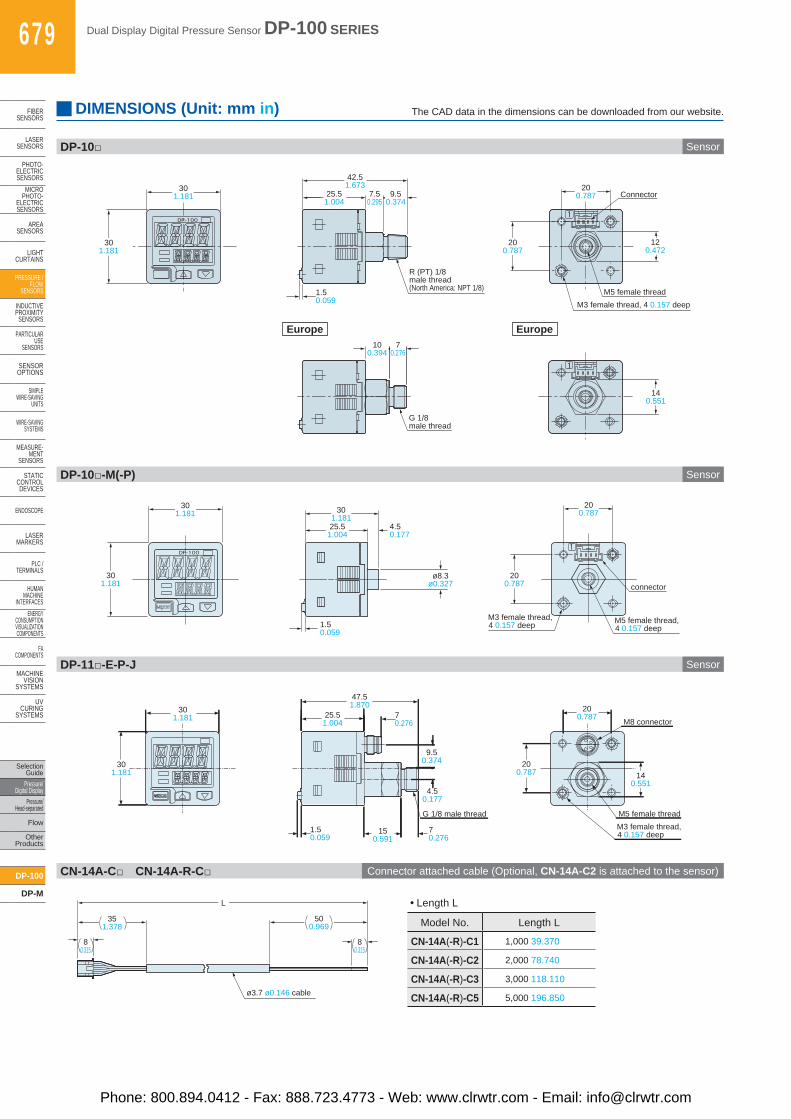
DIMENSIONS (Unit: mm in) The CAD data in the dimensions can be downloaded from our website.
DP-10□ Sensor
20 0.787
20 0.787
M3 female thread, 4 0.157 deep M5 female thread
12 0.472
Connector
1.5 0.059
30 1.181
30 1.181 9.5
0.374
42.5 1.673
7.5 0.295
R (PT) 1/8 male thread (North America: NPT 1/8)
25.5 1.004
Europe
G 1/8 male thread
10 0.394
7 0.276
14 0.551
Europe
DP-10□-M(-P) Sensor
30 1.181
30 1.181
20 0.787
1.5 0.059
4.5 0.177
ø8.3 ø0.327
30 1.181
20 0.787
25.5 1.004
M5 female thread, 4 0.157 deep
M3 female thread, 4 0.157 deep
connector
DP-11□-E-P-J Sensor
301.181
301.181
47.51.870
70.276
25.51.004
150.591
70.276
1.50.059
G 1/8 male thread
9.50.374
4.50.177
M3 female thread,4 0.157 deep
M5 female thread
M8 connector
200.787
200.787
140.551
CN-14A-C□ CN-14A-R-C□ Connector attached cable (Optional, CN-14A-C2 is attached to the sensor)
351.378
80.315
500.969
L
ø3.7 ø0.146 cable
80.315
Model No. Length L
CN-14A(-R)-C1 1,000 39.370
CN-14A(-R)-C2 2,000 78.740
CN-14A(-R)-C3 3,000 118.110
CN-14A(-R)-C5 5,000 196.850
• Length L
Phone: 800.894.0412 - Fax: 888.723.4773 - Web: www.clrwtr.com - Email: [email protected]

Dual Display Digital Pressure Sensor DP-100 SERIES 680
FIBERSENSORS
LASERSENSORS
PHOTO-ELECTRICSENSORSMICROPHOTO-ELECTRICSENSORS
AREASENSORS
LIGHTCURTAINS
PRESSURE / FLOWSENSORS
INDUCTIVEPROXIMITYSENSORS
PARTICULARUSE SENSORS
SENSOROPTIONS
SIMPLEWIRE-SAVINGUNITS
WIRE-SAVING SYSTEMS
MEASURE-MENTSENSORS
STATIC CONTROLDEVICES
ENDOSCOPE
LASERMARKERS
PLC /TERMINALS
HUMAN MACHINE INTERFACESENERGY CONSUMPTION VISUALIZATION COMPONENTS
FA COMPONENTS
MACHINE VISION SYSTEMS
UV CURING SYSTEMS
Selection GuidePressure/Digital DisplayPressure/Head-separated
Flow
Other Products
DP-100
DP-M
DIMENSIONS (Unit: mm in) The CAD data in the dimensions can be downloaded from our website.
MS-DP1-1 Sensor mounting bracket (Optional)
MS-DP1-5 Sensor mounting bracket (Optional)
MS-DP1-2 MS-DP1-3 Panel mounting bracket (Optional), Front protection cover (Optional)
Assembly dimensions
Assembly dimensions
Assembly dimensions
Material: Cold rolled carbon steel (SPCC) (Uni-chrome plated)Two M3 (length 6 mm 0.236 in) screws with washers are attached.
Material: Cold rolled carbon steel (SPCC) (Uni-chrome plated)Two M3 (length 6 mm 0.236 in) screws with washers are attached.
Note: The panel thickness should be 1 to 6 mm 0.039 to 0.236 in.
Note: The panel thickness should be 1 to 6 mm 0.039 to 0.236 in.
Material: POM (Panel mounting bracket) Polycarbonate (Front protection cover)
Mounting drawing with DP-10□
Mounting drawing with DP-10□-M
Mounting drawing with DP-10□ When 1 unit is installed
When “n” units are installed horizontally in series When “n” units are installed vertically in series
4.20.165
9.50.37414.5
0.571
2-R2.1 R0.083
ø2.3ø0.091
10.039
220.866
t 2t 0.079 20
0.787
5.50.217
441.732
R13R0.512
130.512
200.787
301.181
200.787
2-ø3.5 ø0.138
5.30.209( )
4.20.165
9.50.374
2-R2.1 R0.083220.866
14.50.571
25.51.004
150.591
301.181
301.181 45
1.772
451.772
7.50.295
1.50.059
9.50.374
t 2t 0.079
301.181
42.51.673
120.472
22.750.896
200.787
29.51.161
200.787
13.50.531
4.50.177
44.51.75230
1.181
281.102
t 1.5t 0.059
8.50.335
ø4.5ø0.177
2-ø3.5 ø0.138
200.787
( )200.787
4.50.177
28.51.122
49.51.949
ø4.5ø0.177
49.51.949
301.181
29.51.161
53.52.106
1.50.059
4.50.177
301.181
R6.75R0.266
160.630
ø8.3ø0.327
t 1.5t0.059
281.102
200.787
34.51.358
200.787
34.51.358
39.31.547
( )
( )
8.70.343
7.20.283
110.433
9.50.374
7.50.295
Panel thickness dimension 1 to 6 mm 0.039 to 0.236 in
18.30.720
33.41.315
501.96933.41.315
M3 female thread,4 0.157 deep
Connector
Front protection cover
M5 female thread,4 0.157 deep
(52 2.047 max)
120.472
R(PT) 1/8male thread
View A
31 0−0.4
31 0−0.4
1.220 0−0.016
1.220 0−0.016
31 1.220 × n + 3.5 0.138 × (n-1)
55 2.165or more
31 1.220 × n + 3.5 0.138 × (n-1)
55 2.165or more
31 0−0.4
31 0−0.4
1.220 0−0.016
1.220 0−0.016
Panel cut-out dimensions
Phone: 800.894.0412 - Fax: 888.723.4773 - Web: www.clrwtr.com - Email: [email protected]
681 Dual Display Digital Pressure Sensor DP-100 SERIES
FIBERSENSORS
LASERSENSORS
PHOTO-ELECTRICSENSORS
MICROPHOTO-
ELECTRICSENSORS
AREASENSORS
LIGHTCURTAINS
PRESSURE / FLOW
SENSORS
INDUCTIVEPROXIMITY
SENSORS
PARTICULARUSE
SENSORS
SENSOROPTIONS
SIMPLEWIRE-SAVING
UNITS
WIRE-SAVING SYSTEMS
MEASURE-MENT
SENSORS
STATIC CONTROLDEVICES
ENDOSCOPE
LASERMARKERS
PLC /TERMINALS
HUMAN MACHINE
INTERFACESENERGY
CONSUMPTION VISUALIZATION COMPONENTS
FA COMPONENTS
MACHINE VISION
SYSTEMS
UV CURING
SYSTEMS
Selection Guide
Pressure/Digital Display
Pressure/Head-separated
Flow
Other Products
DP-100
DP-M
Spacer
Connector
M5 femalethread
120.472
562.205
803.150
361.417
+0.50+0.0200
361.417
+0.50
+0.0200
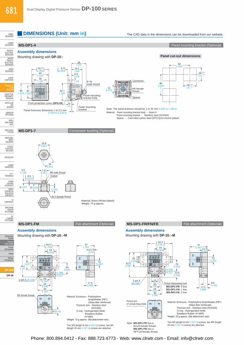
Note: The panel tickness should be 1 to 32 mm 0.039 to 1.260 in.Material: Panel mounting bracket body ··· Nylon 6 Panel mounting bracket ··· Stainless steel (SUS304) Spacer ··· Cold rolled carbon steel (SPCC)(Uni-chrome plated)
Material: Brass (Nickel plated)Weight:10gapprox.
Note: MS-DP1-FR has a Rc1/8 female thread. MS-DP1-FN has a NPT1/8 female thread.
301.181
301.181
401.575
42.71.681( )
30.118
361.417
6.50.256
26.51.043
9.70.382( )
42.71.681
Panel thickness dimension 1 to 3.2 mm0.039 to 0.126 in
8 0.315
Front protection cover (DPX-04)
Panel mountingbracket body
Panel mountingbracket
R 1/8male thread
401.575
3.50.138
7.80.307
80.315
11 0.433 10 0.394
140.551
M5 male threadGasket
Rc1/8 female thread
0.50.020( )
15.80.622
DIMENSIONS (Unit: mm in) The CAD data in the dimensions can be downloaded from our website.
MS-DP1-4 Panel mounting bracket (Optional)
MS-DP1-7 Conversion bushing (Optional)
MS-DP1-FM Flat attachment (Optional) MS-DP1-FR/FN/FE Flat attachment (Optional)
Assembly dimensionsMounting drawing with DP-10□ Panel cut-out dimensions
Assembly dimensions Assembly dimensionsMounting drawing with DP-10□-M Mounting drawing with DP-10□-M
M5 female thread
8.5 0.335
200.787
5.5 0.217 6.5 0.256
44.51.752
240.945
44.51.752
2-ø4.3 ø0.169
11.50.453
371.457
17.50.689
110.433
301.181
240.945
240.945
301.181
( )( )
Material: Enclosure···Polybutylene terephthalate (PBT) (Glassfiberreinforced) Pressure port··· Stainless steel
(SUS303) O-ring···Hydrogenated Nitrile Butadiene Rubber (H-NBR)Weight:15gapprox.(flatattachmentonly)
Two M3 (length 8 mm 0.315 in) screws, two M4 (length 20 mm 0.787 in) screws are attached.
5.5 0.217 6.5 0.256
371.457
110.433
8.50.335
17.50.689
11.50.453
Pressure portG1/8 female thread (Note)
200.787
140.551
13.50.531
Product distinguishing markMS-DP1-FR: 0 lineMS-DP1-FN: 1 lineMS-DP1-FE: 2 line
52.52.067( )
240.945( )
301.181
240.945
2-ø4.3ø0.169
52.52.067
301.181
240.945
Material: Enclosure···Polybutylene terephthalate (PBT) (Glassfiberreinforced) Pressure port···Stainless steel (SUS303) O-ring···Hydrogenated Nitrile Butadiene Rubber (H-NBR)Weight:25gapprox.(flatattachmentonly)
Two M3 (length 8 mm 0.315 in) screws, two M4 (length 20 mm 0.787 in) screws are attached.
Phone: 800.894.0412 - Fax: 888.723.4773 - Web: www.clrwtr.com - Email: [email protected]