Embed Size (px)
Citation preview
Panel Erection Information
Pane
l Ere
ctio
n In
form
atio
n
As the tilt-up panel is rotated from the horizontal to the vertical, the panel is subjected to bending that causes both compressive and tensile stresses that must be resisted by the concrete, reinforcing steel, or a method of strongbacking that prevents the initial bending.
The lifting inserts are normally located so that the over-hanging portions of the panel sides or top will reduce the bending moments between pickup points, thereby reducing the compressive and tensile stresses in the concrete.
Tilt-up panels are usually thin and very seldom do they contain two layers of reinforcing steel. It is, therefore, neces-sary to allow some tensile stress in the concrete to be intro-duced in the tension areas. The value of allowable tensile stress in the concrete is a function of the modulus of rupture and the safety factor used. A conservative value appears to be approximately
Since the typical reinforcing in a panel is #4 bars at 12 in. o.c., both horizontally and vertically, it is important to be sure of the compressive strength of the concrete at the time of erection. In turn, the concrete must have sufficient tensile strength to provide the resisting strength necessary to erect the panels without cracking. This concrete quality can be obtained by having a proper mix proportion and a curing process that minimizes moisture loss. Strength tests using compression cylinders, Test Beam Break (modulus of rupture), or a Split Cylinder Test are methods of determining the value of the concrete strength and/or tensile strength of the concrete at the time of erection.
It is normal to have a minimum concrete compressive strength of 2,500 psi before the tilting operation commences. Generally, the ultimate tensile stress would be 375 psi or greater with an allowable stress of 300 psi. This assures a good tilting sequence with no cracking from tilting although some shrinkage cracks may appear.
The engineering service (Erection Details) which is pro-vided by Dayton Superior is a very important part of our total tilt-up package. The location and selection of the proper lifting insert, brace type and brace anchor location, as well as the calculation of additional reinforcing steel or strongback size and location is critical for a safe and efficient panel erec-tion.
Dayton Superior uses computers to provide fast and accurate analysis of the stresses involved in tilting a panel into position. Erection detail booklets are furnished to the contractor showing pickup locations, wall brace insert loca-tions, crane riggings and cable lengths, reinforcing or strong-back details, and specific assumptions relating to concrete strength and wind loads used in the brace design. These details are furnished at a nominal charge and are as impor-tant to the success of the operation as are the contract draw-ings. In order to provide these erection details to the tilt-up contractor, Dayton Superior needs the following information:
• Name of our dealer where you will purchase accessories.
• Name and address of project.
• Name of contractor.
• Job phone number.
• Name of job superintendent.
• Crane operator.
• Project plans with panel drawings.
• Number of buildings.
• Approximate number of panels.
• Number of detail booklets required.
• Date erection details required.
• Are copies of calculations required?
• Is engineer’s stamp required?
• Type of inserts preferred for tilting, bracing and strongbacking.
• Rigging type preferred for tilting.
• Are braces required? If so, what is the specified maximum wind load (psf)? Are panels to be braced to inside or outside of the building?
• Are panels cast inside face up or outside face up?
• Type and unit weight of concrete.
• Compressive strength of concrete at lift.
• Type and details of surface treatment.
• Special instructions not covered by the above items.
√6 f’c.
1502-09
Depending upon the quality of bond breaker used and the care taken in application, the amount of “bond” between the panel and the base slab can be from negligible to signifi-cant. Initially, a suction force must be overcome at the time of release from the base slab and estimates of this force vary considerably. Panel size, interface texture, and water between the panel face and the base slab all contribute to this additional load that is applied to the inserts and the sur-rounding concrete. Estimates vary from negligible to 20 psf of panel area. Experience has shown that the safety factor between the design stress and the ultimate tensile stress is sufficient to absorb the additional stresses without cracking the panels.
Minor impact loads that occur during the tilting sequence do not create bending stresses in excess of the safety factor. However, if a panel suddenly drops and is caught by the slings, or hits the crane boom or some other obstruction, an increased load will be applied to the pickup inserts.
Panels are analyzed for stresses at 0 degrees and at various angles during the tilting sequence. They are ana-lyzed at 0 degrees because of the added loads from suc- tion, impact, bond, and because the spans are the longest. Panels with more than one horizontal row of pickup points are analyzed at angles of rotation due to the cable configura-tion changing the loads to the pickup points and therefore, changing the bending moments. The resultant stresses are compared to the allowable and if exceeded, additional rein-forcing or strongbacks are added depending upon the con-tractor’s preference.
After the tilt-up panels are analyzed vertically, they are examined horizontally. The procedure for horizontal analysis is similar to the vertical examination, except that a portion of the panel resting on the ground is not considered because of continuous support.
Panel Analysis
Erection Details

Panel Erection Information
Pane
l Ere
ctio
n In
form
atio
n
30o
20o
50o
• All panels with openings are entered in the computer for analysis.
• Inserts are then positioned relative to the center of gravity.
• Panel dimensions and insert locations are checked by the computer for exact insert loading and flexural stress analysis.
• The bending moments and stresses in a panel are constantly changing as the panel rotates from 0° (hori-zontal) to approximately 90° (vertical).
• Stresses are checked at various degrees of rotation with respect to the horizontal.
• The most critical stress during lifting will normally occur somewhere between 20° and 50° rotation. The reason for this range is the different geometric shapes of the panels and number of inserts required.
• The calculations for determining the stresses at varying angles of rotation are extremely complex due to the cable geometry and the method of structural analysis required, and can only be accomplished efficiently by utilizing the accuracy and speed of the computer.
• As the cable, attached to the lifting plate, changes its angle during rotation, the force components on the lifting plate will vary causing the tension load on the insert to vary.
• When one insert's tension load increases, another insert's tension load may decrease. This is what causes the bending moments and stresses to vary throughout rotation of the panel.
• For example: the tension load at "B" in Fig. 3 is 100% tension and the tension load at "C" is 85% tension, but when rotated to 30° in Fig. 4, the tension load at "B" has decreased to 80% and the tension load at "C" has increased to 100%.
• To provide uniformity in panel detailing, Dayton Superior provides computerized or computer aided drafting graphics in addition to the stress analysis.
Fig. 1
Fig. 2
Fig. 3
Fig.4
A
B
C
A B C
ANGLE @ 0o ROTATION
A ≈ 60o
B ≈ 90o
C ≈ 60o
ANGLE @ 30o ROTATION
A ≈ 30o
B ≈ 60o
C ≈ 90o
Computer Service
16 02-09
Panel Erection Information
Pane
l Ere
ctio
n In
form
atio
n
Stress Tables and Rigging Patterns
f'c 2,000
268 287 300 311 328 354 379
2,300 2,500 2,700 3,000 3,500 4,000
AllowableBendingStress
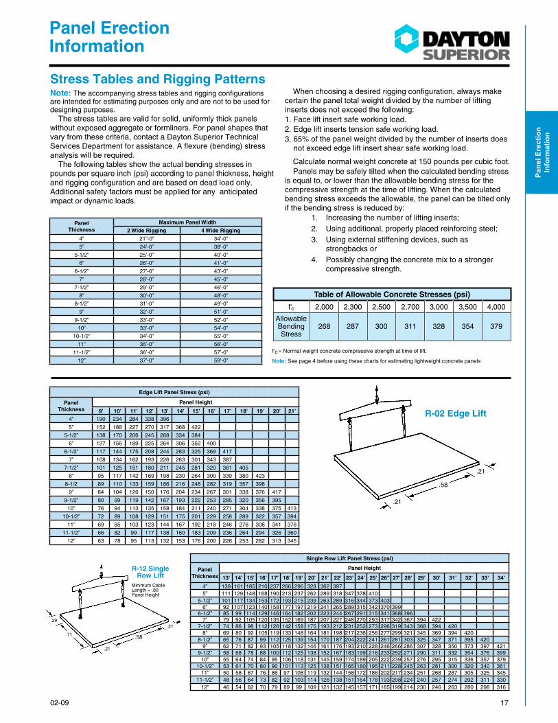
Table of Allowable Concrete Stresses (psi)
f’c = Normal weight concrete compressive strength at time of lift.
Note: See page 4 before using these charts for estimating lightweight concrete panels
R-02 Edge Lift
.58
.21
.21
.58
Minimum CableLength = .80 Panel Height
.21
.29
.71
R-12 Single Row Lift
.21
Panel Thickness
Maximum Panel Width
2 Wide Rigging 4 Wide Rigging
4” 21”-0” 34’-0”
5” 24’-0” 38’-0”
5-1/2” 25’-0” 40’-0”
6” 26’-0” 41’-0”
6-1/2” 27’-0” 43’-0”
7” 28’-0” 45’-0”
7-1/2” 29’-0” 46’-0”
8” 30’-0” 48’-0”
8-1/2” 31’-0” 49’-0”
9” 32’-0” 51’-0”
9-1/2” 33’-0” 52’-0”
10” 33’-0” 54’-0”
10-1/2” 34’-0” 55’-0”
11” 35’-0” 56’-0”
11-1/2” 36’-0” 57’-0”
12” 37’-0” 59’-0”
Note: The accompanying stress tables and rigging configurations are intended for estimating purposes only and are not to be used for designing purposes.
The stress tables are valid for solid, uniformly thick panels without exposed aggregate or formliners. For panel shapes that vary from these criteria, contact a Dayton Superior Technical Services Department for assistance. A flexure (bending) stress analysis will be required.
The following tables show the actual bending stresses in pounds per square inch (psi) according to panel thickness, height and rigging configuration and are based on dead load only. Additional safety factors must be applied for any anticipated impact or dynamic loads.
When choosing a desired rigging configuration, always make certain the panel total weight divided by the number of lifting inserts does not exceed the following:1. Face lift insert safe working load.2. Edge lift inserts tension safe working load.3. 65% of the panel weight divided by the number of inserts does
not exceed edge lift insert shear safe working load.
Calculate normal weight concrete at 150 pounds per cubic foot.Panels may be safely tilted when the calculated bending stress
is equal to, or lower than the allowable bending stress for the compressive strength at the time of lifting. When the calculated bending stress exceeds the allowable, the panel can be tilted only if the bending stress is reduced by: 1. Increasing the number of lifting inserts; 2. Using additional, properly placed reinforcing steel; 3. Using external stiffening devices, such as
strongbacks or 4. Possibly changing the concrete mix to a stronger compressive strength.
Edge Lift Panel Stress (psi)
Panel Thickness
Panel Height
9’ 10’ 11’ 12’ 13’ 14’ 15’ 16’ 17’ 18’ 19’ 20’ 21’4” 190 234 284 338 396
5” 152 188 227 270 317 368 422
5-1/2” 138 170 206 245 288 334 384
6” 127 156 189 225 264 306 352 400
6-1/2” 117 144 175 208 244 283 325 369 417
7” 108 134 162 193 226 263 301 343 387
7-1/2” 101 125 151 180 211 245 281 320 361 405
8” 95 117 142 169 198 230 264 300 339 380 423
8-1/2 89 110 133 159 186 216 248 282 319 357 398
9” 84 104 126 150 176 204 234 267 301 338 376 417
9-1/2” 80 99 119 142 167 193 222 253 285 320 356 395
10” 76 94 113 135 158 184 211 240 271 304 338 375 413
10-1/2” 72 89 108 129 151 175 201 229 258 289 322 357 394
11” 69 85 103 123 144 167 192 218 246 276 308 341 376
11-1/2” 66 82 99 117 138 160 183 209 236 264 294 326 360
12” 63 78 95 113 132 153 176 200 226 253 282 313 345
Single Row Lift Panel Stress (psi)
Panel Thickness
Panel Height
13’ 14’ 15’ 16’ 17’ 18’ 19’ 20’ 21’ 22’ 23’ 24’ 25’ 26” 27’ 28’ 29’ 30’ 31’ 32’ 33’ 34’
4” 139 161 185 210 237 266 296 328 362 3975” 111 129 148 168 190 213 237 262 289 318 347 378 410
5-1/2” 101 117 134 153 172 193 215 239 263 289 316 344 373 4036” 92 107 123 140 158 177 197 219 241 265 289 315 342 370 399
6-1/2” 85 99 114 129 146 164 182 202 223 244 267 291 315 341 368 3967” 79 92 105 120 135 152 169 187 207 227 248 270 293 317 342 367 394 422
7-1/2” 74 86 98 112 126 142 158 175 193 212 231 252 273 296 319 343 368 394 4208” 69 80 92 105 119 133 148 164 181 198 217 236 256 277 299 321 345 369 394 420
8-1/2” 65 76 87 99 112 125 139 154 170 187 204 222 241 261 281 303 325 347 371 395 4209” 62 71 82 93 105 118 132 146 161 176 193 210 228 246 266 286 307 328 350 373 397 421
9-1/2” 58 68 78 88 100 112 125 138 152 167 183 199 216 233 252 271 290 311 332 354 376 39910” 55 64 74 84 95 106 118 131 145 159 174 189 205 222 239 257 276 295 315 336 357 379
10-1/2” 53 61 70 80 90 101 113 125 138 151 165 180 195 211 228 245 263 281 300 320 340 36111” 50 58 67 76 86 97 108 119 132 144 158 172 186 202 217 234 251 268 287 305 325 345
11-1/2” 48 56 64 73 82 92 103 114 126 138 151 164 178 193 208 224 240 257 274 292 311 33012” 46 54 62 70 79 89 99 109 121 132 145 157 171 185 199 214 230 246 263 280 298 316
1702-09

Panel Erection Information
Pane
l Ere
ctio
n In
form
atio
n
.58.42
.40.18
.10
.10
.42
.40
.26
.28.26
Minimum Cable Length = Panel Height — 1’0”
Minimum Cable Length = Panel Height — 1’0”
.21
.18
.21
R-22 Double Row Lift R-24 Double Row Lift
B
.58.21
.21
.11.22
.22
Minimum Main Cable Length = 4.5B
R-42 Four Row Lift
Minimum LowerCable Length = 3B
Minimum UpperCable Length = 3B
.23
.22
R-22 & R-24 Double Row Lift Panel Stress (psi)
Panel Thickness
Panel Height
20’ 21’ 22’ 23’ 24’ 25’ 26’ 27’ 28’ 29’ 30’ 31’ 32’ 33’ 34’ 35’ 36’ 37’ 38’ 39’ 40’ 41’ 42’ 43’4” 205 226 248 271 295 320 346 373 401
5” 163 180 197 216 235 255 276 297 320 343 367 392 418
5-1/2” 148 164 180 196 214 232 251 271 291 312 334 357 380 404
6” 136 150 165 180 196 213 230 248 267 287 307 328 349 371 394 417
6-1/2” 125 138 152 166 181 196 212 229 246 264 282 301 321 342 363 384 406
7” 117 129 141 155 168 183 198 213 229 246 263 281 299 318 338 358 379 400 422
7-1/2” 109 120 132 144 157 170 184 198 213 229 245 262 279 296 315 333 353 373 393 414
8” 102 113 124 135 147 160 173 186 200 215 230 246 262 278 295 313 331 350 369 389 409
8-1/2” 96 106 116 127 138 150 162 175 188 202 216 231 246 261 277 294 311 329 347 365 384 403 423
9” 91 100 110 120 131 142 154 166 178 191 205 219 233 248 263 279 295 311 329 347 364 382 401 421
9-1/2” 86 95 104 114 124 134 145 157 169 181 194 207 220 234 249 263 279 294 310 329 344 361 379 398
10” 82 90 99 108 118 128 138 149 160 172 184 196 209 223 236 250 265 280 295 311 327 344 361 378
10-1/2” 78 86 94 103 112 122 132 142 153 164 176 187 200 212 225 239 253 267 282 295 312 328 344 361
11” 74 82 90 98 107 116 125 135 146 156 167 178 190 202 215 227 241 254 268 282 297 312 328 343
11-1/2” 71 78 86 94 102 111 120 129 139 149 160 171 182 193 205 217 230 243 256 270 284 298 313 328
12” 68 75 82 90 98 106 115 124 133 143 153 163 174 185 197 208 220 233 245 259 272 286 300 314
R-42 & R-44 Four Row Lift Panel Stress (psi)
Panel Thickness
Panel Height
32’ 33’ 34’ 35’ 36’ 37’ 38’ 39’ 40’ 41’ 42’ 43’ 44’ 45’ 46’ 47’ 48’ 49’ 50’ 51’ 52’ 53’ 54’ 55’
4” 313 333 353 374 396 418
5” 250 266 282 299 316 334 353 371 391 410
5-1/2” 227 241 256 272 287 303 320 337 355 373 291 410
6” 208 221 235 249 263 278 293 309 325 341 358 376 393 411
6-1/2” 192 204 217 230 243 257 271 285 300 315 331 347 363 380 397 414
7” 178 189 201 213 225 238 251 264 278 292 307 321 337 352 368 384 400 417
7-1/2” 166 176 187 198 210 222 234 246 259 272 286 299 314 328 343 358 373 389 405 421
8” 156 166 176 186 197 208 220 231 243 256 268 281 294 308 322 336 350 365 380 396 411
8-1/2” 146 155 165 175 185 195 206 217 228 240 252 264 276 289 302 315 329 343 357 371 386 401 416
9” 139 148 157 166 176 186 196 206 217 228 239 251 263 275 287 300 312 326 339 353 367 381 395 410
9-1/2” 131 140 148 157 166 176 185 195 205 216 226 237 249 260 272 284 296 308 321 334 347 361 374 388
10” 125 133 141 149 158 167 176 186 195 205 215 226 236 247 258 269 281 293 305 317 330 343 356 369
10-1/2” 119 126 134 142 150 159 168 176 186 195 205 214 225 235 245 256 267 279 290 302 314 326 338 351
11” 113 121 128 136 144 152 160 169 177 186 195 205 215 224 234 245 255 266 277 288 300 311 323 335
11-1/2” 109 115 123 130 137 145 153 161 170 178 187 196 205 215 224 234 244 255 265 276 287 298 309 321
12” 104 111 117 124 132 139 147 155 163 171 179 188 197 206 215 224 234 244 254 264 275 285 296 307
18 02-09

Panel Erection Information
Pane
l Ere
ctio
n In
form
atio
n
Strongbacks
Panel
Strongback
Panel
Casting Slab
Strongback/Shore Post
Panel
Casting Slab
Foot
Strongback
Strongback/Shore Post
Strongback With Foot
When openings are required in a tilt-up panel, they often create extreme bending stresses in the remaining concrete sections. If additional reinforcing steel is not an option, strongbacks can be used effectively to stiffen the panel. Strongbacks may be fabricated from lumber, aluminum or steel and are usually reusable.
Strongback-Shore
The strongback-shore system is used to reduce stresses during the lifting process and stabilize the panel during and after erection. Generally, this system should be utilized on panels where an offset opening is equal to or greater than 1/2 the panel width. The concrete leg section must be checked for stresses to determine if additional reinforcing steel or strongbacks are needed.
Strongback size should be of sufficient width and depth to carry erection loads and consist of material strong enough to withstand repeated use. The shore depth should be the same nominal size as the panel thickness, i.e., a 6” panel would require a 4x6 or 6x6 shore.
Strongback Stiffened Tilt-Up Panel
Panel
Strongback Insert
3/4” or 1” Diameter Wing Nut and Washer
3/4” or 1” Diameter Coil Bolt
Section Through Strongback
W
.5 W or less
T-61 or T-1 Inserts
Strongback
Strongback
Panel
Fillers
Shore
CounterSunkBolt
Contractor to Provide Landing Pad to Support Shore.
T-61 or T-2 Inserts and T-76 Strongback Plate
Blocking
1902-09

Panel Erection Information
Pane
l Ere
ctio
n In
form
atio
n
Rigging and the Crane General
Prior to Construction
Crane Certification
Prior to Erection Site Inspection
The most important phase during the construction of a tilt-up building is the erection of the wall panels. It is extremely important for the designers and contractors to plan and re-plan this portion of the job. They should direct their efforts to ensure that this important phase of construction is performed safely and efficiently.
Prior to the actual start of construction, an inspection of the site should be made by the contractor. The location of the jobsite may be such that special permits will be required to gain access to the site for heavy equipment such as the crane. As an example, permits are a common requirement for schools and church projects. These projects are usually built in residential areas where weight and size restrictions may exist.
It is advisable for the contractor to investigate restrictions on early daily start-up times. Many areas have noise abatement and dust control regulations. Also, the panel contractor and erection contractor should walk the site and determine a suit-able location for the crane assembly and rigging make-up. Some local governments will not allow this activity on public streets.
It is also advisable that any problems with uneven terrain be noted at this time and dealt with prior to bringing the crane onto the jobsite.
The panel contractor and the erection contractor should always agree on a location for both the crane entrance onto the floor slab as well as the exit ramp off the floor slab. If necessary, plans should be made to thicken the floor slab at these ramp locations so the crane weight will not damage the edge of the slab.
Underground tunnels, trenches and sewer lines are a very common occurrence and can create problems. It is neces-sary to know the location of these underground hazards and to avoid those that may need strengthening in order to support the crane’s weight. We have often found that the location of these underground hazards is not always noted on the architect/engineer’s plans. Further investigation by the panel contractor should be made in an effort to discover these types of unknown hazards.
Overhead electric or telephone wires can be a common problem on both urban and rural job sites. It may be neces-
The crane that is finally selected for the project should be properly certified. Many, if not all states have standards with which erection sub-contractors must comply. Prudent contractors make certain they have available at the jobsite
After the panels are cast and curing, the panel contractor, erection sub-contractor, and the accessory supplier should again walk the site. The terrain upon which the crane will travel should be inspected and any further corrections noted.
Since there must be a close, cooperative relationship be-tween the panel contractor and the erection subcontractor, it is advisable to select an erection sub-contractor during the early days of the project. The erection sub-contractor and crew should be well experienced in tilt-up, as panel tilting and handling is a very specialized skill.
Corrective actions shall be taken prior to erection of the panels.Entrance and exit ramps should be checked. The entrance ramp should be built up so the crane descends slightly down
documentation attesting to the crane’s certification. The con-tractor should also obtain a certificate of liability insurance from the erection sub-contractor.
sary to shut off the power in some overhead wires in order to safely operate the crane during panel erection. Most safety regulations dictate that cranes will not be allowed to work closer than ten feet to power lines.
The quality of the floor slab on a tilt-up project cannot be over emphasized due to the heavy weights that the slab will be expected to support early in its life. Equally as important as the slab, is the sub-base under the floor slab. When it comes to supporting the combined weight of the crane and tilted panel, the floor slab is no better than its sub-base. Even a thick, properly engineered floor slab with two curtains of reinforcing steel will not support the weight of the crane if the sub-base is unstable.
To insure an efficient construction procedure, careful consid-eration must be given to the casting location of the panels. The following two important criteria must be met if the con-tractor expects to have a successful project:• Panels must be located for efficient CASTING.• Panels must be located for efficient LIFTING.
The panel contractor should work with the erection subcon-tractor in developing the panel casting layout. The erector’s advice should be sought so that the panels are cast in such a position that a properly sized crane can safely reach and erect them.
Crane selection should not be looked on as merely rou-tine. General rules for sizing the crane state that the crane capacity should be a minimum of two to three times that of the heaviest panel including the weight of the rigging gear. However, in the final analysis not only the panel weight, but also the crane’s position relative to the panel must be consid-ered: The following questions must be answered before final determination of crane size can be established:• How far must the crane reach to lift the panel?• How far will the crane have to travel with the panel?• How far will the crane have to reach to set the panel?
20 02-09
Panel Erection Information
Pane
l Ere
ctio
n In
form
atio
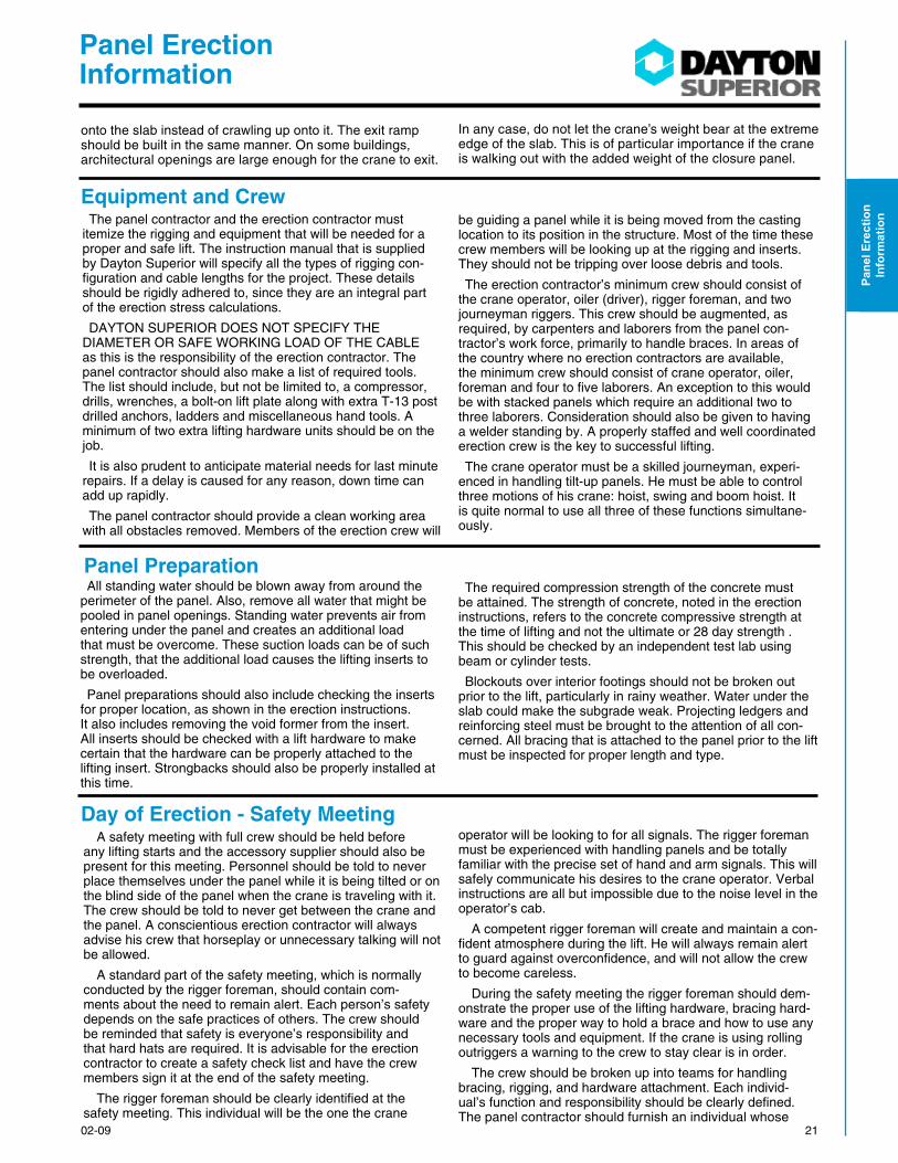
nThe panel contractor and the erection contractor must itemize the rigging and equipment that will be needed for a proper and safe lift. The instruction manual that is supplied by Dayton Superior will specify all the types of rigging con-figuration and cable lengths for the project. These details should be rigidly adhered to, since they are an integral part of the erection stress calculations.
DAYTON SUPERIOR DOES NOT SPECIFY THE DIAMETER OR SAFE WORKING LOAD OF THE CABLE as this is the responsibility of the erection contractor. The panel contractor should also make a list of required tools. The list should include, but not be limited to, a compressor, drills, wrenches, a bolt-on lift plate along with extra T-13 post drilled anchors, ladders and miscellaneous hand tools. A minimum of two extra lifting hardware units should be on the job.
It is also prudent to anticipate material needs for last minute repairs. If a delay is caused for any reason, down time can add up rapidly.
The panel contractor should provide a clean working area with all obstacles removed. Members of the erection crew will
be guiding a panel while it is being moved from the casting location to its position in the structure. Most of the time these crew members will be looking up at the rigging and inserts. They should not be tripping over loose debris and tools.
The erection contractor’s minimum crew should consist of the crane operator, oiler (driver), rigger foreman, and two journeyman riggers. This crew should be augmented, as required, by carpenters and laborers from the panel con-tractor’s work force, primarily to handle braces. In areas of the country where no erection contractors are available, the minimum crew should consist of crane operator, oiler, foreman and four to five laborers. An exception to this would be with stacked panels which require an additional two to three laborers. Consideration should also be given to having a welder standing by. A properly staffed and well coordinated erection crew is the key to successful lifting.
The crane operator must be a skilled journeyman, experi-enced in handling tilt-up panels. He must be able to control three motions of his crane: hoist, swing and boom hoist. It is quite normal to use all three of these functions simultane-ously.
All standing water should be blown away from around the perimeter of the panel. Also, remove all water that might be pooled in panel openings. Standing water prevents air from entering under the panel and creates an additional load that must be overcome. These suction loads can be of such strength, that the additional load causes the lifting inserts to be overloaded.
Panel preparations should also include checking the inserts for proper location, as shown in the erection instructions. It also includes removing the void former from the insert. All inserts should be checked with a lift hardware to make certain that the hardware can be properly attached to the lifting insert. Strongbacks should also be properly installed at this time.
The required compression strength of the concrete must be attained. The strength of concrete, noted in the erection instructions, refers to the concrete compressive strength at the time of lifting and not the ultimate or 28 day strength . This should be checked by an independent test lab using beam or cylinder tests.
Blockouts over interior footings should not be broken out prior to the lift, particularly in rainy weather. Water under the slab could make the subgrade weak. Projecting ledgers and reinforcing steel must be brought to the attention of all con-cerned. All bracing that is attached to the panel prior to the lift must be inspected for proper length and type.
A safety meeting with full crew should be held before any lifting starts and the accessory supplier should also be present for this meeting. Personnel should be told to never place themselves under the panel while it is being tilted or on the blind side of the panel when the crane is traveling with it. The crew should be told to never get between the crane and the panel. A conscientious erection contractor will always advise his crew that horseplay or unnecessary talking will not be allowed.
A standard part of the safety meeting, which is normally conducted by the rigger foreman, should contain com-ments about the need to remain alert. Each person’s safety depends on the safe practices of others. The crew should be reminded that safety is everyone’s responsibility and that hard hats are required. It is advisable for the erection contractor to create a safety check list and have the crew members sign it at the end of the safety meeting.
The rigger foreman should be clearly identified at the safety meeting. This individual will be the one the crane
operator will be looking to for all signals. The rigger foreman must be experienced with handling panels and be totally familiar with the precise set of hand and arm signals. This will safely communicate his desires to the crane operator. Verbal instructions are all but impossible due to the noise level in the operator’s cab.
A competent rigger foreman will create and maintain a con-fident atmosphere during the lift. He will always remain alert to guard against overconfidence, and will not allow the crew to become careless.
During the safety meeting the rigger foreman should dem-onstrate the proper use of the lifting hardware, bracing hard-ware and the proper way to hold a brace and how to use any necessary tools and equipment. If the crane is using rolling outriggers a warning to the crew to stay clear is in order.
The crew should be broken up into teams for handling bracing, rigging, and hardware attachment. Each individ-ual’s function and responsibility should be clearly defined. The panel contractor should furnish an individual whose
Equipment and Crew
Panel Preparation
Day of Erection - Safety Meeting
2102-09
onto the slab instead of crawling up onto it. The exit ramp should be built in the same manner. On some buildings, architectural openings are large enough for the crane to exit.
In any case, do not let the crane’s weight bear at the extreme edge of the slab. This is of particular importance if the crane is walking out with the added weight of the closure panel.

Panel Erection Information
Pane
l Ere
ctio
n In
form
atio
n
responsibility it is to clean the floor slab casting location as soon as the crane has lifted a panel and cleared the area. Regardless of how good a contractor’s housekeeping is prior to the lift, there is always a certain amount of debris left behind. This individual should also make certain that all left-over forming nails are pulled from the slab.
The rigging details furnished by Dayton Superior in the erection instructions are not merely simple guidelines from which the erector can stray. THE RIGGING DETAILS DEFINE THE PROPER RIGGING FOR EACH PANEL FOR THE ERECTOR. Spreader bar widths and cable angles are integral parts of the erection stress analysis.
Proper cable lengths are important to the success of the lift.
The use of cables that are shorter than the prescribed length will increase stresses in the panel and could cause the panel to crack. If an erector has a problem with rigging details or cable lengths, as they are shown in the erection instructions, he should not take it upon himself to change them. Instead, a call should be made to the technical service center from which the erection instructions originated. An alternate solution may be worked out depending on the indi-vidual situation.
Extra precautions should be taken when lifting panels with special shapes or special rigging. The erection instructions should be consulted for CAUTIONARY NOTES as to how a panel might act during lifting, and to again verify the rigging and the insert locations.
Wind conditions must be considered prior to lifting a panel. A 40-ton panel will easily move in a slight breeze when hanging from a crane. All spectators should be kept well away from the lift and not allowed to interfere with the pro-ceedings.
Panels should be inspected prior to lifting for any reinforc-ing steel and/or ledgers that may be projecting beyond the panel edges that will create interference when the panel is being plumbed next to a previously erected panel. This happens most often at corners.
After all attachments are made to the panel, and as the rigging is being raised to take the slack out of the cables, but prior to initial loading of the inserts, all rigging gear must be inspected for proper alignment and be free of snags. If non-swivel type sheaves are used, make certain the sheaves are properly aligned. As cables are being tensioned, they
invariably tend to twist and possibly rotate the lifting hard-ware causing side loading on the hardware. The rigger foreman should be alert for this condition and if it does happen, SHOULD HALT THE LIFT AND REALIGN THE HARDWARE.
It is the rigger foreman’s responsibility to be alert to all obstacles in the path of the crane and crew. He should be alert for panels that may be stuck to the casting surface. Under such conditions, loads transferred to the lifting inserts could be more than doubled causing possible insert failure. Carefully positioned, pry bars and wedges can often be successful in helping the crane release the panel from the casting surface. Any wedges that are applied to help release the panel should be positioned at the insert lines.
Braces are almost always attached to the panel prior to lifting. Caution must be taken to be certain the braces will not be trapped by the rigging when the panel is in the upright position.
Be alert when plumbing panels to their final upright posi-tion. Caution must be taken to make certain the panel being plumbed does not strike a previously erected panel. All personnel should be cleared of those critical areas around a panel when plumbing is being done. If the panel being plumbed is a closure panel, measurements should be taken prior to lifting to make certain the panel will fit.
Tilt-up panels should be as plumb as possible prior to attaching the brace to the floor attachment anchor. Temporary out-of-plumb-ness SHOULD NOT EXCEED 4” measured at the top of the panel. It is generally more practi-cal to “fine tune” the panel plumb-ness with the pipe braces after the lift is completed.
There are two commonly occurring conditions that dictate that the panels be braced perfectly plumb prior to releasing the crane:
1 ) If the panel is going to support an adjacent spandrel or lintel panel, the supporting panel should be in an accurate final position to prevent having to adjust it later when it is supporting another panel.
2) If the bracing design calls for a subsupport system of knee, lateral, and end or cross bracing, then the panel should be accurately plumbed prior to attaching the subsup-port system. Panels requiring subsupport systems must not be plumbed later as the brace subsupport system, if not removed, must be at least loosened in order to adjust the main brace, thus placing the panel in a dangerous position.
Do not release the crane load if, for any reason, the bracing does not appear adequate. Crane loads should always be released slowly, keeping an eye on the panel and bracing for any unusual activity. It is desirable that all bracing be com-plete before releasing the crane. That is, all knee, lateral, and end or cross bracing, if required, be in place. However, this is not always possible. You should always be able to install the knee bracing, however, the crane’s position near the panel
may prevent the lateral bracing from being attached.
Once the crane is clear of the area, the panel contractor must complete the lateral and end or cross bracing. He must complete this phase of the bracing while remaining no more than one panel behind the erection crew. All bracing should be completed on all erected panels at the end of the work day.
During the Lift Precautions
Plumbing Panels Precautions
Bracing General
22 02-09

Panel Erection Information
Pane
l Ere
ctio
n In
form
atio
n
Standard Rigging Details
Rigging is an integral factor in Dayton Supe-rior erection stress analysis. Rigging used on this project must conform to the rigging pattern speci-fied and shown on the panel layout sheet for that individual panel.
Use spreader and equalizer beams of such length that rigging cables are at a 90 ± 5 degree angle with the equalizer beams, unless otherwise shown or noted on the panel layout sheet.
The contractor must refer to the special infor-mation sheet for the minimum cable length to be used for each type of rigging specified in these erection details. Using shorter cables than speci-fied may overload inserts or crack panels.
Use of shorter cables or rigging patterns other than specified can cause insert failure, cracked panels, property damage, serious injury or death.
Cables must be of sufficient diameter to mini-mize stretch under load. Small diameter cables may have sufficient strength, but may stretch and cause the panel to bounce and result in increased insert loads.
The factor of safety used in the lifting design for these tilt-up panels is based on the panel being handled one time. Lifting and/or handling a panel more than one time could lead to property damage, serious injury or death.
Contact Dayton Superior Technical Service Center for proper rigging details before attempting to use two cranes dual-rigged to lift one panel. Improper dual-rigged cranes may overload inserts resulting in property damage, serious injury or death
WARNING
WARNING
WARNING
Spreader Beam
Snatch Block
(Typical)Spreader
Beam
Spreader Beam
Spreader Beam
Spreader Beam
Spreader Beam
Spreader BeamSpreader Beam
Lower Cable
Upper Cable
Equalizer Beams
Equalizer Beams
Lower Cable
Upper Cable
Lower Cable
Upper Cable
Equalizer Beams
Equalizer Beams
Main Cable
Main Cable
Snatch Block
(Typical)
R-21
R-22
R-02 R-12
R-41R-14
R-04 R-42
R-24 R-44Main Cable
Intermediate Cable
Snatch Block
(Typical)
Lower Cable
Upper Cable
R-82
2302-09

Panel Erection Information
Pane
l Ere
ctio
n In
form
atio
n
Boom PositioningTo safely erect a tilt-up panel, the crane boom must
be directly over the panel’s center of lift. If the boom is not correctly positioned the inserts have different loads than calculated in the erection analysis and the stresses in the panel will be greater than anticipated. If insert loads or panel stresses become too large, an insert will pull out of the con-crete or the panel will crack.
When the crane boom is set toward the bottom of the panel (under-booming) as the panel is erected, the panel will slide backwards. When the crane boom is set toward the top of the panel (over-booming) as the panel is erected, the panel will slide forward.
When a panel slides due to excessive under-booming or over-booming, it is possible for someone to be trapped between panels, between the panel and the crane, between panel braces, etc.
Plumbing Face-Lifted PanelsWhen a tilt-up panel is too tall to erect using edge lift in-
serts and the panel must hang as plumb as possible for set-ting, there are three standard methods available for use. One is the “plumbing block” method, the second is the “brace and re-rig” method and the third is the “transfer” method.
Plumbing Block MethodAfter erecting the panel to a vertical position, set the
panel on the ground and tip the panel so that the panel’s top edge rests against the rigging cables. Next, plumbing blocks supplied by others are placed around the cables and hooked over the top of the panel as shown below. The tendency of the cables to pull away from the panel will keep the plumbing blocks tight as the crane lifts the panel into position.
Over Booming
Under Booming
Incorrect Booming Panels will Slide
Up Face of Panel
Down Face of Panel
Plumbing Block
Correct Booming
Over Booming
Under Booming
Incorrect Booming Panels will Slide
Correct Booming
Plumbing blocks must be fabricated for each particular situation depending on the panel thickness and the number and diameter of cables. The plumbing blocks must fit securely over the thickness of the panel an the cables as shown.
NOTE: Rigging may vary from that shown.
WARNINGIncorrect placement of the crane boom can cause
over-stressing of the panel/inserts and possible sliding of the panel. Failure to correctly position the crane boom can cause property damage, serious injury or death
24 02-09

Panel Erection Information
Pane
l Ere
ctio
n In
form
atio
n
Brace and Re-rig Method
The “brace and re-rig” method is used when a crane does not have a second line that can safely carry the required panel weight. This method requires you to:
1) Erect the panel using the face lift inserts only.
2) Brace the panel as required.
3) Release the face lift hardware and rigging.
4) Reinstall the proper hardware and rigging onto the final set inserts.
5) With the rigging tight, remove the bracing.
6) Lift and set the panel into its final position.
7) Brace the panel as detailed.
8) Remove the final set lifting hardware and rigging.
Transfer Method
The “transfer” method is generally used when the crane has a second line that can safely carry the total panel weight. Using the transfer method requires:
1 That the panels be lifted to the vertical position using the face lift inserts and rigging only.
2) Keeping the rigging attached to the final set inserts slack with the final set hardware properly aligned with the cables.
3) After the panel is vertical and completely in the air, transfer the total panel load to the crane line and rigging attached to the final set inserts.
4) The panel is then set into its final position.
5) Brace the panel as detailed.
6) Release both the face lift and final set lifting hardware and rigging.
WARNING
1) Lift Panel With Face Lift Inserts
2) Brace Panel 3) Release Hardware
4) Re-Rig Panel 5) Remove Bracing6) Lift and Set Panel
7) Set and Brace 8) Remove Hardware
1) Lift Panel Using Face Inserts2) Edge Lift Rigging Remains Slack
3) Transferring Load To Edge Lift Inserts
4) Load Transfered and Panel Set In Place
5) Brace As Required 6) Release Hardware
NOTE: Rigging may vary from that shown.Failure to properly brace panels before releasing lifting hardware may cause failures resulting in injury or death.
2502-09

Panel Erection Information
Pane
l Ere
ctio
n In
form
atio
n
26 02-09