Embed Size (px)
Citation preview

Panel Mode ISPPanel Mode ISPDudley HillerDudley Hiller
Uwharrie Test Solutions LLCUwharrie Test Solutions LLC30-JUN-1530-JUN-15
Panel Mode ISPPanel Mode ISPDudley HillerDudley Hiller
Uwharrie Test Solutions LLCUwharrie Test Solutions LLC30-JUN-1530-JUN-15
• This presentation describes an In-System Programming technique that is gaining popularity on the Teradyne Test Station and GR228X, due to its increased throughput and cost savings.
• The advantage of Panel Mode ISP is you program all the units in the panel in the same time it takes to program a single unit.
• As with any new process there are new complications.• This slide show describes the technique, the benefits, the complications and
ways to overcome them.
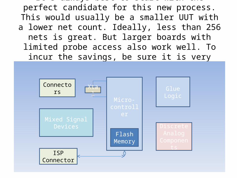
It’s always best to start with the perfect candidate for this new process. This would usually be a smaller UUT with a
lower net count. Ideally, less than 256 nets is great. But larger boards with limited probe access also work well. To incur the
savings, be sure it is very high volume.
Micro-controller
Glue Logic
Discrete Analog
Components
XtalConnectors
Mixed Signal Devices
Flash Memory
ISP Connector

And yes of course, they must be built in panels. They can be tooled as a panel, but they should also have
tooling available for each individual unit.
UUT (A)
UUT (B)
UUT (C)
UUT (D)
UUT (E)
UUT (F)
UUT (G)
UUT (H)
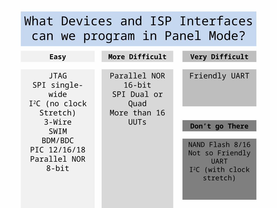
What Devices and ISP Interfaces can we program in Panel Mode?
Easy More Difficult Very Difficult
JTAGSPI single-wide
I2C (no clock Stretch)3-WireSWIM
BDM/BDCPIC 12/16/18
Parallel NOR 8-bit
Don’t go There
NAND Flash 8/16Not so Friendly UARTI2C (with clock stretch)
Parallel NOR 16-bitSPI Dual or Quad
More than 16 UUTs
Friendly UART

How are Panel ISP Solutions made?• The hybrid model does not generate the Panel Solution
automatically.• Generating the test program for the Panel Mode Solution is a
semi-automated process. I might totally automate this at some point. But for now I am doing this with an editor.
• The DSM datasets for most devices are automatically generated.
• If all bursts except for pre-verify can be immune to time-out and never use STOPONFAIL or a branch-out on failure then it will not be necessary to program each individual unit when a failure occurs. It is simpler just to accumulate a list of the failed units and report them at the end.
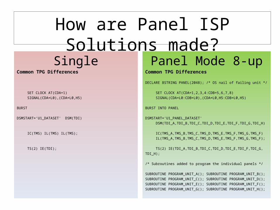
How are Panel ISP Solutions made?
SingleCommon TPG Differences
SET CLOCK AT(CDA=1)
SIGNAL(CDA=L0),(CDA=L0,H5)
BURST
DSMSTART=‘U1_DATASET' DSM(TDI)
IC(TMS) IL(TMS) IL(TMS);
TS(2) IE(TDI);
Panel Mode 8-upCommon TPG Differences
DECLARE BSTRING PANEL(2048); /* OS nail of failing unit */
SET CLOCK AT(CDA=1,2,3,4:CDB=5,6,7,8)
SIGNAL(CDA=L0:CDB=L0),(CDA=L0,H5:CDB=L0,H5)
BURST INTO PANEL
DSMSTART=‘U1_PANEL_DATASET'
DSM(TDI_A,TDI_B,TDI_C,TDI_D,TDI_E,TDI_F,TDI_G,TDI_H)
IC(TMS_A,TMS_B,TMS_C,TMS_D,TMS_E,TMS_F,TMS_G,TMS_F)
IL(TMS_A,TMS_B,TMS_C,TMS_D,TMS_E,TMS_F,TMS_G,TMS_F);
TS(2) IE(TDI_A,TDI_B,TDI_C,TDI_D,TDI_E,TDI_F,TDI_G,
TDI_H);
/* Subroutines added to program the individual panels */
SUBROUTINE PROGRAM_UNIT_A(); SUBROUTINE PROGRAM_UNIT_B();
SUBROUTINE PROGRAM_UNIT_C(); SUBROUTINE PROGRAM_UNIT_D();
SUBROUTINE PROGRAM_UNIT_E(); SUBROUTINE PROGRAM_UNIT_F();
SUBROUTINE PROGRAM_UNIT_G(); SUBROUTINE PROGRAM_UNIT_H();
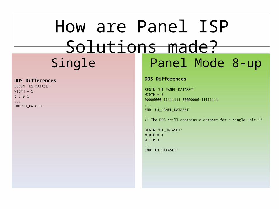
How are Panel ISP Solutions made?
SingleDDS DifferencesBEGIN 'U1_DATASET'
WIDTH = 1
0 1 0 1
...END 'U1_DATASET'
Panel Mode 8-upDDS Differences
BEGIN 'U1_PANEL_DATASET'
WIDTH = 8
00000000 11111111 00000000 11111111
...
END 'U1_PANEL_DATASET‘
/* The DDS still contains a dataset for a single unit */
BEGIN 'U1_DATASET'
WIDTH = 1
0 1 0 1
...
END 'U1_DATASET'
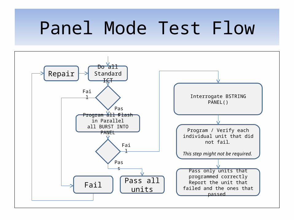
Panel Mode Test Flow
Do all
Standard ICT
Fail
Fail
Program all Flash in Parallelall BURST INTO PANEL
Pass
Pass
Fail
Pass all units
Interrogate BSTRING PANEL()
Program / Verify each individual unit that did not fail.
This step might not be required.
Pass only units that programmed correctly
Report the unit that failed and the ones that passed
Repair
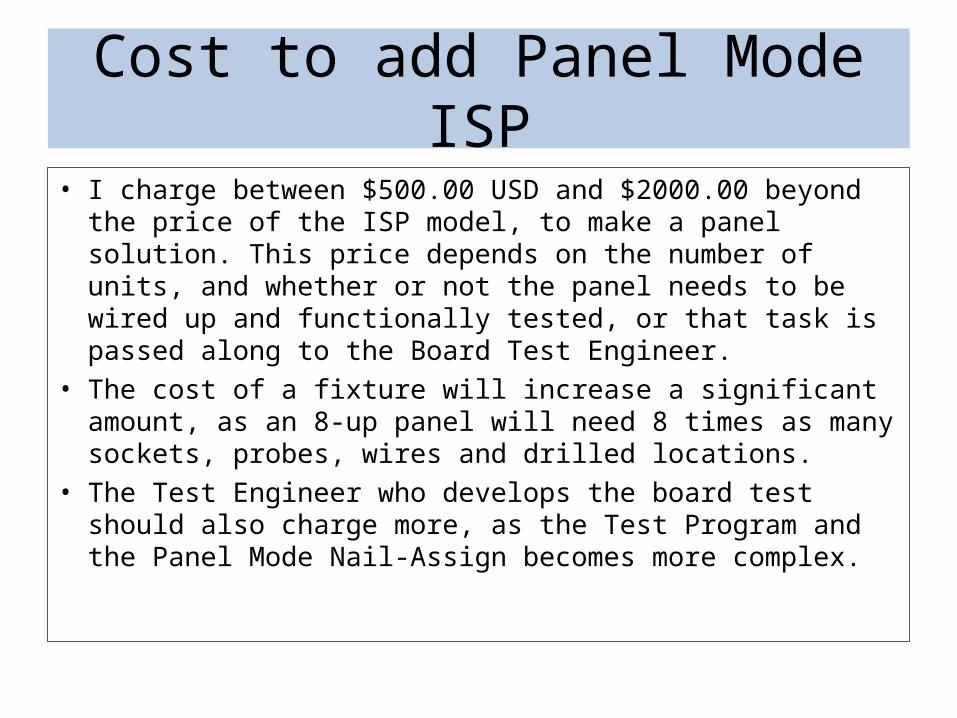
Cost to add Panel Mode ISP
• I charge between $500.00 USD and $2000.00 beyond the price of the ISP model, to make a panel solution. This price depends on the number of units, and whether or not the panel needs to be wired up and functionally tested, or that task is passed along to the Board Test Engineer.
• The cost of a fixture will increase a significant amount, as an 8-up panel will need 8 times as many sockets, probes, wires and drilled locations.
• The Test Engineer who develops the board test should also charge more, as the Test Program and the Panel Mode Nail-Assign becomes more complex.

Nail-Assign Panel-Assign Requirement
• If you do a panel of more that 2-up, the panel mode assignment must be done in the Unconstrained Mode. See: TestStation™ Panel Test, Serial Numbering, and Split Fixturing Manual. If you do the Offset Mode Panel-Assign, you will end up with a DSM mux conflict that you cannot resolve.– My opinion of Unconstrained Mode only is evolving. I am willing to try the offset mode.
But we will need to wire dual resources to the pins that connect to the Deep Serial Memory.
• I prefer to choose the set of nails to be used on the ISP signals of each unit (typically 4-5nails). Then the Board Test Engineer can force the Nail-Assign and Panel-Assign using an NDB or other Navigatetm method to force the assignment.
• I can functionally test the panel mode programming with the same nail set used by the fixture.
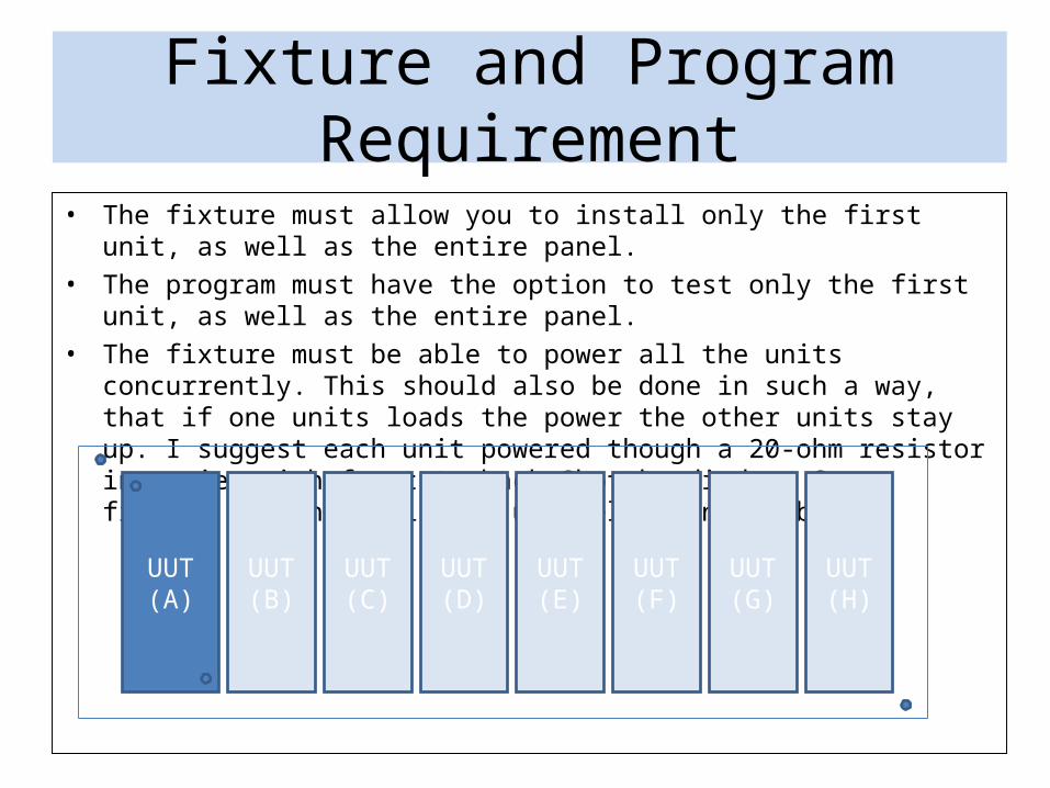
Fixture and Program Requirement
• The fixture must allow you to install only the first unit, as well as the entire panel.• The program must have the option to test only the first unit, as well as the entire
panel.• The fixture must be able to power all the units concurrently. This should also be
done in such a way, that if one units loads the power the other units stay up. I suggest each unit powered though a 20-ohm resistor in series with front to back Shottky diodes. Some fixture designers like to use relays, no problem.
UUT (A)
UUT (B)
UUT (C)
UUT (D)
UUT (E)
UUT (F)
UUT (G)
UUT (H)

Is it Tried and True?I sure hope so, or I may be getting some bad phone calls soon.
This chart shows panel mode programming already in volume production.
Device Units per panel
Flash size ISP interface
ISP Time per panel
Loc
MSP430F147 4 32KB+256B JTAG 2 sec MX
STM32F101RET 6 and 12 512K JTAG 24 sec EU
STM32F205RET 10 1MB JTAG 20.7 sec SD-US
ATSAM4S16BA 6 1MB JTAG 11.5 sec MX
ATMEGA32 2 32KB SPI 6.5 sec MX
STM8AF6266 7 32KB SWIM 5.4 sec MX
MC9S12XEG128MAA 3 128KB BDM 9.8 sec MX
UPD78F0572 15 16K UART 9.66 sec KY-US
SP3xx 30 15K I2C 2.1 sec xx-US
Any Disadvantage? Yes some…• Up-front DFT requirements, and convincing CAD
designers to do them.• The up-front costs could be prohibitive, if your volume is
not high enough.• Your process gets messy if your ICT yield falls below 99%.
Separation and re-test as singles may be required at times.
• Operators have to be trained to understand which units passed and which units failed if all units did not successfully program and verify
• Separation from panel happens after ICT, so ICT will not detect separation damage to the unit. Be careful there.
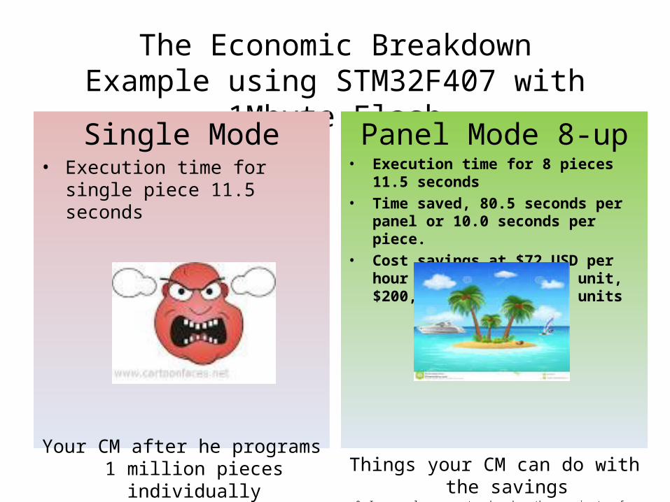
The Economic BreakdownExample using STM32F407 with 1Mbyte Flash
Single Mode• Execution time for single piece
11.5 seconds
Your CM after he programs 1 million pieces individually
Panel Mode 8-up• Execution time for 8 pieces 11.5 seconds• Time saved, 80.5 seconds per panel or 10.0
seconds per piece.• Cost savings at $72 USD per hour at ICT:
$0.20 per unit, $200,000 per 1 million units
Things your CM can do with the savings
Or I can supply an account number where they can wire-transfer what they don’t need

Conclusion
Panel Mode ISPThe Jury’s still out
Decide if it’s right for your process