Embed Size (px)
DESCRIPTION
Remote Stations from Pano logic
Citation preview
PANO LOGIC: REDBOOK PAGE 1
TABLE OF CONTENTS
VMware View Components 2 Basic Architecture 2 Hypervisor 2 Connection Brokers 3 DVM Provisioning and Management Tools 3 Platform Tools in DVMs 4
Hybrid Endpoint Populations 5
Scalability and Redundancy 6 Scalability on VMware View 6 Pano Scalability and Redundancy 6
Sample Architectures on VMware View 7 25-Seat Deployment 8 1,000-Seat Deployment 10
Pano Remote with VMware View 15
What Happens When a User Logs In 16
Differences Running on VMware 17 General Differences on View 17 Limitations with View Connection Server 17 Device-based Collections on View 18
More Information 19
Deploying Pano System
on VMware View
Redbook Virtualized Desktops running a standard Windows operating
system (OS) but hosted on centralized servers, promises to
radically reduce the ever-increasing drain on IT resources
from deploying and supporting desktop computing. Pano
Logic® is the first company to offer a complete, purpose-
built solution for full native Windows® virtual desktops,
combining a unique zero client endpoint with centralized
management tools designed specifically for managing
virtual desktops.
This redbook covers the basic architecture of deploying the
Pano System™ on the VMware® View™ platform,
explaining how it integrates with different required and
optional components included in the VMware View suite.
Overviews of different architecture, scalability and
availability configurations for both View and Pano System
components are discussed, along with detailed sample
deployment architectures for 25-, 1,000- and 10,000-seat
deployments and platform-specific differences and
limitations.
This redbook assumes that you have a good familiarity with
the operation of VMware View and with the basic structure
and operation of the Pano System. It does not replace the
installation instructions found in the View documentation
and in the Pano Logic online help. It provides platform-
specific details that supplement the more general Pano
deployment planning and infrastructure sizing guidance
provided by the Deployment Architecture Overview
Redbook, Infrastructure Sizing Redbook, and the Remote
Deployment Redbook.
DEPLOYING PANO SYSTEM ON VMWARE VIEW
PANO LOGIC: REDBOOK PAGE 2
VMware View Components
This section describes the various VMware View 4.5-5 components and describes how
they function in a Pano System deployment.
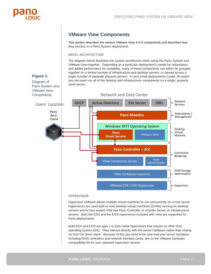
BASIC ARCHITECTURE
The diagram below illustrates the system architecture when using the Pano System and
VMware View together. Depending on a particular deployment’s needs for redundancy
and added performance for scalability, many of these components can either be grouped
together on a limited number of infrastructure and desktop servers, or spread across a
larger number of separate physical servers. In very small deployments (under 30 seats)
you can even run all of the desktop and infrastructure components on a single, properly
sized server.
HYPERVISOR
Hypervisor software allows multiple virtual machines to run concurrently on a host server.
Hypervisors are used both to host desktop virtual machines (DVMs) running on desktop
servers and to host system VMs like Pano Controller or vCenter Server on infrastructure
servers. Both the ESX and the ESXi hypervisors included with View are supported for
Pano deployments.
Both ESX and ESXi are type 1 or bare metal hypervisors that require no other host
operating system (OS). They interact directly with the server hardware rather than relying
on host OS driver stack. Because of this you need to be sure that your server hardware,
including RAID controllers and network interface cards, are on the VMware hardware
compatibility list for your selected hypervisor version.
Figure 1:
Diagram of
Pano System and
VMware View
Components
Pano Maestro
Active DirectoryDHCP DNS
View Connection Server
View Composer (optional)
Network and Data Center
Users’ Location
Pano Controller – ZCC
Pano Zero Client
Windows XP/7 Operating System
PanoDirect Service
VMware Tools
NetworkServicesFile Server
DesktopVirtualMachine
ConnectionBrokering
ViewAdministrator
DVM StorageOptimization
VMware ESX / ESXi Hypervisor Hypervisor
Redundancy /Management
DEPLOYING PANO SYSTEM ON VMWARE VIEW
PANO LOGIC: REDBOOK PAGE 3
CONNECTION BROKERS
VMware View Connection Server can be used to broker connections between Pano
clients and their virtual desktops, integrating with Pano Controller and replacing it as the
primary connection broker.
View Connection Server performs the following functions:
Connection brokering and single sign-on, including secure connections coming in
from a demilitarized zone (DMZ) network
Managing desktop virtual machine (DVM) sessions
User authentication with Active Directory®
Setting and applying user policies
Entitling users to specific desktops and pools based on an embedded LDAP
database
Providing the administration interface used by the View Administrator browser-
based interface
The connection brokering integration of Pano Controller with View Connection Server is
covered in more detail in the “What Happens When a User Logs In” on page 16.
View Connection Server also integrates with vCenter™ Server to provide enhanced
management capabilities beyond what is available in vCenter. These additions include
DVM creation (via View Composer), and managing DVM pools and power operations, like
automatic suspend and resume. When Pano Controller is integrated with View Connection
Server to use it as the primary connection broker only one DVM Collection of the special
“VMware View” type is created in Pano Controller. All DVMs will be provisioned by View,
rather than by Pano Controller, and will be automatically added to that DVM Collection.
View Connection Server requires a Windows Server® platform, which can be a virtual
machine or a dedicated physical server. The Connection Server is also dependent on
Active Directory – the supporting server or VM must be joined to an Active Directory
domain. When the server hosting the Connection Server is joined to the domain, a
computer object will automatically be created. You can use the web-based View
Administrator interface provided by the Connection Server to manage it.
Multiple View Connection Servers can be used, but since the connection servers
themselves do not provide load balancing, some external form of load balancing is
required. While there is a distinct option for Standard install vs. Replica install in the View
Connection Server installer, the new Connection Server is an equal peer of the original;
there is no master/slave relationship when additional Connection Servers are deployed.
View Connection Servers can also be configured as Security Servers when installed into a
DMZ network to act as a gateway. This configuration provides a secure, single point of
access from external networks, like the Internet for non-Pano connections from thin clients
and PC clients. However, this installation type is not required when using Pano Remote
as the Pano Gateway plug-in provides equivalent protection running on Windows Server
2008 R2 Remote Desktop Services.
DVM PROVISIONING AND MANAGEMENT TOOLS
vCenter Server is an advanced-configuration, deployment and provisioning tool for ESX
servers. vCenter is optional, but highly recommended for all but single ESXi server Pano
System deployments. vCenter Server integrates with Pano Controller to supplement DVM
collections and provide advanced provisioning options for DVMs.
When using the Pano System with vCenter Server, vCenter Server and optionally View
Composer perform all desktop provisioning services. Pano Controller will not cause any
DVMs to be created, nor will it attempt to keep a certain number of DVMs powered on.
These provisioning and power-management functions are all performed by vCenter
Server.
DEPLOYING PANO SYSTEM ON VMWARE VIEW
PANO LOGIC: REDBOOK PAGE 4
When using the Pano System with View Connection Server configured as the primary
connection broker, the DVM Collections tab must be configured for one, and only one,
DVM collection of type “VMware View.” DVMs provisioned by vCenter Server will be
automatically added to that DVM Collection.
vCenter can be run inside a Windows VM on the ESX/ESXI hypervisor – this is the
recommended configuration for Pano deployments.
View Composer is optional, but it can be used to optimize storage use in very large
VMware View deployments. View Composer enables you to stream a single desktop
image to create linked clones. This capability lets you quickly generate multiple virtual
desktops from a single DVM template on one or more servers in a data center. This facility
greatly reduces (by as much as 90%) the amount of storage required compared to other
methods of creating virtual desktop or DVM images. Linked clones also allow you to
update or configure a single DVM image rather than dozens or hundreds of DVM images,
significantly reducing the management overhead and workload.
Each linked clone is a duplicate copy of a parent virtual machine and shares files and disk
space with its parent virtual machine. This commonality allows linked clones to take up
less physical space on virtual disks, while still allowing them to share the software
installed on their parent virtual machines. Each linked clone can operate with its own IP
address and hostname, while minimizing the amount of disk space it occupies. You can
automate the process of installing software patches/updates by installing the changes on
the parent virtual machines and then pushing these changes onto their linked clones. This
functionality is especially useful in large VMware View deployments.
View Administrator is the web-based application used to administer View Connection
Server. On the Access tab, specify the accounts that are to have access to the DVMs. The
simplest approach is to specify a security group that includes all domain users. Even
though all users would be entitled within Pano Controller, the user entitlements defined in
View Administrator will still be used to implement more specific user-to-desktop mappings.
Thus, if an account is entitled in Pano Controller but not in View Administrator, the user
will be prevented from connecting to a desktop.
PLATFORM TOOLS IN DVMS
All Desktop Virtual Machines (DVMs), of which you will typically have many in your
deployment, will need to have both the Pano Direct Service™ (PDS) software and
platform-specific add-ins or tool software installed directly in the Windows operating
system. Each DVM must have the VMware Tools software installed. These tools are
required in order for the ESX or ESXi hypervisor to manage the state of the DVM. Without
these tools installed, VMware View’s components will consider the DVM to be unavailable.

DEPLOYING PANO SYSTEM ON VMWARE VIEW
PANO LOGIC: REDBOOK PAGE 5
Hybrid Endpoint Populations
VMware View can provide a unified DVM management and provisioning system for hybrid
populations of endpoints that mix Pano Zero Clients with traditional thin clients and PCs
running the View Client software. While all of these endpoints can benefit from the
management, provisioning and connection brokering functionality provided by View’s
components, there are a number of differences in how they operate.
Key differences between Pano Zero Clients and other types of View clients are:
Pano clients still require Pano Controller to provide login dialogs and initiate
connection brokering. Because of this, if the number of Pano clients exceeds
500, you’ll need to deploy additional Pano Controller instances in a scalability
group.
Pano clients use the Pano Direct Protocol rather than the Remote Desktop
Protocol (RDP) or PC-over-IP protocols used by other View clients. This
shouldn’t have a direct impact on your deployment unless you are using protocol-
based routing or quality-of-service prioritization; in which case, you may need to
include all three protocols.
Pano clients require that you install Pano Direct Service into the Windows DVMs
in addition to VMware Tools, while most other View clients require only VMware
Tools. You can still access the same DVMs from both Pano Zero Clients (and
from Pano Remote) and from other View endpoints, including thin clients or even
tablets running software like the View Client for iPad.
Some View clients support connections over WANs with lower bandwidth and
higher latencies than Pano Zero Clients support. You can mix in WAN access via
these clients with access via Pano Zero Clients over LAN-quality connections to
the desktop server hosting the DVMs. Or, you can use Pano Remote when users
need WAN-based connections to their DVMs, which is roughly equivalent to the
RDP-based View Client software running on Windows PCs or laptops.
Figure 2:
Hybrid Endpoints
managed by
View and Pano
Controller
Data CenterUsers‘ Location
PanoZero
Clients
ThinClients
PCsrunning
ViewClient
Infrastructure Servers
vCenterServer
View Connection
Server
View Composer
Pano ControllerES
X /
ESX
i Hyp
ervi
sor
DomainServers
Directory Services
DHCP
Desktop Servers
Win XP/7DVMs
Pano Direct Service
VMware Tools
Edge Network Core Network
Management Workstation
ESX / ESXi HypervisorPano
Maestro
DEPLOYING PANO SYSTEM ON VMWARE VIEW
PANO LOGIC: REDBOOK PAGE 6
View clients accessing DVMs from unsecured networks like the Internet typically
connect via an intervening View Security Server (a specialized installation of the
View Connection Server) residing in a DMZ network protected by firewalls. Pano
Remote clients use a similar architecture, but use Pano Gateway running on
Windows Server 2008 Remote Desktop Services in the DMZ rather than using a
View Security server.
Unlike software-free Pano Zero Clients, both thin clients and repurposed PCs
acting as platforms for View Client need a full operating system and software
stack running on the endpoint itself. Required maintenance usually includes
software/OS patch management, security suite installation/updates and client OS
image provisioning and backup. Some of the maintenance overhead on non-zero
clients can be reduced by implementing write-filters and policy changes that lock-
down the configuration and prevent changes by users or malware.
Scalability and Redundancy
For larger deployments on the VMware View platform, it may be necessary to use optional
VMware View components and configurations, in addition to multiple instances of these
components and Pano Controller, to provide both greater scalability and improved
availability via redundancy.
SCALABILITY ON VMWARE VIEW
For deployments larger than 500 seats, you will need to use a Pano Controller group that
combines two to six Pano Controller instances to provide redundancy for up to 2,000 Pano
Zero Clients and DVMs.
For Pano System deployments on VMware View with up to 10,000 endpoints, you may
need to also integrate View Connection Server as the primary connection broker,
replacing the Virtual Desktop Broker (VDB) or Full Roles of your Pano Controllers. In very
large deployments, you may also need to deploy multiple instances of the View
Connection Server running on separate physical servers. If multiple Connection Servers
are used some form of load-balancer is required to distribute the connection request to
these servers.
Pano Controller is still used, via its Zero Client Controller (ZCC) Role, during the
connection brokering process to provide the client login dialogs. Pano Controller is also
still used to monitor Pano Zero Clients and Pano Remote Clients. For more details on the
shared login and connection brokering process see “What Happens When a User Logs In”
on page 16.
PANO SCALABILITY AND REDUNDANCY
If we also want to provide redundancy or failover capabilities in the event of server
hardware or software failure, two Pano Controller instances need to be installed on two
different physical servers and configured as primary (active) and secondary (passive), and
a third Pano Controller instance would be added and configured as a slave.
DEPLOYING PANO SYSTEM ON VMWARE VIEW
PANO LOGIC: REDBOOK PAGE 7
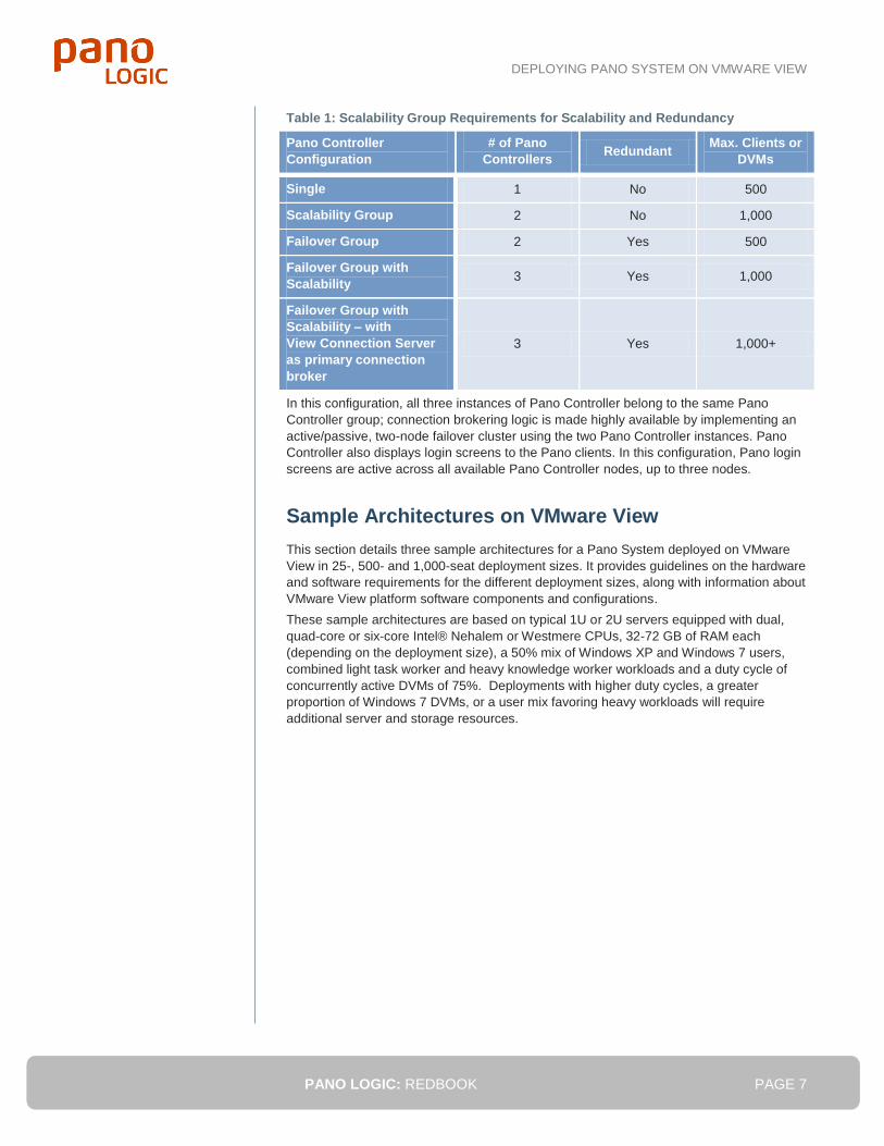
Table 1: Scalability Group Requirements for Scalability and Redundancy
Pano Controller
Configuration
# of Pano
Controllers Redundant
Max. Clients or
DVMs
Single 1 No 500
Scalability Group 2 No 1,000
Failover Group 2 Yes 500
Failover Group with
Scalability 3 Yes 1,000
Failover Group with
Scalability – with
View Connection Server
as primary connection
broker
3 Yes 1,000+
In this configuration, all three instances of Pano Controller belong to the same Pano
Controller group; connection brokering logic is made highly available by implementing an
active/passive, two-node failover cluster using the two Pano Controller instances. Pano
Controller also displays login screens to the Pano clients. In this configuration, Pano login
screens are active across all available Pano Controller nodes, up to three nodes.
Sample Architectures on VMware View
This section details three sample architectures for a Pano System deployed on VMware
View in 25-, 500- and 1,000-seat deployment sizes. It provides guidelines on the hardware
and software requirements for the different deployment sizes, along with information about
VMware View platform software components and configurations.
These sample architectures are based on typical 1U or 2U servers equipped with dual,
quad-core or six-core Intel® Nehalem or Westmere CPUs, 32-72 GB of RAM each
(depending on the deployment size), a 50% mix of Windows XP and Windows 7 users,
combined light task worker and heavy knowledge worker workloads and a duty cycle of
concurrently active DVMs of 75%. Deployments with higher duty cycles, a greater
proportion of Windows 7 DVMs, or a user mix favoring heavy workloads will require
additional server and storage resources.
DEPLOYING PANO SYSTEM ON VMWARE VIEW
PANO LOGIC: REDBOOK PAGE 8
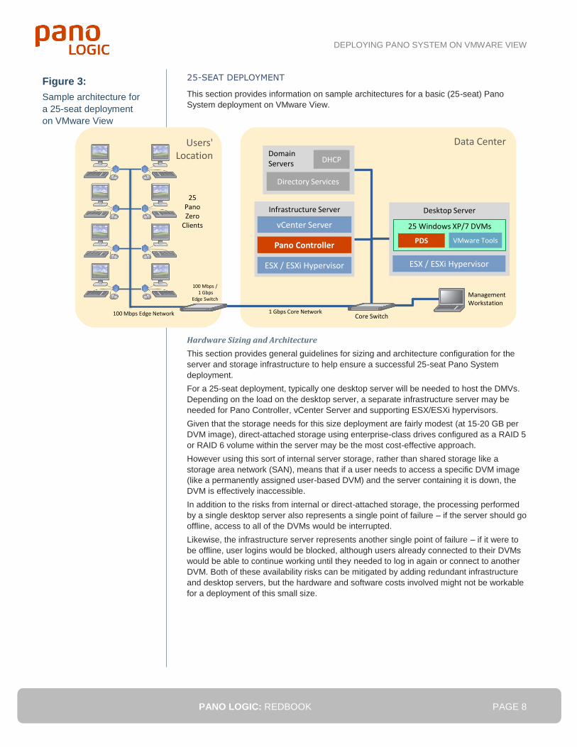
25-SEAT DEPLOYMENT
This section provides information on sample architectures for a basic (25-seat) Pano
System deployment on VMware View.
Hardware Sizing and Architecture
This section provides general guidelines for sizing and architecture configuration for the
server and storage infrastructure to help ensure a successful 25-seat Pano System
deployment.
For a 25-seat deployment, typically one desktop server will be needed to host the DMVs.
Depending on the load on the desktop server, a separate infrastructure server may be
needed for Pano Controller, vCenter Server and supporting ESX/ESXi hypervisors.
Given that the storage needs for this size deployment are fairly modest (at 15-20 GB per
DVM image), direct-attached storage using enterprise-class drives configured as a RAID 5
or RAID 6 volume within the server may be the most cost-effective approach.
However using this sort of internal server storage, rather than shared storage like a
storage area network (SAN), means that if a user needs to access a specific DVM image
(like a permanently assigned user-based DVM) and the server containing it is down, the
DVM is effectively inaccessible.
In addition to the risks from internal or direct-attached storage, the processing performed
by a single desktop server also represents a single point of failure – if the server should go
offline, access to all of the DVMs would be interrupted.
Likewise, the infrastructure server represents another single point of failure – if it were to
be offline, user logins would be blocked, although users already connected to their DVMs
would be able to continue working until they needed to log in again or connect to another
DVM. Both of these availability risks can be mitigated by adding redundant infrastructure
and desktop servers, but the hardware and software costs involved might not be workable
for a deployment of this small size.
Figure 3:
Sample architecture for
a 25-seat deployment
on VMware View
Data Center
Desktop Server
Users'Location
25PanoZero
Clients
Management Workstation
100 Mbps Edge Network 1 Gbps Core Network
25 Windows XP/7 DVMs
PDS
ESX / ESXi Hypervisor
Infrastructure Server
Pano Controller
vCenter Server
ESX / ESXi Hypervisor
DomainServers
Directory Services
DHCP
Core Switch
VMware Tools
100 Mbps /1 Gbps
Edge Switch
DEPLOYING PANO SYSTEM ON VMWARE VIEW
PANO LOGIC: REDBOOK PAGE 9
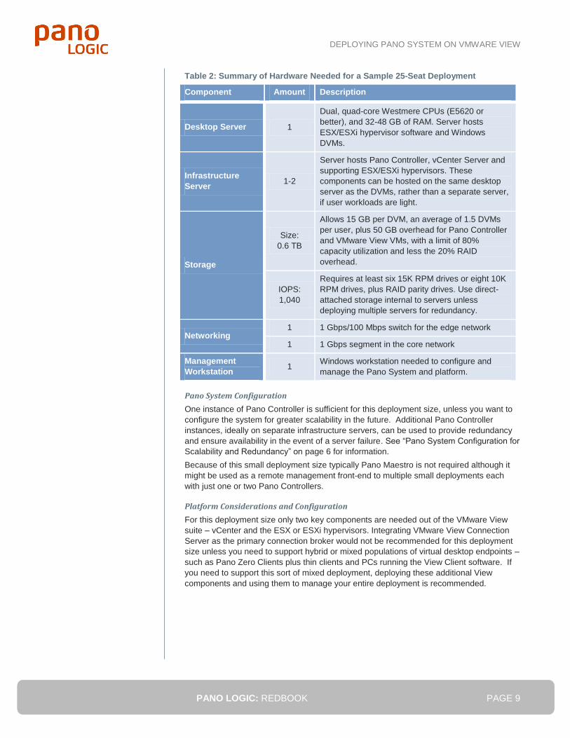
Table 2: Summary of Hardware Needed for a Sample 25-Seat Deployment
Component Amount Description
Desktop Server 1
Dual, quad-core Westmere CPUs (E5620 or
better), and 32-48 GB of RAM. Server hosts
ESX/ESXi hypervisor software and Windows
DVMs.
Infrastructure
Server 1-2
Server hosts Pano Controller, vCenter Server and
supporting ESX/ESXi hypervisors. These
components can be hosted on the same desktop
server as the DVMs, rather than a separate server,
if user workloads are light.
Storage
Size:
0.6 TB
Allows 15 GB per DVM, an average of 1.5 DVMs
per user, plus 50 GB overhead for Pano Controller
and VMware View VMs, with a limit of 80%
capacity utilization and less the 20% RAID
overhead.
IOPS:
1,040
Requires at least six 15K RPM drives or eight 10K
RPM drives, plus RAID parity drives. Use direct-
attached storage internal to servers unless
deploying multiple servers for redundancy.
Networking 1 1 Gbps/100 Mbps switch for the edge network
1 1 Gbps segment in the core network
Management
Workstation 1
Windows workstation needed to configure and
manage the Pano System and platform.
Pano System Configuration
One instance of Pano Controller is sufficient for this deployment size, unless you want to
configure the system for greater scalability in the future. Additional Pano Controller
instances, ideally on separate infrastructure servers, can be used to provide redundancy
and ensure availability in the event of a server failure. See “Pano System Configuration for
Scalability and Redundancy” on page 6 for information.
Because of this small deployment size typically Pano Maestro is not required although it
might be used as a remote management front-end to multiple small deployments each
with just one or two Pano Controllers.
Platform Considerations and Configuration
For this deployment size only two key components are needed out of the VMware View
suite – vCenter and the ESX or ESXi hypervisors. Integrating VMware View Connection
Server as the primary connection broker would not be recommended for this deployment
size unless you need to support hybrid or mixed populations of virtual desktop endpoints –
such as Pano Zero Clients plus thin clients and PCs running the View Client software. If
you need to support this sort of mixed deployment, deploying these additional View
components and using them to manage your entire deployment is recommended.
DEPLOYING PANO SYSTEM ON VMWARE VIEW
PANO LOGIC: REDBOOK PAGE 10
Table 3: Summary of Software Needed for a Sample 25-Seat Deployment
Component Number Description
Pano Controller VM 1-2
Only one is required, unless you use a Pano
Controller group. (You should install additional
Pano Manger instances on separate servers to
protect against server failure.)
ESX/ESXi Hypervisor 2-3
Only one per server is required, unless you use
a Pano Controller group for redundancy on
separate servers.
View Connection
Server 1
Optional – if used, can be hosted on the same
desktop server as the DVMs and Pano
Controller.
vCenter Server 1
Provides DVM management capabilities for
Pano Controller and VMware View. Can run
inside a Windows VM.
View Composer optional Not recommended because linked clones are
not recommended at this deployment size.
In most cases, View Composer, which is used for storage deduplication across sets of
similar DVM images, can typically be omitted, as well. This is due to the fact that the
storage requirements for 25 DVM images, plus any other DVM templates, aren’t enough
to warrant the added complexity and cost of licensing (as part of View Premier Edition)
and deploying View Composer.
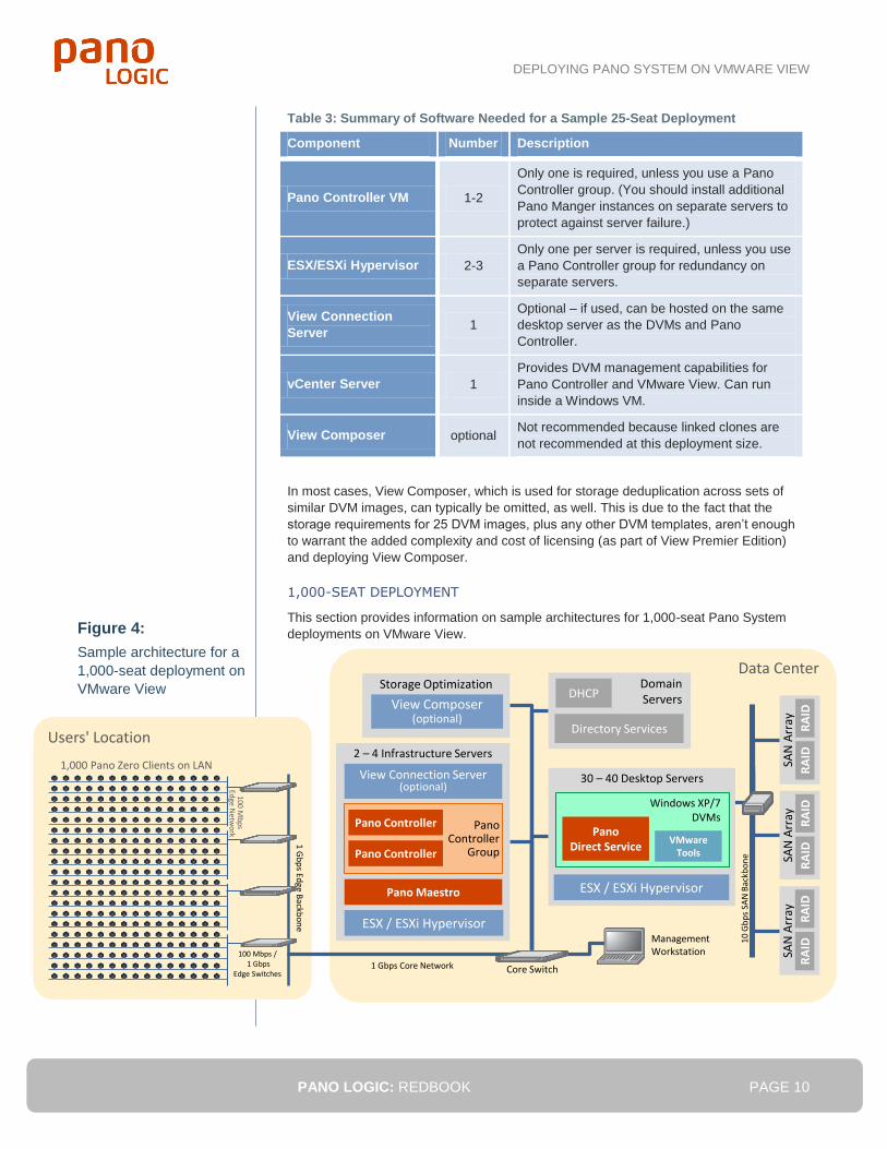
1,000-SEAT DEPLOYMENT
This section provides information on sample architectures for 1,000-seat Pano System
deployments on VMware View.
Figure 4:
Sample architecture for a
1,000-seat deployment on
VMware View
Users' Location
100 Mb
ps
Edge N
etwo
rk
1,000 Pano Zero Clients on LAN
Data Center
SAN
Arr
ay
RA
IDR
AID
10
Gb
ps
SAN
Bac
kbo
ne
SAN
Arr
ay
RA
IDR
AID
SAN
Arr
ay
RA
IDR
AID
Storage Optimization
30 – 40 Desktop Servers
Management Workstation
1 Gbps Core Network
Windows XP/7DVMs
PanoDirect Service
ESX / ESXi Hypervisor
View Composer (optional)
DomainServers
Directory Services
DHCP
Core Switch
2 – 4 Infrastructure Servers
View Connection Server (optional)
ESX / ESXi Hypervisor
Pano Controller
Group
Pano Controller
Pano ControllerVMware
Tools
100 Mbps /1 Gbps
Edge Switches
1 G
bp
s Edge B
ackbo
ne
Pano Maestro
DEPLOYING PANO SYSTEM ON VMWARE VIEW
PANO LOGIC: REDBOOK PAGE 11
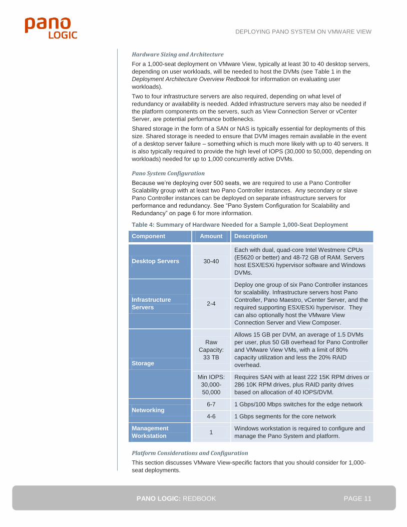
Hardware Sizing and Architecture
For a 1,000-seat deployment on VMware View, typically at least 30 to 40 desktop servers,
depending on user workloads, will be needed to host the DVMs (see Table 1 in the
Deployment Architecture Overview Redbook for information on evaluating user
workloads).
Two to four infrastructure servers are also required, depending on what level of
redundancy or availability is needed. Added infrastructure servers may also be needed if
the platform components on the servers, such as View Connection Server or vCenter
Server, are potential performance bottlenecks.
Shared storage in the form of a SAN or NAS is typically essential for deployments of this
size. Shared storage is needed to ensure that DVM images remain available in the event
of a desktop server failure – something which is much more likely with up to 40 servers. It
is also typically required to provide the high level of IOPS (30,000 to 50,000, depending on
workloads) needed for up to 1,000 concurrently active DVMs.
Pano System Configuration
Because we’re deploying over 500 seats, we are required to use a Pano Controller
Scalability group with at least two Pano Controller instances. Any secondary or slave
Pano Controller instances can be deployed on separate infrastructure servers for
performance and redundancy. See “Pano System Configuration for Scalability and
Redundancy” on page 6 for more information.
Table 4: Summary of Hardware Needed for a Sample 1,000-Seat Deployment
Component Amount Description
Desktop Servers 30-40
Each with dual, quad-core Intel Westmere CPUs
(E5620 or better) and 48-72 GB of RAM. Servers
host ESX/ESXi hypervisor software and Windows
DVMs.
Infrastructure
Servers 2-4
Deploy one group of six Pano Controller instances
for scalability. Infrastructure servers host Pano
Controller, Pano Maestro, vCenter Server, and the
required supporting ESX/ESXi hypervisor. They
can also optionally host the VMware View
Connection Server and View Composer.
Storage
Raw
Capacity:
33 TB
Allows 15 GB per DVM, an average of 1.5 DVMs
per user, plus 50 GB overhead for Pano Controller
and VMware View VMs, with a limit of 80%
capacity utilization and less the 20% RAID
overhead.
Min IOPS:
30,000-
50,000
Requires SAN with at least 222 15K RPM drives or
286 10K RPM drives, plus RAID parity drives
based on allocation of 40 IOPS/DVM.
Networking 6-7 1 Gbps/100 Mbps switches for the edge network
4-6 1 Gbps segments for the core network
Management
Workstation 1
Windows workstation is required to configure and
manage the Pano System and platform.
Platform Considerations and Configuration
This section discusses VMware View-specific factors that you should consider for 1,000-
seat deployments.
DEPLOYING PANO SYSTEM ON VMWARE VIEW
PANO LOGIC: REDBOOK PAGE 12
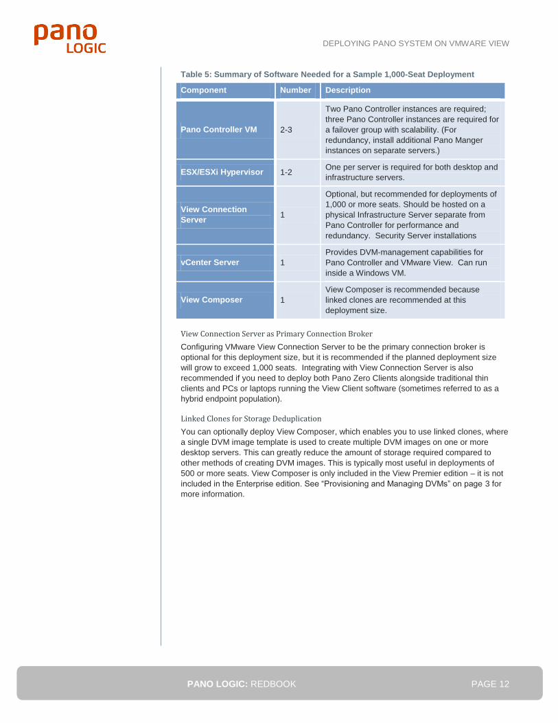
Table 5: Summary of Software Needed for a Sample 1,000-Seat Deployment
Component Number Description
Pano Controller VM 2-3
Two Pano Controller instances are required;
three Pano Controller instances are required for
a failover group with scalability. (For
redundancy, install additional Pano Manger
instances on separate servers.)
ESX/ESXi Hypervisor 1-2 One per server is required for both desktop and
infrastructure servers.
View Connection
Server 1
Optional, but recommended for deployments of
1,000 or more seats. Should be hosted on a
physical Infrastructure Server separate from
Pano Controller for performance and
redundancy. Security Server installations
vCenter Server 1
Provides DVM-management capabilities for
Pano Controller and VMware View. Can run
inside a Windows VM.
View Composer 1
View Composer is recommended because
linked clones are recommended at this
deployment size.
View Connection Server as Primary Connection Broker
Configuring VMware View Connection Server to be the primary connection broker is
optional for this deployment size, but it is recommended if the planned deployment size
will grow to exceed 1,000 seats. Integrating with View Connection Server is also
recommended if you need to deploy both Pano Zero Clients alongside traditional thin
clients and PCs or laptops running the View Client software (sometimes referred to as a
hybrid endpoint population).
Linked Clones for Storage Deduplication
You can optionally deploy View Composer, which enables you to use linked clones, where
a single DVM image template is used to create multiple DVM images on one or more
desktop servers. This can greatly reduce the amount of storage required compared to
other methods of creating DVM images. This is typically most useful in deployments of
500 or more seats. View Composer is only included in the View Premier edition – it is not
included in the Enterprise edition. See “Provisioning and Managing DVMs” on page 3 for
more information.
DEPLOYING PANO SYSTEM ON VMWARE VIEW
PANO LOGIC: REDBOOK PAGE 13
¿10,000-Seat Deployment
This section provides information on sample architectures for 10,000-seat Pano System
deployments on VMware View.
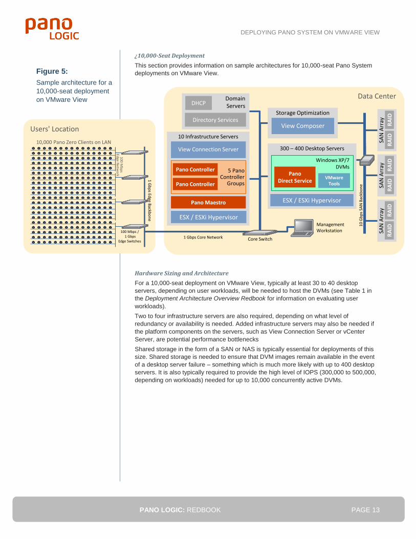
Hardware Sizing and Architecture
For a 10,000-seat deployment on VMware View, typically at least 30 to 40 desktop
servers, depending on user workloads, will be needed to host the DVMs (see Table 1 in
the Deployment Architecture Overview Redbook for information on evaluating user
workloads).
Two to four infrastructure servers are also required, depending on what level of
redundancy or availability is needed. Added infrastructure servers may also be needed if
the platform components on the servers, such as View Connection Server or vCenter
Server, are potential performance bottlenecks
Shared storage in the form of a SAN or NAS is typically essential for deployments of this
size. Shared storage is needed to ensure that DVM images remain available in the event
of a desktop server failure – something which is much more likely with up to 400 desktop
servers. It is also typically required to provide the high level of IOPS (300,000 to 500,000,
depending on workloads) needed for up to 10,000 concurrently active DVMs.
Figure 5:
Sample architecture for a
10,000-seat deployment
on VMware View
Users' Location
100 Mb
ps
Edge N
etwo
rk
10,000 Pano Zero Clients on LAN
Data Center
SAN
Arr
ay
RA
IDR
AID
10
Gb
ps
SAN
Bac
kbo
ne
SAN
Arr
ay
RA
IDR
AID
SAN
Arr
ay
RA
IDR
AID
300 – 400 Desktop Servers
Management Workstation
1 Gbps Core Network
Windows XP/7DVMs
PanoDirect Service
ESX / ESXi Hypervisor
DomainServers
Directory Services
DHCP
Core Switch
10 Infrastructure Servers
View Connection Server
ESX / ESXi Hypervisor
5 Pano Controller
Groups
Pano Controller
Pano ControllerVMware
Tools
100 Mbps /1 Gbps
Edge Switches
1 G
bp
s Edge B
ackbo
ne
Pano Maestro
Storage Optimization
View Composer
DEPLOYING PANO SYSTEM ON VMWARE VIEW
PANO LOGIC: REDBOOK PAGE 14
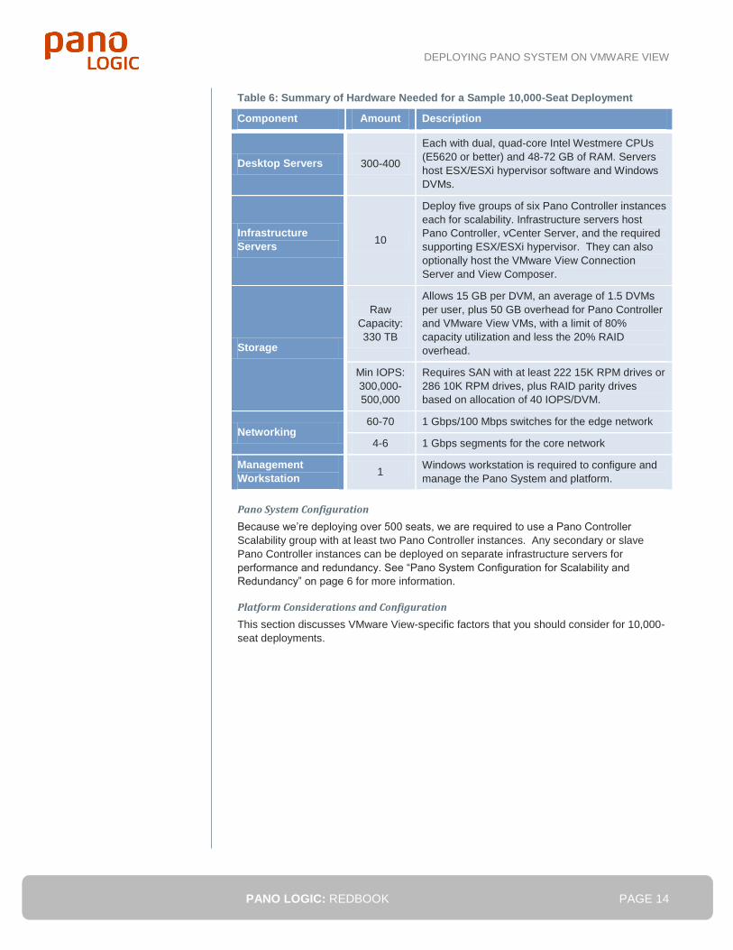
Table 6: Summary of Hardware Needed for a Sample 10,000-Seat Deployment
Component Amount Description
Desktop Servers 300-400
Each with dual, quad-core Intel Westmere CPUs
(E5620 or better) and 48-72 GB of RAM. Servers
host ESX/ESXi hypervisor software and Windows
DVMs.
Infrastructure
Servers 10
Deploy five groups of six Pano Controller instances
each for scalability. Infrastructure servers host
Pano Controller, vCenter Server, and the required
supporting ESX/ESXi hypervisor. They can also
optionally host the VMware View Connection
Server and View Composer.
Storage
Raw
Capacity:
330 TB
Allows 15 GB per DVM, an average of 1.5 DVMs
per user, plus 50 GB overhead for Pano Controller
and VMware View VMs, with a limit of 80%
capacity utilization and less the 20% RAID
overhead.
Min IOPS:
300,000-
500,000
Requires SAN with at least 222 15K RPM drives or
286 10K RPM drives, plus RAID parity drives
based on allocation of 40 IOPS/DVM.
Networking 60-70 1 Gbps/100 Mbps switches for the edge network
4-6 1 Gbps segments for the core network
Management
Workstation 1
Windows workstation is required to configure and
manage the Pano System and platform.
Pano System Configuration
Because we’re deploying over 500 seats, we are required to use a Pano Controller
Scalability group with at least two Pano Controller instances. Any secondary or slave
Pano Controller instances can be deployed on separate infrastructure servers for
performance and redundancy. See “Pano System Configuration for Scalability and
Redundancy” on page 6 for more information.
Platform Considerations and Configuration
This section discusses VMware View-specific factors that you should consider for 10,000-
seat deployments.
DEPLOYING PANO SYSTEM ON VMWARE VIEW
PANO LOGIC: REDBOOK PAGE 15
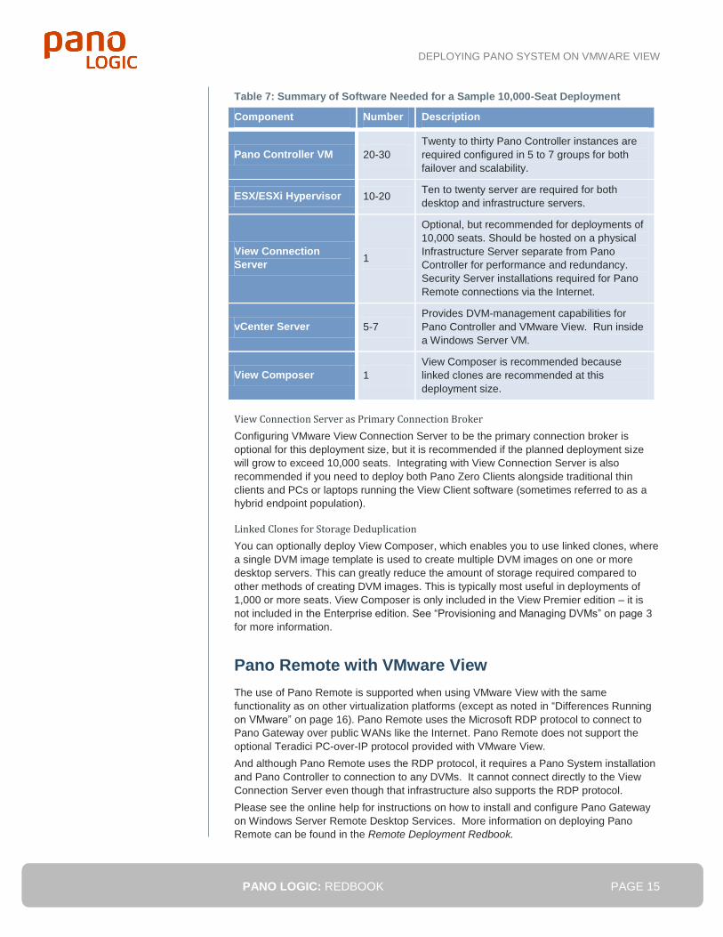
Table 7: Summary of Software Needed for a Sample 10,000-Seat Deployment
Component Number Description
Pano Controller VM 20-30
Twenty to thirty Pano Controller instances are
required configured in 5 to 7 groups for both
failover and scalability.
ESX/ESXi Hypervisor 10-20 Ten to twenty server are required for both
desktop and infrastructure servers.
View Connection
Server 1
Optional, but recommended for deployments of
10,000 seats. Should be hosted on a physical
Infrastructure Server separate from Pano
Controller for performance and redundancy.
Security Server installations required for Pano
Remote connections via the Internet.
vCenter Server 5-7
Provides DVM-management capabilities for
Pano Controller and VMware View. Run inside
a Windows Server VM.
View Composer 1
View Composer is recommended because
linked clones are recommended at this
deployment size.
View Connection Server as Primary Connection Broker
Configuring VMware View Connection Server to be the primary connection broker is
optional for this deployment size, but it is recommended if the planned deployment size
will grow to exceed 10,000 seats. Integrating with View Connection Server is also
recommended if you need to deploy both Pano Zero Clients alongside traditional thin
clients and PCs or laptops running the View Client software (sometimes referred to as a
hybrid endpoint population).
Linked Clones for Storage Deduplication
You can optionally deploy View Composer, which enables you to use linked clones, where
a single DVM image template is used to create multiple DVM images on one or more
desktop servers. This can greatly reduce the amount of storage required compared to
other methods of creating DVM images. This is typically most useful in deployments of
1,000 or more seats. View Composer is only included in the View Premier edition – it is
not included in the Enterprise edition. See “Provisioning and Managing DVMs” on page 3
for more information.
Pano Remote with VMware View
The use of Pano Remote is supported when using VMware View with the same
functionality as on other virtualization platforms (except as noted in “Differences Running
on VMware” on page 16). Pano Remote uses the Microsoft RDP protocol to connect to
Pano Gateway over public WANs like the Internet. Pano Remote does not support the
optional Teradici PC-over-IP protocol provided with VMware View.
And although Pano Remote uses the RDP protocol, it requires a Pano System installation
and Pano Controller to connection to any DVMs. It cannot connect directly to the View
Connection Server even though that infrastructure also supports the RDP protocol.
Please see the online help for instructions on how to install and configure Pano Gateway
on Windows Server Remote Desktop Services. More information on deploying Pano
Remote can be found in the Remote Deployment Redbook.
DEPLOYING PANO SYSTEM ON VMWARE VIEW
PANO LOGIC: REDBOOK PAGE 16
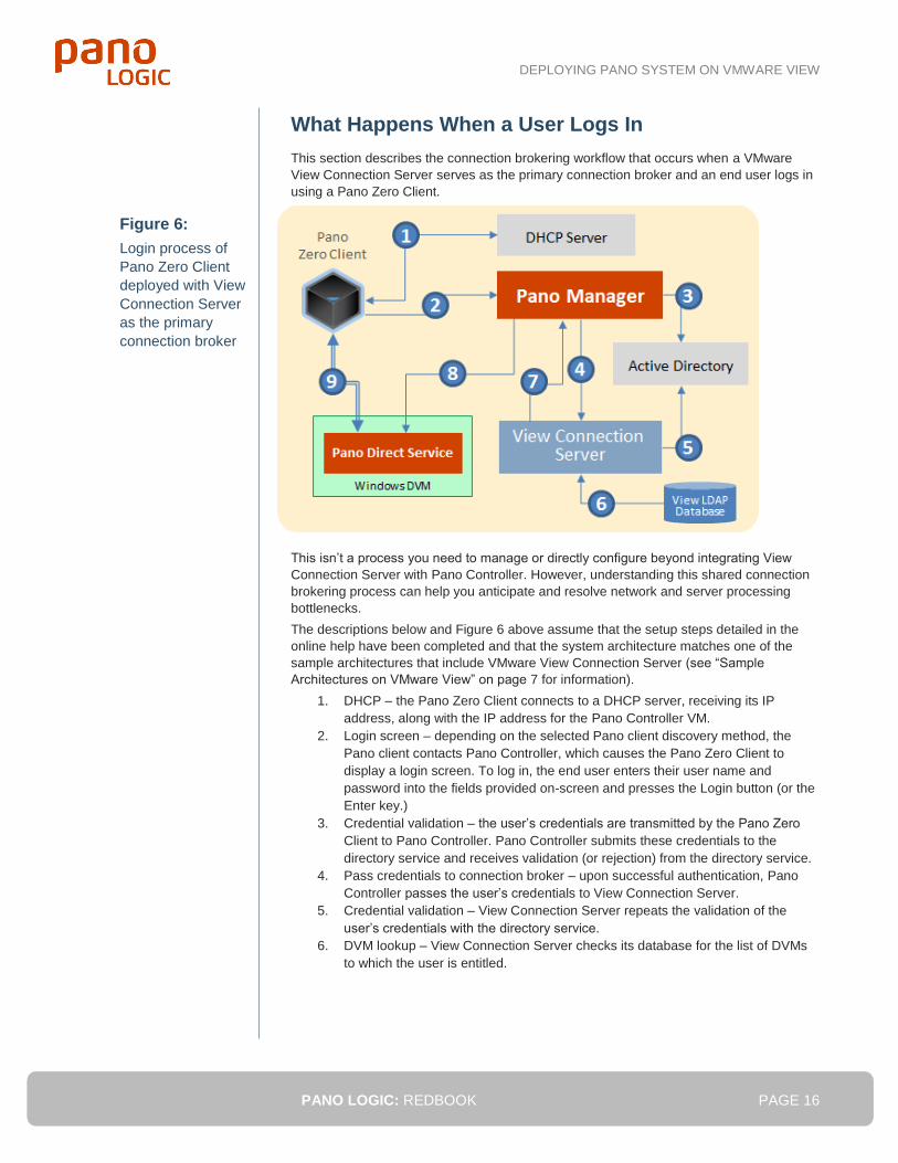
What Happens When a User Logs In
This section describes the connection brokering workflow that occurs when a VMware
View Connection Server serves as the primary connection broker and an end user logs in
using a Pano Zero Client.
This isn’t a process you need to manage or directly configure beyond integrating View
Connection Server with Pano Controller. However, understanding this shared connection
brokering process can help you anticipate and resolve network and server processing
bottlenecks.
The descriptions below and Figure 6 above assume that the setup steps detailed in the
online help have been completed and that the system architecture matches one of the
sample architectures that include VMware View Connection Server (see “Sample
Architectures on VMware View” on page 7 for information).
1. DHCP – the Pano Zero Client connects to a DHCP server, receiving its IP
address, along with the IP address for the Pano Controller VM.
2. Login screen – depending on the selected Pano client discovery method, the
Pano client contacts Pano Controller, which causes the Pano Zero Client to
display a login screen. To log in, the end user enters their user name and
password into the fields provided on-screen and presses the Login button (or the
Enter key.)
3. Credential validation – the user’s credentials are transmitted by the Pano Zero
Client to Pano Controller. Pano Controller submits these credentials to the
directory service and receives validation (or rejection) from the directory service.
4. Pass credentials to connection broker – upon successful authentication, Pano
Controller passes the user’s credentials to View Connection Server.
5. Credential validation – View Connection Server repeats the validation of the
user’s credentials with the directory service.
6. DVM lookup – View Connection Server checks its database for the list of DVMs
to which the user is entitled.
Figure 6:
Login process of
Pano Zero Client
deployed with View
Connection Server
as the primary
connection broker
DEPLOYING PANO SYSTEM ON VMWARE VIEW
PANO LOGIC: REDBOOK PAGE 17
7. Determine the specific desktop – View Connection Server returns a list of
Desktop Groups to Pano Controller. If the user is entitled to multiple Desktop
Groups, Pano Controller will automatically connect the user to the desktop most
recently accessed. (If instead of clicking the Login button, the user clicks the
Options button in Step (2), the user will be prompted to select the desired specific
desktop from a list of available desktops.)
8. Establish the connection – Pano Controller next checks on the status of the Pano
Direct Service running in the target DVM and ensures that it is ready to connect.
Once ready, Pano Controller facilitates the connection between the Pano Zero
Client and the Pano Direct Service on the appropriate DVM and steps aside.
9. The user is now connected to their desktop and all session traffic flows directly
from the Pano Direct Service to the Pano Zero Client.
Differences Running on VMware
This section describes the differences when running the Pano System on VMware View.
GENERAL DIFFERENCES ON VIEW
Pano Zero Clients and the current release of Pano System (4.5) have a number of
important differences and limitations when running on VMware View:
1. The Pano System does not use either the RDP or the Teradici PC-over-IP
protocols supported natively by VMware View. Instead, the Pano Direct Protocol
(PDP) is used to connect a Pano Zero Client to a DVM. In order to establish this
connection, the Pano Direct Service must be installed and running on the DVM.
Simply installing the VMware Tools in the DVM is not sufficient.
2. End users cannot access their DVMs from an RDP client such as Windows
Remote Desktop Connection if View Secure Authentication is enabled. For more
information, see “Configure VMware View Agent” in the online help.
3. You must be running in a vSphere 4.0 Update 1 (or later) environment. This is a
VMware requirement.
4. Pano Direct Service includes an XPDM display driver. This driver is incompatible
with the WDDM display drivers, including the ones installed by VMware Tools or
the VMware View Agent installers. You must uninstall the VMware SVGA 3D
(WDDM) driver and replace it with the VMware SVGA II (XPDM) driver. Please
refer to the online help for details instructions on installing the SVGA II display
driver.
LIMITATIONS WITH VIEW CONNECTION SERVER
You can run Pano Controller without integrating with View Connection Server as the
primary connection broker, using just the vSphere ESX/ESXi hypervisor and vCenter
Server from the View suite). However, there are limitations on what you can do when
integrated with View Connection Server. The main limitation is that only user-based
collections are supported, using a single special DVM Collection of the “VMware View”
type.
Table 8 on the next page lists limitations when deployed with and without View
Connection Server as the primary connection broker.
DEPLOYING PANO SYSTEM ON VMWARE VIEW
PANO LOGIC: REDBOOK PAGE 18
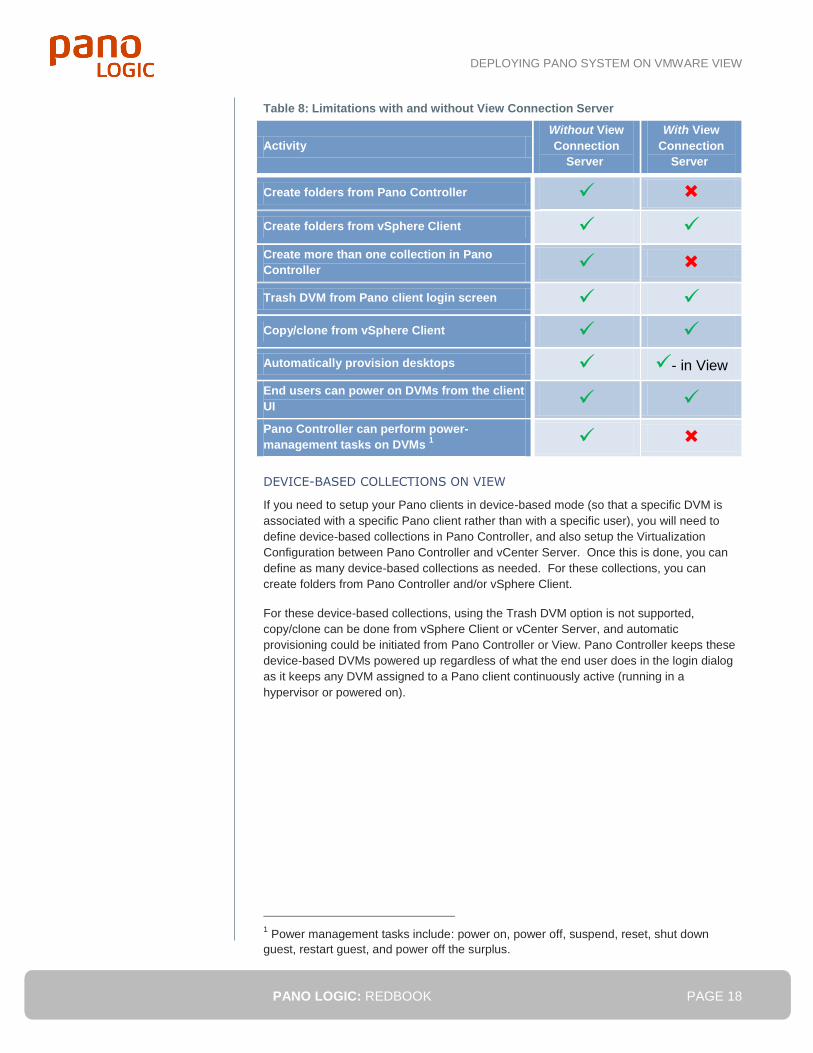
Table 8: Limitations with and without View Connection Server
Activity
Without View
Connection
Server
With View
Connection
Server
Create folders from Pano Controller
Create folders from vSphere Client
Create more than one collection in Pano
Controller
Trash DVM from Pano client login screen
Copy/clone from vSphere Client
Automatically provision desktops - in View End users can power on DVMs from the client
UI
Pano Controller can perform power-
management tasks on DVMs 1
DEVICE-BASED COLLECTIONS ON VIEW
If you need to setup your Pano clients in device-based mode (so that a specific DVM is
associated with a specific Pano client rather than with a specific user), you will need to
define device-based collections in Pano Controller, and also setup the Virtualization
Configuration between Pano Controller and vCenter Server. Once this is done, you can
define as many device-based collections as needed. For these collections, you can
create folders from Pano Controller and/or vSphere Client.
For these device-based collections, using the Trash DVM option is not supported,
copy/clone can be done from vSphere Client or vCenter Server, and automatic
provisioning could be initiated from Pano Controller or View. Pano Controller keeps these
device-based DVMs powered up regardless of what the end user does in the login dialog
as it keeps any DVM assigned to a Pano client continuously active (running in a
hypervisor or powered on).
1 Power management tasks include: power on, power off, suspend, reset, shut down
guest, restart guest, and power off the surplus.
DEPLOYING PANO SYSTEM ON VMWARE VIEW
PANO LOGIC: REDBOOK PAGE 19
More Information
Moe information can be found in these resources:
For detailed information on setting up and managing the Pano System, consult
the online help available at help.panologic.com and the support knowledgebase
in the Pano Logic Customer Center at support.panologic.com.
Specifications for the Pano System can be found in in the Pano System Data
Sheet at www.panologic.com/datasheet/panosystem.
Go to www.panologic.com/brochure-briefs for solution briefs on using VMware
View with the Pano System and for the Pano System on the VMware platform.
Information on VMware View and trial software downloads can be found on the
VMware website at www.vmware.com/products/view/
Detailed capacity planning advice for server, storage, and network hardware can
be found in the Infrastructure Sizing Redbook at
www.panologic.com/redbook/infrastructure.
General information on Pano deployment planning, platform choices, scalability
and redundancy options, best practices and sample architectures for 25-, 1,000-,
and 10,000-seat deployments can be found in the Deployment Architecture
Overview Redbook at www.panologic.com/redbook/overview.
Information on deployment planning for remote locations, such as branch offices,
distributed facilities and mobile workers, can be found in the Remote
Deployments Redbook at www.panologic.com/redbook/remote.
To obtain a Pano System Starter Kit, visit store.panologic.com, email
[email protected] or call 650-454-8940/877-677-PANO.
Pano Logic, Inc.
2000 Seaport Blvd, Suite 200
Redwood City, CA 94063
This document was released in November 2011 and is specific to the features and capabilities of
Pano System 5.0 [RB-PSVV-110211]
© Copyright 2011 Pano Logic, Inc.
Pano, Pano Logic, Pano Button, Pano Direct Protocol, and Pano Direct Technology are registered
trademarks of Pano Logic, Inc.
Pano Device, Pano Gateway, Pano Controller, Pano Remote, Pano Direct Service and Pano System
are trademarks of Pano Logic, Inc.