Embed Size (px)
Citation preview
1 Pantera Electronics Rev. 08/31/2016
Pantera Electronics Rocker Switch Installation Manual
PRELIMINARY
Dupli-Color METALCAST Part numbers: MC200, MC201 MC202, MC203 MC204, MC205
Finishing the Bezel [to achieve a anodized appearance with paint] 1. Remove the 4 screws and nylon washers that retain the housing to the internal electronics. (NOTE: Do not loose the nylon washers) 2. Polish to the desired surface finish. 3. Use a motorized buffing wheel with rouge. Several grades of rouge may be required. 4. Clean with lacquer thinner. 5. Use masking tape on all surfaces except the bezel contour edge. 6. Paint the bezel with DupliColor Metalcast paint. 7. Allow paint to dry thoroughly before removing the masking tape. 8. Assemble electronics into the housing, make sure to aligned the rocker through the opening in the housing. It can only fit one way. 9. Install the 4 screws and nylon washers then install the switch in the console panel. 10. Remove the backing from the label, note where the windows are and match to the bezel and insert the label.
2 Pantera Electronics Rev. 08/31/2016
General Installation for all types of Rocker Switches Disconnect the Battery by removing the negative (-) or ground cable from the battery terminal.
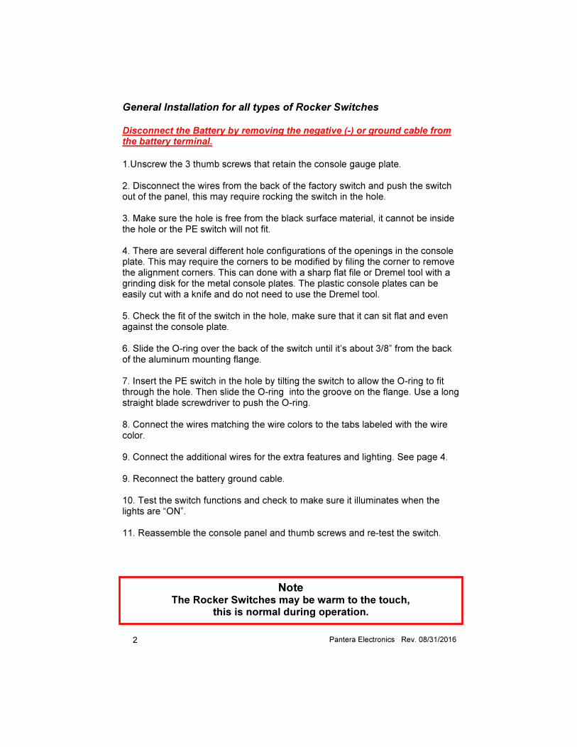
1.Unscrew the 3 thumb screws that retain the console gauge plate. 2. Disconnect the wires from the back of the factory switch and push the switch out of the panel, this may require rocking the switch in the hole. 3. Make sure the hole is free from the black surface material, it cannot be inside the hole or the PE switch will not fit. 4. There are several different hole configurations of the openings in the console plate. This may require the corners to be modified by filing the corner to remove the alignment corners. This can done with a sharp flat file or Dremel tool with a grinding disk for the metal console plates. The plastic console plates can be easily cut with a knife and do not need to use the Dremel tool. 5. Check the fit of the switch in the hole, make sure that it can sit flat and even against the console plate. 6. Slide the O-ring over the back of the switch until it’s about 3/8” from the back of the aluminum mounting flange. 7. Insert the PE switch in the hole by tilting the switch to allow the O-ring to fit through the hole. Then slide the O-ring into the groove on the flange. Use a long straight blade screwdriver to push the O-ring. 8. Connect the wires matching the wire colors to the tabs labeled with the wire color. 9. Connect the additional wires for the extra features and lighting. See page 4. 9. Reconnect the battery ground cable. 10. Test the switch functions and check to make sure it illuminates when the lights are “ON”. 11. Reassemble the console panel and thumb screws and re-test the switch.
Note
The Rocker Switches may be warm to the touch, this is normal during operation.
3 Pantera Electronics Rev. 08/31/2016
This is the alignment corner configuration that will need to be removed.
O-ring position for installation Approximately 3/8”
Tilt switch in both directions to pass the O-ring through.
4 Pantera Electronics Rev. 08/31/2016
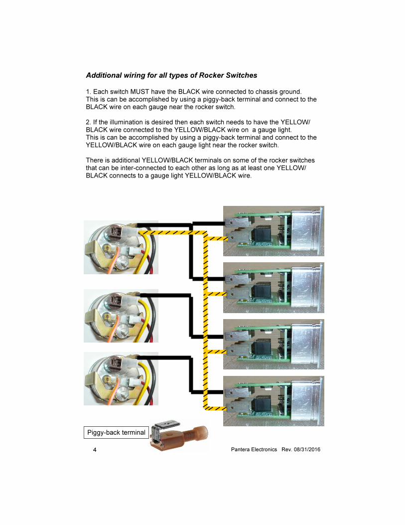
Additional wiring for all types of Rocker Switches 1. Each switch MUST have the BLACK wire connected to chassis ground. This is can be accomplished by using a piggy-back terminal and connect to the BLACK wire on each gauge near the rocker switch. 2. If the illumination is desired then each switch needs to have the YELLOW/BLACK wire connected to the YELLOW/BLACK wire on a gauge light. This is can be accomplished by using a piggy-back terminal and connect to the YELLOW/BLACK wire on each gauge light near the rocker switch. There is additional YELLOW/BLACK terminals on some of the rocker switches that can be inter-connected to each other as long as at least one YELLOW/BLACK connects to a gauge light YELLOW/BLACK wire.
Piggy-back terminal
5 Pantera Electronics Rev. 08/31/2016
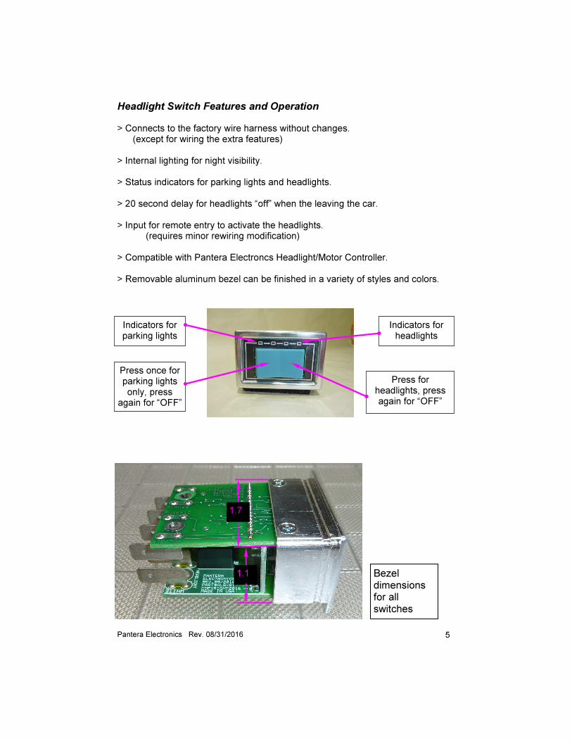
Indicators for parking lights
Press once for parking lights only, press
again for “OFF”
Press for headlights, press again for “OFF”
Indicators for headlights
Headlight Switch Features and Operation > Connects to the factory wire harness without changes. (except for wiring the extra features) > Internal lighting for night visibility. > Status indicators for parking lights and headlights. > 20 second delay for headlights “off” when the leaving the car. > Input for remote entry to activate the headlights. (requires minor rewiring modification) > Compatible with Pantera Electroncs Headlight/Motor Controller. > Removable aluminum bezel can be finished in a variety of styles and colors.
1.1
1.7
Bezel dimensions for all switches
6 Pantera Electronics Rev. 08/31/2016
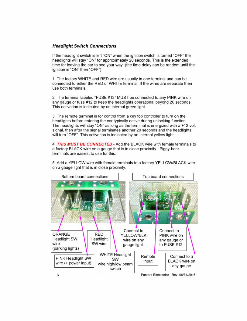
Bottom board connections Top board connections
ORANGE Headlight SW wire (parking lights)
PINK Headlight SW wire (+ power input)
RED Headlight SW wire
WHITE Headlight SW
wire high/low beam switch
Connect to YELLOW/BLK wire on any gauge light.
Connect to PINK wire on any gauge or to FUSE #12
Remote input
Connect to a BLACK wire on any gauge
Headlight Switch Connections If the headlight switch is left “ON” when the ignition switch is turned “OFF” the headlights will stay “ON” for approximately 20 seconds. This is the extended time for leaving the car to see your way. (the time delay can be random until the ignition is “ON” then “OFF”) 1. The factory WHITE and RED wire are usually in one terminal and can be connected to either the RED or WHITE terminal. If the wires are separate then use both terminals. 2. The terminal labeled “FUSE #12” MUST be connected to any PINK wire on any gauge or fuse #12 to keep the headlights operational beyond 20 seconds. This activation is indicated by an internal green light. 3. The remote terminal is for control from a key fob controller to turn on the headlights before entering the car typically active during unlocking function. The headlights will stay “ON” as long as the terminal is energized with a +12 volt signal, then after the signal terminates another 20 seconds and the headlights will turn “OFF”. This activation is indicated by an internal yellow light. 4. THIS MUST BE CONNECTED - Add the BLACK wire with female terminals to a factory BLACK wire on a gauge that is in close proximity. Piggy-back terminals are easiest to use for this. 5. Add a YELLOW wire with female terminals to a factory YELLOW/BLACK wire on a gauge light that is in close proximity.
7 Pantera Electronics Rev. 08/31/2016
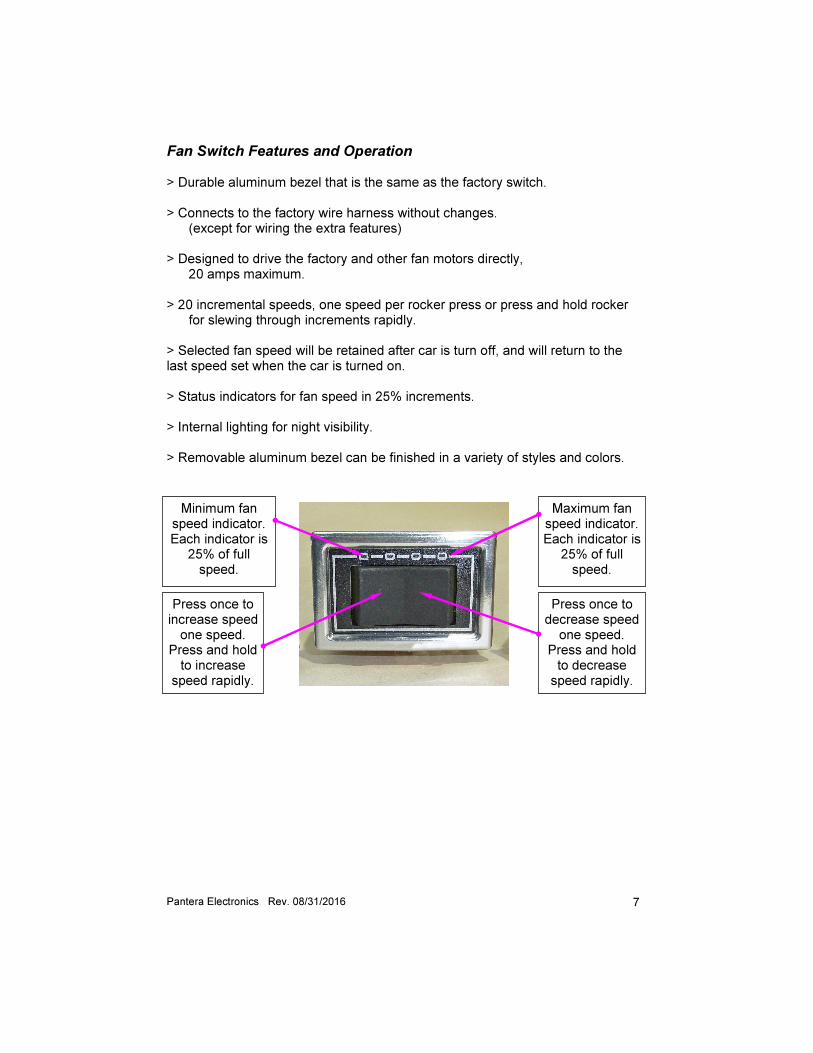
Fan Switch Features and Operation > Durable aluminum bezel that is the same as the factory switch. > Connects to the factory wire harness without changes. (except for wiring the extra features) > Designed to drive the factory and other fan motors directly, 20 amps maximum. > 20 incremental speeds, one speed per rocker press or press and hold rocker for slewing through increments rapidly. > Selected fan speed will be retained after car is turn off, and will return to the last speed set when the car is turned on. > Status indicators for fan speed in 25% increments. > Internal lighting for night visibility. > Removable aluminum bezel can be finished in a variety of styles and colors.
Minimum fan speed indicator. Each indicator is
25% of full speed.
Press once to increase speed one speed.
Press and hold to increase
speed rapidly.
Press once to decrease speed one speed.
Press and hold to decrease speed rapidly.
Maximum fan speed indicator. Each indicator is
25% of full speed.
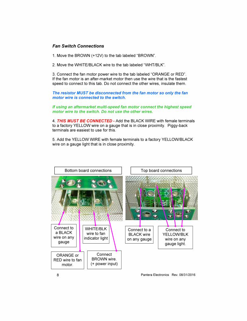
8 Pantera Electronics Rev. 08/31/2016
Bottom board connections Top board connections
Connect to a BLACK wire on any
gauge
ORANGE or RED wire to fan
motor.
WHITE/BLK wire to fan
indicator light
Connect BROWN wire. (+ power input)
Connect to YELLOW/BLK wire on any gauge light.
Connect to a BLACK wire on any gauge
Fan Switch Connections 1. Move the BROWN (+12V) to the tab labeled “BROWN”. 2. Move the WHITE/BLACK wire to the tab labeled “WHT/BLK”. 3. Connect the fan motor power wire to the tab labeled “ORANGE or RED”. If the fan motor is an after-market motor then use the wire that is the fastest speed to connect to this tab. Do not connect the other wires, insulate them. The resistor MUST be disconnected from the fan motor so only the fan motor wire is connected to the switch. If using an aftermarket multi-speed fan motor connect the highest speed motor wire to the switch. Do not use the other wires. 4. THIS MUST BE CONNECTED - Add the BLACK WIRE with female terminals to a factory YELLOW wire on a gauge that is in close proximity. Piggy-back terminals are easiest to use for this. 5. Add the YELLOW WIRE with female terminals to a factory YELLOW/BLACK wire on a gauge light that is in close proximity.
9 Pantera Electronics Rev. 08/31/2016
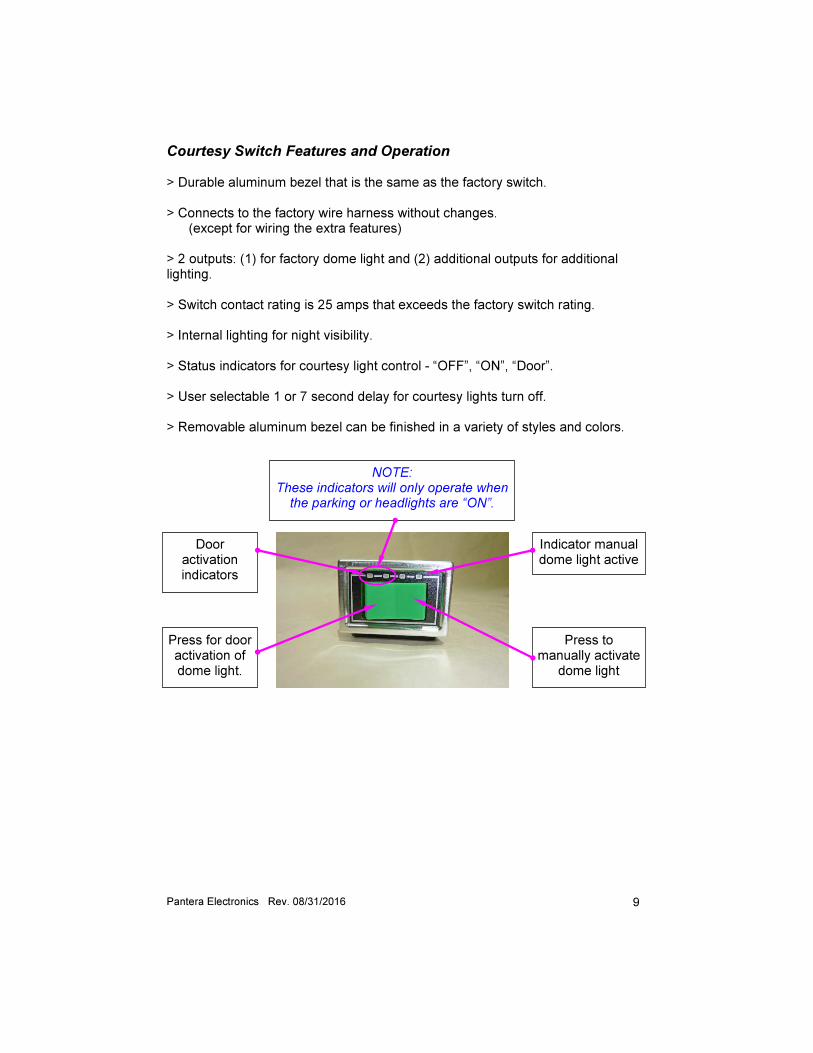
Courtesy Switch Features and Operation > Durable aluminum bezel that is the same as the factory switch. > Connects to the factory wire harness without changes. (except for wiring the extra features) > 2 outputs: (1) for factory dome light and (2) additional outputs for additional lighting. > Switch contact rating is 25 amps that exceeds the factory switch rating. > Internal lighting for night visibility. > Status indicators for courtesy light control - “OFF”, “ON”, “Door”. > User selectable 1 or 7 second delay for courtesy lights turn off. > Removable aluminum bezel can be finished in a variety of styles and colors.
Door activation indicators
Press for door activation of dome light.
Press to manually activate
dome light
Indicator manual dome light active
NOTE: These indicators will only operate when
the parking or headlights are “ON”.
10 Pantera Electronics Rev. 08/31/2016
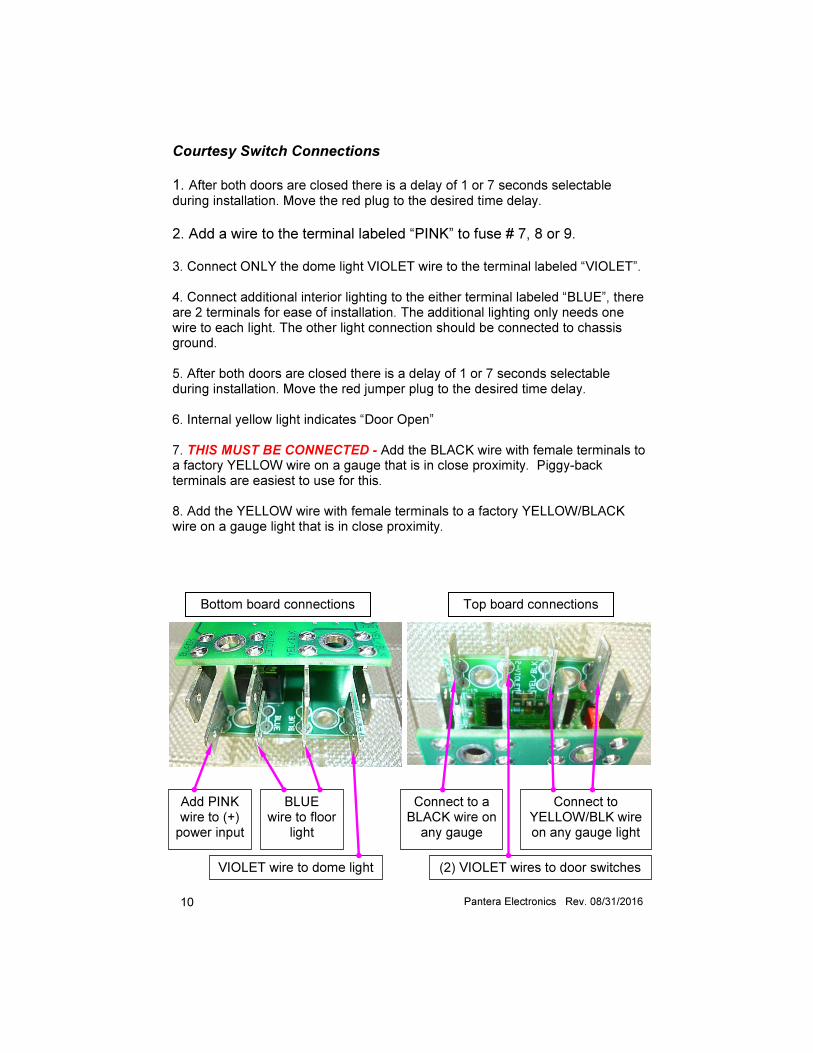
Bottom board connections Top board connections
Add PINK wire to (+) power input
VIOLET wire to dome light
BLUE wire to floor
light
(2) VIOLET wires to door switches
Connect to a BLACK wire on any gauge
Connect to YELLOW/BLK wire on any gauge light
Courtesy Switch Connections 1. After both doors are closed there is a delay of 1 or 7 seconds selectable during installation. Move the red plug to the desired time delay.
2. Add a wire to the terminal labeled “PINK” to fuse # 7, 8 or 9. 3. Connect ONLY the dome light VIOLET wire to the terminal labeled “VIOLET”. 4. Connect additional interior lighting to the either terminal labeled “BLUE”, there are 2 terminals for ease of installation. The additional lighting only needs one wire to each light. The other light connection should be connected to chassis ground. 5. After both doors are closed there is a delay of 1 or 7 seconds selectable during installation. Move the red jumper plug to the desired time delay. 6. Internal yellow light indicates “Door Open” 7. THIS MUST BE CONNECTED - Add the BLACK wire with female terminals to a factory YELLOW wire on a gauge that is in close proximity. Piggy-back terminals are easiest to use for this. 8. Add the YELLOW wire with female terminals to a factory YELLOW/BLACK wire on a gauge light that is in close proximity.
11 Pantera Electronics Rev. 08/31/2016
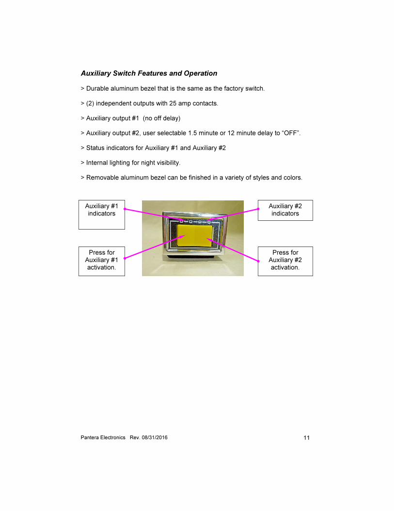
Auxiliary Switch Features and Operation > Durable aluminum bezel that is the same as the factory switch. > (2) independent outputs with 25 amp contacts. > Auxiliary output #1 (no off delay) > Auxiliary output #2, user selectable 1.5 minute or 12 minute delay to “OFF”. > Status indicators for Auxiliary #1 and Auxiliary #2 > Internal lighting for night visibility. > Removable aluminum bezel can be finished in a variety of styles and colors.
Auxiliary #1 indicators
Press for Auxiliary #1 activation.
Press for Auxiliary #2 activation.
Auxiliary #2 indicators
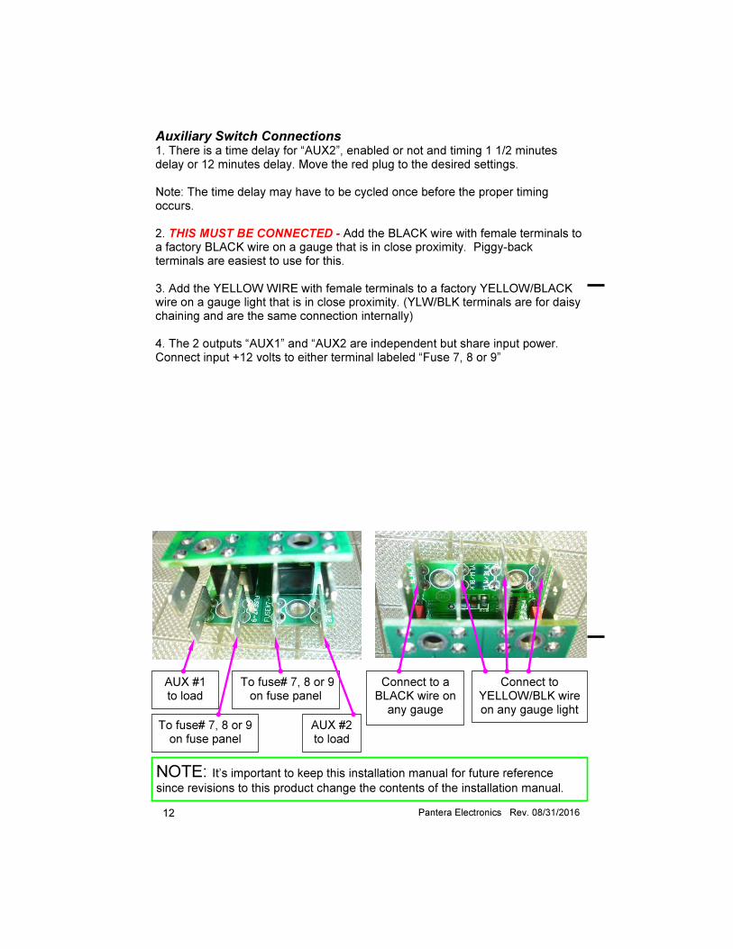
12 Pantera Electronics Rev. 08/31/2016
NOTE: It’s important to keep this installation manual for future reference
since revisions to this product change the contents of the installation manual.
AUX #1 to load
To fuse# 7, 8 or 9 on fuse panel
To fuse# 7, 8 or 9 on fuse panel
AUX #2 to load
Connect to YELLOW/BLK wire on any gauge light
Connect to a BLACK wire on any gauge
Auxiliary Switch Connections 1. There is a time delay for “AUX2”, enabled or not and timing 1 1/2 minutes delay or 12 minutes delay. Move the red plug to the desired settings. Note: The time delay may have to be cycled once before the proper timing occurs. 2. THIS MUST BE CONNECTED - Add the BLACK wire with female terminals to a factory BLACK wire on a gauge that is in close proximity. Piggy-back terminals are easiest to use for this. 3. Add the YELLOW WIRE with female terminals to a factory YELLOW/BLACK wire on a gauge light that is in close proximity. (YLW/BLK terminals are for daisy chaining and are the same connection internally) 4. The 2 outputs “AUX1” and “AUX2 are independent but share input power. Connect input +12 volts to either terminal labeled “Fuse 7, 8 or 9”