Embed Size (px)
Citation preview
8/4/2019 Paper-17_A Study On Diverse Communication Protocols
http://slidepdf.com/reader/full/paper-17a-study-on-diverse-communication-protocols 1/13
International Journal of Computational Intelligence and Information Security, August 2011 Vol. 2, No. 8
143
A STUDY ON DIVERSE COMMUNICATION PROTOCOLS
N.Rakesh1, Dr.S.K.Srivatsa
2
1Research Scholar, PRIST University,Tanjore, Tamil Nadu, India.
2Senior Professor, St. Joseph College of Engineering, Chennai, Tamil Nadu, India. [email protected], [email protected]
Abstract:
Still today data networks and voice (telephony) networks have always treaded their separate ways. With the start of the 21st
century they seem to have reached the new leash of communication technology.[2] We have entered into an era of
‘CONVERGENCE’(integration).[1] The boundary separating the two has narrowed to a thin red line. The thin red line- has
the inference makes, because the integration must be done carefully and intelligently.[1] As we know, VPN (Virtual Private
Network) which is a technology that provides safe communication for data as its transmission through apprehensive areas of
information technology. With productive development of the Internet, businesses, today implement VPN tunnels using myriad
protocols that guarantee data protection and security between multiple sites connected using public telecommunication
network. It provides less-cost substitute to telephone leased line for having communication between sites. ‘VoIP’ is a tool that
would greatly hasten this process.[5] Voice over IP (VoIP) uses the Internet Protocol (IP) to transmit voice as packets over anIP network. So VoIP can be achieved on any data network that uses IP, like Internet, Intranets and Local Area Networks
(LAN). Here the voice signal is digitized, compressed and converted to IP packets and then transmitted over the IP
network.[1] As the advents changed, various communication protocols were invented and accordingly application of it started
as per the needs. Here in this paper we tried to give a brief idea about such different communication protocols.
Keywords: - H.323, IP, MGCP, MPLS, RTP, RTCP, RSVP, SAP, SCP, SDP, VoIP, VPN.
1. Introduction:
When we take human beings, apparently humans talk, we banish air from the lungs and move the lips, tongue, and larynx to
generate sound waves. The sound waves pass through the air and reach the inner ear of the other party, stimulating the sense
of hearing aspect. There is a limitation, however, in the distance and energy level of the sound wave. The distance at which a
sound can be heard depends upon the intensity (decibels) and volume (amplitude) of the sound. For an instance walkie-talkie,a microphone, and a residential telephone are all examples of devices that can be used to carry and amplify the sound so it can
be heard over a distance. Mainly, these and other electronic devices convert voice activity into electrical current or voltage,
helping to overcome the problems associated with the nature of the sound wave. The most common example of a
telecommunications device is telephone at home. When we plug an ordinary analog phone into the phone jack installed by the
telephone service provider, we are then able to place phone calls. As when distinct protocols came into picture, later usage
was efficient, feasible and low cost effective services were provided.[3], [33], [56]-[62].
2. About Telephone service today: Nowadays private branch exchanges (PBXs) provide the service that the operator
performed in the early telephone company. A PBX is a small telephone switch owned by a company or organization. Withouta PBX, a company would need to lease one telephone line for every employee who has a telephone. With a PBX, the company
only needs to lease as many lines from the telephone company as the maximum number of employees that will be making
outside calls at one time.[1]-[3]
2.1. LOOPS, LINES, TRUNKS AND PBX TRUNKS: The key components of a telecommunications network are hasfollows:-
Fig 1 Loops, Lines & Trunks
a. The loops: A loop is literally the physical pair of wires that connects a telephone directly to a CO’s switch or a PBX.
It consists of a two- or four-wire pair that is twisted to minimize the electromagnetic radiation created by the currentflowing through the wire. When a phone handset is off hook, the current flow is detected by a current detector in the
CO. When a phone is on hook, the loop is open and no current flows.
8/4/2019 Paper-17_A Study On Diverse Communication Protocols
http://slidepdf.com/reader/full/paper-17a-study-on-diverse-communication-protocols 2/13
International Journal of Computational Intelligence and Information Security, August 2011 Vol. 2, No. 8
144
b. The lines: The terms line and loop often get confused. A line is a communications path between a customer's
telephone and a telephone switch, such as a PBX or a CO switch. Although a line is typically based on a physical
loop, it is not necessarily a physical connection. A line could be a logical connection, such as a channel on a
multiplex system. A leased line is a dedicated line reserved by a carrier for the private use of a leasing customer.
c. The trunks: Whereas a line connects the telephone with the switch, a trunk is a shared communications channel that
connects switches and has the capacity to carry a phone call. A trunk is assigned to connections on a call-by-callbasis. Over time, the trunk is shared by all the users who call between this pair of switches.
d. The PBX trunks: In a business using a PBX, every employee's telephone line is connected to the PBX. When an
employee picks up the receiver and dials the outside access code (instance 9), the PBX connects the employee to an
outside line—the Public Switched Telephone Network, or PSTN. PBXs combine with trunks between them.
[1],[2],[3]-[32].
3. Supporting Communication Protocol: - Here, we jot down some of the communication protocols, SIP (Session
Initiation Protocol) works in conjunction with RSVP (Resource Reservation Protocol), RTP/RTCP (Real-time Transport
Protocol), RTSP (Real-time Streaming Protocol), SAP (Session Announcement Protocol) and SDP (Session Description
Protocol). RTP/RTCP is used for transporting real time data, RSVP for reserving resources, RTSP for controlled delivery of
streams, SAP for advertising multimedia sessions and SDP for describing multimedia sessions. H.323 too works in
conjunction with RTP and RTCP (Real-time Control Protocol). The present day voice gateways usually compose of two parts:the signaling gateway and the media gateway. The signaling gateway communicates with the media gateway using MGCP(Media Gateway Access Protocol). MGCP can interoperate with both SIP and H.323.[3],[14],[20],[21],[24],28],[29],[30]-[31].
4. Media Gateway Control Protocol (MGCP): It is a protocol that defines communication between call control
elements (Call Agents) and telephony gateways. It is a master/slave protocol, where the gateways are expected to execute
commands sent by the Call Agents. Call Agents are also known as Media Gateway Controllers. MGCP is a control protocol,
allowing a central coordinator to monitor events in IP phones and gateways and instructs them to send media to specific
addresses. [3]The main emphasis of MGCP is simplicity and reliability and it allows programming difficulties to be concentrated in Call
Agents, so it will enable service providers to develop reliable and cheap local access systems.
a. The Endpoints and Connections: Endpoints are the sources or sinks of data. An example could be an interface on a
gateway that terminates a trunk connected to a PSTN switch. Connections may be either point-to-point or multipoint.
A connection is either an association between two endpoints (point-to-point) or it is an association between multipleendpoints (multipoint). Once the association is established, data transfer can take place. Connections can beestablished over a number of bearer networks i.e. TCP/IP, ATM etc.
b. The Events and Signals: A call agent may ask to be notified about certain events occurring in an endpoint, such as
off-hook, on-hook, dialed digits, and may request that a certain signal be applied to an endpoint such as dial-tone,
busy tone or ringing. Events and signals are grouped in packages that are supported by a particular type of endpoint
e.g., one package may support a certain group of events and signals for analog access lines.[3]-[66].
4.1. Establishment of connections:-The connections are created on the call agent at each endpoint that will be
involved in the call. When the two endpoints are located on gateways that are managed by the same call agent, the creation is
done through the following three steps:
• The Call Agent asks the first gateway to create a connection on the first endpoint. The response sent by the gateway
includes a session description that contains pertinent information required by third parties to be able to send packets
to the new connection that has been created.• The Call Agent then sends the session description of the first gateway to the second gateway and asks it to create a
connection on the second endpoint. The second gateway responds by sending its own session description.
• The Call Agent uses a modify connection command to provide this second session description to the first endpoint. Now
communication can occur in both directions.
• When the two endpoints are located on gateways that are managed by the different call agents, these two call agents
shall exchange information through a call agent to call agent signaling protocol, in order to synchronize the creationof the connection on the two endpoints.[3]-[66].
4.2. The MGCP commands: The MGCP implements the media gateway control interface as a set of transactions. The
transactions are composed of a command and a mandatory response. There are 8 types of commands:
• The CreateConnection: The CreateConnection command is used to attach an endpoint to a specific IP address and
port. To create a connection, a CreateConnection request is required for the remote endpoint also. If the request issuccessfully acknowledged by the gateway, then a ConnectionId is returned that uniquely identifies the connection.
• The ModifyConnection: This command is used by the call agent to modify the parameters of an active connection. The
ConnectionId is passed to identify the connection.

8/4/2019 Paper-17_A Study On Diverse Communication Protocols
http://slidepdf.com/reader/full/paper-17a-study-on-diverse-communication-protocols 3/13
International Journal of Computational Intelligence and Information Security, August 2011 Vol. 2, No. 8
145
• The DeleteConnection: This command is used by either the call agent or the gateway to delete an existing connection.
The response includes a list of parameters about the status of the connection.
• The NotificationRequest: If a call agent wants to be informed about the occurrence of specified events in an endpoint,
then it can send this request to the gateway. Events could be: off hook transition, flash-hook, continuity tone
detection, etc. A notification may be requested for a continuity tone detection event in a gateway.
• The Notify: The response to the Notification Request is sent via the Notify command by the gateway. The notify
command includes a list of events that the gateway observed.• The Audit Endpoint: This command is used by the call agent to get details about the status of an endpoint/several
endpoints and the response from the gateway contains the requested information.
• The Audit Connection: To obtain information for a specific connection of an endpoint, the call agent uses this
command. The connection is identified by the ConnectionId and the response from the gateway contains the
requested information.• The Restart in Progress: This command is used by the gateway to indicate that an endpoint or a bunch of endpoints
have been taken in/out of service. It also includes a parameter that indicates the type of restart (graceful restart/
forced restart/delayed restart).[3],[63]-[66].
5. Real-time Transport Protocol (RTP) & Real-time Transport Control Protocol (RTCP): Professed
real-time delivery of traffic requires little in the way of transport protocol. Meticulously, real-time traffic that is sent over
more than slight distances is not retransmit table. In reality, a number of facets of an end-to-end protocol need to be re-
designed or refined including:[3]a. The Separate Flows for each Media Stream: With packet multimedia data there is no need for the different media
comprising a session to be carried in the same packets. In fact it simplifies receivers if different media streams are
carried in separate flows (i.e., separate transport ports and/or separate multicast groups). This also allows the
different media to be given different quality of service.
b. The Receiver Adaptation: Best-effort traffic is delayed by queues in routers between the sender and the receivers.
Even reserved priority traffic may see small transient queues in routers, and so packets comprising a flow will be
delayed for different times. Such delay variance is known as jitter. Real-time applications such as audio and video
need to be able to buffer real-time data at the receiver for sufficient time to remove the jitter added by the network
and recover the original timing relationships between the media data. In order to know how long to buffer, each
packet must carry a timestamp which gives the time at the sender when the data was captured.c. The Synchronization: As audio and video flows will receive differing jitter and possibly differing quality of service,
audio and video that were captured at the same time at the sender may not arrive at the receiver at the same time. At
the receiver, each flow will need a play-out buffer to remove network jitter. [20]-[22].
5.1. The Supporting of RTP: It supports the transfer of real-time media (audio and video) over packet switched
networks. The transport protocol must allow the receiver to detect any losses in packets and also provide timing informationso that the receiver can correctly compensate for delay jitter. The RTP header contains information that assist the receiver to
reconstruct the media and also contains information specifying how the codec bit streams are broken up into packets. RTP
does not reserve resources in the network but instead it provides information so that the receiver can recover in the presence of
loss and jitter. The functions provided by RTP include:
a. The Sequencing: The sequence number in the RTP packet is used for detecting lost packets
b. The Payload Identification: In the Internet, it is often required to change the encoding of the media dynamically to
adjust to changing bandwidth availability. To provide this functionality, a payload identifier is included in each RTP
packet to describe the encoding of the media
c. The Frame Indication: Video and audio are sent in logical units called frames. To indicate the beginning and end of
the frame, a frame marker bit has been provided
d. The Source Identification: In a multicast session, we have many participants. So an identifier is required to determine
the originator of the frame. For this Synchronization Source (SSRC) identifier has been provided.
e. The Intramedia Synchronization: To compensate for the different delay jitter for packets within the same stream,
RTP provides timestamps, which are needed by the play-out buffers. [13].
5.2. The Convergence of RTCP with RTP: It is a control protocol and works in conjunction with RTP. In a RTP
session, participants periodically send RTCP packets to obtain useful information about QoS etc. The additional services that
RTCP provides to the participants are:a. The QoS feedback: RTCP is used to report the quality of service. The information provided includes number of lost
packets, Round Trip Time, jitter and this information is used by the sources to adjust their data rate.
b. The Session Control: By the use of the BYE packet, RTCP allows participants to indicate that they are leaving a
sessionc. The Identification: Information such as email address, name and phone number are included in the RTCP packets so
that all the users can know the identities of the other users for that session.
8/4/2019 Paper-17_A Study On Diverse Communication Protocols
http://slidepdf.com/reader/full/paper-17a-study-on-diverse-communication-protocols 4/13
International Journal of Computational Intelligence and Information Security, August 2011 Vol. 2, No. 8
146
d. The Intermedia Synchronization: Although video and audio are normally sent over different streams, we need to
synchronize them at the receiver so that they play together. RTCP provides the information that is required for
synchronizing the streams. [28]-[29].
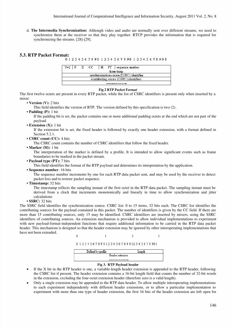
5.3. RTP Packet Format:
Fig 2 RTP Packet Format
The first twelve octets are present in every RTP packet, while the list of CSRC identifiers is present only when inserted by a
mixer.
• Version (V): 2 bitsThis field identifies the version of RTP. The version defined by this specification is two (2).
• Padding (P): 1 bit
If the padding bit is set, the packet contains one or more additional padding octets at the end which are not part of thepayload.
• Extension (X): 1 bitIf the extension bit is set, the fixed header is followed by exactly one header extension, with a format defined in
Section 5.2.1.
• CSRC count (CC): 4 bits
The CSRC count contains the number of CSRC identifiers that follow the fixed header.
• Marker (M): 1 bit
The interpretation of the marker is defined by a profile. It is intended to allow significant events such as frame
boundaries to be marked in the packet stream.
• Payload type (PT): 7 bits
This field identifies the format of the RTP payload and determines its interpretation by the application.
• Sequence number: 16 bits
The sequence number increments by one for each RTP data packet sent, and may be used by the receiver to detectpacket loss and to restore packet sequence.
• Timestamp: 32 bits
The timestamp reflects the sampling instant of the first octet in the RTP data packet. The sampling instant must be
derived from a clock that increments monotonically and linearly in time to allow synchronization and jitter
calculations
• SSRC: 32 bitsThe SSRC field identifies the synchronization source. CSRC list: 0 to 15 items, 32 bits each. The CSRC list identifies the
contributing sources for the payload contained in this packet. The number of identifiers is given by the CC field. If there are
more than 15 contributing sources, only 15 may be identified. CSRC identifiers are inserted by mixers, using the SSRC
identifiers of contributing sources. An extension mechanism is provided to allow individual implementations to experiment
with new payload-format-independent functions that require additional information to be carried in the RTP data packet
header. This mechanism is designed so that the header extension may be ignored by other interoperating implementations that
have not been extended.
Fig 3. RTP Payload header
• If the X bit in the RTP header is one, a variable-length header extension is appended to the RTP header, followingthe CSRC list if present. The header extension contains a 16-bit length field that counts the number of 32-bit words
in the extension, excluding the four-octet extension header (therefore zero is a valid length).
• Only a single extension may be appended to the RTP data header. To allow multiple interoperating implementations
to each experiment independently with different header extensions, or to allow a particular implementation toexperiment with more than one type of header extension, the first 16 bits of the header extension are left open for
8/4/2019 Paper-17_A Study On Diverse Communication Protocols
http://slidepdf.com/reader/full/paper-17a-study-on-diverse-communication-protocols 5/13
International Journal of Computational Intelligence and Information Security, August 2011 Vol. 2, No. 8
147
distinguishing identifiers or parameters. The format of these 16 bits is to be defined by the profile specification under
which the implementations are operating.[3],[13],[28]-[29].
5.4.RTP Header Compression: Here the amalgamation of the IP, UDP and RTP control information adds up to a
significant overhead for small media samples, particularly over low speed links, commonly in use by the domestic and small
office user dialing up their Internet Service Provider at a few tens of kilobits per second.
• An IP Datagram has a 20 byte header, while the UDP header is 8 bytes (source and destination ports, plus length andchecksum field).
• The RTP header adds 12 bytes to this, making a total of 40 bytes of control for a single sample, in some cases as little
as 20ms worth of 8KHzspeech. [21]
5.5. The RTP Multiplexing: We know well, that multiplexers culminate various signals in a single channel. There are a
number of circumstances in which one might wish to carry multiple media flows within a single RTP data payload between
two points. The two most important cases are:
• IP paths between Internet Telephony Gateways
• Special hardware devices such as CODECs with non-negotiable multiplexed media.
There are at least two ways to multiplex data in RTP packets.
a. One could (e,g. in the telephony case) assume that all the samples have the same payload types, and are just offset in
different end-to-end flows. Here we need a mapping table in the gateways, which indicates the offset for eachpayload type and a list of the flows in each packet. In RTP, multiplexing is provided by the destination transport
address (network address and port number), which defines an RTP session.
b. The second approach is to adapt the ideas concerning RTP header compression and to allow for multiple compressed
headers within a single RTP packet, one for each of the samples. This latter approach would not use precisely the
same compression algorithm, since the fields differ for different reasons, but would permit multiple different media
to be efficiently encapsulated in a single packet. This might address both types of application of RTP multiplexingmore effectively. [3]-[13].
5.6. The RTCP Packet Format: RTCP is the Real-time Transport Control Protocol, which may be used as a frivolous
companion to RTP to convey a number of statistics and other information about an RTP flow between recipients and senders.
This specification defines several RTCP packet types to carry a variety of control information:
• SR: The Sender report for transmission and reception statistics from participants that are active senders
• RR: The Receiver report for reception statistics from participants that are not active senders• SDES: The Source description items, including CNAME (Canonical Identifier), NAME: User name, EMAIL:
Electronic mail address, PHONE: Phone number, LOC: Geographic user location, TOOL: Application or tool name,
NOTE: Notice/status, PRIV: Private extensions
• BYE: It indicates end of participation and a reason for leaving
• APP: The application specific functions.
Each RTCP packet begins with a fixed part similar to that of RTP data packets, followed by structured elements that may be
of variable length according to the packet type but always end on a 32-bit boundary. [13],[20]-[22].
6. The Real-time Streaming Protocol (RTSP): If our audio and video streams come to us over a network, and are
reposited in the computer's memory, then at the very least we should expect to be able to control the streams in the same
fashion as we control traditional channel. We should be able to start the program playing, suspend the stream if we wish, skip
further along the stream to locate the interesting bits, and slow or speed up the program as required.[69]
• Since the medium for the stream is a network connected to a computer, building the controls is simply a matter of designing a program and the associated techniques for talking to other programs. The stream is generated by a node
on the network, which is called a media server, and is sent as a stream of packets over the network to the receiver(s),
which appropriately process and pass the data up to the application.
• Here we have two feasible ways of controlling the media streams - we could send messages back over the network tothe source of the stream to ask the source to play, stop, pause etc., or we could allow the stream to come to us, and
simply manipulate the media in memory, keeping control within the receiving computer. The Real-Time Streaming
Protocol (RTSP) establishes and controls either a single or several time-synchronized streams of continuous media
such as audio or video. RTSP acts a ``network remote control'' for multimedia servers.[40],[41]-[69].
6.1. The RTSP URLs: The Multimedia presentations are identified by URLs, using a protocol scheme of RTSP. The
hostname is the server containing the presentation; whilst the port indicates which port the RTSP control requests should besent to. Presentations may consist of one or more separate streams. The presentation URL provides a means of identifying and
controlling the whole presentation rather than coordinating the control of each individual steam.
8/4/2019 Paper-17_A Study On Diverse Communication Protocols
http://slidepdf.com/reader/full/paper-17a-study-on-diverse-communication-protocols 6/13
International Journal of Computational Intelligence and Information Security, August 2011 Vol. 2, No. 8
148
6.2. The RTSP Messages: RTSP add a number of new requests to the existing HTTP requests. These are:
• Describe: It causes a server to return a description of the protocol using the Session Description Protocol.
• Announce: It allows a client or server to register a description of a presentation.
• Options: It causes a server to return the list of supported methods.
• Setup: It causes a server to allocate resources for a stream and starts an RTSP session. This manipulates state.
• Play: It starts data transmission on a stream allocated by SETUP. This manipulates state.
• Record: It starts a server recording an allocated stream. This manipulates state.• Pause: It temporarily halts transmission of a stream without freeing server resources. This manipulates state.
• Teardown: It frees resources associate with a stream, so that the RTSP session ceases to exist. This manipulates state.
• get_parameter and set_parameter: The placeholder method to allow parameters of presentations and sessions to be
manipulated.
• Redirect: It causes a client to go to another server for parts of a presentation. [3],[53],[54]-[69].
6.3.The RTSP Sessions: The pivotal concept in RTSP is the conception of a session. RTSP works by first requesting a
presentation to be started by a server, receiving in return a session identifier which it then uses in all subsequent controls.
Eventually, the client can request the teardown of session, which releases the associated resources. The session identifier
represents the shared state between the client and server. If the state is lost, for example through one of the machines being
rebooted, then the protocol relies on the transport of the media stopping automatically. [13],[52]-[69].
6.4. The RTSP Operation: The media streams are referenced through specification of their times, either relative to the
start time of the presentation, or in real time. RTSP allows the use of the standard time codes used in industry such as SMTPE
or Normal Play Time, or by specifying an absolute time for presentations in real-time. To exhibit a presentation, the client
software first requires the RTSP URL of the presentation. If it has this URL, it can then display the presentation by following
these steps.
a) The client first requests the description of the presentation using the DESCRIBE method. This supplies details of the media
streams, so that the client can start the appropriate media applications.
b) The client then requests that the session is SETUP, receiving a session identifier in return. The server would allocate state,
such as the sockets through which the media will be sent, plus any reservations for bandwidth.
c) The client requests that the media streams of the session are played, by specifying the URL and the session identifier, and a
time range to start and finish playing at.
d) At any point they may PAUSE the presentation, and continue form any other point in the presentation by using specifying a
new range in the PLAY request.e) When the client has completed, the client issues a TEARDOWN request to destroy the session, and deallocate any
resources.[41]-[50].
7. The Session Description Protocol (SDP): A session explanation expressed in SDP is a short structured textual
description of the name and purpose of the session, and the media, protocols, codec formats, timing and transport information
that are required to decide whether a session is likely to be of interest and to know how to start media tools to participate inthe session. [3]-[69].
7.1. The Timing Information: The sessions may either be restricted or unbounded in time. Whether or not they are
bounded, they may be only active at specific times. It can convey an arbitrary list of start and stop times bounding the session.
For each bound, repeat times can be specified. This timing information is globally consistent. Modifiers can be specified to
uniquely apply offsets.[14]-[25].
7.2. The Media Descriptions: A session description is composed of general information that applies to the wholesession (such as the timing) followed by sections that are specific to each medium. For each medium SDP includes the type of
media (video, audio, etc), the transport protocol (RTP/UDP/IP etc), the format of the media (H.261 video, MPEG video, etc),
and media or codec specific attributes. [14]-[69].
7.3.SDP Syntax: An SDP session description consists of a number of lines of text of the form:
<type>=<value>
<type> is always exactly one character and is case-significant.
<value> is a structured text string whose format depends on <type>. In general <value> is either a number of fields delimited
by a single space character or a free format string.
The session description consists of a session-level description (details that apply to the whole session and all media streams)
and optionally several media-level descriptions (details that apply only to a single media stream). The session-level part starts
with a `v=' line and continues to the first media-level section. The media description starts with an `m=' line and continues to
the next media description or to the end of the whole session description. In general, session-level values are the default for allmedia unless overridden by an equivalent media-level value.
8/4/2019 Paper-17_A Study On Diverse Communication Protocols
http://slidepdf.com/reader/full/paper-17a-study-on-diverse-communication-protocols 7/13
International Journal of Computational Intelligence and Information Security, August 2011 Vol. 2, No. 8
149
Fig 4 SDP Example
The individual fields have the following meanings, and must be in this order, with ``*'' indicating an optional field:
v= The Protocol Version
o= The Owner/Creator and Session Identifier
s= The Session Name
i=* Session Information
u=* URI of description
e=* Email Address
p=* The Phone Numberc=* Connection Information
b=* Bandwidth Information
One or more time descriptions
z=* Time Zone Adjustments
k=* About Encryption Key
a=* zero or more Session AttributesZero or more media descriptions
Each time description consists of a ``t='' field, optionally followed by one or more ``r='' fields.
t= Time the Session is Active
r=* zero or more Repeat Times
Each media description consists of a ``m'' field, with other optional fields providing additional information:
m= The Media Name and Transport Address
i=* Media Titlec=* About Connection Information
b=* About Bandwidth Information
k=* Encryption Key
a=* zero or more Media Attributes
The connection (`c=') and attribute (`a=') information in the session-level section applies to all the media of that session unless
overridden by connection information or an attribute of the same name in the media description.[1],[3],[20],[26]-[27].
8. The Session Announcement Protocol (SAP): It gives a promotional view; the protocol is used for advertising
the multicast conferences and other multicast sessions. A SAP announcement is multicast with the same scope as the session it
is announcing, ensuring that the recipients of the announcement can also be potential recipients of the session being
advertised. If a session uses addresses in multiple administrative scope ranges, it is necessary for the announcer to send
identical copies of the announcement to each administrative scope range.[51],[58],[61]-[70].
• The Multiple announcers may announce a single session, as an aid to robustness in the face of packet loss and failure
of one or more announcers. The time period between repetitions of an announcement is chosen such that the totalbandwidth used by all announcements on a single SAP group remains below a preconfigured limit. Each announcer
is expected to listen to other announcements in order to determine the total number of sessions being announced on a
particular group.
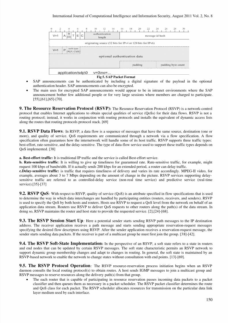
8.1. The SAP Packet Format: The below for IPv4 figure is shown. The Message Type (T) field indicates whether this
packet announces a session, or deletes an announcement. One bit (E) indicates whether or not the payload is encrypted and
one bit (C) indicates whether or not the payload is compressed.
• The combination of message ID hash and original source is supposed to provide a unique announcement ID that can
be used to identify this particular version of this particular session.
8/4/2019 Paper-17_A Study On Diverse Communication Protocols
http://slidepdf.com/reader/full/paper-17a-study-on-diverse-communication-protocols 8/13
International Journal of Computational Intelligence and Information Security, August 2011 Vol. 2, No. 8
150
Fig 5. SAP Packet Format
• SAP announcements can be authenticated by including a digital signature of the payload in the optional
authentication header. SAP announcements can also be encrypted.
• The main uses for encrypted SAP announcements would appear to be in intranet environments where the SAP
announcement bother few additional people or for very large sessions where members are charged to participate.
[55],[61],[65]-[70].
9. The Resource Reservation Protocol (RSVP): The Resource Reservation Protocol (RSVP) is a network-control
protocol that enables Internet applications to obtain special qualities of service (QoSs) for their data flows. RSVP is not arouting protocol; instead, it works in conjunction with routing protocols and installs the equivalent of dynamic access lists
along the routes that routing protocols protocol stack. [69]
9.1. RSVP Data Flows: In RSVP, a data flow is a sequence of messages that have the same source, destination (one or
more), and quality of service. QoS requirements are communicated through a network via a flow specification. A flow
specification often guarantees how the internetwork will handle some of its host traffic. RSVP supports three traffic types:
best-effort, rate-sensitive, and the delay-sensitive. The type of data-flow service used to support these traffic types depends on
QoS implemented. [38]
a. Best-effort traffic: It is traditional IP traffic and the service is called Best-effort service.
b. Rate-sensitive traffic: It is willing to give up timeliness for guaranteed rate. Rate-sensitive traffic, for example, might
request 100 kbps of bandwidth. If it actually sends 200 kbps for an extended period, a router can delay traffic.
c.Delay-sensitive traffic: is traffic that requires timeliness of delivery and varies its rate accordingly. MPEG-II video, forexample, averages about 3 to 7 Mbps depending on the amount of change in the picture. RSVP services supporting delay-
sensitive traffic are referred to as controlled-delay service (non-real time service) and predictive service (real-time
service).[35]-[37]
9.2. RSVP QoS: With respect to RSVP, quality of service (QoS) is an attribute specified in flow specifications that is used
to determine the way in which data interchanges are handled by participating entities (routers, receivers, and senders). RSVP
is used to specify the QoS by both hosts and routers. Hosts use RSVP to request a QoS level from the network on behalf of anapplication data stream. Routers use RSVP to deliver QoS requests to other routers along the path(s) of the data stream. In
doing so, RSVP maintains the router and host state to provide the requested service. [2],[24]-[68].
9.3. The RSVP Session Start Up: Here a potential sender starts sending RSVP path messages to the IP destination
address. The receiver application receives a path message and starts sending appropriate reservation-request messagesspecifying the desired flow descriptors using RSVP. After the sender application receives a reservation-request message, the
sender starts sending data packets. If the receiver is part of a multicast group he must first join the group. [38]-[42].
9.4. The RSVP Soft-State Implementation: In the perspective of an RSVP, a soft state refers to a state in routers
and end nodes that can be updated by certain RSVP messages. The soft state characteristic permits an RSVP network to
support dynamic group membership changes and adapt to changes in routing. In general, the soft state is maintained by an
RSVP-based network to enable the network to change states without consultation with end points. [13]-[69].
9.5. The RSVP Protocol Operation: The RSVP resource-reservation process initiation begins when an RSVP
daemon consults the local routing protocol(s) to obtain routes. A host sends IGMP messages to join a multicast group and
RSVP messages to reserve resources along the delivery path(s) from that group.
• The each router that is capable of participating in resource reservation passes incoming data packets to a packet
classifier and then queues them as necessary in a packet scheduler. The RSVP packet classifier determines the routeand QoS class for each packet. The RSVP scheduler allocates resources for transmission on the particular data link
layer medium used by each interface.
8/4/2019 Paper-17_A Study On Diverse Communication Protocols
http://slidepdf.com/reader/full/paper-17a-study-on-diverse-communication-protocols 9/13
International Journal of Computational Intelligence and Information Security, August 2011 Vol. 2, No. 8
151
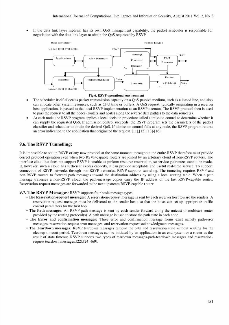
• If the data link layer medium has its own QoS management capability, the packet scheduler is responsible for
negotiation with the data-link layer to obtain the QoS requested by RSVP.
Fig 6. RSVP operational environment
• The scheduler itself allocates packet-transmission capacity on a QoS-passive medium, such as a leased line, and also
can allocate other system resources, such as CPU time or buffers. A QoS request, typically originating in a receiver
host application, is passed to the local RSVP implementation as an RSVP daemon. The RSVP protocol then is used
to pass the request to all the nodes (routers and hosts) along the reverse data path(s) to the data source(s).• At each node, the RSVP program applies a local decision procedure called admission control to determine whether it
can supply the requested QoS. If admission control succeeds, the RSVP program sets the parameters of the packet
classifier and scheduler to obtain the desired QoS. If admission control fails at any node, the RSVP program returns
an error indication to the application that originated the request. [11],[12],[13]-[16].
9.6. The RSVP Tunnelling:
It is impossible to set up RSVP or any new protocol at the same moment throughout the entire RSVP therefore must provide
correct protocol operation even when two RSVP-capable routers are joined by an arbitrary cloud of non-RSVP routers. The
interface cloud that does not support RSVP is unable to perform resource reservation, so service guarantees cannot be made.
If, however, such a cloud has sufficient excess capacity, it can provide acceptable and useful real-time service. To support
connection of RSVP networks through non-RSVP networks, RSVP supports tunneling. The tunneling requires RSVP andnon-RSVP routers to forward path messages toward the destination address by using a local routing table. When a path
message traverses a non-RSVP cloud, the path-message copies carry the IP address of the last RSVP-capable router.
Reservation-request messages are forwarded to the next upstream RSVP-capable router.
9.7. The RSVP Messages: RSVP supports four basic message types:
• The Reservation-request messages: A reservation-request message is sent by each receiver host toward the senders. A
reservation-request message must be delivered to the sender hosts so that the hosts can set up appropriate traffic
control parameters for the first hop.
• The Path messages: An RSVP path message is sent by each sender forward along the unicast or multicast routes
provided by the routing protocol(s). A path message is used to store the path state in each node.• The Error and confirmation messages: Three error and confirmation message forms exist namely path-error
messages, reservation-request error messages, and reservation-request acknowledgment messages.
• The Teardown messages: RSVP teardown messages remove the path and reservation state without waiting for thecleanup timeout period. Teardown messages can be initiated by an application in an end system or a router as the
result of state timeout. RSVP supports two types of teardown messages-path-teardown messages and reservation-
request teardown messages.[22],[24]-[69].
8/4/2019 Paper-17_A Study On Diverse Communication Protocols
http://slidepdf.com/reader/full/paper-17a-study-on-diverse-communication-protocols 10/13
International Journal of Computational Intelligence and Information Security, August 2011 Vol. 2, No. 8
152
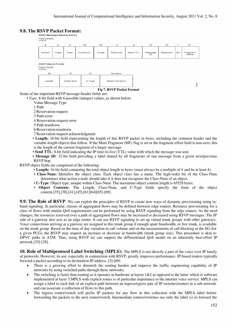
9.8. The RSVP Packet Format:
Fig 7. RSVP Packet Format
Some of the important RSVP message-header fields are:
• Type: 8-bit field with 6 possible (integer) values, as shown below.
Value Message Type1 Path
2 Reservation-request
3 Path-error4 Reservation-request error
5 Path-teardown
6 Reservation-teardown
7 Reservation-request acknowledgment
• Length: 16-bit field representing the length of this RSVP packet in bytes, including the common header and the
variable-length objects that follow. If the More Fragment (MF) flag is set or the fragment offset field is non-zero, this
is the length of the current fragment of a larger message.
• Send TTL: 8-bit field indicating the IP time-to-live (TTL) value with which the message was sent.• Message ID: 32-bit field providing a label shared by all fragments of one message from a given next/previous
RSVP hop.
RSVP object fields are comprised of the following:
• Length: 16-bit field containing the total object length in bytes (must always be a multiple of 4 and be at least 4).
• Class-Num: Identifies the object class. Each object class has a name. The high-order bit of the Class-Numdetermines what action a node should take if it does not recognize the Class-Num of an object.
• C-Type: Object type, unique within Class-Num. The maximum object content length is 65528 bytes.
• Object Contents: The Length, Class-Num, and C-Type fields specify the form of the object
content.[35],[38],[41],[45],[61][64][65]-[69].
9.9. The Role of RSVP: We can exploit the principles of RSVP to create new ways of dynamic provisioning using in-
band signaling. In particular, classes of aggregated flows may be defined between edge routers. Resource provisioning for a
class of flows with similar QoS requirements can be performed by using RSVP signaling from the edge routers. As the need
changes, the resources reserved over a path of aggregated flows may be increased or decreased using RSVP messages. The IP
side of a gateway also acts as an edge router. It can use RSVP signaling to set up virtual trunk groups with other gateways.
Voice connections arriving at a gateway are assigned to this trunk group if enough spare bandwidth, or free trunk, is available
on the trunk group. Based on the time of day variation in call volume and on the measurements of call blocking at the SG (for
a given PCG), the RSVP may request an increase or decrease in bandwidth (trunk group size). This procedure is akin toDPVC paths in ATM. Thus, using RSVP we can support the differentiated QoS model on an inherently best-effort IP
network.[35]-[38].
10. Role of Multiprotocol Label Switching (MPLS): The MPLS is not directly a part of the voice over IP family
of protocols. However, its use, especially in conjunction with RSVP, greatly improves performance. IP-based routers typically
forward a packet according to its destination IP address. [3]-[69]
• There is a growing effort to diminish the routing burden and improve the traffic engineering capability of IP
networks by using switched paths through these networks.
• The switching is faster than routing as it operates in hardware at layers 1&2 as opposed to the latter which is software
implemented at layer 3.MPLS with explicit routes is of particular importance to the internet voice service. MPLS can
assign a label to each link of an explicit path between an ingress/egress pair of IP switches/routers in a sub network
and can associate a collection of flows to this path.• The ingress router/switch will prefix IP packets for any flow in this collection with the MPLS label before
forwarding the packets to the next router/switch. Intermediate routers/switches use only the label (s) to forward the
8/4/2019 Paper-17_A Study On Diverse Communication Protocols
http://slidepdf.com/reader/full/paper-17a-study-on-diverse-communication-protocols 11/13
International Journal of Computational Intelligence and Information Security, August 2011 Vol. 2, No. 8
153
packets until they reach the egress router/switch, where normal forwarding methods can be used. Besides speeding
up the forwarding function, MPLS adds tremendous flexibility to routing in the network.
• Elements such as explicit route selection and QoS-based routing are easier to implement with label switching than
with conventional IP routing. Of course, labels have to be selected and distributed to all routers and edge devices
before label switching can begin for an aggregated flow. Thus, like connection-oriented networking, label switching
is only appropriate for long-lived flows, such as voice connections, video connections, and long file transfers.
• Since routers can provide both the usual datagram forwarding and label switching, they can take advantage of theubiquitous IP infrastructure for routing short-lived flows while providing fast switching of long-lived flows, at least
in some segment of the end-to-end path. Of course, when a collection of flows is grouped for label assignment, only
the collection needs to be long lived. [1],[3],[9],[11]-[12].
Conclusion: This paper gives a extensive coverage about various communication protocols used in communication
transmissions and transactions respectively. To start with we have bring the memories of telephone era basic concept involved
in a typical telephone working phenomenon, which was founded by Sir Alexander Graham Bell. As we aware that protocols
gives the road map for communication transmission of data. Here we have observed that various protocols header formats,
message passing dialog, working aspects of these protocols, audio, video aspects and other multimedia communication needs
of these protocols. We also tried to give a niche of VPN, which nullifies the network resource investment, does the
communication virtually.
In forth coming paper, we focus on voice virtualization, integration of voice application with present cloudcomputing technology aspects.
References:
[1] VoIP: An Overview and Security Aspects, International Journal of Computational Intelligence and Information Security,
Vol. 1 No. 9, November 2010.
[2] Telephony over packet networks by Said Souldi Computer Research Institute of Montreal, IEEE Canadian Review –
Winter/Hiver 1999.
[3] Voice over IP Fundamentals by Jonathan Davidson and James Peter Cisco Systems Techmedia publishers.
[4] [25] IETF, “SDP: Session Description Protocol; SDP: Session Description Protocol; RFC 4566, 2006.[5] S. Khanvilkar, and A. Khokhar, ‘Virtual Private Networks: An Overview with Performance Evaluation”, in IEEE
Communications Magazine, October 2004, pp 146 – 154.[6] C. J. C. Pena, and J. Evans, “Performance Evaluation of Software Virtual Private Networks (VPN)’, 2000, pp 522 – 523.
[7] F. Le Faucher, B. Davie, S. Davari, P. Vaananen, R. Krishnan,P. Cheval, and J. Heinanen, “Multi-protocol label switching
(MPLS) support of differentiated services,” Network Working Group Request for Comments 3270, May 2002,http://tools.ietf.org/html/rfc3270.
[8]Pena CJ, Evans J. Performance Evaluation of Software Virtual Private Networks (VPN). Proceedings of 25th Annual IEEE
Conference on Local Computer Networks . New York: IEEE Computer Society, 2000. 522-523.
[9] A. Bonerjee, J. Drake, J. P. Lang, and B. Turner, “Generalized multiprotocol label switching: An overview of signaling
enhancements
and recovery techniques,” IEEE Commun. Mag., vol. 39, no. 7, pp.144-151, July 2001.[10] K. Tutschku, T. Zinner, A. Nakao, and P. Tran-Gia, ”Network Virtualization:
Implementation Steps Towards the Future Internet”, in Proc. of the Workshop on Overlay and Network Virtualization at
KiVS, Kassel,Germany, Mar. 2009.
[11] V. Alwayn, CCIE Advance MPLS Design and Implementation, Cisco Press, 2002[12] N. Rouhana, E. Horlait, “Differentiated Services and Integrated Services use of MPLS”, IEEE Symposium on Computers
and Communications2000.[13]Internet Engineering Task Force. (2003) RFC 3550. RTP: A Transport Protocol for Real-Time Applications.
http://www.ietf.org/rfc/rfc3550.txt
[14] Internet Engineering Task Force. (2006) RFC 4566. SDP: Session Description Protocol.
http://www.ietf.org/rfc/rfc4566.txt.
[15]Internet Engineering Task Force. (1998) RFC 2460. Internet Protocol, Version 6 (IPv6)Specification.http://www.ietf.org/rfc/rfc2460.txt
[16]Bob Braden (ed.), Lixia Zhang, Steve Berson, Shai Herzog, and Sugih Jamin.Resource Reservation Protocol (RSVP)—
Version 1 Functional Specification.RFC 2205, 1997.
[17]. R. Dantu, S. Fahmy, H. Schulzrinne, and J. Cangussu. Issues and Challenges in Securing VoIP. Computers & Security
(to appear), 2009.
[18]. D. Geneiatakis and C. Lambrinoudakis. An Ontology Description for SIP Security Flaws.Computer Communications,30(6):1367–1374, April 2007.
8/4/2019 Paper-17_A Study On Diverse Communication Protocols
http://slidepdf.com/reader/full/paper-17a-study-on-diverse-communication-protocols 12/13
8/4/2019 Paper-17_A Study On Diverse Communication Protocols
http://slidepdf.com/reader/full/paper-17a-study-on-diverse-communication-protocols 13/13
International Journal of Computational Intelligence and Information Security, August 2011 Vol. 2, No. 8
155
[60]RFC 2705, Media Gateway Control Protocol (MGCP) Version 1.0. M. Arango, A. Dugan, I. Elliott, C. Huitema, S.
Pickett. October 1999.
[61]RFC 2848, The PINT Service Protocol: Extensions to SIP and SDP for IP Access to Telephone Call Services. S. Petrack,
L. Conroy. June 2000.
ftp://ftp.isi.edu/in-notes/rfc2705.txt
[62]RFC 2833, RTP Payload for DTMF Digits, Telephony Tones and Telephony Signals. H. Schulzrinne, S. Petrack. May
2000.
ftp://ftp.isi.edu/in-notes/rfc2848.txt
[63] RFC 2805, Media Gateway Control Protocol Architecture and Requirements. N. Greene, M. Ramalho, B. Rosen. April2000.
ftp://ftp.isi.edu/in-notes/rfc2833.txt
[64] RFC 2658, RTP Payload Format for Pure Voice(tm) Audio. K. McKay. August 1999. ftp://ftp.isi.edu/in-notes/rfc2658.txt
ftp://ftp.isi.edu/in-notes/rfc2805.txt
[65] RFC 2974, Session Announcement Protocol. M. Handley, C. Perkins, E. Whelan. October 2000.
[66]RFC 2897, Proposal for an MGCP Advanced Audio Package. D. Cromwell. August 2000. ftp://ftp.isi.edu/in-
notes/rfc2897.txt
ftp://ftp.isi.edu/in-
notes/rfc2974.txt
[67] Grover, V., & Goslar, M.D. (1993). The Initiation, Adoption, and Implementation of Telecommunications Technologies
in U.S. Organizations. Journal of Management Information Systems, 10(1), 141-163.
[68]J. Halpern, “IP Telephony Security in Depth”. White Paper, Cisco Systems, 2002.
[69] Data Communications and Networking – Behrouz A. Forouzan, 4th Edition, Tata McGraw-Hill, 2006.
[70] http://www.ietf.org/rfc/rfc2974.txt, Session Announcement Protocol.
About the Authors:
Mr.N.Rakesh is a PhD Student in Computer Science at PRIST University Thanjavur, Tamilnadu.Currently
he is working as Senior Lecturer in Department of Information Science and Engineering at KNS Institute of
Technology, Bangalore. He received the B.E in Information Science and Engineering degree from
Visvesvaraya Technological University Belgaum, Karnataka and M.Tech in Computer Science and
Engineering degree from Dr.M.G.R.University, Chennai in 2005 and 2007 respectively. Subsequently
completed M.B.A in Systems from Alagappa University, Karaikudi, Tamilnadu in 2009.He is having 6 years
of experience in academics and published papers in international journals, also is a member of CSI. His
current research activities pertain to VOIP, ATM, Frame Relays, Network Security, Information Security, Wireless sensor
Network and topics related to Networks.
Dr.S.K.Srivatsa received the B.E from Jadavpur University in 1968. He received the M.E and PhD degree
from IISC Bangalore in 1972 and 1976 respectively. He retired as a professor of Electronics and
communication Engineering, Anna University in 2005. Since then, he is a senior Professor in St.Joseph
Engineering College, Chennai, India.
He has produced 35 PhD’s and he is the author of well over 400 publications in reputed Journals and
Conference Proceedings. He is a Life Fellow/Life member in about two dozen professional societies. He is
the recipient of about a dozen awards. His areas of interest include Logic design, graph algorithms,networks, image processing and robotics.


![[MS-SPO]: SharePoint Protocols OverviewMS-SPO... · SharePoint Protocols Overview ... 2018 [MS-SPO]: SharePoint Protocols Overview This overview describes the SharePoint Protocols](https://img.pdfslide.net/doc/110x75/5ece03cb25b3922c1e1461bd/ms-spo-sharepoint-protocols-overview-ms-spo-sharepoint-protocols-overview.jpg)