Embed Size (px)
Citation preview
©ALSTOM Power Systems 2010. All rights reserved. Information contained in this document is provided without liability for information purposes only and is subject to change without notice. No representation or warranty is given or to be implied as to the completeness of information or fitness for any particular purpose. Page 1 / 19
CCS Project with Alstom’s Chilled Ammonia Process at AEP’s Mountaineer Plant Paper No. 72 Rob Bollinger Project Manager American Electric Power 1 Riverside Plaza Columbus, OH 43215 USA Tel: +1 614 716 3766 E-Mail: [email protected]
David Muraskin Alstom Power, Inc. CAP Technology Manager Environmental Control Systems 1409 Centerpoint Blvd Knoxville, TN 37932 USA Tel: +1 865 694 5269 E-Mail: [email protected]
Mike Hammond Project Engineer American Electric Power 1 Riverside Plaza Columbus, OH 43215 USA Tel: +1 614 716 5931 E-Mail: [email protected]
Fred Kozak Alstom Power, Inc. CAP Technology Development Environmental Control Systems 1409 Centerpoint Blvd Knoxville, TN 37932 USA Tel: +1 865 560-1373 E-Mail: [email protected]
Gary Spitznogle CO2 Storage Technical Lead American Electric Power 1 Riverside Plaza Columbus, OH 43215 USA Tel: +1 614 716 3671 E-Mail: [email protected]
Matt Cage Alstom Power, Inc. Project Engineer Environmental Control Systems 1409 Centerpoint Blvd Knoxville, TN 37932 USA Tel: +1 865 694 5888 E-Mail: [email protected]
Brian Sherrick Project Manager American Electric Power 1 Riverside Plaza Columbus, OH 43215 USA Tel: +1 614 716 1923 E-Mail: [email protected]
Michael Varner Alstom Power, Inc. Project Manager Environmental Control Systems 1409 Centerpoint Blvd Knoxville, TN 37932 USA Tel: +1 865 694 5897 E-Mail: [email protected]
©ALSTOM Power Systems 2010. All rights reserved. Information contained in this document is provided without liability for information purposes only and is subject to change without notice. No representation or warranty is given or to be implied as to the completeness of information or fitness for any particular purpose. Page 2 / 19
ABSTRACT Alstom and American Electric Power have jointly participated in the design, installation, start-up, and operation of a carbon capture and storage (CCS) project using Alstom’s Chilled Ammonia Process (CAP) at AEP’s Mountaineer Power Plant. AEP has engaged Battelle to develop a geologic storage system to store the CO2 in porous rock formations located at the power generation facility site. The CCS project “Product Validation Facility (PVF)” at Mountaineer is approximately 20 megawatt electric (MWe) in size and involves the treatment of a slipstream of combustion flue gases from an existing coal-fired boiler. Initial operation of the Product Validation Facility occurred in September 2009 with initial storage of CO2 into a geologic storage formation in October 2009. Alstom’s experiences obtained at other CAP pilot plants have been used to support the Mountaineer PVF and are summarized in the paper. INTRODUCTION The development of CO2 capture technologies is being pursued by US, European, and other global suppliers in collaboration with utility companies, academia and universities as well as Governments particularly in the US (Department of Energy), Europe, Canada and Australia. Several post-combustion solutions are currently being developed. Among the most interesting is Alstom’s Chilled Ammonia Process, which continues to be tested on several pilot and validation facilities. The following paper will first describe the Chilled Ammonia Process and provide an update on the progress made at two of Alstom’s pilot plant facilities, the We Energies and E.ON Karlshamn Field Pilots. In addition, the paper will describe the design, and summarize the development and initial operation of the AEP Mountaineer CO2 Capture Product Validation Facility and Geologic Storage Project. The Field Pilot at We Energies, sized to capture over 15,000 metric tons/year of CO2 at full capacity, commenced operations in June 2008. Tests ended in October 2009 and the gathered operating experience has resulted in a greatly improved understanding of the process and the interactions with the power plant. The Field Pilot at the E.ON Karlshamn location was commissioned in April 2009 and captures CO2 emissions from a boiler combusting a high sulfur fuel oil. . The “Product Validation Facility” (PVF) at American Electric Power’s (AEP) Mountaineer (MTN) plant is designed to treat a 20 MWe slipstream of combustion flue gases from an existing coal-fired boiler. The flue gas is taken downstream of the plant’s existing selective catalytic reduction (SCR), particulate control, and wet flue gas desulfurization (WFGD) systems. The project scope includes CO2 capture, compression, and storage in two geologic reservoirs with injection wellheads located on the plant property. AEP has been working with Battelle to develop the geologic storage system. This unit was inaugurated in September 2009 and is capable of capturing and storing 100,000 metric tons per year of CO2. This unit represents a major step in the technology scale-up process. The Electric Power Research Institute (EPRI) will provide support to obtain measurements and assess the performance of the facility.
©ALSTOM Power Systems 2010. All rights reserved. Information contained in this document is provided without liability for information purposes only and is subject to change without notice. No representation or warranty is given or to be implied as to the completeness of information or fitness for any particular purpose. Page 3 / 19
DESCRIPTION OF THE CHILLED AMMONIA PROCESS The configuration of CAP at each of the three locations where it has been deployed is very similar. Since this paper is intended to focus on the Product Validation Facility at AEP Mountaineer, the process description presented in this section will be based on that facility. Process Chemistry The Chilled Ammonia Process is based on the chemistry of the NH3-CO2-H2O system and the ability of ammoniated solution to absorb CO2 at low temperature and to release the CO2 at moderately elevated temperature. The primary CAP chemical reactions for CO2 capture are presented in Equations 1–4. During absorption, CO2, ammonia, and water combine to form ammonium carbonate, ammonium bicarbonate and ammonium carbamate mainly in ionic forms. CO2 (g) == CO2 (aq) (1) 2NH3 (aq) + H2O (l) + CO2 (aq) == (NH4)2CO3 (aq) (2) (NH4)2CO3 (aq) + CO2 (aq) + H2O (l) == 2(NH4)HCO3 (aq) (3) (NH4)2CO3 (aq) === (NH4)NH2CO2 (aq) + H2O (l) (4) The reactions in the process are all reversible and their direction depends on pressure, temperature and concentration in the system. Equations 1-4 are exothermic reactions in the left to right direction requiring removal of heat from the process in order to maintain the desired CO2 absorption temperature. Equations 1-4 are endothermic reactions in the right to left direction that require energy to produce the desired products. Ammonium bicarbonate is the least soluble salt in the system and depending on process conditions, primarily concentration and temperature, ammonium bicarbonate may precipitate as crystalline salt, as shown in equation 5. (NH4)HCO3 (aq) === (NH4)HCO3 (s) (5) Overall chemical reactions associated with removal of residual SO2 in the flue gas in the cleaning and cooling stage of the CAP process are provided below in Equations 6 and 7.
SO2(g) + 2NH3(g) + H2O(aq) ⇒ (NH4)2SO3(aq) (6) (NH4)2SO3(aq)+ 1/2O2(g) ⇒ (NH4)2SO4(aq) (7)
©ALSTOM Power Systems 2010. All rights reserved. Information contained in this document is provided without liability for information purposes only and is subject to change without notice. No representation or warranty is given or to be implied as to the completeness of information or fitness for any particular purpose. Page 4 / 19
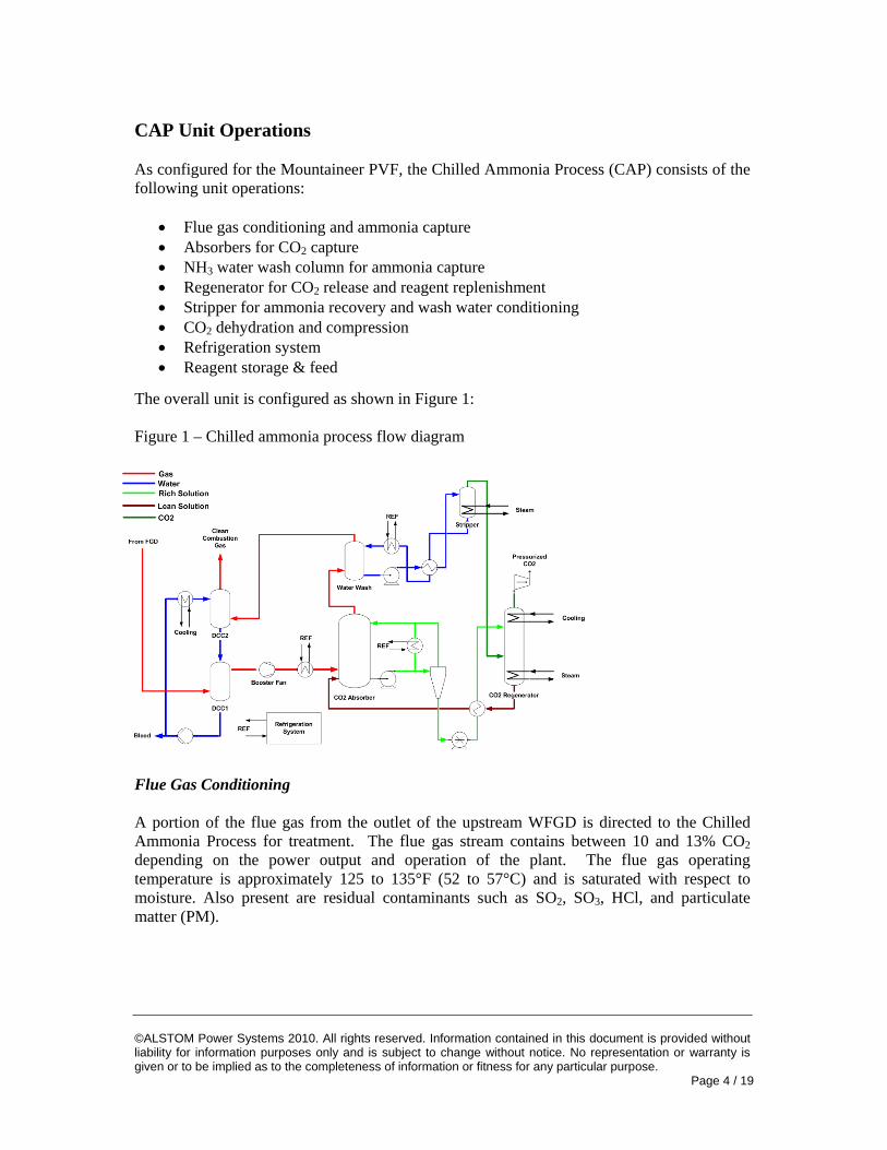
CAP Unit Operations As configured for the Mountaineer PVF, the Chilled Ammonia Process (CAP) consists of the following unit operations:
• Flue gas conditioning and ammonia capture • Absorbers for CO2 capture • NH3 water wash column for ammonia capture • Regenerator for CO2 release and reagent replenishment • Stripper for ammonia recovery and wash water conditioning • CO2 dehydration and compression • Refrigeration system • Reagent storage & feed
The overall unit is configured as shown in Figure 1: Figure 1 – Chilled ammonia process flow diagram
Flue Gas Conditioning A portion of the flue gas from the outlet of the upstream WFGD is directed to the Chilled Ammonia Process for treatment. The flue gas stream contains between 10 and 13% CO2 depending on the power output and operation of the plant. The flue gas operating temperature is approximately 125 to 135°F (52 to 57°C) and is saturated with respect to moisture. Also present are residual contaminants such as SO2, SO3, HCl, and particulate matter (PM).
©ALSTOM Power Systems 2010. All rights reserved. Information contained in this document is provided without liability for information purposes only and is subject to change without notice. No representation or warranty is given or to be implied as to the completeness of information or fitness for any particular purpose. Page 5 / 19
The Flue Gas Conditioning system consists of two packed bed sections, Direct Contact Cooler 1 (DCC1) and Direct Contact Cooler 2 (DCC2), and a circulation loop through an evaporative cooling tower. The flue gas is cooled in DCC1 to condense and remove moisture from the flue gas. The solution pH in the DCC1/DCC2 loop is controlled to facilitate high SO2 capture efficiency in the DCC1 and high NH3 capture efficiency in DCC2. The use of the incoming SO2 and acid gases is effective in the removal of ammonia leaving the CAP as one (1) mole of SO2 captured in DCC1 reacts with two (2) moles of NH3 captured in DCC2 to produce ammonium sulphate product. In the AEP Mountaineer PVF the upstream WFGD operates at very high SO2 capture efficiency with low residual SOx in the flue gas. As such, sulfuric acid is added in the DCC2 to capture residual ammonia in the flue gas prior to exiting the Chilled Ammonia Process. The DCC2 design is an efficient ammonia removal device that results in high capture efficiencies and low ammonia emissions at the AEP Mountaineer PVF. The DCC2 design consistently demonstrates ammonia emissions of less than 2 ppm in the clean flue gas (refer to Figure 10). Both sulfuric acid and absorbed SO2 react with ammonia to form ammonium sulfate (AS). To control the AS concentration, a portion of this circulating stream is bled from the system as a by-product that can be used as fertilizer. Absorbers Conditioned flue gas entering the CO2 absorber is contacted with an ammoniated solution to absorb the CO2 from the flue gas. The ammoniated scrubbing solution consists of the following constituents present in the ionic form:
- Ammonia - Ammonium Carbonate - Ammonium Bicarbonate - Ammonium Carbamate - Water
Depending on the temperature and concentration of the carbonates and bicarbonates relative to the amount of ammonia, solids may form at different locations in the absorber bed. Based upon the experience gained at the pilot plants, the absorber conditions are controlled to avoid the precipitation of solids. A key variable for determining the conditions for solids precipitation is the NH3/CO2 mole ratio, or R value of the scrubbing solution. The lower the R value, the richer the solution with respect to CO2 and the potential for the precipitation of solids is increased. In addition, the solution R value is important in the capture rate of CO2 from the flue gas. Higher solution R values result in an increase in CO2 capture efficiency. The Absorption System at the AEP Mountaineer PVF consists of two absorption vessels, A&B, each with a different primary function in treating the flue gas. Absorber A is the primary vessel where CO2 is captured. In this vessel, ammoniated solution is contacted with the flue gas over a packed bed to achieve the mass transfer needed to absorb CO2. Heat generated by the exothermic absorption reactions is removed from the process with a refrigeration system. Absorber B operates at lower flue gas temperature and is designed to capture additional CO2 and to reduce the ammonia emission from the absorber system.
©ALSTOM Power Systems 2010. All rights reserved. Information contained in this document is provided without liability for information purposes only and is subject to change without notice. No representation or warranty is given or to be implied as to the completeness of information or fitness for any particular purpose. Page 6 / 19
Water Wash NH3 Column Depending on the Absorber operating temperature, the strength of the ionic solution, and the solution R value, the treated flue gas leaving the absorber system will contain varying amounts of gaseous ammonia. This ammonia in the flue gas must be controlled to desired levels, captured, and returned to the process in order to minimize ammonia losses from the system and in order to maintain stable operating conditions. The Water Wash NH3 column is designed to absorb the majority of the incoming ammonia for return to the process. Regeneration Rich ammoniated solution is pumped from the absorber to the regenerator through a series of heat exchangers in order to recover heat from the lean ammoniated stream leaving the regenerator bottom. In the Regenerator column, as heat is applied, CO2 evolves from the rich solution. The composition of the vapor stream leaving the Regenerator is a function of temperature, pressure, the relative concentrations of CO2, ammonia, and water in solution. At moderately elevated temperature, the vapor pressure of CO2 in the ammoniated solution increases rapidly while the vapor pressure of the ammonia and water remain relatively low. As a result, the CO2 is emitted from the regenerator at high pressure to provide a significant feature of the technology. The higher CO2 product stream pressure significantly reduces the downstream CO2 compressor power and size. In addition, the CO2 from the regenerator contains very low concentrations of ammonia (<0.2%) and water vapor (<2%) resulting in low overall heat consumption. The CO2 product stream can be easily washed and cooled to produce an extremely pure CO2 gas stream. Ammonia Recovery Stripper An ammonia recovery stripper is included in the Chilled Ammonia Process to strip ammonia from ammoniated water. The ammoniated water is obtained from the following sources:
• Saturated water from the Water Wash (continuous) • Saturated solution from the Regenerator overhead (continuous) • Lean Solution to the Absorbers (intermittent, to maintain water balance.)
Ammonia recovery strippers are very common and many hundreds of commercial units are in operation worldwide. Two types of ammonia strippers commonly used are:
• Atmospheric pressure strippers commonly used for sour water strippers that use low pressure steam as a source of heat.
• Elevated pressure strippers common in the urea industry that typically operate above 100 psig (6.9 bar g) using medium pressure steam as their heat source.
The advantage of using an elevated pressure stripper in the CAP system is the ability to recover practically all the heat used in the stripper in the regenerator. The disadvantage is the need to use higher value medium pressure steam that is not always available for extraction from the power generation steam cycle.
©ALSTOM Power Systems 2010. All rights reserved. Information contained in this document is provided without liability for information purposes only and is subject to change without notice. No representation or warranty is given or to be implied as to the completeness of information or fitness for any particular purpose. Page 7 / 19
We Energies, E.ON Karlshamn, and the AEP Mountaineer PVF were all designed as elevated pressure strippers with operation at approximately 300-350 psig (20-22 bar g). The design allows the stripper overhead with all its heat content to flow directly to the regenerator. When this concept was tested at We Energies and E.ON Karlshamn, it was found that due to heat supply limitations the stripper performed better at lower pressure than at higher pressure. However, the stripper at the E.ON Karlshamn pilot plant operated successfully at the design 330 psig (23 bar g) pressure for long periods and as long as steam pressure was sufficiently high. The Mountaineer PVF experiences periods, mainly at night when the boiler operate at part load, where the medium pressure steam supply is reduced making elevated pressure stripping impossible for the duration of the part load operation. As a result, the Mountaineer PVF ammonia recovery stripper is operated at an “off-design” low pressure condition to achieve the ammonia recovery objective at the cost of increased cooling demand to accommodate the loss of heat in the stripper overhead return to the absorber instead of the regenerator. Commercial CAP designs will include modifications needed to capture the low pressure stripper overhead stream latent and sensible heat instead of the current elevated pressure stripper design as installed at the Mountaineer PVF. CO2 Dehydration and Compression The CO2 captured at the AEP Mountaineer facility PVF is sequestered in one of two on-site wells. At equilibrium under design temperature and pressure conditions, the CO2 product stream leaving the regenerator system is expected to have a purity of greater than 99.7% while containing less than 2500 ppmv moisture and less than 50 ppmv ammonia. As the design of the sequestration system progressed, the preferred moisture content was reduced to less than 600 ppmv. Different approaches were evaluated for achieving this moisture level. The finalized design selected for the project includes the use of the refrigeration system and in-line heat exchanger to reduce the CO2 product stream temperature to less than 45°F (7°C) in order to condense water from the gas. The CO2 product stream leaving the regenerator at 300 psig (21 bar g) is compressed to 1500 psig (193 bar g) using a two-stage reciprocating compression system. The fluid leaving the compression system is transported to a metering area where the CO2 can be directly injected into one of two wells for storage or, if required by well-head pressure, a multistage pump can increase the injection pressure of 3000 psig (207 bar g). Refrigeration Systems The Mountaineer PVF is provided with two refrigeration systems for low temperature and high temperature process cooling applications. Because of site restrictions, these systems use the fluorohydrocarbon, R-410A as a refrigerant instead of the more efficient anhydrous ammonia. In addition, to improve system efficiency, a “free cooling” pump designed to circulate refrigerant when ambient temperatures are sufficiently low has been provided. The free cooling pump substitutes liquid pumping instead of refrigerant gas compression which reduces power demand.

©ALSTOM Power Systems 2010. All rights reserved. Information contained in this document is provided without liability for information purposes only and is subject to change without notice. No representation or warranty is given or to be implied as to the completeness of information or fitness for any particular purpose. Page 8 / 19
Figure 2: We Energies CAP Field Pilot
UPDATE ON THE CHILLED AMMONIA FIELD UNITS – PROGESS IN THE TECHNOLOGY DEVELOPMENT We Energies Field Validation Unit The Chilled Ammonia field pilot was located at the We Energies Pleasant Prairie Power Plant (“P4”), in, Wisconsin, US. P4 is retrofitted with a wet Flue Gas Desulphurization system to control SO2 emissions. Engineering for the field pilot was initiated in March 2007 with equipment purchases and delivery continuing through March 2008 (refer to Figure 2).
This facility was constructed in association with the Electric Power Research Institute (EPRI) representing a global community of 37 utility companies. The plant processed a 5 MWth equivalent slip stream of flue gas and captured CO2 at a rate of 15,000 metric tons/yr. The program, which was completed on October 31, 2009, satisfied the “Proof of Concept” objectives for the project. The major technology issues addressed by this project included:
• Would CAP unit operations be effective with coal fired flue gas? • What levels of CO2 capture could be demonstrated? • What quality CO2 could be produced? • Could ammonia emissions be controlled? • Could CO2 rich ammoniated solution be regenerated at elevated pressures? • Would energy utilization fall within design parameters? • Were there any mechanical and material selection issues that need to be addressed?
The key success factors that were demonstrated during this run included:
• CO2 capture efficiency at averaged 88.6% over sustained operating period, • Consistent production of CO2 at 300 psig (21 bar g) without gas compression • CO2 product quality greater than 99%, • Residual Ammonia in the flue gas of less than 10 ppmv leaving the CAP.
In addition to the evaluation of the process parameters, operational benchmarks achieved during the program included:
• 7700 hours of operation over a 16 month period (70% availability) • Understanding the relationship between key operating parameters • Impact of power plant transients on CAP operation • Materials selection criteria confirmed
©ALSTOM Power Systems 2010. All rights reserved. Information contained in this document is provided without liability for information purposes only and is subject to change without notice. No representation or warranty is given or to be implied as to the completeness of information or fitness for any particular purpose. Page 9 / 19
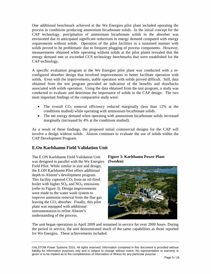
Figure 3: Karlshamn Power Plant (Sweden)
One additional benchmark achieved at the We Energies pilot plant included operating the process in conditions producing ammonium bicarbonate solids. In the initial concept for the CAP technology, precipitation of ammonium bicarbonate solids in the absorber was envisioned due to anticipated significant reductions in energy demand compared with energy requirements without solids. Operation of the pilot facilities in a sustained manner with solids proved to be problematic due to frequent plugging of process components. However, measurements obtained while operating without solids at the pilot plants revealed that the energy demand met or exceeded CCS technology benchmarks that were established for the CAP technology. A specific evaluation program at the We Energies pilot plant was conducted with a re-configured absorber design that involved improvements to better facilitate operation with solids. Even with the improvements, stable operation with solids proved difficult. Still, data obtained from the test program provided an indication of the benefits and drawbacks associated with solids operation. Using the data obtained from the test program, a study was conducted to evaluate and determine the importance of solids in the CAP design. The two most important findings of the comparative study were:
• The overall CO2 removal efficiency reduced marginally (less than 12% at the conditions studied) while operating with ammonium bicarbonate solids.
• The net energy demand when operating with ammonium bicarbonate solids increased marginally (increased by 4% at the conditions studied).
As a result of these findings, the proposed initial commercial designs for the CAP will involve a design without solids. Alstom continues to evaluate the use of solids within the CAP Development Program. E.On Karlshamn Field Validation Unit The E.ON Karlshamn Field Validation Unit was designed in parallel with the We Energies Field Pilot. While similar in size and design, the E.ON Karlshamn Pilot offers additional depth to Alstom’s development program. This facility captured CO2 from an oil-fired boiler with higher SOX and NOX emissions (refer to Figure 3). Design improvements were made to the water wash system to improve ammonia removal from the flue gas leaving the CO2 absorber. Finally, this pilot plant was equipped with additional instrumentation to refine Alstom’s understanding of the process.
The unit began operations in April 2009 and remained in service for over 2000 hours. During the period in service, the unit demonstrated much of the same capabilities as those reported for We Energies. These achievements included:
©ALSTOM Power Systems 2010. All rights reserved. Information contained in this document is provided without liability for information purposes only and is subject to change without notice. No representation or warranty is given or to be implied as to the completeness of information or fitness for any particular purpose. Page 10 / 19
• CO2 capture efficiency at 90%, • Consistent production of CO2 at 300 psig without gas compression • CO2 product quality greater than 99%, • Residual ammonia in the flue gas of less than 10 ppmv.
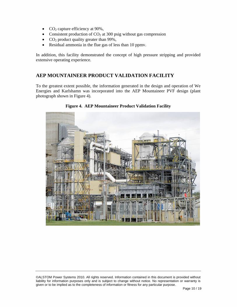
In addition, this facility demonstrated the concept of high pressure stripping and provided extensive operating experience. AEP MOUNTAINEER PRODUCT VALIDATION FACILITY To the greatest extent possible, the information generated in the design and operation of We Energies and Karlshamn was incorporated into the AEP Mountaineer PVF design (plant photograph shown in Figure 4).
Figure 4. AEP Mountaineer Product Validation Facility
©ALSTOM Power Systems 2010. All rights reserved. Information contained in this document is provided without liability for information purposes only and is subject to change without notice. No representation or warranty is given or to be implied as to the completeness of information or fitness for any particular purpose. Page 11 / 19
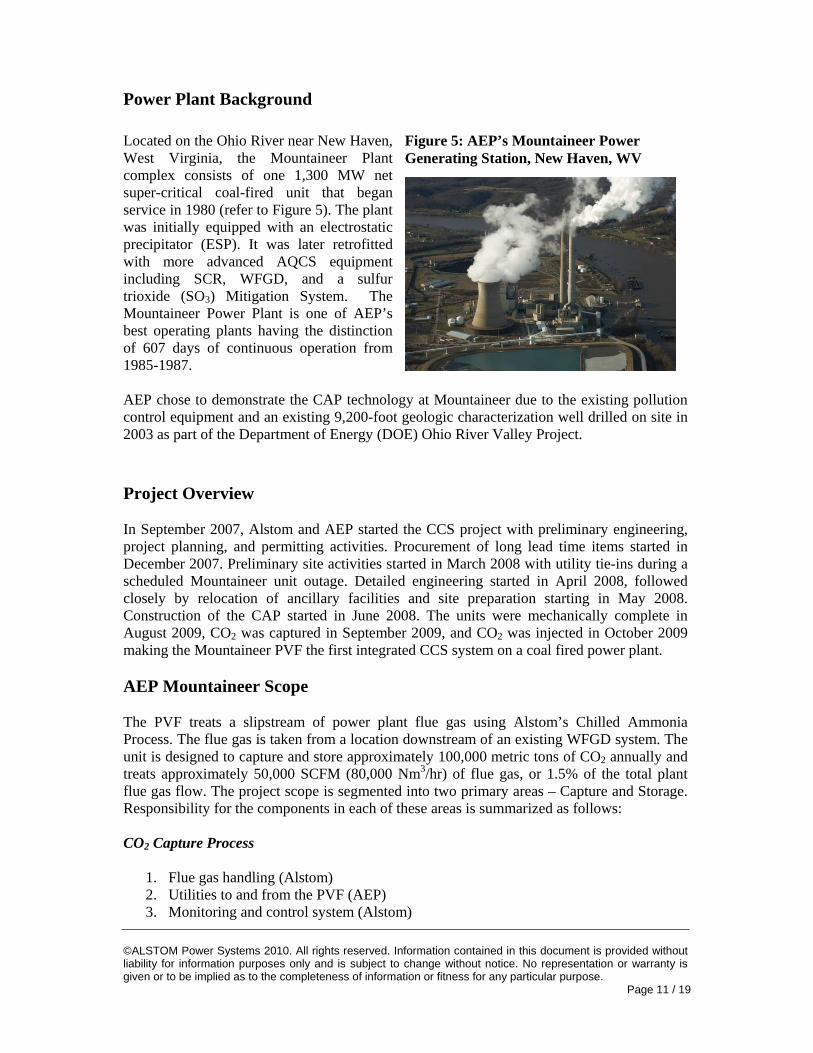
Figure 5: AEP’s Mountaineer Power Generating Station, New Haven, WV
Power Plant Background Located on the Ohio River near New Haven, West Virginia, the Mountaineer Plant complex consists of one 1,300 MW net super-critical coal-fired unit that began service in 1980 (refer to Figure 5). The plant was initially equipped with an electrostatic precipitator (ESP). It was later retrofitted with more advanced AQCS equipment including SCR, WFGD, and a sulfur trioxide (SO3) Mitigation System. The Mountaineer Power Plant is one of AEP’s best operating plants having the distinction of 607 days of continuous operation from 1985-1987. AEP chose to demonstrate the CAP technology at Mountaineer due to the existing pollution control equipment and an existing 9,200-foot geologic characterization well drilled on site in 2003 as part of the Department of Energy (DOE) Ohio River Valley Project. Project Overview In September 2007, Alstom and AEP started the CCS project with preliminary engineering, project planning, and permitting activities. Procurement of long lead time items started in December 2007. Preliminary site activities started in March 2008 with utility tie-ins during a scheduled Mountaineer unit outage. Detailed engineering started in April 2008, followed closely by relocation of ancillary facilities and site preparation starting in May 2008. Construction of the CAP started in June 2008. The units were mechanically complete in August 2009, CO2 was captured in September 2009, and CO2 was injected in October 2009 making the Mountaineer PVF the first integrated CCS system on a coal fired power plant. AEP Mountaineer Scope The PVF treats a slipstream of power plant flue gas using Alstom’s Chilled Ammonia Process. The flue gas is taken from a location downstream of an existing WFGD system. The unit is designed to capture and store approximately 100,000 metric tons of CO2 annually and treats approximately 50,000 SCFM (80,000 Nm3/hr) of flue gas, or 1.5% of the total plant flue gas flow. The project scope is segmented into two primary areas – Capture and Storage. Responsibility for the components in each of these areas is summarized as follows: CO2 Capture Process
1. Flue gas handling (Alstom) 2. Utilities to and from the PVF (AEP) 3. Monitoring and control system (Alstom)

©ALSTOM Power Systems 2010. All rights reserved. Information contained in this document is provided without liability for information purposes only and is subject to change without notice. No representation or warranty is given or to be implied as to the completeness of information or fitness for any particular purpose. Page 12 / 19
4. PVF island steel (Alstom) 5. Cooling and cleaning system (Alstom) 6. CO2 absorption system (Alstom) 7. CO2 regeneration system (Alstom) 8. CO2 compression for CO2 transportation (Alstom) 9. Handling of PVF bleed stream (AEP)
CO2 Storage
1. CO2 transport pipeline (AEP) 2. Pump to reach injection pressure (AEP) 3. Finish existing well for injection (Battelle) 4. Install second injection well (Battelle) 5. Install monitoring wells (Battelle) 6. Monitoring, mitigation, and accounting (MMA) system (Battelle)
Unit Operations at AEP Mountaineer PVF The AEP Mountaineer PVF (Figure 6) incorporated several design improvements that were developed as a result of the design and initial operation at We Energies.
Figure 6. AEP Mountaineer Product Validation Facility
These include: • Single stage absorber system designed to achieve 75% CO2 capture efficiency and sized
to achieve an annual capture rate of 100,000 metric tons/yr. • The Water Wash column which is used to remove ammonia from the flue gas from the
CO2 absorber was reduced from three recirculated beds in series at We Energies to two beds. The top bed is a once through design and serves as a polishing stage. The lower bed is a re-circulated system where the primary amount of NH3 is absorbed. The Water Wash column uses stripped water to absorb NH3 from the residual flue gas. The ammoniated
©ALSTOM Power Systems 2010. All rights reserved. Information contained in this document is provided without liability for information purposes only and is subject to change without notice. No representation or warranty is given or to be implied as to the completeness of information or fitness for any particular purpose. Page 13 / 19
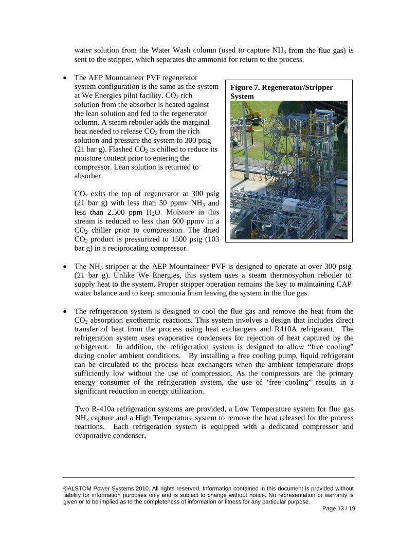
Figure 7. Regenerator/Stripper System
water solution from the Water Wash column (used to capture NH3 from the flue gas) is sent to the stripper, which separates the ammonia for return to the process.
• The AEP Mountaineer PVF regenerator
system configuration is the same as the system at We Energies pilot facility. CO2 rich solution from the absorber is heated against the lean solution and fed to the regenerator column. A steam reboiler adds the marginal heat needed to release CO2 from the rich solution and pressure the system to 300 psig (21 bar g). Flashed CO2 is chilled to reduce its moisture content prior to entering the compressor. Lean solution is returned to absorber.
CO2 exits the top of regenerator at 300 psig (21 bar g) with less than 50 ppmv NH3 and less than 2,500 ppm H2O. Moisture in this stream is reduced to less than 600 ppmv in a CO2 chiller prior to compression. The dried CO2 product is pressurized to 1500 psig (103 bar g) in a reciprocating compressor.
• The NH3 stripper at the AEP Mountaineer PVF is designed to operate at over 300 psig
(21 bar g). Unlike We Energies, this system uses a steam thermosyphon reboiler to supply heat to the system. Proper stripper operation remains the key to maintaining CAP water balance and to keep ammonia from leaving the system in the flue gas.
• The refrigeration system is designed to cool the flue gas and remove the heat from the
CO2 absorption exothermic reactions. This system involves a design that includes direct transfer of heat from the process using heat exchangers and R410A refrigerant. The refrigeration system uses evaporative condensers for rejection of heat captured by the refrigerant. In addition, the refrigeration system is designed to allow “free cooling” during cooler ambient conditions. By installing a free cooling pump, liquid refrigerant can be circulated to the process heat exchangers when the ambient temperature drops sufficiently low without the use of compression. As the compressors are the primary energy consumer of the refrigeration system, the use of ‘free cooling” results in a significant reduction in energy utilization.
Two R-410a refrigeration systems are provided, a Low Temperature system for flue gas NH3 capture and a High Temperature system to remove the heat released for the process reactions. Each refrigeration system is equipped with a dedicated compressor and evaporative condenser.
©ALSTOM Power Systems 2010. All rights reserved. Information contained in this document is provided without liability for information purposes only and is subject to change without notice. No representation or warranty is given or to be implied as to the completeness of information or fitness for any particular purpose. Page 14 / 19
CO2 Handling & Storage Taking control of the supercritical CO2 at the outlet of Alstom’s compressor is one of the key interface points between AEP and Alstom. AEP installed the 4-inch (100 mm) carbon steel pipe at Alstom’s compressor outlet. Carbon steel is an acceptable material for the transport system due to the low moisture content (< 600 ppm) and low ammonia levels (< 50 ppm) in the CO2 product stream. Moisture or ammonia concentrations above these values could lead to corrosion or erosion issues over time requiring specialized materials of construction and frequent maintenance. The supercritical CO2 is transported via pipeline approximately 1,200 feet (366 m) to the injection wells. The CO2 can then be injected into one or both of two injection wells or sent to a booster pump to increase the CO2 pressure to up to 3000 psi (206 bar) for injection. The key objective of the storage project is validating CO2 injection and storage in the geologic reservoirs. Geologic formations need to be both porous and permeable in order to serve as storage reservoirs. In general, sandstone formations make excellent geologic storage reservoirs, whereas dolomite, shale, and limestone formations are excellent caprock for geologic storage. At Mountaineer, the CO2 will be injected into one or both of two: the Rose Run Sandstone, approximately 7,800 ft (2377 m) below ground; and the Copper Ridge B-Zone, approximately 8,200 ft (2499 m) below ground. Data collected from the storage efforts of this project will be compared with modeling results and predicted CO2 behavior. Battelle’s modelling simulations based on the seismic survey, well logging, and core and reservoir testing data from the first well, AEP-1, will be validated and tuned based on this real-world information. This project offers a rare opportunity for authenticating a large pool of data collected during characterization. Following the active injection period, the CO2 placed below ground will continue to be monitored for migration and confinement for up to 20 years in accordance with the Underground Injection Control (UIC) permit. CO2 Storage Permitting Permitting this first-of-a-kind CO2 storage project with the appropriate West Virginia agencies was another key task for the storage project. The list of permits for the project included:
• Underground Injection Control (UIC) – WV DEP • Well work permits for drilling deep wells– WV DEP • NPDES permit modification – WV DEP • Storm Water Construction Permit – WV DEP • Corps permit notification – Corps of Engineers
The two most significant permits for the storage project were the well work permits needed to drill the monitoring and injection wells and the Underground Injection Control (UIC) Permit needed to operate the CO2 injection wells. Well work permits are needed in West Virginia for deep wells that are used for geologic characterization or other non-producing deep wells. AEP submitted the monitoring well work permit applications in March 2008 and received them in June 2008. AEP submitted the injection well work permit applications in July 2008 and received them in August 2008.
©ALSTOM Power Systems 2010. All rights reserved. Information contained in this document is provided without liability for information purposes only and is subject to change without notice. No representation or warranty is given or to be implied as to the completeness of information or fitness for any particular purpose. Page 15 / 19
The UIC Permit for this project is a Class V experimental well permit. It is important to note that the permitting activities for this project were undertaken prior to establishment of a new permitting classification for CO2 injection. AEP filed the project UIC permit application on February 8, 2008 and received the permit in May 2009. The Department of Energy (DOE)-sponsored Ohio River Valley Project provided most of the information needed for this permit. The UIC permit also includes modeling data from Battelle’s proprietary STOMPCO2 model, including a map showing the 3,490 ft (1064 m) radius which indicates the extent of the CO2 plume projected on the surface (“Area of Review”), which was based on several conservative assumptions. This area assumes that all of the CO2 is injected into one zone at the maximum capture rate. For geologic storage of CO2, there are several questions and concerns that need to be addressed before programs are implemented on a commercial scale basis, such as:
• Who owns the rights to the pore space in the geologic reservoirs thousands of feet under ground? How can those rights be acquired and /or utilized to support commercial storage projects?
• Are uniform federal standards needed to govern storage requirements in order to facilitate the use of interstate formations?
• How will liability protection be handled during project operation, post-closure, and ultimately during the long-term stewardship period?
• What are the risks and liability complications for situations when CO2 or pressure effected zone from one source combines underground with CO2 or pressure effected zone from other source(s)?
For the Mountaineer CO2 storage project, AEP owns most of the property and mineral rights within the Area of Review. AEP is researching pore space usage mineral rights issues for the property not owned by AEP and is working with West Virginia to craft language that addresses corrective action during the term of the UIC permit. Questions regarding third party liability and insurance coverage are also still being reviewed. AEP Mountaineer PVF Commissioning and Start-Up Experience The PVF was started on September 1, 2009 capturing CO2 from power plant flue gas. On October 1, 2009, CO2 was injected into the wells and the combination of capture and storage of flue gas from a coal-fired power plant was demonstrated for the first time. As with any new process, the operations team has been slowly bringing the unit up to design conditions within the context of the improvements that were developed during the field pilot runs. The issues confronted by the operations team included:
• Utilization of solid reagent to build ammonia concentration • Operation of the refrigeration system at turndown conditions • Operation of compressor at turndown rates • Rich solution regenerator feed temperature gradient • Flue gas moisture condensation • Variations in steam conditions
©ALSTOM Power Systems 2010. All rights reserved. Information contained in this document is provided without liability for information purposes only and is subject to change without notice. No representation or warranty is given or to be implied as to the completeness of information or fitness for any particular purpose. Page 16 / 19
• Modification of stripper operating pressure to better accommodate the available steam source
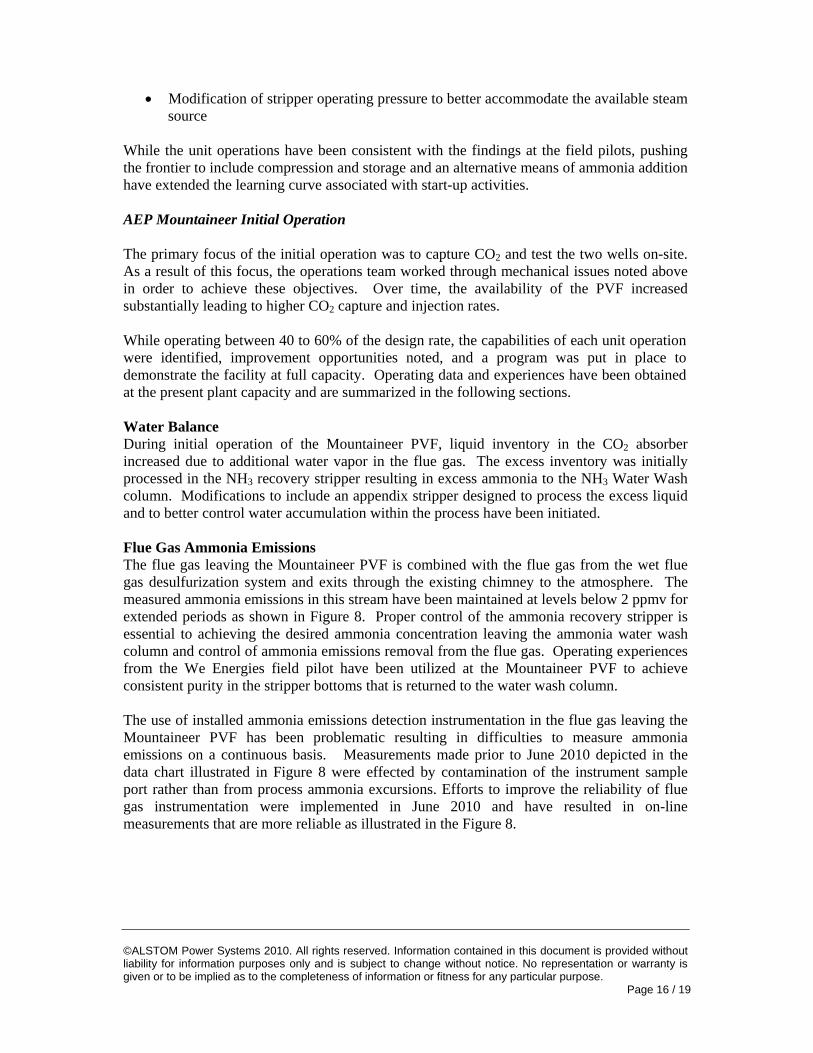
While the unit operations have been consistent with the findings at the field pilots, pushing the frontier to include compression and storage and an alternative means of ammonia addition have extended the learning curve associated with start-up activities. AEP Mountaineer Initial Operation The primary focus of the initial operation was to capture CO2 and test the two wells on-site. As a result of this focus, the operations team worked through mechanical issues noted above in order to achieve these objectives. Over time, the availability of the PVF increased substantially leading to higher CO2 capture and injection rates. While operating between 40 to 60% of the design rate, the capabilities of each unit operation were identified, improvement opportunities noted, and a program was put in place to demonstrate the facility at full capacity. Operating data and experiences have been obtained at the present plant capacity and are summarized in the following sections. Water Balance During initial operation of the Mountaineer PVF, liquid inventory in the CO2 absorber increased due to additional water vapor in the flue gas. The excess inventory was initially processed in the NH3 recovery stripper resulting in excess ammonia to the NH3 Water Wash column. Modifications to include an appendix stripper designed to process the excess liquid and to better control water accumulation within the process have been initiated. Flue Gas Ammonia Emissions The flue gas leaving the Mountaineer PVF is combined with the flue gas from the wet flue gas desulfurization system and exits through the existing chimney to the atmosphere. The measured ammonia emissions in this stream have been maintained at levels below 2 ppmv for extended periods as shown in Figure 8. Proper control of the ammonia recovery stripper is essential to achieving the desired ammonia concentration leaving the ammonia water wash column and control of ammonia emissions removal from the flue gas. Operating experiences from the We Energies field pilot have been utilized at the Mountaineer PVF to achieve consistent purity in the stripper bottoms that is returned to the water wash column. The use of installed ammonia emissions detection instrumentation in the flue gas leaving the Mountaineer PVF has been problematic resulting in difficulties to measure ammonia emissions on a continuous basis. Measurements made prior to June 2010 depicted in the data chart illustrated in Figure 8 were effected by contamination of the instrument sample port rather than from process ammonia excursions. Efforts to improve the reliability of flue gas instrumentation were implemented in June 2010 and have resulted in on-line measurements that are more reliable as illustrated in the Figure 8.
©ALSTOM Power Systems 2010. All rights reserved. Information contained in this document is provided without liability for information purposes only and is subject to change without notice. No representation or warranty is given or to be implied as to the completeness of information or fitness for any particular purpose. Page 17 / 19
Figure 8. Mountaineer PVF Flue Gas Ammonia Emission Data
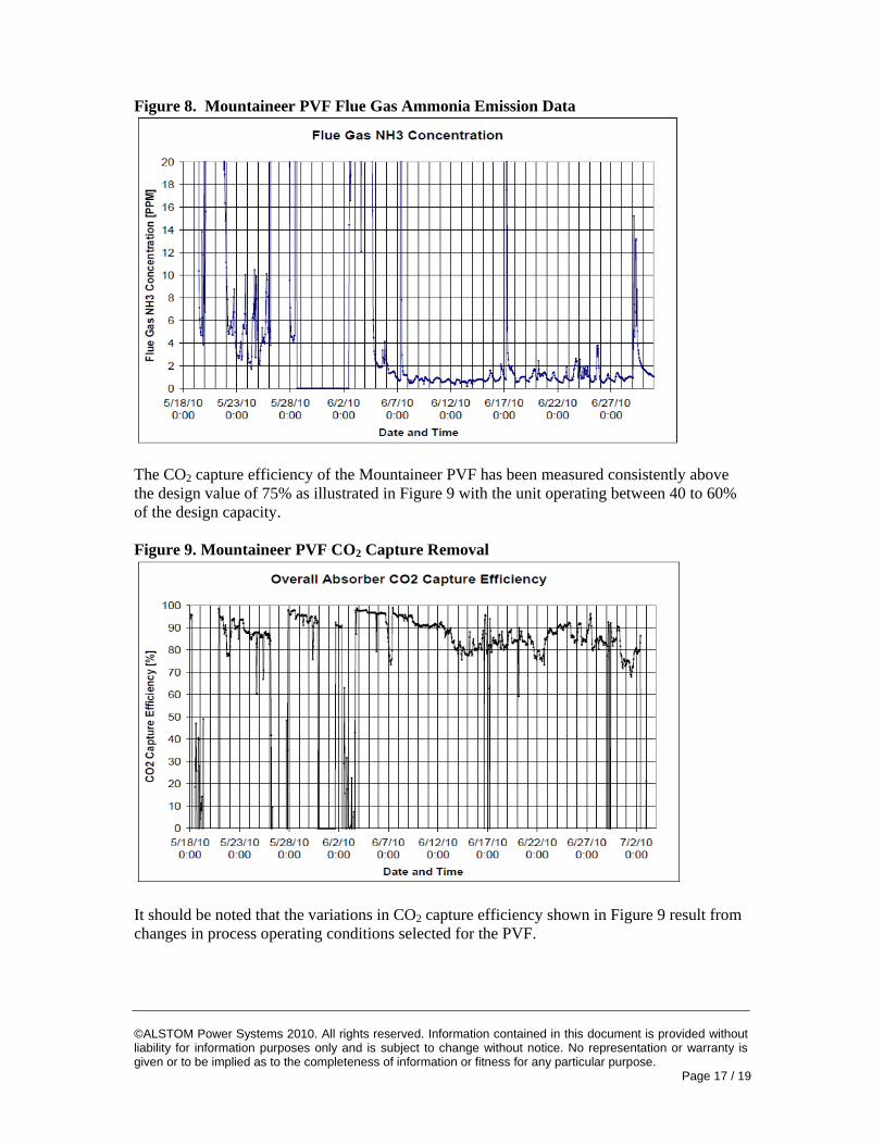
The CO2 capture efficiency of the Mountaineer PVF has been measured consistently above the design value of 75% as illustrated in Figure 9 with the unit operating between 40 to 60% of the design capacity. Figure 9. Mountaineer PVF CO2 Capture Removal
It should be noted that the variations in CO2 capture efficiency shown in Figure 9 result from changes in process operating conditions selected for the PVF.
©ALSTOM Power Systems 2010. All rights reserved. Information contained in this document is provided without liability for information purposes only and is subject to change without notice. No representation or warranty is given or to be implied as to the completeness of information or fitness for any particular purpose. Page 18 / 19
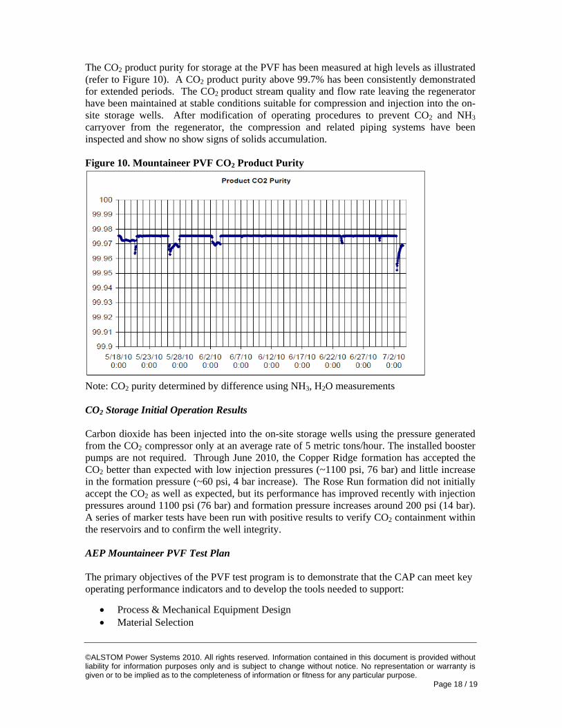
The CO2 product purity for storage at the PVF has been measured at high levels as illustrated (refer to Figure 10). A CO2 product purity above 99.7% has been consistently demonstrated for extended periods. The CO2 product stream quality and flow rate leaving the regenerator have been maintained at stable conditions suitable for compression and injection into the on-site storage wells. After modification of operating procedures to prevent CO2 and NH3 carryover from the regenerator, the compression and related piping systems have been inspected and show no show signs of solids accumulation. Figure 10. Mountaineer PVF CO2 Product Purity
Note: CO2 purity determined by difference using NH3, H2O measurements CO2 Storage Initial Operation Results Carbon dioxide has been injected into the on-site storage wells using the pressure generated from the CO2 compressor only at an average rate of 5 metric tons/hour. The installed booster pumps are not required. Through June 2010, the Copper Ridge formation has accepted the CO2 better than expected with low injection pressures (~1100 psi, 76 bar) and little increase in the formation pressure (~60 psi, 4 bar increase). The Rose Run formation did not initially accept the CO2 as well as expected, but its performance has improved recently with injection pressures around 1100 psi (76 bar) and formation pressure increases around 200 psi (14 bar). A series of marker tests have been run with positive results to verify CO2 containment within the reservoirs and to confirm the well integrity. AEP Mountaineer PVF Test Plan The primary objectives of the PVF test program is to demonstrate that the CAP can meet key operating performance indicators and to develop the tools needed to support:
• Process & Mechanical Equipment Design • Material Selection
©ALSTOM Power Systems 2010. All rights reserved. Information contained in this document is provided without liability for information purposes only and is subject to change without notice. No representation or warranty is given or to be implied as to the completeness of information or fitness for any particular purpose. Page 19 / 19
The test program will be segmented into three modes:
• Short-term tests to investigate process parameters • Long-term tests to confirm process stability • Equipment performance validation
The operations objectives during the test plan include:
• Minimize energy consumption • Evaluate steam delivery temperature • Minimize process refrigeration demand • Minimize chilled water utilization • Minimize ammonia consumption • Control ammonia emission to atmosphere • Minimize ammonium sulfate disposal rate • Validate removal efficiency • Validate CO2 product quality • Validate system reliability
Conclusion Alstom and American Electric Power are operating the Mountaineer PVF and have successfully captured and stored CO2 at an operating coal plant. The design and operating practices of two smaller CAP pilot plant facilities have been incorporated into the Mountaineer PVF. The PVF is being brought up to design conditions and in conjunction with EPRI, measurements will be made on the following key performance indicators:
• Energy consumption • Product quality • Operating reliability • Removal efficiency
While it is still early in the PVF test program at Mountaineer, the ability of the process to capture CO2 without losing excess quantities of solvent to the environment, to produce a high quality CO2 stream, and to store the CO2 product stream in an underground well have been demonstrated. The next step for the AEP Mountaineer PVF is to evaluate the energy utilization and the ability of individual equipment items to operate reliably.