Embed Size (px)
Citation preview

Form 836 (7/06)
LA-UR-Approved for public release;distribution is unlimited.
Los Alamos National Laboratory, an affirmative action/equal opportunity employer, is operated by the Los Alamos National Security, LLCfor the National Nuclear Security Administration of the U.S. Department of Energy under contract DE-AC52-06NA25396. By acceptanceof this article, the publisher recognizes that the U.S. Government retains a nonexclusive, royalty-free license to publish or reproduce thepublished form of this contribution, or to allow others to do so, for U.S. Government purposes. Los Alamos National Laboratory requeststhat the publisher identify this article as work performed under the auspices of the U.S. Department of Energy. Los Alamos NationalLaboratory strongly supports academic freedom and a researcher’s right to publish; as an institution, however, the Laboratory does notendorse the viewpoint of a publication or guarantee its technical correctness.
Title:
Author(s):
Intended for:
06-5711
Micromechanics-based Design and Processing of EfficientMeso-scale Heat Exchanger
Bhushan Ekbote (Michigan State)Patrick Kwon (Michigan State)Michael B. Prime (WT-2)
21st Annual Technical Conference of the American Societyfor Composites.Dearborn, MISeptember 17-20, 2006

2
ABSTRACT
This paper presents the micromechanics-based design and the development of
novel powder processing techniques for Multi-Layered Ceramics (MLCs) or Functionally Graded Materials (FGMs) and discusses its application as a meso-scale heat exchanger unit. To ensure the effective use of these new material systems, the gradiency in the FGMs has designed specifically for a given loading condition. Because of the complex fluid-solid interaction in our proposed design, a sequential type of coupled-field Finite Element Analysis (FEA) has been utilized. After performing the fluid analysis, structural analysis is perform to calculate the thermal stress in the FGM body. To estimate the physical properties of each layer in FGMs, Mori-Tanaka scheme has been implemented. The results obtained from three and six layered and symmetric and nonsymmetric FGM heat exchanger units are then compared. The innovative powder processing technique was developed to minimize the induced residual stresses and/or permanent damages due to the mismatches in the consolidation rates during sintering and the Coefficients of Thermal Expansion (CTE). In our processing, alumina and partially stabilized zirconia (PSZ) powders are used to make FGMs. As the shrinkage of zirconia after sintering is much higher than that of alumina, the zirconia layer has been developed by mixing at least two different powders, each with distinct average particle size. The nesting of smaller particles within larger particles decreases the shrinkage of zirconia during sintering. The curvature measurements are used to determine the ideal mixtures in order to relieve the residual stress. The residual stress has been managed to the point that it does not result in a permanent warping. This technique has been successfully implemented to produce three and six equal-layered as well as unequal-layered FGMs. After all the layers have been deposited with appropriate compositions into a uniaxial die, the powder has been compacted and sintered. Fluid channels inside the FGM body are produced by embedding the fugitive phase material in the shape of channels during compaction. However, the residual stress does exist in the fabricated FGM samples. The crack compliance method was employed to measure the residual stress.
INTRODUCTION
In recent years, there has been a growing emphasis in the research on the
design and fabrication of mesoscopic devices, which utilizes embedded microstructures in a miniature-sized body to enhance heat and mass transfer, chemical reactions etc. ‘Mesomachines’ are expected to provide a number of important

3
functions where a premium is placed on mobility, compactness, or point application. This paper explores new concepts in designing and fabricating meso-scale thermal management materials (TMMs) to make an efficient meso-scale heat exchanger. It also have the multi-functionality, which combines the structural function as a part of electronic packaging material with the heat dissipating function as a part of heat exchanger. More specifically, a micro-textured (Functionally Graded Material (FGM)) and micro-configured (for cooling channels) medium has been designed and fabricated to compensate thermal gradient loading which is a consequence of a cooling fluid circulating in the network of channels and manifolds. Such concept is becoming valid as the current electronic industry aims towards miniaturization of components and efficiency in the overall performance, the power density of such components is rapidly increasing. Heat dissipated by small electronic chip can go as high as 250 kW/m2. For such high heat flux, current heat rejection techniques of conduction and forced convection are insufficient. There is a need of more efficient heat removal method which can occupy least space and remove maximum of heat energy. The device discussed in this paper may provide an answer. DESIGN OF FGMs
The meso-scale heat exchanger are designed to have eight parallel cooling channels within the FGM body. Its major advantages are its compact size and closeness to the heat dissipating area. Stiff thermal gradiency arises due to the heat flux imposed on one face of heat exchanger and the cooling fluid passing through the channels in the body. Because of it, a large amount of thermal stresses can be generated and FGM is to compensate the temperature gradiency with the gradiency in properties. FGM can be achieved by layering various mixtures between two powders in different thickness. Two powders chosen in this study are alumina and Partially Stabilized Zirconia (PSZ) due to the difference in their coefficient of thermal expansion (CTE) values (See Table 1).
Material Elastic Modulus (E) Poisson’s Ratio (ν) CTE (α) Alumina 350 GPa 0.23 8.1×10⁻⁶/C PSZ 200 GPa 0.3 10.3×10⁻⁶/C 50/50 265 GPa 0.2672 9.07×10⁻⁶/C
Table 1: Material properties used. Fig. 1 shows a disk shaped heat exchanger made of 3-equal layer FGM with 8 cooling channels. The gradiency in the FGMs must be designed for a particular loading condition. To compare the effect of various gradiencies on structural integrity, the composition of each layer is kept constant and the thickness of each layer is changed to attain a variety of gradient properties of FGMs. Of the three layers, the bottom layer is exposed to heat flux is made of 100% alumina. In all these models, the middle layer is a mixture of 50% alumina and 50% PSZ and the top layer is 100% PSZ which has a higher CTE. As shown in Fig. 2, three different models of FGM are evaluated. Model 1 is the equal layer model where each layer is 2 mm thick. Model 2 has the thicker PSZ layer model, i.e. PSZ is 3mm thick, 50-50 2mm and alumina 1 mm. Model 3 has

4
the thicker alumina layer model, i.e., the thickness of alumina layer is 3mm, 50-50 is 2 mm and PSZ layer is 1mm thick. Steady state analyses are performed on three models. To calculate mechanical properties of the middle layer in Table 1, Mori-Tanaka approach [1] is used as outlined in [2, 3].
Figure 1: Heat Exchanger Model Setup
0%10%20%30%40%50%60%70%80%90%
100%
1 2 3
100% PSZ50%Alumina 50%PSZ100% Alumina
11
1
2
2
3
23
3
Figure 2: Three Models of FGMs
Heat flux of 250kW/m2 is imposed on the bottom surface. Water at 15° C into the channels with inlet velocity of 0.5 m/s provides cooling. Atmospheric convection (h=60W/m2/K, T=25°C) is imposed on the surroundings. Also bottom surface clamping constraint is taken into consideration so that the model is allowed to move in X, Y direction, but is constrained to move in Z direction (Uz=0). The geometrical parameters of the model include the diameter of 20 mm, the thickness of 6mm, the
Model 1 Model 2 Model 3
5
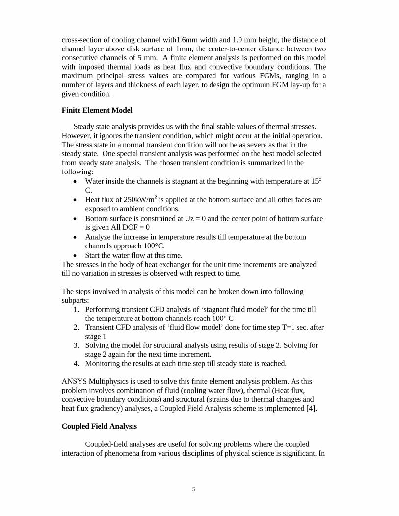
cross-section of cooling channel with1.6mm width and 1.0 mm height, the distance of channel layer above disk surface of 1mm, the center-to-center distance between two consecutive channels of 5 mm. A finite element analysis is performed on this model with imposed thermal loads as heat flux and convective boundary conditions. The maximum principal stress values are compared for various FGMs, ranging in a number of layers and thickness of each layer, to design the optimum FGM lay-up for a given condition. Finite Element Model
Steady state analysis provides us with the final stable values of thermal stresses. However, it ignores the transient condition, which might occur at the initial operation. The stress state in a normal transient condition will not be as severe as that in the steady state. One special transient analysis was performed on the best model selected from steady state analysis. The chosen transient condition is summarized in the following:
• Water inside the channels is stagnant at the beginning with temperature at 15° C.
• Heat flux of 250kW/m2 is applied at the bottom surface and all other faces are exposed to ambient conditions.
• Bottom surface is constrained at Uz = 0 and the center point of bottom surface is given All DOF = 0
• Analyze the increase in temperature results till temperature at the bottom channels approach 100°C.
• Start the water flow at this time. The stresses in the body of heat exchanger for the unit time increments are analyzed till no variation in stresses is observed with respect to time. The steps involved in analysis of this model can be broken down into following subparts:
1. Performing transient CFD analysis of ‘stagnant fluid model’ for the time till the temperature at bottom channels reach 100° C
2. Transient CFD analysis of ‘fluid flow model’ done for time step T=1 sec. after stage 1
3. Solving the model for structural analysis using results of stage 2. Solving for stage 2 again for the next time increment.
4. Monitoring the results at each time step till steady state is reached. ANSYS Multiphysics is used to solve this finite element analysis problem. As this problem involves combination of fluid (cooling water flow), thermal (Heat flux, convective boundary conditions) and structural (strains due to thermal changes and heat flux gradiency) analyses, a Coupled Field Analysis scheme is implemented [4]. Coupled Field Analysis
Coupled-field analyses are useful for solving problems where the coupled interaction of phenomena from various disciplines of physical science is significant. In
6
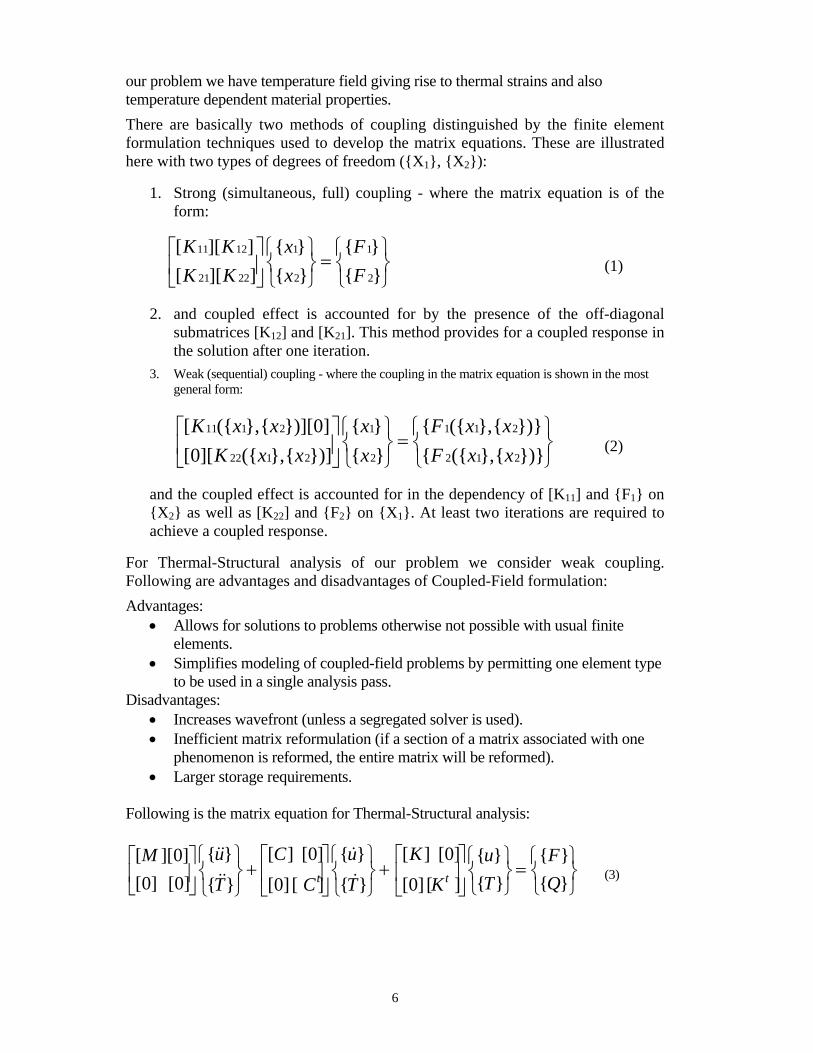
our problem we have temperature field giving rise to thermal strains and also temperature dependent material properties. There are basically two methods of coupling distinguished by the finite element formulation techniques used to develop the matrix equations. These are illustrated here with two types of degrees of freedom ({X1}, {X2}):
1. Strong (simultaneous, full) coupling - where the matrix equation is of the form:
11 12 1 1
21 22 2 2
[ ][ ] { } { }[ ][ ] { } { }K K x FK K x F
⎡ ⎤ ⎧ ⎫ ⎧ ⎫=⎨ ⎬ ⎨ ⎬⎢ ⎥
⎣ ⎦ ⎩ ⎭ ⎩ ⎭ (1)
2. and coupled effect is accounted for by the presence of the off-diagonal submatrices [K12] and [K21]. This method provides for a coupled response in the solution after one iteration.
3. Weak (sequential) coupling - where the coupling in the matrix equation is shown in the most general form:
11 1 2 1 1 1 2
22 1 2 2 2 1 2
[ ({ },{ })][0] { } { ({ },{ })}[0][ ({ },{ })] { } { ({ },{ })}K x x x F x x
K x x x F x x⎡ ⎤ ⎧ ⎫ ⎧ ⎫
=⎨ ⎬ ⎨ ⎬⎢ ⎥⎣ ⎦ ⎩ ⎭ ⎩ ⎭
(2)
and the coupled effect is accounted for in the dependency of [K11] and {F1} on {X2} as well as [K22] and {F2} on {X1}. At least two iterations are required to achieve a coupled response.
For Thermal-Structural analysis of our problem we consider weak coupling. Following are advantages and disadvantages of Coupled-Field formulation: Advantages:
• Allows for solutions to problems otherwise not possible with usual finite elements.
• Simplifies modeling of coupled-field problems by permitting one element type to be used in a single analysis pass.
Disadvantages: • Increases wavefront (unless a segregated solver is used). • Inefficient matrix reformulation (if a section of a matrix associated with one
phenomenon is reformed, the entire matrix will be reformed). • Larger storage requirements.
Following is the matrix equation for Thermal-Structural analysis:
{ } { }[ ] [0] [ ] [0][ ][0] { } { }[0] [0] { } { }{ } [0] [ ] { } [0] [ ]t t
u uC KM u FT QT C T K
⎧ ⎫ ⎡ ⎤ ⎧ ⎫ ⎡ ⎤⎡ ⎤ ⎧ ⎫ ⎧ ⎫+ + =⎨ ⎬ ⎨ ⎬ ⎨ ⎬ ⎨ ⎬⎢ ⎥ ⎢ ⎥⎢ ⎥
⎣ ⎦ ⎩ ⎭ ⎩ ⎭⎩ ⎭ ⎣ ⎦ ⎩ ⎭ ⎣ ⎦
&& &
&& & (3)

7
where [Kt] = [Ktb] + [Ktc]; {F} = {Fnd} + {Fth} + {Fpr} + {Fac} and {Q} = {Qnd} + {Qg} + {Qc} and [K] = Structural stiffness matrix; [Kt] = Thermal conductivity matrix; [Ktb] = Thermal conductivity matrix of material; [Ktc] = Thermal conductivity matrix of convection surface; {F}: Force Vector; {Fnd}: Applied nodal force vector; {Fth}: Thermal strain force vector; {Fpr}: Pressure load vector; {Fac}: Force vector due to acceleration effects (i.e., gravity);{Q}: Heat flow vector; {Qnd}: Applied nodal heat flow rate vector; {Qg}: Heat generation rate vector for causes other than Joule heating; {Qc}: Convection surface vector; [M]: Structural mass matrix; [C]: structural damping matrix; [Ct]: Thermal specific heat matrix; {u}: Displacement vector; {T}: Thermal potential vector Procedure for sequentially coupled-field analysis
As stated before, sequentially coupled (weak form) solving technique is used
for thermal structural analysis. Of the two methods of sequential analysis (indirect, physics environment), the indirect method is implemented. In indirect method, you maintain different databases and results files. Figure 3 shows the data flow for a typical sequential analysis done with the indirect method. Each data base contains the appropriate solid model, elements, loads, etc. You can read information from a results file into another database. Element and node numbers must be consistent between the databases and the results file. For the CFD analysis, 3D Flotran elements were used. Once the CFD analysis is performed the result file is used as a load file for next step. Element type is changed from Flotran to 3D structural elements. Structural constraints are then imposed and model is solved for thermal stresses. For accurate results, variations in the thermal properties of material as well as water are mentioned.
Figure 3: Data Flow for a Sequential Coupled-Field Analysis
Results and discussion
Based on steady state analysis, the maximum principal stress with Model 3 is minimum among the three models. Model 2 gives maximum value of 285 MPa and Model 1 is 213 MPa whereas 168 MPa is for Model 3. These values are for heat flux of 250kW/m2 and bottom clamping constraint and might vary by changing boundary condition and heat flux values. Figures 4 and 5 show maximum principal stress and temperature contours for Model 3 and 2, respectively. Figures 6 and 7 show a comparative graph of variations in stress across thickness for all three models. Based on this comparison study, Model 3 is used for the further case of transient analysis.

8
Figure 4: Maximum Principal Stress Contours: steady state analysis on Model 3
Figure 5: Temperature (K) Contours for steady state analysis of Model 2
-60
-40
-20
0
20
40
60
80
100
0 1 2 3 4 5 6
Height Along Z axis (mm)
Max
imum
Prin
cipa
l Stre
ss
(MP
a)
Model 1Model 2Model 3
Figure 6: Maximum Principal Stresses in FGM models at x = 0, y = 0 mm

9
020406080
100120140160180200
0 1 2 3 4 5 6Height along Z axis (mm)
Max
imum
Prin
cipa
l Stre
ss (M
Pa
Model 1
Model 2
Model 3
Figure 7: Maximum Principal Stresses in FGM models at x = -8.7mm, y = 4.6 mm
Transient Analysis Based on the results from steady state analysis, Model 3 is chosen for transient analysis study. After performing transient CFD analysis with stagnant water, it takes around 15 sec. to heat up bottom channels up to 100° C. After T = 15 sec., water at 15°C starts entering channels with velocity of 0.5 m/s. A fluid-structural sequential analysis was done for each time step of 1 sec after T = 15 sec. It was observed that the stresses start increasing rapidly after the cold water starts flowing through the channels. They reach their maximum value at T = 19 sec. and after that start decreasing and approach the steady state at around T = 26 sec. Figure 8 shows the principal stress contour of the model at T = 19 sec. You can see the stresses going high as 334 MPa, but still below the maximum allowable limit. Figure 9 targets the specific point on the model, which is having the maximum stress value through out the transient case and shows the behavior of that point with respect to time. This point lies on rear bottom left corner of the lower layer channels. The sudden cooling raises the stresses along the body of heat exchanger. And with time these stresses gradually drop down and reach steady state stress values. As this maximum stress value lies below the allowable limit, this model can be considered as safe for this type of transient case.
Figure 8: Maximum Principal Stress Contours at T = 19 sec.

10
0
10
20
30
40
50
60
16 17 18 19 20 21 22 23 24 25 26
Time T (sec.)
Max
imum
Prin
cipa
l Stre
ss (M
Pa)
Figure 9: Maximum Principal Stress plot as a function of time
FABRICATION A major obstacle in fabricating multi-layered FGM discs is to reduce the distortion by process induced residual stresses. A promising result in managing residual stress of two-layered FGMs, made of alumina in one layer and PSZ in the other layer sintered at 1435°C, was presented in [6]. The main problem is that the PSZ powders shrink much more than alumina powder during sintering, resulting the fracture in samples. To resolve this problem, two PSZ powders, each with distinct average particle size, were obtained. Only alumina powder used was TMDAR (the average particle size of 0.2 micron) and Partially Stabilized Zirconia (PSZ) powders include Cerac (the average particle size of 1.2 micron) and TZ3YS(the average particle size of 0.2 micron). Because finer powders can be nested within the interstitial spaces of larger powders, the final shrinkage can be reduced. For the PSZ layer, the ideal mixture of Cerac and TZ-3YS is determined to be 45 volume% and 55 volume% respectively while, for the other layer, the alumina powder is kept to be pure TMDAR. However, the minute curvature could not be further reduced and any additional layer could not be successfully fabricated even after a series of extensive experiments. A new alumina powders (AKP-50) whose average particles size is reported to be between 0.1 and 0.3 microns is used in addition to TMDAR and other Partially Stabilized Zirconia (PSZ) powders include Nanbo and Nanbo-s(both powders have the average particle size of 0.2 micron). It is important to note that the average particle size dose not vary between AKP-50 and TMDAR not to disrupt the shrinkage in the alumina layer. In addition, new strategies are implemented to resolve this problem; (1) mixing two distinct alumina powders (2) sintering at 1475°C. With the higher sintering temperature, a series of experiments has to be repeated to determine the ideal mixture for PSZ. From this experiment, the ideal mixture is found to be 40% Cerac and 60% TZ-3YS with less than 2% difference in height within the sample. Because the TMDAR powder does compact so well, a possibility of using additional alumina powder is considered. However, if a powder with any substantial

11
difference in average particle size is chosen, nesting of smaller powders within larger powders can results in a less shrinkage in the alumina layer. Thus, AKP-50 with the average particle size of 0.2 micron (the same average particle size as TMDAR) is chosen. The mixture of 60% TMDAR/ 40% AKP-50 turns out to be the best mixture that matched the shrinkage of the mixture of 60% TZ3YS/ 40% Cerac. Using such trial-and-error method, three-layer FGMs are also successfully fabricated. The ideal powder combinations are; the alumina layer has 60%TMDAR/ 40% AKP-50, 50/50 mixture 50% TMDAR/ 50% Nanbo-S and finally the PSZ layer 60% TZ3YS/ 40% Cerac. Similarly 6-layered FGMs have been also successfully fabricated as shown in Figure 10. Now we are extending these finding to fabricate different gradiency by controlling the thickness of each layers. The approach taken in this study provide a unique solution to many previous works reporting the residual stress problem in co-sintering multiple layers between zircnonia and alumina [7, 8, 9,10]. Internal channels were formed using a “fugitive compound” added to the ceramic powders before compaction [11]. Among many fugitive phases used (polymers, papers and graphite), graphite is the only fugitive material that successfully introduce internal channels without any damage. For circular channels, pencil leads with nominal diameters of 700, 500 and 300 microns were sectioned into 1 cm to 1.5 cm lengths prior to embedding them in the ceramic power. Prior to pressing, placing the fugitive phase on top of the ceramic powder produces surface or external channels while embedding them in the ceramic powder produces internal channels. The partially sintering is conducted in air for three hours in an electric furnace to burn out the fugitive phase, with an average heating rate of roughly 5ºC per minute to 900ºC, and then a cooling rate of 10ºC per minute. During heating, the specimens were placed on a thin powder bed of the same material as the specimen being sintered. Three layered- FGM with channels has been successfully fabricated as shown in Fig. 11. Even though there are some spots with agglomerations, the sample with channels was flat without any warping or cracks. This sample is similar to the FE models analyzed.
Figure 10: Equal-thickness 6-layered FGM without warping due to residual stress

12
Figure 11: Three-layer FGMs with Channels
TESTING: RESIDUAL STRESS MEASUREMENT In the processing of FGMs, the residual stress has been managed to the point that it does not result in a permanent warping. However, the residual stress does exist in the FGM sample we have fabricated. Residual hoop stress through the thickness of the specimens were measured with the incremental slitting (crack compliance) method [12, 13]. EXPERIMENT Fig. 12 shows the experimental setup. A grinding wheel was used to initially make a diametrical slit 25-µm deep. The diamond grinding wheel was 1.07-mm thick and 152.9-mm in diameter. The wheel was spinning at 3600 RPM, and approximately 1 µm was removed in each pass of the wheel while bathing the cut in coolant. A strain gage had been mounted on the circular face of the specimen opposite the cut to measure the strain in the direction normal to the slit face. A strain reading was taken after the cut. The slit was then deepened in increments of 25-µm, with a strain reading taken after each increment.
Figure 12: The test specimen during the slitting process.

13
The first specimen was cut from the Zirconia side. Data was taken only to a depth of 26% of the specimen thickness, 0.635-mm, because the clamp failed and the specimen cracked. Fig. 13 shows the data. Because the specimen is curved from the same cooling deformations that cause the residual stresses, the strains are plotted versus an average slit depth. After improving the clamping, the second specimen was cut from the Alumina side to about 89% of the specimen thickness. Fig. 14 shows the data from the second slitting test.
Figure 13: Data from first slitting test.
Figure 14: Data from second slitting test.
Analysis Assuming that the stress relaxation was elastic, an elastic inverse problem was used to calculate the original residual stresses [14]. It was assumed that a series expansion of eigenstrains that varied only through-the-thickness of the specimen could represent the residual stresses. Eigenstrains are the incompatible strains that cause residual stresses. For layered materials, using a series of continuous eigenstrains constrains the solution to physically realistic stress discontinuities across interfaces. For practical purposes,
Specimen B
-100
0
100
200
300
400
500
600
700
800
0 0.2 0.4 0.6 0.8 1
non-dimensional slit depth (a/t)
mic
rost
rain Zirconia
MixedlayerAlumina
Specimen A
020406080
100120140160180200
0 0.2 0.4 0.6 0.8 1
non-dimensional slit depth (a/t)
mic
rost
rain
Zirconia AluminaMixedlayer

14
the eigenstrains can be though of as simple thermal strains. A 3D finite element model was used to calculate the strain that would be experimentally measured if the stresses were given by each term in the series expansion. Figure 15 shows the finite element model used for the calculations. Table 1 shows the material properties used in the calculation. The results of the finite element simulation are a matrix of these calibration coefficients. For each slit depth, there is a coefficient (strain) for each term in the series.
Figure 15: The finite element model used to calculate the calibration coefficients for the data
reduction procedure. The color coding shows hoop stress magnitudes, and the model is shown in an intermediate step with the slit at partial depth.
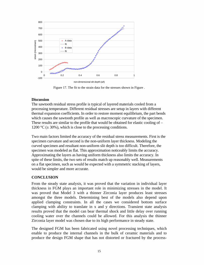
The coefficients in the series expansion are the determined using the calibration coefficients and a least squares fit to best match the measured strains. The order of the expansion is chosen by minimizing the estimated uncertainty [15]. The stresses are then determined by putting the eigenstrain series into the finite element model [14]. Figure 16 shows the resulting stresses and Figure 17 shows the associated fit to the strain data.
Figure 16: Residual hoop stresses measured in the two slitting experiments.
-300
-200
-100
0
100
200
300
0 0.2 0.4 0.6 0.8 1
non-dimensional thickness (z/t)
hoop
stre
ss (M
Pa)
specimen Bspecimen Alayer locations
ZirconiaAlumina Mixedlayer
15
Figure 17. The fit to the strain data for the stresses shown in Figure .
Discussion The sawtooth residual stress profile is typical of layered materials cooled from a processing temperature. Different residual stresses are setup in layers with different thermal expansion coefficients. In order to restore moment equilibrium, the part bends which causes the sawtooth profile as well as macroscopic curvature of the specimen. These results are similar to the profile that would be obtained for elastic cooling of –1200 °C (± 30%), which is close to the processing conditions. Two main factors limited the accuracy of the residual stress measurements. First is the specimen curvature and second is the non-uniform layer thickness. Modeling the curved specimen and resultant non-uniform slit depth is too difficult. Therefore, the specimen was modeled as flat. This approximation noticeably limits the accuracy. Approximating the layers as having uniform thickness also limits the accuracy. In spite of these limits, the two sets of results match up reasonably well. Measurements on a flat specimen, such as would be expected with a symmetric stacking of layers, would be simpler and more accurate. CONCLUSION From the steady state analysis, it was proved that the variation in individual layer thickness in FGM plays an important role in minimizing stresses in the model. It was proved that Model 3 with a thinner Zirconia layer produces least stresses amongst the three models. Determining best of the models also depend upon applied clamping constraints. In all the cases we considered bottom surface clamping with ability to translate in x and y directions. Transient state analysis results proved that the model can bear thermal shock and little delay over running cooling water over the channels could be allowed. For this analysis the thinner Zirconia layer model was chosen due to its high performance in steady state.
The designed FGM has been fabricated using novel processing techniques, which enable to produce the internal channels in the bulk of ceramic materials and to produce the design FGM shape that has not distorted or fractured by the process-
-100
0
100
200
300
400
500
600
700
800
0 0.2 0.4 0.6 0.8 1
non-dimensional slit depth (a/t)
stra
in (m
icro
stra
in) A data
fitB datafit

16
induced residual stress. In addition, the residual stress in the fabricated FGMs has been experimentally measure using crack compliance method. REFERENCES [1] Mori, T., and Tanaka, K., 1973, "Average Stress in Matrix and Average Elastic Energy of Materials
with Misfitting Inclusions," Acta Metallurgica et Materialia, Vol. 21, pp. 571-574 [2] Benveniste, Y., 1987, "A New Approach to the Application of Mori-Tanaka's Theory in Composite
Materials," Mechanics of Materials, Vol.6, pp. 147-157 [3] Kwon, P., Dharan, C. K. H. and Ferrari, M., "Macroscopic Analysis of Axisymmetric Functionally
Gradient materials Under Thermal Loading," Journal of Energy Resources and Technology, 116, (1994), pp. 115-120.
[4] Ansys Theory Reference, Chapter 11. Coupling. [5] Margetts, L., Smith, I., and Leng, J., "Parallel 3D finite element analysis of coupled problems", III
European Conference on Computational Mechanics Solids, Structures and Coupled Problems in Engineering.
[6] Shin, H.Y. , Case, E. and Kwon, P., 2002, “Novel Powder Processing Techniques of Efficient Meso-scale Heat Exchanger,” Transactions of NAMRII, v. XXX, pp. 671-679.
[7] Cai, P. Z., Green, D. J. and Messing, G. L., 1997a, “Constrained Densification of Alumina/Zirconia Hybrid Laminates, I: Experimental Observations of Processing Defects,” J. Am. Ceram. Soc., 80, 8, pp. 1929-1939.
[8] Cai, P. Z., Green, D. J. and Messing, G. L., 1997b, “Constrained Densification of Alumina/Zirconia Hybrid Laminates, II: Viscoelastic Stress Computation,” J. Am. Ceram. Soc., 80, 8, pp. 1940-1948.
[9] Shinagawa, K. and Hirashima, Y., 2003, “Vicoplastic Stress Analysis of Shrinkage and Warping in Graded Layers during Sintering,” Key Engineering Materials, 233-236, pp. 785-790.
[10] Sorenson, B. F., 2002, “Thermally Induced Delamination of Symmetrically Graded Multilayers,” J. Am. Ceram. Soc., 85, 4, pp. 858-864.
[11] Shin, H., Lee, J. G., Kwon, P. and Case, E., "The Fabrication of Smooth, Sub-millimeter Open Channels and Internal Channels in Ceramics and Ceramic Composites without Machining," J. Materials Science Letters, 20, 2, (2001), pp. 107-109. [12] Prime, M. B., 1999, "Residual Stress Measurement by Successive Extension of a Slot: The Crack
Compliance Method " Applied Mechanics Reviews, 52(2), pp. 75-96. [13] Cheng, W., and Finnie, I., 1985, "A Method for Measurement of Axisymmetric Axial Residual
Stresses in Circumferentially Welded Thin-Walled Cylinders," Journal of Engineering Materials and Technology, 107(3), pp. 181-185.
[14] Prime, M. B., and Hill, M. R., 2004, "Measurement of Fiber-Scale Residual Stress Variation in a Metal-Matrix Composite," Journal of Composite Materials, 38(23), pp. 2079-2095.
[15] Prime, M. B., and Hill, M. R., 2006, "Uncertainty, Model Error, and Order Selection for Series-Expanded, Residual-Stress Inverse Solutions," Journal of Engineering Materials and Technology, 128(2), pp. 175-185.