Embed Size (px)
Citation preview

IEICE TRANS. COMMUN., VOL.E96–B, NO.12 DECEMBER 20133153
PAPER
Joint Transmit/Receive MMSE-FDE for Analog Network CodedSingle-Carrier Bi-directional Multi-Antenna Relay
Hiroyuki MIYAZAKI†a), Tatsunori OBARA†, Student Members, and Fumiyuki ADACHI†, Fellow
SUMMARY In this paper, joint transmit/receive frequency-domainequalization (FDE) is proposed for analog network coded (ANC) single-carrier (SC) bi-directional multi-antenna relay. In the proposed scheme,diversity transmission using transmit FDE is performed at relay station(RS) equipped with multiple antennas while receive FDE is carried outat base station (BS) and mobile terminal (MT) both equipped with singleantenna. The transmit and receive FDE weights are jointly optimized soas to minimize the end-to-end mean square error (MSE). We evaluate, bycomputer simulation, the throughput performance and show that the jointtransmit/receive FDE obtains the spatial and frequency diversity gains andaccordingly achieve better throughput performance compared to either thetransmit FDE only or the receive FDE only. It is also shown that ANCSC bi-directional multi-antenna relay can extend the communication cover-age area for the given required throughput compared to conventional directtransmission.key words: analog network coding, single-carrier transmission, jointtransmit/receive frequency-domain equalization
1. Introduction
Next generation mobile communication systems must sup-port broadband data services. However, the throughput ofa user close to the cell edge degrades due to propagationpath loss and shadowing loss. The 2 time-slot cooperativerelay is a promising solution [1]. 2 time-slot cooperative re-lay can reduce the impact of the propagation path loss andthe shadowing loss. However, it requires 4 time-slots forbi-directional communications. Applying network codingto bi-directional relay communications can reduce the re-quired number of time-slots [2]–[5]. There are two typesof network coding: digital network coding (DNC) [2] andanalog network coding (ANC) [3]–[5]. DNC is based on thedecode-and-forward (DF) relaying protocol and can achieve4/3 times higher maximum throughput than conventionalhalf duplex relaying. On the other hand, ANC is based onthe amplify-and-forward relaying protocol and can achieve2 times higher maximum throughput than the conventionalrelaying.
The broadband channel is characterized by frequency-selective fading [6]. Although orthogonal frequency divi-sion multiplexing (OFDM) can overcome the frequency-selective fading [7], it has a drawback of high peak-to-average power ratio (PAPR) and hence, high-performance
Manuscript received January 18, 2013.Manuscript revised July 29, 2013.†The authors are with the Department of Communications En-
gineering, Graduate School of Engineering, Tohoku University,Sendai-shi, 980-8579 Japan.
a) E-mail: [email protected]: 10.1587/transcom.E96.B.3153
amplifiers need to be used [8]. Single-carrier (SC) transmis-sion with minimum mean square error (MMSE) based FDE[9], [10] has an advantage of lower PAPR than OFDM whileexploiting the channel selectivity to improve the through-put. Further throughput improvement is achieved by intro-ducing the joint transmit/receive MMSE-FDE [11]. Alsopromising is the use of multiple antennas at relay sta-tion (RS) [12]–[14]. In [14], the beamforming for bi-directional multi-antenna relay communications was inves-tigated. By employing the beamforming, the spatial di-versity gain can be obtained. However, Ref. [14] assumesnon-frequency-selective fading and focuses on the capacitybound. Therefore, equalization is not considered in [14].In addition to multi-antennal relay, an introduction of jointtransmit/receive FDE may further improve the throughputperformance.
In this paper, we propose a joint transmit/receiveMMSE-FDE for ANC SC bi-directional multi-antenna re-lay. In the proposed scheme, diversity transmission usingtransmit FDE is performed at RS equipped with multipleantennas while receive FDE is carried out at base station(BS) and mobile terminal (MT) both equipped with singleantenna. In ANC relay, RS amplifies and forwards its re-ceived noise to both BS and MT. Since the MT-RS and RS-BS link qualities are different, the noise power forwardedfrom RS is different at BS and MT. As a consequence, thetransmit FDE weight which simultaneously minimizes theuplink and downlink MSEs does not exist. Therefore, inthis paper, we derive the transmit FDE weights optimizedseparately for the uplink (MT to BS) and the downlink (BSto MT). Also, we derive the corresponding receive FDEweights to be used at BS and MT. We evaluate, by computersimulation, the throughput performance and show that thejoint transmit/receive FDE obtains the spatial and frequencydiversity gains and accordingly achieve better throughputperformance compared to either the transmit FDE only orthe receive FDE only. Furthermore, in this paper, we eval-uate the spatial distribution of the throughput and showthat ANC SC bi-directional multi-antenna relay using jointtransmit/receive FDE can extend the communication cover-age compared to conventional direct transmission.
The rest of this paper is organized as follows. Section 2presents the system model and signal representation for theproposed SC ANC bi-directional multi-antenna relay. Sec-tion 3 derives the joint transmit/receive FDE weights. Sec-tion 4 discusses the computer simulation results. Section 5offers some concluding remarks.
Copyright c© 2013 The Institute of Electronics, Information and Communication Engineers

3154IEICE TRANS. COMMUN., VOL.E96–B, NO.12 DECEMBER 2013
Fig. 1 System model.
Fig. 2 ANC protocol.
2. System Model and Signal Representation
2.1 System Model
Figure 1 illustrates the system model of bi-directional multi-antenna relay. The single-cell and single-user environmentis assumed. The cell radius is denoted by dcell. I RSs arelocated entire the cell. The distances between MT and RSa nd between BS and RS are respectively denoted by dM−R
and dB−R. It is assumed that RS is equipped with J antennasand that BS and MT are equipped with single antenna. Theindex of RS selected is denoted by R ∈ {0, 1, . . . , I − 1}.
2.2 Signal Processing of Multi-Antenna ANC
ANC relay requires two time-slots as seen in Fig. 2. In thefirst time-slot, RS receives the superposition of two signalstransmitted simultaneously from BS and MT. In the secondtime-slot, RS carries out diversity transmission after trans-mit FDE to BS and MT. At each of BS and MT, the owntransmitted signal is removed from the received signal andreceive FDE is carried out.
2.3 Signal Representation
In this paper, symbol-spaced discrete-time signal represen-tation is used. Figure 3 shows the transmitter/receiver struc-ture of MT, RS, and BS.
(a) First time-slot
The data symbol blocks of Nc symbols at BS and MT are de-noted as {xB(t) : t=0, . . . ,Nc−1} and {xM(t) : t=0, . . . ,Nc−1},respectively. After insertion of Ng sample cyclic prefix (CP)
Fig. 3 Transmitter/receiver structures of MT, BS and RS.
into the beginning of each block, BS and MT simultane-ously transmit their symbol blocks to RS in the first time-slot. At RS, after CP removal, the received signal is trans-formed into the frequency-domain signal by Nc-point fastFourier transform (FFT). The frequency-domain receivedsignal {YR( j, k) :k=0, . . . ,Nc−1, j=0, . . . , J−1} at jth RSantenna can be expressed as
YR( j, k) =√
2PBd−αB−R10−ηB−R
10 HB−R( j, k)XB(k)
+
√2PMd−αM−R10−
ηM−R10 HM−R( j, k)XM(k) + NR( j, k).
(1)
In Eq. (1), PB and PM are the transmit powers of BS and MT,respectively. HB−R( j, k) and HM−R( j, k) denote the channeltransfer functions between BS and jth RS antenna and be-tween MT and jth RS antenna, respectively. α is the propa-gation path loss exponent. ηB−R and ηM−R denote the shad-owing losses in dB between BS and RS and between MTand RS, respectively. NR( j, k) is the independent zero-meancomplex-valued additive white Gaussian noise (AWGN)having variance 2N0/Ts with N0 and Ts being the single-sided power spectrum density of AWGN and the symbol du-ration, respectively. XB(k) and XM(k) are the transmit signalcomponents at BS and MT, respectively. They are given as⎧⎪⎪⎪⎪⎪⎪⎪⎪⎨⎪⎪⎪⎪⎪⎪⎪⎪⎩
XB(k) =1√Nc
Nc−1∑t=0
xB(t) exp (− j2πkt/Nc)
XM(k) =1√Nc
Nc−1∑t=0
xM(t) exp (− j2πkt/Nc)
. (2)
Equation (1) can be rewritten as
YR( j, k) =√
2PBHB−R( j, k)XB(k)+√
2PM HM−R( j, k)XM(k) + NR( j, k), (3)
where PB = PBd−αcell and PM = PMd−αcell are the normalizedtransmit powers of BS and MT, respectively. HB−R( j, k) and

MIYAZAKI et al.: JOINT TRANSMIT/RECEIVE MMSE-FDE FOR ANALOG NETWORK CODED SINGLE-CARRIER BI-DIRECTIONAL MULTI-ANTENNA RELAY3155
HM−R( j, k) denote the channel transfer functions, includingthe impact of the propagation path loss and the shadowingloss, between BS and RS and between MT and RS, respec-tively. They are given as⎧⎪⎪⎪⎪⎨⎪⎪⎪⎪⎩
HB−R( j, k) = HB−R( j, k)√
r−αB−R10−ηB−R/10
HM−R( j, k) = HM−R( j, k)√
r−αM−R10−ηM−R/10, (4)
where rB−R = dB−R/dcell and rM−R = dM−R/dcell are the nor-malized distances between BS and RS and between MT andRS, respectively.
RS applies FDE to the frequency-domain received sig-nal and amplifies it. The frequency-domain received signal,{YR( j, k) :k=0, . . . ,Nc−1, j=0, . . . , J−1
}, after FDE at jth
RS antenna can be expressed as
YR( j, k) = G( j)YR( j, k)V( j, k), (5)
where V( j, k) denotes the transmit FDE weight at jth RSantenna. The transmit FDE weight has a constraint in orderto keep the average transmit power of RS constant as
1Nc
Nc−1∑k=0
J−1∑j=0
|V( j, k)|2 = 1. (6)
G( j) is the amplifying factor at jth RS antenna. The ampli-fying factor G( j) is set so as to keep the average transmitpower of RS constant as
G( j)=
√2PR
E[|YR( j, k)|2
]=
√√√√√√√√ PR
PM
Nc
Nc−1∑k=0
|HM−R( j, k)|2+ PB
Nc
Nc−1∑k=0
|HB−R( j, k)|2+N
, (7)
where PR = PRd−αcell is the normalized transmit power of RSwith PR denoting the transmit power of RS and N = N0/Ts
is the noise power.
(b) Second time-slot
The equalized frequency-domain signal is transformed backto time-domain signal by Nc-point inverse FFT (IFFT). Af-ter CP insertion, RS broadcasts it to BS and MT in the sec-ond time-slot. At BS and MT receiver, after CP removal,the received signals at BS and MT are transformed into thefrequency-domain signals. The frequency-domain signals,{YB(k) :k=0, . . . ,Nc−1} and {YM(k) :k=0, . . . ,Nc−1}, at BSand MT can be respectively expressed as⎧⎪⎪⎪⎪⎪⎪⎪⎪⎪⎨⎪⎪⎪⎪⎪⎪⎪⎪⎪⎩
YB(k) =J−1∑j=0
HB−R( j, k)YR( j, k) + NB(k)
YM(k) =J−1∑j=0
HM−R( j, k)YR( j, k) + NM(k)
, (8)
where NB(k) and NM(k) are the zero-mean AWGNs at
BS and MT having variance 2N0/Ts, respectively. FromEqs. (3) and (5), Eq. (8) can be rewritten as⎧⎪⎪⎪⎪⎪⎪⎪⎪⎪⎪⎪⎪⎪⎪⎪⎪⎪⎪⎪⎪⎪⎪⎪⎪⎪⎪⎪⎪⎪⎪⎪⎪⎪⎪⎪⎪⎪⎨⎪⎪⎪⎪⎪⎪⎪⎪⎪⎪⎪⎪⎪⎪⎪⎪⎪⎪⎪⎪⎪⎪⎪⎪⎪⎪⎪⎪⎪⎪⎪⎪⎪⎪⎪⎪⎪⎩
YB(k) =√
2PM
J−1∑j=0
G( j)HB−R( j, k)HM−R( j, k)V( j, k)XM(k)
+√
2PB
J−1∑j=0
G( j)HB−R( j, k)HB−R( j, k)V( j, k)XB(k)
+
J−1∑j=0
G( j)HB−R( j, k)V( j, k)NR( j, k) + NB(k)
YM(k)=√
2PB
J−1∑j=0
G( j)HM−R( j, k)HB−R( j, k)V( j, k)XB(k)
+√
2PM
J−1∑j=0
G( j)HM−R( j, k)HM−R( j, k)V( j, k)XM(k)
+
J−1∑j=0
G( j)HM−R( j, k)V( j, k)NR( j, k) + NM(k)
.
(9)
The first and the second term are the desired signal and theown transmitted signal, respectively. The third term is thenoise which is amplified and broadcast by RS. The owntransmitted signal is removed from the received signal as⎧⎪⎪⎪⎪⎪⎪⎪⎪⎪⎪⎪⎪⎪⎪⎨⎪⎪⎪⎪⎪⎪⎪⎪⎪⎪⎪⎪⎪⎪⎩
YB(k) = YB(k)
−√2PB
J−1∑j=0
G( j)HB−R( j, k)HB−R( j, k)V( j, k)XB(k)
YM(k)= YM(k)
−√2PM
J−1∑j=0
G( j)HM−R( j, k)HM−R( j, k)V( j, k)XM(k)
.
(10)
After the own transmitted signal removal, the receiveFDE is carried out. The received signals after re-ceive FDE at BS and MT,
{YB(k) :k=0, . . . ,Nc−1
}and{
YM(k) :k=0, . . . ,Nc−1}, can be respectively given as{
YB(k) = YB(k)WB(k)YM(k) = YM(k)WM(k)
, (11)
where WB(k) and WM(k) are the receive FDE weights atBS and MT receiver, respectively. The equalized signalsare transformed back to the time-domain signal by Nc-pointIFFT, and the data demodulation is carried out.
3. Joint Transmit/Receive MMSE-FDE
The end-to-end MSEs, eu and ed, are respectively definedfor the uplink and downlink as⎧⎪⎪⎪⎪⎪⎪⎪⎪⎨⎪⎪⎪⎪⎪⎪⎪⎪⎩
eu =
Nc−1∑k=0
E[∣∣∣XM(k) − YB(k)
∣∣∣2]
ed =
Nc−1∑k=0
E[∣∣∣XB(k) − YM(k)
∣∣∣2] . (12)

3156IEICE TRANS. COMMUN., VOL.E96–B, NO.12 DECEMBER 2013
From Eqs. (9), (10) and (11), Eq. (12) can be rewritten as⎧⎪⎪⎪⎪⎪⎪⎪⎪⎪⎪⎪⎪⎪⎪⎪⎪⎪⎪⎨⎪⎪⎪⎪⎪⎪⎪⎪⎪⎪⎪⎪⎪⎪⎪⎪⎪⎪⎩
eu =
Nc−1∑k=0
⎡⎢⎢⎢⎢⎢⎢⎢⎢⎢⎢⎢⎢⎢⎢⎣
∣∣∣∣√2PMH(k)WB(k)−1∣∣∣∣2
+2N
⎧⎪⎪⎪⎨⎪⎪⎪⎩J−1∑j=0
|G( j)HB−R( j, k)V( j, k)|2+1
⎫⎪⎪⎪⎬⎪⎪⎪⎭|WB(k)|2
⎤⎥⎥⎥⎥⎥⎥⎥⎥⎥⎥⎥⎥⎥⎥⎦
ed =
Nc−1∑k=0
⎡⎢⎢⎢⎢⎢⎢⎢⎢⎢⎢⎢⎢⎢⎢⎣
∣∣∣∣√2PBH(k)WM(k)−1∣∣∣∣2
+2N
⎧⎪⎪⎪⎨⎪⎪⎪⎩J−1∑j=0
|G( j)HM−R( j, k)V( j, k)|2+1
⎫⎪⎪⎪⎬⎪⎪⎪⎭|WM(k)|2
⎤⎥⎥⎥⎥⎥⎥⎥⎥⎥⎥⎥⎥⎥⎥⎦
,
(13)
where
H(k) =J−1∑j=0
G( j)HB−R( j, k)HM−R( j, k)V( j, k). (14)
From ∂eu/∂WB(k) = 0 and ∂ed/∂WM(k) = 0, the receiveFDE weights at BS and MT are derived as⎧⎪⎪⎪⎪⎪⎪⎪⎪⎪⎪⎪⎪⎪⎪⎪⎪⎪⎨⎪⎪⎪⎪⎪⎪⎪⎪⎪⎪⎪⎪⎪⎪⎪⎪⎪⎩
WB(k) =
√2PMH∗(k)
2PM
∣∣∣H(k)∣∣∣2+2N
⎧⎪⎪⎪⎨⎪⎪⎪⎩J−1∑j=0
|G( j)HB−R( j, k)V( j, k)|2+1
⎫⎪⎪⎪⎬⎪⎪⎪⎭WM(k)=
√2PBH∗(k)
2PB
∣∣∣H(k)∣∣∣2+2N
⎧⎪⎪⎪⎨⎪⎪⎪⎩J−1∑j=0
|G( j)HM−R( j, k)V( j, k)|2+1
⎫⎪⎪⎪⎬⎪⎪⎪⎭
,
(15)
Substituting Eq. (15) to Eq. (13), we obtain⎧⎪⎪⎪⎪⎪⎪⎪⎪⎪⎪⎪⎪⎪⎪⎪⎪⎪⎪⎪⎪⎪⎪⎪⎪⎪⎪⎨⎪⎪⎪⎪⎪⎪⎪⎪⎪⎪⎪⎪⎪⎪⎪⎪⎪⎪⎪⎪⎪⎪⎪⎪⎪⎪⎩
eu =
Nc−1∑k=0
⎧⎪⎪⎪⎨⎪⎪⎪⎩J−1∑j=0
|G( j)HB−R( j, k)V( j, k)|2+1
⎫⎪⎪⎪⎬⎪⎪⎪⎭(PM
N
)−1
∣∣∣H(k)∣∣∣2+⎧⎪⎪⎪⎨⎪⎪⎪⎩
J−1∑j=0
|G( j)HB−R( j, k)V( j, k)|2+1
⎫⎪⎪⎪⎬⎪⎪⎪⎭(PM
N
)−1
ed =
Nc−1∑k=0
⎧⎪⎪⎪⎨⎪⎪⎪⎩J−1∑j=0
|G( j)HM−R( j, k)V( j, k)|2+1
⎫⎪⎪⎪⎬⎪⎪⎪⎭(PB
N
)−1
∣∣∣H(k)∣∣∣2+⎧⎪⎪⎪⎨⎪⎪⎪⎩
J−1∑j=0
|G( j)HM−R( j, k)V( j, k)|2+1
⎫⎪⎪⎪⎬⎪⎪⎪⎭(PB
N
)−1
,
(16)
Below, we derive joint transmit/receive MMSE-FDE for theuplink and the downlink.
3.1 Uplink Transmit and Receive FDE Weights
The optimization problem for obtaining the uplink transmitFDE weight is expressed as
minimize eu
s.t.Nc−1∑k=0
J−1∑j=0
|V( j, k)|2−Nc=0,
|V( j, k)|2≥0, j=0, . . . , J−1, k=0, . . . ,Nc−1
. (17)
By using Caushy-Schwarz inequality [15], eu is satisfied as
eu≤Nc−1∑k=0
{J−1∑j=0|G( j)HB−R( j, k)V( j, k)|2+1
} (PMN
)−1
⎡⎢⎢⎢⎢⎢⎢⎢⎢⎢⎢⎢⎢⎢⎣
(J−1∑j=0|G( j)HB−R( j, k)HM−R( j, k)|2
) (J−1∑j=0|V( j, k)|2
)
+
{J−1∑j=0|G( j)HB−R( j, k)V( j, k)|2+1
} (PMN
)−1
⎤⎥⎥⎥⎥⎥⎥⎥⎥⎥⎥⎥⎥⎥⎦
.
(18)
In Eq. (18), the equality holds if and only if
V(0, k)G(0)H∗B−R(0, k)H∗M−R(0, k)
= . . . =V( j, k)
G( j)H∗B−R( j, k)H∗M−R( j, k)= . . . = P(k)
, (19)
where P(k) the power allocation factor. Substituting Eq. (19)to Eq. (17) gives
minimize eu=
Nc−1∑k=0
{Bu(k)P2(k)+1
}(PM
N
)−1
A2(k)P2(k)+{Bu(k)P2(k)+1
}(PM
N
)−1
s.t.Nc−1∑k=0
A(k)P2(k)−Nc=0,
P2(k)≥0, k=0, . . . ,Nc−1
,
(20)
where⎧⎪⎪⎪⎪⎪⎪⎪⎪⎪⎨⎪⎪⎪⎪⎪⎪⎪⎪⎪⎩
A(k) =J−1∑j=0
|G( j)HM−R( j, k)HB−R( j, k)|2
Bu(k)=J−1∑j=0
|G( j)HM−R( j, k)HB−R( j, k)|2|G( j)HB−R( j, k)|2.
(21)
The optimization problem of Eq. (20) can be solved us-ing Karush-Kuhn-Tucker (KKT) conditions [15]. The La-grangian function F is defined as
F =
⎡⎢⎢⎢⎢⎢⎢⎢⎢⎢⎢⎢⎢⎢⎢⎢⎢⎢⎢⎢⎢⎢⎢⎢⎢⎢⎢⎣
Nc−1∑k=0
{Bu(k)P2(k) + 1
} (PM
N
)−1
A2(k)P2(k) +{Bu(k)P2(k) + 1
} (PM
N
)−1
+λu
⎧⎪⎪⎨⎪⎪⎩Nc−1∑k=0
A(k)P2(k) − Nc
⎫⎪⎪⎬⎪⎪⎭ −Nc−1∑k=0
τ(k)P2(k)
⎤⎥⎥⎥⎥⎥⎥⎥⎥⎥⎥⎥⎥⎥⎥⎥⎥⎥⎥⎥⎥⎥⎥⎥⎥⎥⎥⎦, (22)
where λu and {τ(k) :k=0, . . . ,Nc−1} are the Lagrangianmultipliers, respectively. The optimal power allocation fac-tor P2(k) must satisfy the KKT condition as
∂F∂P2(k)
= 0, (23)
Nc−1∑k=0
A(k)P2(k) − Nc = 0, (24)

MIYAZAKI et al.: JOINT TRANSMIT/RECEIVE MMSE-FDE FOR ANALOG NETWORK CODED SINGLE-CARRIER BI-DIRECTIONAL MULTI-ANTENNA RELAY3157
λu > 0, (25)
P2(k) ≥ 0, (26)
τ(k) ≥ 0, (27)
and
−τ(k)P2(k) = 0. (28)
When τ(k) = 0, P2(k) is obtained from Eqs. (23) and (26) as
P2(k) =1
A(k)
√A(k)λu
(PM
N
)−1
−(PM
N
)−1
A(k) +
(Bu(k)A(k)
) (PM
N
)−1> 0. (29)
On the other hand, when τ(k) > 0, P2(k) is obtained fromEqs. (26) and (28) as
P2(k) = 0. (30)
Therefore, P2(k) is given as
P2(k) = max
⎡⎢⎢⎢⎢⎢⎢⎢⎢⎢⎢⎢⎢⎢⎢⎢⎢⎢⎢⎢⎢⎣1
A(k)
√A(k)λu
(PM
N
)−1
−(PM
N
)−1
A(k) +
(Bu(k)A(k)
) (PM
N
)−1, 0
⎤⎥⎥⎥⎥⎥⎥⎥⎥⎥⎥⎥⎥⎥⎥⎥⎥⎥⎥⎥⎥⎦. (31)
λu is chosen so as to satisfy Eq. (24).Finally, the transmit FDE weight V( j, k) is given from
Eqs. (19) and (31) as
V( j, k)=G( j)H∗M−R( j, k)H∗B−R( j, k)√
A(k)
·
√√√√√√√√√√√√√√√√√max
⎡⎢⎢⎢⎢⎢⎢⎢⎢⎢⎢⎢⎢⎢⎢⎢⎢⎢⎢⎢⎢⎣
√A(k)λu
(PM
N
)−1
−(PM
N
)−1
A(k) +
(Bu(k)A(k)
) (PM
N
)−1, 0
⎤⎥⎥⎥⎥⎥⎥⎥⎥⎥⎥⎥⎥⎥⎥⎥⎥⎥⎥⎥⎥⎦. (32)
Substituting Eq. (32) to Eq. (15), the receive FDE weightWB(k) is obtained.
3.2 Downlink Transmit and Receive FDE Weights
The optimization problem for obtaining the downlink trans-mit FDE weight is expressed as
minimize ed
s.t.Nc−1∑k=0
J−1∑j=0
|V( j, k)|2−Nc=0,
|V( j, k)|2≥0, j=0, . . . , J−1, k=0, . . . ,Nc−1
.
(33)
Similar to the case of uplink, we obtain the downlink trans-mit and receive FDE weights which minimizes the downlinkMSE as
V( j, k)=G( j)H∗M−R( j, k)H∗B−R( j, k)√
A(k)
·
√√√√√√√√√√√√√√√√√max
⎡⎢⎢⎢⎢⎢⎢⎢⎢⎢⎢⎢⎢⎢⎢⎢⎢⎢⎢⎢⎢⎣
√A(k)λd
(PB
N
)−1
−(PB
N
)−1
A(k) +
(Bd(k)A(k)
) (PB
N
)−1, 0
⎤⎥⎥⎥⎥⎥⎥⎥⎥⎥⎥⎥⎥⎥⎥⎥⎥⎥⎥⎥⎥⎦, (34)
where
Bd(k)=J−1∑j=0
|G( j)HM−R( j, k)HB−R( j, k)|2|G( j)HM−R( j, k)|2 .
(35)
and λd is chosen so as to satisfy Eq. (6). SubstitutingEq. (35) to Eq. (15), the receive FDE weight WM(k) is ob-tained.
4. Computer Simulation
The simulation model is illustrated in Fig. 4. I = 6 RSsare located along a circle with radius rB−R = 0.5. The MTlocation is randomly generated in the cell. RS which has thelargest short-term average SNR of MT-RS link is selected as
R = argmaxR′∈(0,1,...,I−1)
⎡⎢⎢⎢⎢⎢⎢⎢⎣PR
Nr−αM−R′10
−ηM−R′
10
⎤⎥⎥⎥⎥⎥⎥⎥⎦ . (36)
The propagation path loss exponent α is assumed to beα = 3.5. The shadowing loss between MT and RS is as-sumed to be characterized by log-normal distribution hav-ing the standard deviation σ = 7.0 dB. The shadowing losscorrelation ρR−R′ between Rth RS-MT link and R′th RS-MTlink is considered. ρR−R′ is assumed to be given as [16]
ρR−R′ = ξ cos θR−R′ + ζ, (37)
where ξ and ζ are the setting parameters ξ ≥ 0, ζ ≥ 0,ξ + ζ ≤ 1. ξ and ζ are set to ξ = ζ = 0.5 in the com-puter simulation. On the other hand, BS-RS link is fixedand hence, the shadowing loss of BS-RS link can be con-trolled by choosing the RS location. The shot-term average
Fig. 4 Simulation model.
3158IEICE TRANS. COMMUN., VOL.E96–B, NO.12 DECEMBER 2013
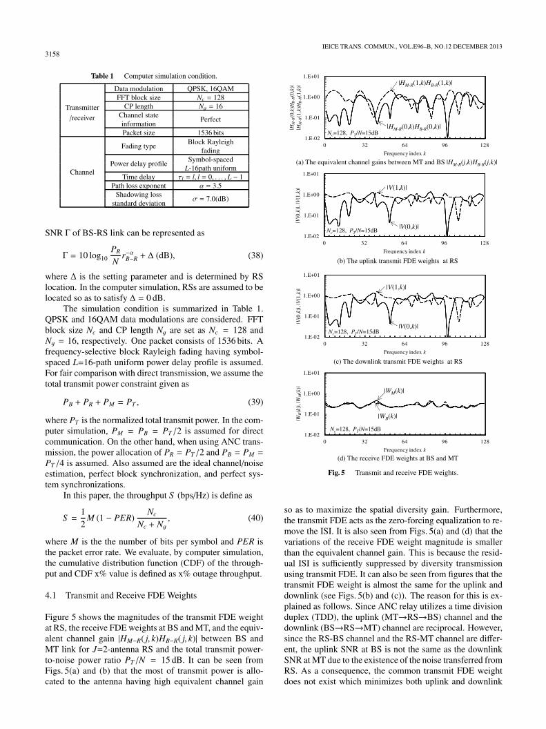
Table 1 Computer simulation condition.
Transmitter
Data modulation QPSK, 16QAM
/receiver
FFT block size Nc = 128CP length Ng = 16
Channel statePerfect
informationPacket size 1536 bits
Channel
Fading typeBlock Rayleigh
fading
Power delay profileSymbol-spaced
L-16path uniformTime delay τl = l, l = 0, . . . , L − 1
Path loss exponent α = 3.5Shadowing loss
σ = 7.0(dB)standard deviation
SNR Γ of BS-RS link can be represented as
Γ = 10 log10PR
Nr−αB−R + Δ (dB), (38)
where Δ is the setting parameter and is determined by RSlocation. In the computer simulation, RSs are assumed to belocated so as to satisfy Δ = 0 dB.
The simulation condition is summarized in Table 1.QPSK and 16QAM data modulations are considered. FFTblock size Nc and CP length Ng are set as Nc = 128 andNg = 16, respectively. One packet consists of 1536 bits. Afrequency-selective block Rayleigh fading having symbol-spaced L=16-path uniform power delay profile is assumed.For fair comparison with direct transmission, we assume thetotal transmit power constraint given as
PB + PR + PM = PT , (39)
where PT is the normalized total transmit power. In the com-puter simulation, PM = PB = PT /2 is assumed for directcommunication. On the other hand, when using ANC trans-mission, the power allocation of PR = PT /2 and PB = PM =
PT /4 is assumed. Also assumed are the ideal channel/noiseestimation, perfect block synchronization, and perfect sys-tem synchronizations.
In this paper, the throughput S (bps/Hz) is define as
S =12
M (1 − PER)Nc
Nc + Ng, (40)
where M is the the number of bits per symbol and PER isthe packet error rate. We evaluate, by computer simulation,the cumulative distribution function (CDF) of the through-put and CDF x% value is defined as x% outage throughput.
4.1 Transmit and Receive FDE Weights
Figure 5 shows the magnitudes of the transmit FDE weightat RS, the receive FDE weights at BS and MT, and the equiv-alent channel gain |HM−R( j, k)HB−R( j, k)| between BS andMT link for J=2-antenna RS and the total transmit power-to-noise power ratio PT /N = 15 dB. It can be seen fromFigs. 5(a) and (b) that the most of transmit power is allo-cated to the antenna having high equivalent channel gain
Fig. 5 Transmit and receive FDE weights.
so as to maximize the spatial diversity gain. Furthermore,the transmit FDE acts as the zero-forcing equalization to re-move the ISI. It is also seen from Figs. 5(a) and (d) that thevariations of the receive FDE weight magnitude is smallerthan the equivalent channel gain. This is because the resid-ual ISI is sufficiently suppressed by diversity transmissionusing transmit FDE. It can also be seen from figures that thetransmit FDE weight is almost the same for the uplink anddownlink (see Figs. 5(b) and (c)). The reason for this is ex-plained as follows. Since ANC relay utilizes a time divisionduplex (TDD), the uplink (MT→RS→BS) channel and thedownlink (BS→RS→MT) channel are reciprocal. However,since the RS-BS channel and the RS-MT channel are differ-ent, the uplink SNR at BS is not the same as the downlinkSNR at MT due to the existence of the noise transferred fromRS. As a consequence, the common transmit FDE weightdoes not exist which minimizes both uplink and downlink

MIYAZAKI et al.: JOINT TRANSMIT/RECEIVE MMSE-FDE FOR ANALOG NETWORK CODED SINGLE-CARRIER BI-DIRECTIONAL MULTI-ANTENNA RELAY3159
mean square errors (MSEs) at the same time. However, themulti-antenna relay (J > 1) improves the received signallevel at both BS and MT in the second time-slot and hence,the impact of transferred noise from RS to both BS and MTcan be made sufficiently weak. If the uplink and downlinkchannels are reciprocal and the transferred noise from RS isnegligible, the common transmit FDE weight exists whichapproximately minimizes both uplink and downlink MSEsat the same time.
4.2 Spatial and Frequency Diversity Gains Achievable byJoint Transmit/Receive FDE
Figure 6 plots the 10% outage throughput performancewhen using ANC transmission with the joint trans-mit/receive MMSE-FDE as a function of the normalizedtransmit power to noise power ratio PT /N. For compar-ison, the performances when using the receive FDE onlyare also plotted in Fig. 6. It is shown from Fig. 6 that thejoint transmit/receive FDE can always provides the through-put performance superior to the receive FDE only. Further-more, the joint transmit/receive MMSE-FDE can improve
Fig. 6 Comparison of the receive FDE only.
the throughput performance as the number of RS antennasincreases while the receive FDE only can hardly improve.This is because the joint transmit/receive MMSE-FDE canobtain the spatial diversity gain while the receive FDE onlycan hardly obtain it. When the number of RS antennas isJ = 4, the joint transmit/receive MMSE-FDE can reduceby about 12 dB the transmit power for the given throughputS=1.6 bps/Hz for both uplink and downlink.
Figure 7 compares the 10% outage throughput perfor-mances when using the joint transmit/receive FDE and thetransmit FDE only. It is shown from Fig. 7 that the jointtransmit/receive MMSE-FDE can improve the throughputperformance compared to the transmit FDE only. This isbecause the joint transmit/receive MMSE-FDE can suppressISI and obtain more frequency diversity gain than the trans-mit FDE only. The performance gap between the joint trans-mit/receive FDE and the transmit FDE only is large whenhigh data modulation level is used. When J = 1, the jointtransmit/receive FDE can reduce by about 4 dB the transmitpower for the given throughput S =1.6 bps/Hz compared tothe transmit FDE only. This is because high data modulation
Fig. 7 Comparison of the transmit FDE only.

3160IEICE TRANS. COMMUN., VOL.E96–B, NO.12 DECEMBER 2013
suffers from the residual ISI and the joint transmit/receiveMMSE-FDE can further suppress the residual ISI comparedto the transmit FDE only.
On the other hand, the performance gap between thejoint transmit/receive FDE and the transmit FDE only re-duce as the number of RS antennas increases. This is be-cause the spatial diversity gain is larger than the frequency-diversity gain.
4.3 Comparison of Direct Transmission
In this subsection, we compare the performances when us-ing multi-antenna ANC transmission and direct transmis-sion and show multi-antenna ANC transmission can reducethe transmit power for the given throughput compared to di-rect transmission.
Figure 8 plots the 10% outage throughput performancewhen using the ANC transmission and direct transmission.It is shown from Fig. 8 that ANC transmission can reduce
Fig. 8 10% outage throughput performance.
the required transmit power compared to direct transmis-sion. Furthermore, multi-antenna ANC transmission can re-duce the transmit power as the number of RS antennas in-creases. This is because multi-antenna ANC transmissionwith the joint transmit/receive MMSE-FDE can mitigate theimpact of the propagation path loss and the shadowing losswith obtaining the spatial diversity gain. When the numberof RS antennas is J = 4, multi-antenna ANC transmissioncan reduce the transmit power by about 23 dB for the giventhroughput S=1.6 bps/Hz.
Figures 9 and 10 show the spatial distribution of 10%outage throughput in the cell. 16QAM data modulation isused and the normalized transmit power to noise power ratioPT /N is set to PT /N = 20 dB. When using direct transmis-sion, the coverage which can achieve the given throughput iscritically limited. When the given 10% outage throughput is1.6 bps/Hz, the normalized radius rcover of the coverage area
Fig. 9 10% outage uplink throughput distribution.
Fig. 10 10% outage downlink throughput distribution.

MIYAZAKI et al.: JOINT TRANSMIT/RECEIVE MMSE-FDE FOR ANALOG NETWORK CODED SINGLE-CARRIER BI-DIRECTIONAL MULTI-ANTENNA RELAY3161
Fig. 11 Average uplink throughput distribution.
limits rcover = 0.3 when using direct transmission. This isbecause the received power drops by the negative impact ofthe propagation path loss and the shadowing loss when MTis located near the cell edge. It is also shown from Fig. 10that single-antenna ANC relay (J=1) can hardly extend thecoverage area for downlink. The reason for this is explainedas follows. In ANC relay, BS-MT direct link is not ex-ploited as the cooperative relay since BS and MT simultane-ously transmit signal in the first time-slot. Therefore, single-antenna ANC relay can obtain no spatial diversity gain, andhence, it suffers from the noise enhancement at RS. There-fore, single-antenna ANC relay can hardly extend the cover-age area. On the other hand, multi-antenna ANC relay withthe joint transmit/receive FDE can obtain the spatial diver-sity gain, and hence, it can significantly extend the coveragearea compared to direct transmission. Multi-antenna ANCtransmission with J=2 can extend the normalized radius ofcoverage area to rcover = 0.8 (rcover = 0.9) for uplink (down-link). It is seen from Figs. 9 and 10 that the performancedifference between uplink and downlink in multi-antennaANC relay (J = 2) is smaller than that in single-antennaANC relay (J = 1). This is because multi-antenna ANCrelay (J > 1) improves the received signal level at both BSand MT and can make the impact of transferred noise fromRS to both BS and MT sufficiently weak.
Figures 11 and 12 show the spatial distribution of theaverage throughput in the cell. 16QAM data modulation isused and the normalized transmit power to noise power ra-tio PT /N is set to PT /N=20 dB. It is shown Figs. 11 and 12that multi-antenna ANC transmission provides higher av-erage throughput than direct transmission all over the cell.When MT is located at the cell edge, multi-antenna ANCtransmission with J=2 can provide 6 times (5 times) higheraverage downlink (uplink) throughput than direct transmis-sion. This is because multi-antenna ANC transmission canachieve the same maximum throughput as direct transmis-sion while mitigating the impact of the propagation path loss
Fig. 12 Average downlink throughput distribution.
and the shadowing loss.
5. Conclusion
In this paper, we proposed a joint transmit/receive MMSE-FDE for ANC bi-directional relay communication using amulti-antenna relay. The proposed scheme performs trans-mit FDE at RS and receive FDE at BS and MT. The trans-mit/receive FDE weight is derived so as to minimize theend-to-end MSE of uplink and downlink. It was shown bythe computer simulation that the joint transmit/receive FDEcan improve the throughput performance compared to eitherthe transmit FDE only or the receive FDE only. It was alsoshown by the computer simulation that multi-antenna SCANC relay with joint transmit/receive FDE can significantlyreduce the transmit power for the given throughput and canextend the coverage area compared to direct transmission.
In this paper, we discussed to what extent the proposedjoint transmit/receive FDE improves the throughput perfor-mance compared to conventional transmission schemes (i.e.,direct transmission and ANC single-antenna relay). Theperformance comparison to physical-layer network coding(PNC) [17] is an interesting future study.
References
[1] J.G. Laneman, D.N.C. Tse, and G.W. Wornell, “Cooperative diver-sity in wireless networks: Efficient protocols and outage behavior,”IEEE Trans. Inf. Theory, vol.50, no.12, pp.3062–3080, Dec. 2004.
[2] S. Katti, H. Pahul, W. Hu, D. Katabi, M. Medard, and J. Crowcroft,“XORs in the air: Practical wireless network coding,” IEEE/ACMTrans. Netw., vol.16, no.2, pp.497–510, June 2008.
[3] S. Katti, S. Gollakota, and D. Katabi, “Embracing wireless interfer-ence: Analog network coding,” Proc. ACM SIGCOMM, pp.397–408, Aug. 2007.
[4] H. Gacanin and F. Adachi, “Broadband analog network coding,”IEEE Trans. Wireless Commun., vol.9, no.5, pp.1577–1783, May2010.
[5] S. Zhang, S.C. Liew, and P.P. Lam, “Hot topic: Physical-layer net-work coding,” Proc. ACM 12th MobiCom 2006, pp.358–365, Sept.

3162IEICE TRANS. COMMUN., VOL.E96–B, NO.12 DECEMBER 2013
2006.[6] J.G. Proakis, Digital Communications, 4th ed., McGraw-Hill, 2001.[7] R. Prasad, OFDM for wireless communications systems, Artech
House, 2004.[8] H. Han and J.H. Lee, “An overview of peak-to-average power ratio
reduction techniques for multicarrier transmission,” IEEE WirelessCommun. Mag., vol.12, no.2, pp.56–65, April 2005.
[9] D. Falconer, S.L. Ariyavistakul, A. Benyamin-Seeyar, and B.Eidson, “Frequency domain equalization for single-carrier broad-band wireless systems,” IEEE Commun. Mag., vol.40, pp.58–66,April 2002.
[10] F. Adachi, H. Tomeba, and K. Takeda, “Introduction of frequency-domain signal processing to broadband single-carrier transmissionsin a wireless channel,” IEICE Trans. Commun., vol.E92-B, no.9,pp.2789–2808, Sept. 2009.
[11] K. Takeda and F. Adachi, “Joint transmit/receive one-tap minimummean square error frequency-domain equalization for broadbandmulticode direct-sequence code division multiple access,” IEEETrans. Signal Process., vol.58, no.10, pp.5463–5468, Oct. 2010.
[12] Y. Liang, A. Ikhlef, W. Gerstacker, and R. Schober, “Filter-and-forward beamforming for multiple multi-antenna relays,” Proc. CHI-NACOM, 2010 5th International ICST Conference, pp.1–8, Aug.2010.
[13] R. Zhang, C.C. Chai, Y.C. Liang, and S. Cui, “On capacity regionof two-way multi-antenna relay channel with analogue network cod-ing,” Proc. IEEE Intern. Conf. on Commun., pp.1–5, June 2009.
[14] R. Zhang, Y.C. Liang, C.C. Chai, and S. Cui, “Optimal beamform-ing for two-way multi-antenna relay channel with analogue networkcoding,” IEEE J. Sel. Areas Commun., vol.27, no.5, pp.699–712,June 2009.
[15] S. Boyd and L. Vandenberghe, Convex optimization, CambridgeUniversity Press, 2003.
[16] S.S. Szyszkowicz, H. Yanikomeroglu, and J.S. Thompson, “On thefeasibility of wireless shadowing correlation models,” IEEE Trans.Veh. Technol., vol.59, no.9, pp.4222–4236, Nov. 2010.
[17] H.H. Chung, S.H. Kuo, and M.C. Lin, “A physical-layer networkcoding scheme based on linear MIMO detection,” Proc. IEEE 75thVehicular Tech. Conf. (VTC), pp.1–5, May 2013.
[18] H. Miyazaki, M. Nakada, T. Obara, and F. Adachi, “Joint trans-mit/receive MMSE-FDE for MIMO analog network coding insingle-carrier bi-directional relay communications,” Proc. IEEE 71stVehicular Tech. Conf. (VTC), pp.1–5, Sept. 2012.
Hiroyuki Miyazaki received his B.S. degreein Information and Intelligent Systems from To-hoku University, Sendai Japan, in 2011. Cur-rently he is a graduate student at the Depart-ment of Communications Engineering, Grad-uate School of Engineering, Tohoku Univer-sity. His research interests include cooperativeamplify-and-forward relay and network codingsystems.
Tatsunori Obara received his B.S. de-gree in Electrical, Information and Physics En-gineering in 2008 and M.S. degree in communi-cations engineering, in 2010, respectively, fromTohoku University, Sendai Japan. Currently heis a Japan Society for the Promotion of Sci-ence (JSPS) research fellow, studying towardhis PhD degree at the Department of Electri-cal and Communications Engineering, GraduateSchool of Engineering, Tohoku University. Hisresearch interests include channel equalization
techniques for mobile communication systems.
Fumiyuki Adachi received the B.S. andDr. Eng. degrees in electrical engineering fromTohoku University, Sendai, Japan, in 1973 and1984, respectively. In April 1973, he joined theElectrical Communications Laboratories of Ni-ppon Telegraph & Telephone Corporation (nowNTT) and conducted various types of researchrelated to digital cellular mobile communica-tions. From July 1992 to December 1999, hewas with NTT Mobile Communications Net-work, Inc. (now NTT DoCoMo, Inc.), where he
led a research group on wideband/broadband CDMA wireless access forIMT-2000 and beyond. Since January 2000, he has been with Tohoku Uni-versity, Sendai, Japan, where he is a distinguished Professor of Communi-cations Engineering at the Graduate School of Engineering. His researchinterest is in the areas of wireless signal processing and networking in-cluding broadband wireless access, equalization, transmit/receive antennadiversity, MIMO, adaptive transmission, channel coding, etc. He was aprogram leader of the 5-year Global COE Program “Center of Educationand Research for Information Electronics Systems” (2007–2011), awardedby the Ministry of Education, Culture, Sports, Science and Technology ofJapan. From October 1984 to September 1985, he was a United KingdomSERC Visiting Research Fellow in the Department of Electrical Engineer-ing and Electronics at Liverpool University. He is an IEICE Fellow and wasa co-recipient of the IEICE Transactions best paper of the year award 1996,1998, and 2009 and also a recipient of Achievement award 2003. He is anIEEE Fellow and a VTS Distinguished Lecturer for 2011 to 2013. He wasa co-recipient of the IEEE Vehicular Technology Transactions best paperof the year award 1980 and again 1990 and also a recipient of Avant Gardeaward 2000. He was a recipient of Thomson Scientific Research FrontAward 2004, Ericsson Telecommunications Award 2008, Telecom SystemTechnology Award 2009, and Prime Minister Invention Prize 2010.