Embed Size (px)
Citation preview
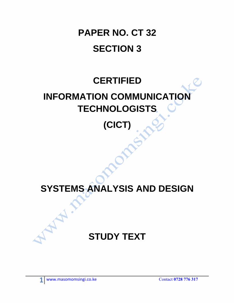
PAPER NO. CT 32
SECTION 3
CERTIFIED
INFORMATION COMMUNICATION
TECHNOLOGISTS
(CICT)
SYSTEMS ANALYSIS AND DESIGN
STUDY TEXT
1 www.masomomsingi.co.ke Contact 0728 776 317
KASNEB SYLABUSS
SYSTEMS ANALYSIS AND DESIGN
GENERAL OBJECTIVE
This paper is intended to equip the candidate with the knowledge, skills and attitude that will enable him/her analyse and design information systems
LEARNING OUTCOMES
A candidate who passes this paper should be able to:
Assess the need for an information system in an organisation
Use conventional methodologies in systems analysis and design
Comply with applicable standards in systems analysis and design
implement information systems in an organisation
CONTENT
1. Introduction to systems analysis and design
Systems theory
Types of information systems
Role of the systems analyst and user departments
Systems analysis concepts
2. Systems thinking
Hard systems thinking
Soft systems thinking
Soft systems methodology
Hard systems methodology
Applications of soft and hard systems
3. Systems development life cycle (SDLC)
Definition of systems development life cycle Phases
4. Structured systems analysis and design methodology (SSADM)
SSADM stages Strengths and limitations of SSADM SSADM Modeling techniques
5. Alternative systems approaches and methods
Rapid application development (RAD) Joint application development (JAD)
Object-oriented design methodologies: UML. class, sequence and use case diagrams
Other system development approaches
2 www.masomomsingi.co.ke Contact 0728 776 317
6. Systems analysis
The need to initiate an information systems project
Stages and tools in systems analysis
Fact finding techniques
Feasibility study
The analysis report
7. Systems design
Logical and physical design Systems design approaches
Writing design specifications
8. Systems analysis and design standards
Roles and examples of standards in SAD projects Components and development of documentation in a systems project
Challenges in meeting standards in SAD projects
9. Systems implementation
Assessing the platform for the system to be implemented
Changeover/conversion methods
Forms of testing
User training
10. Systems analysis and design environment
Security requirements, precautions and procedures in SAD Procedures for maintenance of a system
integration challenges of system projects with existing systems
11. Emerging issues and trends
CONTENT PAGE
Chapter 1: Introduction to systems analysis and design……………………………………………4 Chapter 2: Systems thinking ………………………………………………………………….…...19 Chapter 3: Systems development life cycle (SDLC)……………………………………………….25 Chapter 4: Structured systems analysis and design methodology (SSADM)………………………27 Chapter 5: Alternative systems approaches and methods….……………………………….………34 Chapter 6: Systems analysis……….………………………………………………………..………49 Chapter 7: Systems design...…………………………………………………………………..…….63 Chapter 8: Systems analysis and design standards………………………………………………….86 Chapter 9: Systems implementation…………………………………………………………………97 Chapter 10: Systems analysis and design environment………………………………………….....109
Chapter 11: Emerging issues and trends
3 www.masomomsingi.co.ke Contact 0728 776 317
CHAPTER 1
INTRODUCTION TO SYSTEM ANALYSIS AND DESIGN
CONCEPT OF SYSTEM THEORY
It is essential to understand the concept of system theory as it relates to business as well as the
design of business systems and particularly serve as useful way of describing and analyzing
computer systems. A business is an example of an organizational system where economic
resources (input) are transformed by various businesses (processing) into goods and services
(output). Information systems provide information (feedback) on the operations of the system to
management for the direction and maintenance of the system (control) as it exchanges inputs and
outputs with its environment.
Let me briefly explain the following important subheading in context of system theory:
1. System environment 2. System boundary 3. Feedback and Control
SYSTEM ENVIRONMENT: System exists and functions in an environment containing other
system. The external environment surrounds the system and is not part of it, while the system
boundary separates the system from its external environment. The line between the system and
its external environment is the boundary. Systems are affected to different degrees and in
various ways by their external environment. Inputs come from and output is transferred to the
external environment of a system.
SYSTEM BOUNDARY: Every system has a boundary that separates it from its external
environment. The boundary delineates the scope of a system and serves three main purposes:
it encloses the system activities
it demarcates the system from other systems in the external environment and it reflects the system objectives.
The constraints or features which define a system are its boundaries and many practical
problems are related to alteration in boundaries. System boundaries may be natural or artificially
created. For example, an organization's departmental structures are artificially created.
4 www.masomomsingi.co.ke Contact 0728 776 317
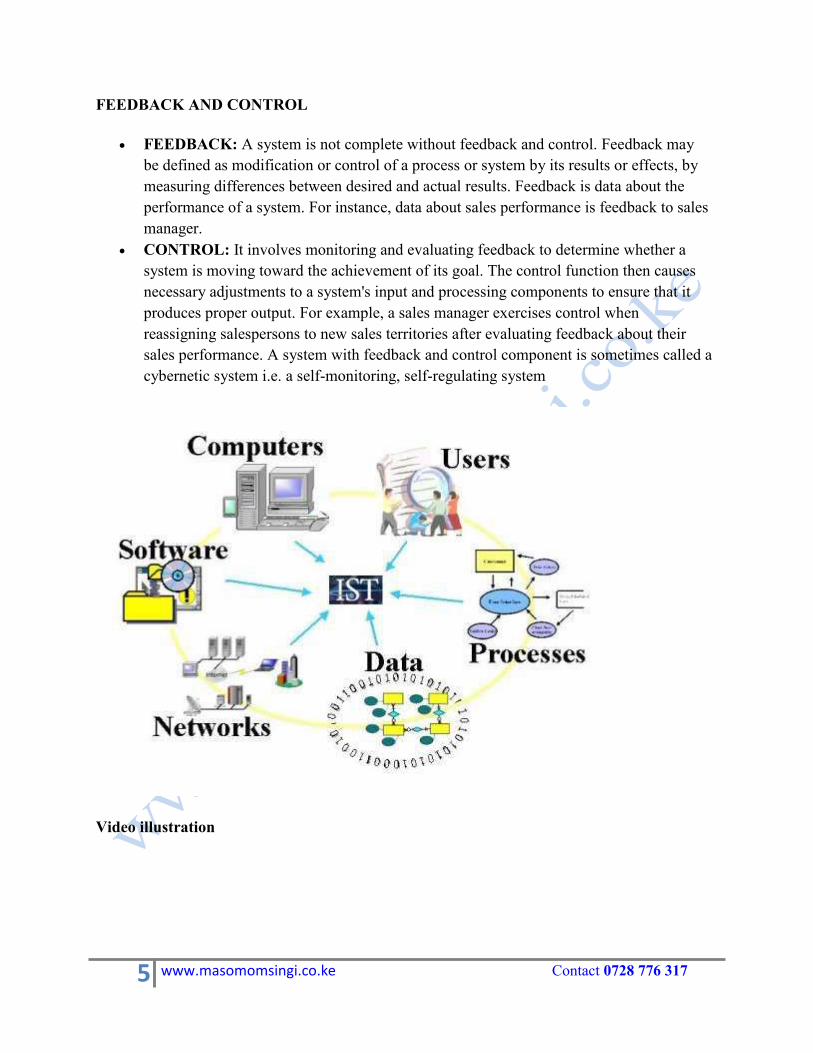
FEEDBACK AND CONTROL
FEEDBACK: A system is not complete without feedback and control. Feedback may
be defined as modification or control of a process or system by its results or effects, by
measuring differences between desired and actual results. Feedback is data about the
performance of a system. For instance, data about sales performance is feedback to sales
manager.
CONTROL: It involves monitoring and evaluating feedback to determine whether a
system is moving toward the achievement of its goal. The control function then causes
necessary adjustments to a system's input and processing components to ensure that it
produces proper output. For example, a sales manager exercises control when
reassigning salespersons to new sales territories after evaluating feedback about their
sales performance. A system with feedback and control component is sometimes called a
cybernetic system i.e. a self-monitoring, self-regulating system
Video illustration
5 www.masomomsingi.co.ke Contact 0728 776 317
SYSTEM LIFE CYCLE
System life cycle is an organizational process of developing and maintaining systems. In the
system `Analysis and Design terminology, the SDLC mean software developed life cycle.
The methodology SDLC is closely linked to what has come to be known as structured
systems analysis & design. It involves a series of steps to be undertaking in the development
if information system as follows:
SYSTEM STUDY (problem definition)
FEASIBILITY STUDY
SYSTEM ANALYSIS
SYSTEM DESIGN
CODING (system construction)
TESTING and EVALUATION
IMPLEMENTATION MAINTENANCE
SYSTEM STUDY (problem definition):System study is the first stage of system development
life cycle. On receiving a request from the user for system development, an investigation is
conducted to state the problem to be solved. This gives a clear picture of what actually the
physical system is? In practice, the system study is done in two phases; the preliminary survey of
the system is done which helps in identifying scope of the system. The second phase of the
system study is more detailed and in-depth study in which the identification of user's
requirement and the limitations and problem of the present system are studied
To describe the system study phase more analytically, we would say that system study phase
passes through the following steps:
problem identification and project initiation
background analysis inference or findings
FEASIBILITY STUDY: On the basis of result of the initial study, feasibility study takes place.
The feasibility study is basically the test of the proposed system in the light of its workability,
meeting user's requirements, effective use of resources and of course, the cost effectiveness. The
main goal of feasibility study is not to solve the problem but to achieve scope and objectives of the
system project, and to identify alternative solution to the problem defined earlier. In the process of
feasibility study, the cost and benefit are estimated with greater accuracy.
Deliverable: Feasibility report
6 www.masomomsingi.co.ke Contact 0728 776 317
SYSTEM ANALYSIS: Assuming that a new system is to be developed, the next phase is
system analysis. Analysis involved a detailed study of the current system, leading to
specifications of a new system. Analysis is a detailed study of various operations performed by
a system and their relationships within and outside the system. During analysis data are
collected on the available files, decision point and transaction handled by the present system.
That is the present system is investigated and its specifications documented. They should
contain out understanding f how the present system works and what it does.
TYPES OF INFORMATION SYSTEMS
An information system is a collection of hardware, software, data, people and procedures that
are designed to generate information that supports the day-to-day, short-range, and long-range
activities of users in an organization. Information systems generally are classified into five
categories: office information systems, transaction processing systems, management information
systems, decision support systems, and expert systems. The following sections present each of
these information systems.
1. Office Information Systems
An office information system, or OIS (pronounced oh-eye-ess), is an information system that
uses hardware, software and networks to enhance work flow and facilitate communications
among employees. With an office information system, also described as office automation;
employees perform tasks electronically using computers and other electronic devices, instead of
manually. With an office information system, for example, a registration department might post
the class schedule on the Internet and e-mail students when the schedule is updated. In a manual
system, the registration department would photocopy the schedule and mail it to each student‘s
house.
An office information system supports a range of business office activities such as creating
and distributing graphics and/or documents, sending messages, scheduling, and accounting.
All levels of users from executive management to non-management employees utilize and
benefit from the features of an OIS.
The software an office information system uses to support these activities include word
processing, spreadsheets, databases, presentation graphics, e-mail, Web browsers, Web page
authoring, personal information management, and groupware. Office information systems use
communications technology such as voice mail, facsimile (fax), videoconferencing, and
electronic data interchange (EDI) for the electronic exchange of text, graphics, audio, and video.
7 www.masomomsingi.co.ke Contact 0728 776 317
An office information system also uses a variety of hardware, including computers equipped
with modems, video cameras, speakers, and microphones; scanners; and fax machines.
2. Transaction Processing Systems
A transaction processing system (TPS) is an information system that captures and processes
data generated during an organization‘s day-to-day transactions. A transaction is a business
activity such as a deposit, payment, order or reservation.
Clerical staffs typically perform the activities associated with transaction processing, which
include the following:
1. Recording a business activity such as a student‘s registration, a customer‘s order, an
employee‘s timecard or a client‘s payment. 2. Confirming an action or triggering a response, such as printing a student‘s schedule,
sending a thank-you note to a customer, generating an employee‘s paycheck or
issuing a receipt to a client. 3. Maintaining data, which involves adding new data, changing existing data, or
removing unwanted data
Transaction processing systems were among the first computerized systems developed to process
business data – a function originally called data processing. Usually, the TPS computerized an
existing manual system to allow for faster processing, reduced clerical costs and improved
customer service.
The first transaction processing systems usually used batch processing. With batch processing,
transaction data is collected over a period of time and all transactions are processed later, as a
group. As computers became more powerful, system developers built online transaction
processing systems. With online transaction processing (OLTP) the computer processes
transactions as they are entered. When you register for classes, your school probably uses
OLTP. The registration administrative assistant enters your desired schedule and the computer
immediately prints your statement of classes. The invoices, however, often are printed using
batch processing, meaning all student invoices are printed and mailed at a later date
Today, most transaction processing systems use online transaction processing. Some routine
processing tasks such as calculating paychecks or printing invoices, however, are performed
more effectively on a batch basis. For these activities, many organizations still use batch
processing techniques.
8 www.masomomsingi.co.ke Contact 0728 776 317
3. Management Information Systems
While computers were ideal for routine transaction processing, managers soon realized that the
computers‘ capability of performing rapid calculations and data comparisons could produce
meaningful information for management. Management information systems thus evolved out of
transaction processing systems. A management information system, or MIS (pronounced em-
eye-ess), is an information system that generates accurate, timely and organized information so
managers and other users can make decisions, solve problems, supervise activities, and track
progress. Because it generates reports on a regular basis, a management information system
sometimes is called a management reporting system (MRS).
Management information systems often are integrated with transaction processing systems. To
process a sales order, for example, the transaction processing system records the sale, updates
the customer‘s account balance, and makes a deduction from inventory. Using this information,
the related management information system can produce reports that recap daily sales activities;
list customers with past due account balances; graph slow or fast selling products; and highlight
inventory items that need reordering. A management information system focuses on generating
information that management and other users need to perform their jobs.
An MIS generates three basic types of information: detailed, summary and exception. Detailed
information typically confirms transaction processing activities. A Detailed Order Report is an
example of a detail report. Summary information consolidates data into a format that an
individual can review quickly and easily. To help synopsize information, a summary report
typically contains totals, tables, or graphs. An Inventory Summary Report is an example of a summary report.
Exception information filters data to report information that is outside of a normal condition.
These conditions, called the exception criteria, define the range of what is considered normal
activity or status. An example of an exception report is an Inventory Exception Report is an
Inventory Exception Report that notifies the purchasing department of items it needs to reorder.
Exception reports help managers save time because they do not have to search through a
detailed report for exceptions. Instead, an exception report brings exceptions to the manager‘s
attention in an easily identifiable form. Exception reports thus help them focus on situations that
require immediate decisions or actions.
4. Decision Support Systems
Transaction processing and management information systems provide information on a regular
basis. Frequently, however, users need information not provided in these reports to help them
make decisions. A sales manager, for example, might need to determine how high to set yearly
9 www.masomomsingi.co.ke Contact 0728 776 317
THIS IS A SAMPLE
SOFT HARD COPYCOMPLETE NOTES ARE IN AND IN
0728 776 317CALL|TEXT|WHATSAPP
OR
[email protected] Email:
CHAPTER 2
SYSTEMS THINKING
Hard and Soft System Methodologies: The Differences
A System Thinking uses a variety of techniques that may be divided into hard systems and soft
systems.
Hard systems (HS) involves simulations, often using computers and the techniques used in
operations research. Hard systems look at the ―How?‖ meaning, how to best achieve and test
the selected option of development and analysis. Hard systems methodologies are useful for
problems that can justifiably be quantified. However, it cannot easily take into account
unquantifiable variables (opinions, culture, politics, etc.), and may treat people as being passive,
rather than having complex motivations.
HS have an explicit objective governed by fixed rules such as those encountered in
decision making.
Operational Research is a hard, well defined system. Examples of areas that apply hard
systems methodology are:
• Project Management • Forecasting • Simulation • Mathematical Programming • Decision Theory
Another characteristic of hard systems that it is:
• Stochastic – Statistically based on probability. • Deterministic – fixed inputs and known outputs
Soft systems methodologies (SSM) are used to tackle systems that cannot easily be quantified,
especially those involving people interacting with each other or with "systems". Useful for
understanding motivations, viewpoints, and interactions but, naturally, it doesn't give quantified
answers. Soft Systems are a field that the academic Peter Checkland has done much to develop.
Soft systems looks at the ―What?‖ of the system; What to do to achieve an improvement,
Usually analysis before application or implementation
THIS IS A SAMPLE
SOFT HARD COPYCOMPLETE NOTES ARE IN AND IN
0728 776 317CALL|TEXT|WHATSAPP
OR
[email protected] Email:
CHAPTER 3
SYSTEMS DEVELOPMENT LIFE CYCLE (SDLC)
Definition of systems development life cycle
The systems development life cycle (SDLC), also referred to as the application
development life-cycle, is a term used in systems engineering, information systems and
software engineering to describe a process for planning, creating, testing, and deploying
an information system. The systems development life-cycle concept applies to a range of
hardware and software configurations, as a system can be composed of hardware only,
software only, or a combination of both.
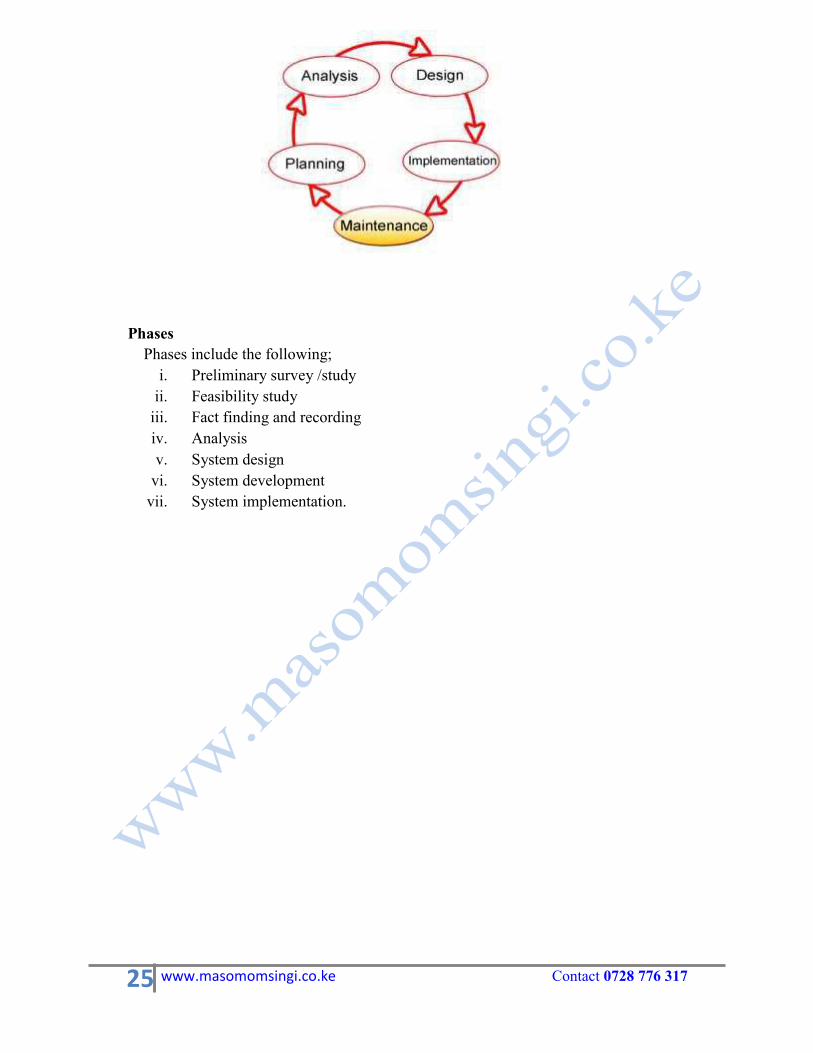
Phases Phases include the following;
i. Preliminary survey /study
ii. Feasibility study iii. Fact finding and recording iv. Analysis v. System design
vi. System development vii. System implementation.
25 www.masomomsingi.co.ke Contact 0728 776 317
CHAPTER 4
STRUCTURED SYSTEMS ANALYSIS AND
DESIGN METHODOLOGY (SSADM)
Structured systems analysis and design method (SSADM) (originally released as
methodology) is a systems approach to the analysis and design of information systems. SSADM
was produced for the Central Computer and Telecommunications Agency (now Office of
Government Commerce), a UK government office concerned with the use of technology in
government, from 1980 onwards. SSADM is a waterfall method for the analysis and design of information systems. SSADM can
be thought to represent a pinnacle of the rigorous document-led approach to system design,
and contrasts with more contemporary agile methods such as DSDM or Scrum. SSADM is one particular implementation and builds on the work of different schools of
structured analysis and development methods, such as Peter Checkland'ssoft systems
methodology, Larry Constantine's structured design, Edward Yourdon's Yourdon Structured
Method, Michael A. Jackson's Jackson Structured Programming, and Tom DeMarco's
structured analysis. The names "Structured Systems Analysis and Design Method" and "SSADM" are
registered trademarks of the Office of Government Commerce (OGC), which is an office of
the United Kingdom's Treasury.[1]
STAGES AND CONTENT
Stages
The SSADM method involves the application of a sequence of analysis, documentation
and design tasks concerned with the following. Stage 0 – Feasibility study
In order to determine whether or not a given project is feasible, there must be some form of
investigation into the goals and implications of the project. For very small scale projects this
may not be necessary at all as the scope of the project is easily understood. In larger projects, the
feasibility may be done but in an informal sense, either because there is not time for a formal
study or because the project is a ―must-have‖ and will have to be done one way or the other.
27 www.masomomsingi.co.ke Contact 0728 776 317
THIS IS A SAMPLE
SOFT HARD COPYCOMPLETE NOTES ARE IN AND IN
0728 776 317CALL|TEXT|WHATSAPP
OR
[email protected] Email:
CHAPTER 5
ALTERNATIVES SYSTEM APPROACHES AND METHODS
Rapid application development (RAD)
Rapid application development (RAD) is a software development methodology that uses
minimal planning in favor of rapid prototyping. The "planning" of software developed using
RAD is interleaved with writing the software itself. The lack of extensive pre-planning generally
allows software to be written much faster, and makes it easier to change requirements
History
Rapid Application Development (RAD) is a term originally used for describing a software
development process first developed and successfully deployed during the mid-1970s by the
New York Telephone Co's Systems Development Center under the direction of Dan Gielan.
Following a series of remarkably successful implementations of this process, Gielan lectured
extensively in various forums on the methodology, practice, and benefits of this process.
RAD involves iterative development and the construction of prototypes. In 1990, in his book RAD,
Rapid Application Development, James Martin documented his interpretation of the methodology.
More recently, the term and its acronym have come to be used in a broader, general sense that
encompasses a variety of methods aimed at speeding application development, such as the use of
software frameworks of varied types, such as web application frameworks.
Rapid application development is a response to processes developed in the 1970s and 1980s,
such as the Structured Systems Analysis and Design Method and other Waterfall models.
One problem with previous methodologies was that applications took so long to build that
requirements had changed before the system was complete, resulting in inadequate or even unusable systems. Another problem was the assumption that a methodical requirements analysis
phase alone would identify all the critical requirements. Ample evidence[citation needed]
attests to the fact that this is seldom the case, even for projects with highly experienced professionals at all
levels.
Starting with the ideas of Brian Gallagher, Alex Balchin, Barry Boehm and Scott Shultz,
James Martin developed the rapid application development approach during the 1980s at IBM
and finally formalized it by publishing a book in 1991, Rapid Application Development. Four phases of RAD
1. Requirements Planning phase – combines elements of the system planning and
systems analysis phases of the Systems Development Life Cycle (SDLC). Users,
managers, and IT staff members discuss and agree on business needs, project scope,
constraints, and system requirements. It ends when the team agrees on the key issues and
obtains management authorization to continue. 2. User design phase – during this phase, users interact with systems analysts and develop
models and prototypes that represent all system processes, inputs, and outputs. The RAD
groups or subgroups typically use a combination of Joint Application Development
(JAD) techniques and CASE tools to translate user needs into working models. User
Design is a continuous interactive process that allows users to understand, modify, and
eventually approve a working model of the system that meets their needs. 3. Construction phase – focuses on program and application development task similar to
the SDLC. In RAD, however, users continue to participate and can still suggest
changes or improvements as actual screens or reports are developed. Its tasks are
programming and application development, coding, unit-integration and system testing. 4. Cutover phase – resembles the final tasks in the SDLC implementation phase, including
data conversion, testing, changeover to the new system, and user training. Compared
with traditional methods, the entire process is compressed. As a result, the new system is
built, delivered, and placed in operation much sooner.
Relative effectiveness
The shift from traditional session-based client/server development to open sessionless and
collaborative development like Web 2.0 has increased the need for faster iterations through
the phases of the software development process.[1]
This, coupled with the growing use of
open source frameworks and products in core commercial development, has, for many
developers, rekindled interest in finding a silver bullet RAD methodology.
Rapid Application Development (RAD) can be considered as a type of Agile technique or vice-a-
versa. Some may, however, choose to separate these two based on the fact that RAD focuses on
developing what is interesting instead of what is needed, as in conventional Agile. But it can be
argued that end users are eventually going to need what interests them, thus making it hard to
differentiate between the two methodologies.
Although most RAD methodologies foster software re-use, small team structure and distributed
system development, most RAD practitioners recognize that, ultimately, no one "rapid"
methodology can provide an order of magnitude improvement over any other development
methodology.
THIS IS A SAMPLE
SOFT HARD COPYCOMPLETE NOTES ARE IN AND IN
0728 776 317CALL|TEXT|WHATSAPP
OR
[email protected] Email:
CHAPTER 6
SYSTEMS ANALYSIS
The need to initiate an information systems project
Companies often commit significant resources to develop, acquisition and continued
maintenance of application systems. These systems often controls an organizations assets
and mayin themselves be considered an asset that to be protected and controlled.
One or more of the following situations will initiate an individual application or project,
a) A new opportunity that relate to an actual business process b) A new problem that relates to an actual business process c) A new opportunity that will enable the organization to take advantage of technology d) A problem with the current technology e) Organization growth f) Merger or acquisition g) Revision in government regulations
System development projects should be initiated using well defined procedures to
communicate business needs to management. These procedures often require detailed
documentation identifying the need or problem, specifying the desired solutions and relating
the potential benefits to the organization.
Aid in system analysis and design include
a) Methodologies – comprehensive, multi-step approach to systems development that
guides the work and influences the quality of the final product. b) Techniques-i.e. a particular process to be followed by every one c) Tools- computer programs that make it easier to use and benefit from techniques and to
faithfully follow the guidelines of the overall development methodology.
STAGES AND TOOLS IN SYSTEM ANALYSIS
Six phases of system development life cycle: A ―system‖ is defined as a collection of related components that interact to perform a task in
order to accomplish a goal. The point of system analysis & design is to ascertain how a system
works and then take steps to make it better. A ―system Analyst‖ is an information specialist who performs system analysis, design, and
implementation.
Six phases of System Analysis & Design: - This is a six-phase problem solving procedure for examining an information system and
improving it. ―The SDLC, system development life cycle is defined as the step-by-step process
that many organizations follow during system analysis and design.
Preliminary investigation System analysis System design System development System implementation System maintenance
First phase: conduct a preliminary investigation: - The objective of phase 1, preliminary investigation, is to conduct a preliminary analysis
Purpose alternative solutions, describe costs and benefits and submit preliminary plan -
recommendations. In this first phase again we have four steps those are: -
Conduct preliminary analysis Propose alternative solutions. Describe costs and benefits of each solutions Submit preliminary plan with recommendations.
1. Conduct preliminary analysis: This includes stating the objective defining the nature and scope of the problems.
Determine the preliminary:
To define the objectives of the organization, you can do the following.
Read internal document about the organization:
These can include original corporate characters, prospectors, annual reports, and procedures
manuals
Read external documents about the organization:
These can include new articles, accounts in the business press, reports by securities analyst,
audits by independent accounting firms, and similar documents.
Interview important executives:
Within the company within the particular area you are concerned with, you can also interview
key users. Source of this may be done face
1. Determine the nature & scope of the problems:
This may derive from the very fact that you have been asked to do a systems analysis and design
project.
2. Propose Alternative solutions: -
In this other possible solutions can come from interviewing people inside the organization clients
on customers affected by it, suppliers, and consultants. With this data you have 3 choices.
Leave the system as is Improve the system Develop a new system
3. Describe Costs & Benefits: -
Whichever of the three alternatives is chosen, it will have costs and benefits. Costs may depend
on benefits, which may after savings. Input errors or redundant output may be reduced. Systems
and subsystem may be better integrated. Customers or suppliers may interact better with the
system. Security may be improved costs may be cut.
4. Submit a preliminary plan: -
In this step you need to wrap up all your findings in a written report. The readers of this
report will be the executives, who are a position to decide in which direction to proceed-wake
changes, and how much to allow the project.
If magnet approves the feasibility study, then the system analysis phrase can
begin. Second phase: Do Analysis of the system: - System analysis is to gather data, analysis the data, and write a report. System analysis describes
what a system should do to satisfy the needs of the users.
Gather Data: - In gathering data, there are a handful of tools that systems analysis use, most of them not terribly
technical. They include
51 www.masomomsingi.co.ke Contact 0728 776 317
THIS IS A SAMPLE
SOFT HARD COPYCOMPLETE NOTES ARE IN AND IN
0728 776 317CALL|TEXT|WHATSAPP
OR
[email protected] Email:
CHAPTER 7
SYSTEM DESIGN
Systems design is the process of defining the architecture, components, modules, interfaces, and
data for a system to satisfy specified requirements. Systems design could be seen as the
application of systems theory to product development. There is some overlap with the disciplines
of systems analysis, systems architecture and systems engineering
Overview
If the broader topic of product development "blends the perspective of marketing, design, and
manufacturing into a single approach to product development," then design is the act of
taking the marketing information and creating the design of the product to be manufactured.
Systems design is therefore the process of defining and developing systems to satisfy
specified requirements of the user.
Until the 1990s systems design had a crucial and respected role in the data processing industry.
In the 1990s standardization of hardware and software resulted in the ability to build modular
systems. The increasing importance of software running on generic platforms has enhanced the
discipline of software engineering.
Object-oriented analysis and design methods are becoming the most widely used methods for
computer systems design. The UML has become the standard language in object-oriented
analysis and design. It is widely used for modeling software systems and is increasingly used for
high designing non-software systems and organizations
Logical design
The logical design of a system pertains to an abstract representation of the data flows, inputs
and outputs of the system. This is often conducted via modelling, using an over-abstract (and
sometimes graphical) model of the actual system. In the context of systems design are included.
Logical design includes ER Diagrams i.e. Entity Relationship Diagrams.
Physical design
The physical design relates to the actual input and output processes of the system. This is laid
down in terms of how data is input into a system, how it is verified/authenticated, how it is
processed, and how it is displayed as In Physical design, the following requirements about
the system are decided.
1. Input requirement,
2. Output requirements, 3. Storage requirements, 4. Processing Requirements, 5. System control and backup or recovery.
Put another way, the physical portion of systems design can generally be broken down into three
sub-tasks:
1. User Interface Design 2. Data Design 3. Process Design
User Interface Design is concerned with how users add information to the system and with how
the system presents information back to them. Data Design is concerned with how the data is
represented and stored within the system. Finally, Process Design is concerned with how data
moves through the system, and with how and where it is validated, secured and/or transformed
as it flows into, through and out of the system. At the end of the systems design phase,
documentation describing the three sub-tasks is produced and made available for use in the next
phase.
Physical design, in this context, does not refer to the tangible physical design of an information
system. To use an analogy, a personal computer's physical design involves input via a keyboard,
processing within the CPU, and output via a monitor, printer, etc. It would not concern the actual
layout of the tangible hardware, which for a PC would be a monitor, CPU, motherboard, hard
drive, modems, video/graphics cards, USB slots, etc. It involves a detailed design of a user and a
product database structure processor and a control processor. The H/S personal specification is
developed for the proposed system.
FLOWCHARTS
Flow chart introduction
The flow chart is a means to visually present the flow of data through an information processing
systems, the operations performed within the system and the sequence in which they are
performed. In this lesson, we shall concern ourselves with the program flow chart, which
describes what operations (and in what sequence) are required to solve a given problem. The
program flow chart can be likened to the blueprint of a building. As we know a designer draws
a blueprint before starting construction on a building. Similarly, a programmer prefers to draw a
flow chart prior to writing a computer program. As in the case of the drawing of a blueprint, the flow chart is drawn according to defined rules and using standard flowchart symbols prescribed
by the American National Standard Institute, Inc. See detail Flow Chart Definition.
Flow chart objectives
At the end of this lesson, you will be able to understand:
The meaning of flow chart
The basic parts of the flow chart such as flow chart symbols and the flow lines
connecting these symbols.
The advantages and limitations of flowchart
Flow chart software
Edraw Flow chart Software will help the designer create professional basic flow chart,
business process modeling notation chart, cross functional flow chart, data flow diagram, list
and workflow chart from examples - with no drawing required.
Meaning of a flow chart
A flow Chart is a diagrammatic representation that illustrates the sequence of operations to be
performed to gain the solution of a problem. Flow charts are generally drawn in the early
stages of formulating computer solutions. Flowcharts facilitate communication between
programmers and business people. These flowcharts play a vital role in the programming of a
problem and are quite helpful in understanding the logic of complicated and lengthy problems.
Once the flowchart is drawn, it becomes easy to write the program in any high level language.
Often we see how flowcharts are helpful in explaining the program to others. Hence, it is
correct to say that a flowchart is a must for the better documentation of a complex program.
THIS IS A SAMPLE
SOFT HARD COPYCOMPLETE NOTES ARE IN AND IN
0728 776 317CALL|TEXT|WHATSAPP
OR
[email protected] Email:
CHAPTER 8
SYSTEM ANALYSIS AND DESIGN STANDARDS
Software Development Standards (SDS)
The objectives of this document are:
To establish a standardized and coherent process for the development of software for a
specific project. It is intended that this document shall contain the eclectic requirements
for the development as required by the contract requirements;
To provide reference for common terminology and vocabulary for software development;
To establish clear expectations between acquirer and developer. This standard shall
establish common expectations about the process and documentation to be prepared.
The requirements of this standard shall be applicable to all phases of the software development
life cycle. It shall be applicable for software to be developed, modified, reused, procured,
prepared to other standards, or procured off-the-shelf.
The total documentation suite comprising the Software Development Standards may be referred
to as the software: 'Project Standards', 'Quality Plan', 'Quality System', 'Management plan', or
'Standards' by various companies, national, and international organizations.
For more information see Software Development Plan
1. SCOPE
1.1 Identification.
This 'Software Development Standards' (SDS) document establishes the standard for
the development, acquisition, and support of all software for the name of projectproject. This standard will provide a concise and complete method for implementing a uniform software
development process for all the software required by the project.
1.2 Purpose.
The purpose of this document is to define a uniform process by integrating the requirements if
the various standardization documents prepared previously to develop software. It represents an
eclectic interpretation of the requirements in these documents (DOD-STD-2167A), MIL-STD-
498, RTCA/DO-178B, ISO 9001, JSP188, ISO 12207, etc., to fit the requirements for the
acquisition, design, development, and maintenance process.
86 www.masomomsingi.co.ke Contact 0728 776 317
THIS IS A SAMPLE
SOFT HARD COPYCOMPLETE NOTES ARE IN AND IN
0728 776 317CALL|TEXT|WHATSAPP
OR
[email protected] Email:
CHAPTER 9
SYSTEM IMPLEMENTATION
This phase involves the following activities:
a) Hardware selection, acquisition and installation b) User training c) File conversion/creation d) Changeover
Assessing the platform for system to be implemented
This involves the hardware selection and software acquisition from a manufacturer and
developer‘s respectively. Here tenders must be invited for evaluation. Also choosing hardware and software come into play, this include software requirement include the users requirement,
processing time, documentation, users friendliness, up-to date modification, success in the
market, compatibility, cost.
Software contract must include:
The cost purpose, and capacity of the software that is, the warrant terms, support availability,
arrangement for upgrades, maintenance, delivery period, performance criteria and ownership,
software licencing
Changeover/conversation methods
This involves changing of existing form of file into a form suitable for the new system
when it became operational. It may require that the analyst create the file from scratch if
no computer-based files exist. In an event that computer file exist they should be
converted to the form relevant or sensible to the new system. File conversion procedure
i. Record manually the existing data i.e the old master file ii. Transfer the record data to special form required by new system
iii. Insert any new data into the file i.e update the file already in the new form( form
should include data content and their corresponding format and layout)
iv. Transcribe the complete form into a medium or storage relevant for the
new system. v. Validity the file contents to ensure that are error free before they can be used in
the new system.
Problems associated with file creation or conversions are:
i. Record may be stored or located at the different places or locations thus may be
difficult to gather them all. ii. Some records may require updating which may slow down the change over plan
iii. Record may be too numerous i.e. too large in volume which may slow down the change
over plan since transcription will take long iv. Some record may not exist at all e.g. a customer who make an order through a
phone call.
File conversion methods include:
i. Straight file conversion/ creation ii. Dummy file conversion/ creation
iii. Phased file conversion/ creation.
Straight file conversion
The method require that the new system files be created moment before the planned change over.
It‘simportant to note that it‘s only suitable for small size files. Otherwise it may delay system implementation plan. This implies that once created, files are already in the form suitable for the
new system.
Dummy file conversion
Require files be prepared long before the planned change over. Dummy record are used which
are replaced with the actual record immediately before changeover. The method is ideal when
dealing with large volume of transaction file or master files. It enables file creation activities
to be spread over a long period.
Phased file conversions
Require the files be converted by bit –by-bit phases. This implies that instead of changing, for
example, a whole department file, the file is changed on section- by-section basis. It may
suitability be applicable on phased changeover method.
THIS IS A SAMPLE
SOFT HARD COPYCOMPLETE NOTES ARE IN AND IN
0728 776 317CALL|TEXT|WHATSAPP
OR
[email protected] Email:
CHAPTER 10
SYSTEM ANALYSIS AND DESIGN ENVIRONMENT
SECURITY REQUIREMENT, PRECAUTIONS AND PROCEDURES IN SAD
Information technology security elements
The elements of a good security policy include:
Confidentiality and Privacy
Access
Accountability
Authentication
Availability
Information technology system and network maintenance policy
Confidentiality refers to the University's needs, obligations and desires to protect private,
proprietary and other sensitive information from those who do not have the right and need to
obtain it. Access defines rights, privileges, and mechanisms to protect assets from access or loss.
Accountability defines the responsibilities of users, operations staff, and management.
Authentication establishes password and authentication policy.
Availability establishes hours of resource availability, redundancy and recovery,
and maintenance downtime periods.
Information technology system and network maintenance describes how both internal and
external maintenance people are allowed to handle and access technology.
NEED FOR INFORMATION TECHNOLOGY SECURITY
The University and all members of the University community are obligated to respect and, in
many cases, to protect confidential data. Medical records, student records, certain
employment-related records, library use records, attorney-client communications, and certain
research and other intellectual property-related records are, subject to limited exceptions,
confidential as a matter of law. Many other categories of records, including faculty and other
personnel records, and records relating to the University's business and finances are, as a matter
of University policy, treated as confidential. Systems (hardware and software) designed primarily to store confidential records (such as the
Financial Information System and Student Information System and all medical records systems)
require enhanced security protections and are controlled (strategic) systems to which access is
closely monitored. Networks provide connection to records, information, and other networks and
also require security protections. The use of University Information Technology assets in other
than a manner and for the purpose of which they were intended represents a misallocation of
resources and, possibly, a violation of law.
SECURITY CATEGORIES
This policy applies to the following categories of security:
Computer system and applications security: Central processing unit,
peripherals, operating system and data.
Physical security: The premises occupied by the Information Technology personnel and
equipment.
Operational security: Environment control, power equipment, operational activities.
Procedural security: Established and documented security processes for
information technology staff, vendors, management, and individual users.
Network security: Communications equipment, personnel, transmission paths, and
adjacent areas.
INFORMATION TECHNOLOGY SECURITY RESPONSIBILITIES AND ROLES
Responsibility for guaranteeing appropriate security for data, systems, and networks is
assigned to Washington University management deans, directors, and department heads. In
many cases, responsibility for designing, implementing, and maintaining security protections
will be delegated to information technology staff, but the dean, director, or department head will
retain responsibility for ensuring compliance with this policy. In addition to management and
information technology staff, the individual user is responsible for the information technology
equipment and resources under his or her control.
At Washington University, the Information Technology Advisory Committee (ITAC) is
responsible for:
1. Tracking technology and regulatory changes that may indicate or require a change or
addition to the current policy;
2. Advising affected school and department management and staff of said changes;
THIS IS A SAMPLE
SOFT HARD COPYCOMPLETE NOTES ARE IN AND IN
0728 776 317CALL|TEXT|WHATSAPP
OR
[email protected] Email: