Embed Size (px)
Citation preview
*PAPER NO.106
The International Corrosion Forum Devoted Exclusively to the
Protection and Performance of Materials/April 14-18, 1975,
Four-Seasons Sheraton Hotel, Toronto, Ontario, Canada
SERVICE EXPERIENCE AND STRESS CORROSION OF
INCONEL 600 BELLOWS EXPANSION JOINTS IN TURBINE STEAM ENVIRONMENTS
L. D. Kramer and S. T. Michael"*"
Steam Turbine Division, Westinghouse Electric Corp.
Philadelphia, Pennsylvania 19113
and
F. W. Pement
Research Laboratories, Westinghouse Electric Corp.
Pittsburgh, Pennsylvania 15235
INTRODUCTION
The use of Inconel 600 in high purity steam for power applications
is well known because of its excellent corrosion resistance and mechanical
properties and weldability. In Westinghouse practice, this alloy is applied
to various nuclear steam generator tubing and fossil turbine expansion joints.
It is the latter application that we wish to discuss in this paper. The
purpose of this paper is to discuss the service history of these expansion
bellows, to illustrate a typical case of failure, propose S.C.C. mechanisms,
and to rationalize the most probable mechanism. We indeed will demonstrate
Inconel 600 to be a highly reliable material for this application.
It is our intention to demonstrate that Inconel 600 is fully resis-
tant to high-purity power plant steam (72O°F maximum) for on-going service
lifetimes which greatly exceed the incubation periods which are reported or
postulated in the literature for delayed stress corrosion cracking in high-
purity water tests (630-660°F). The only observed stress corrosion environ-
ments which are sufficiently rapidly deleterious to be consistent with
failure lifetimes are molten NaOH in superheated steam or a very concentrated
aqueous caustic solution containing silica contamination.
Inconel 600 expansion joints have been in service with Westinghouse
steam turbines since March, 1962. These joints are in the form of large
diameter corrugated bellows which are placed in the crossover (and/or cross-
under) pipes between the intermediate pressure and low pressure turbines
(i.e., service at 600-720°F and 100-250 psig). Depending on the design,
these bellows have contained up to 9 convolutions and have been manufactured
up to 60 inches in diameter. Both one and two-ply designs have been utilized.
Registered trademark of the International Nickel Co.
•Deceased
•Publication Policy
The National Association or Corrosion Engineers reserves the right of publication of all papers presented Μ Its conferences and meetinp;however, release of a paper for publication elsewhere may be obtained. Requests for permission lo publish a paper presented at an NACEmeeting should be made in writing to NACE, Publications Diji.mtiiunt, P.O. Box 1499, Houston '• .-<ss 77001. When preprints are distributed ata conference, other Journals may publish reviews, condens.:. τ abstracts, provided this ' 'iot exceed 500 words or one-third of theoriginal paper, and provldtJ jcknowledgment of presentation ' -<u NACE sponsored m.-r. ;;.ven.
.. th· USA
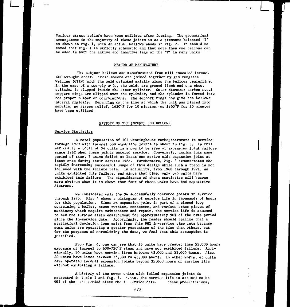
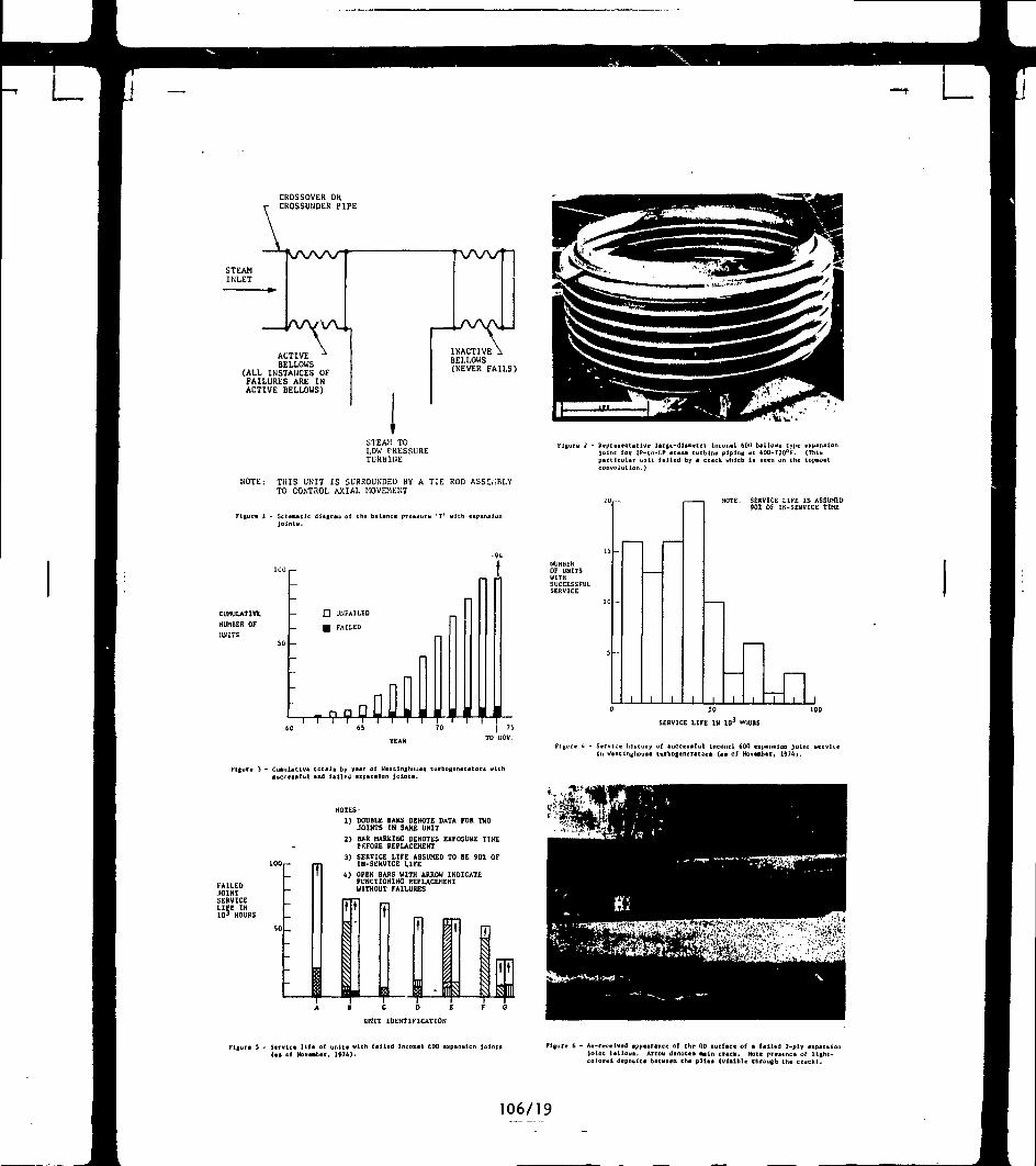
Various stress reliefs have been utilized after forming. The geometricalarrangement in the majority of these joints is as a pressure balanced 'T'as shown in Fig. 1, with an actual bellows shown in Fig. 2. It should benoted that Fig. 1 is strictly schematic and that more than one bellows canbe used in both the active and inactive legs of the 'T' in many units.
METHOD OF MANUFACTURE
The subject bellows are manufactured from mill annealed Inconel600 wrought sheet. These sheets are joined together by gas tungstenwelding (GTAW) with the weld oriented axially along the bellows centerline.In the case of a two-ply u it, the welds are ground flush and one sheetcylinder is slipped inside the other cylinder. Outer diameter carbon steelsupport rings are slipped over the cylinder, and the cylinder is formed intothe proper number of convolutions. The support rings now give the bellowslateral rigidity. Depending on the time at which the unit was placed intoservice, no stress relief, 1650°F for 10 minutes, or 1800°F for 10 minuteshave been utilized.
u
HISTORY OF THE INCONEL 600 BELLOWS
Service Statistics
A total population of 101 Westinghouse turbogenerators in servicethrough 1973 with Inconel 600 expansion joints is shown in Fig. 3. In thisbar chart, a total of 94 units is s'.iown to be free of expansion joint failuresince 1962 when these joints entered service. Conversely, during this sameperiod of Lime, 7 units failed at least one active side expansion joint atleast once during their service life. Furthermore, Fig. 3 demonstrates therapidly increasing successful usage of this design while such a trend is notfollowed with the failure rate. In actuality, from 1968 through 1971, nounits exhibited this failure, and since that time, only two units haveexhibited this failure. The significance of these statistics will becomemore obvious when it is shown that four of these units have had repetitivedistress.
We considered only the 94 successfully operated joints in servicethrough 1973. Fig. 4 shows a histogram of service life in thousands of hoursfor this population. Since an expansion joint is part of a closed loopcontaining a boiler, steam turbine, condenser, and various other pieces ofmachinery which require maintenance and repair, the service life is assumedto See the turbine steam environment for approximately 90% of the time periodsince the in-service date. Accordingly, the reader should realize that astatistical deviation does exist from this 90% in-service time data becausesome units are operating a greater percentage of the time than others, butfor the purposes of normalizing the data, we feel that this assumption isjustified.
From Fig. 4, one can see that 13 units have greater than 55,000 hoursexposure of Inconel to 600-720°F steam and have not exhibited failure. Addi-tionally, 10 units have service lives between 45,000 and 55,000 hours. Also,20 units have lives between "35,000 to 45,000 hours. In other words, 43 unitshave operated Inconel expansion joints beyond 35,000 hours of service lifewithout exhibiting a failure.
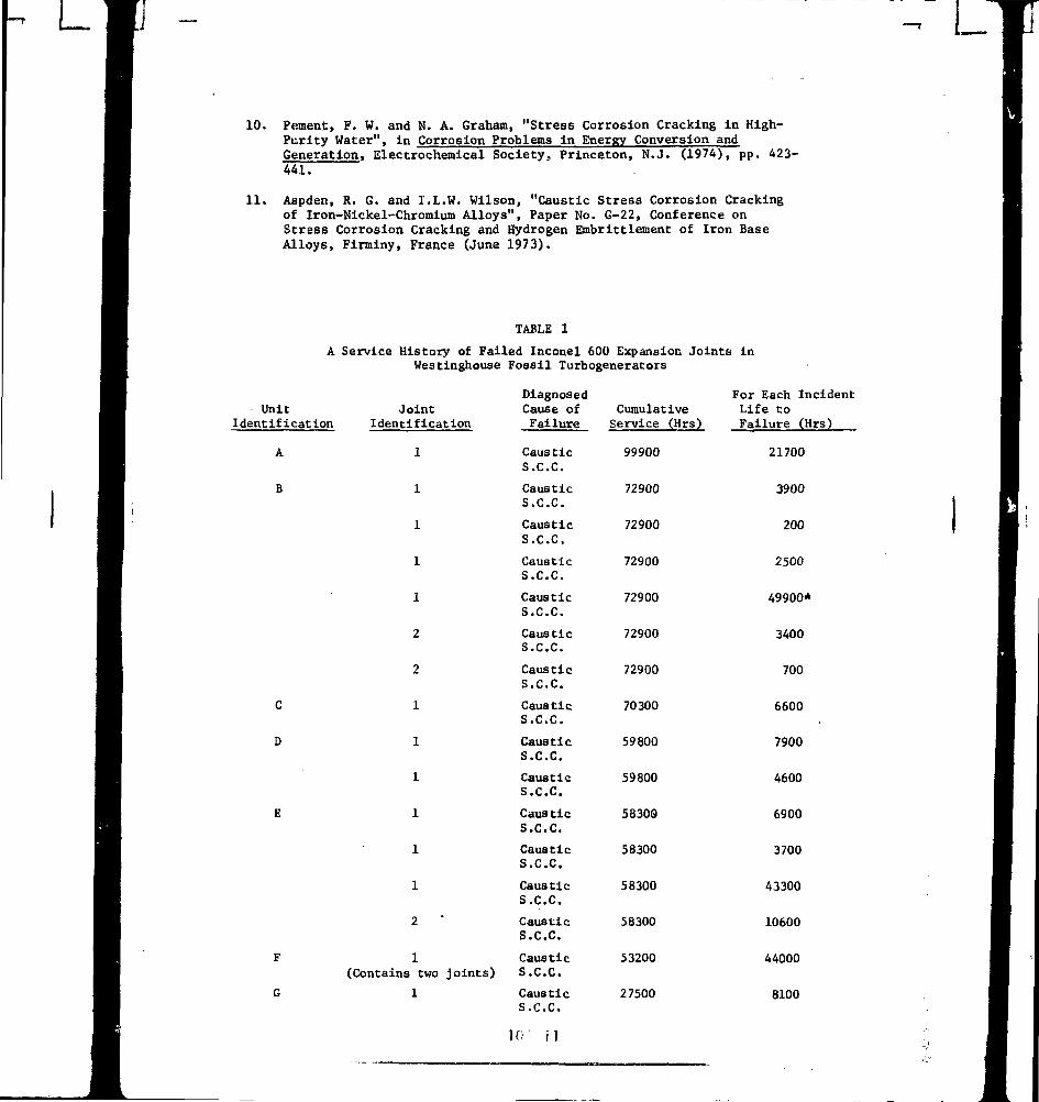
A history of the seven units with failed expansion joints ispresented in 'idl.le 1 and Fig. 5. /vain, the servi. L life is assume! to be90% of the ι i-.i- ι . riod since the I, : rvice date. these presentations,
Ó/2
L
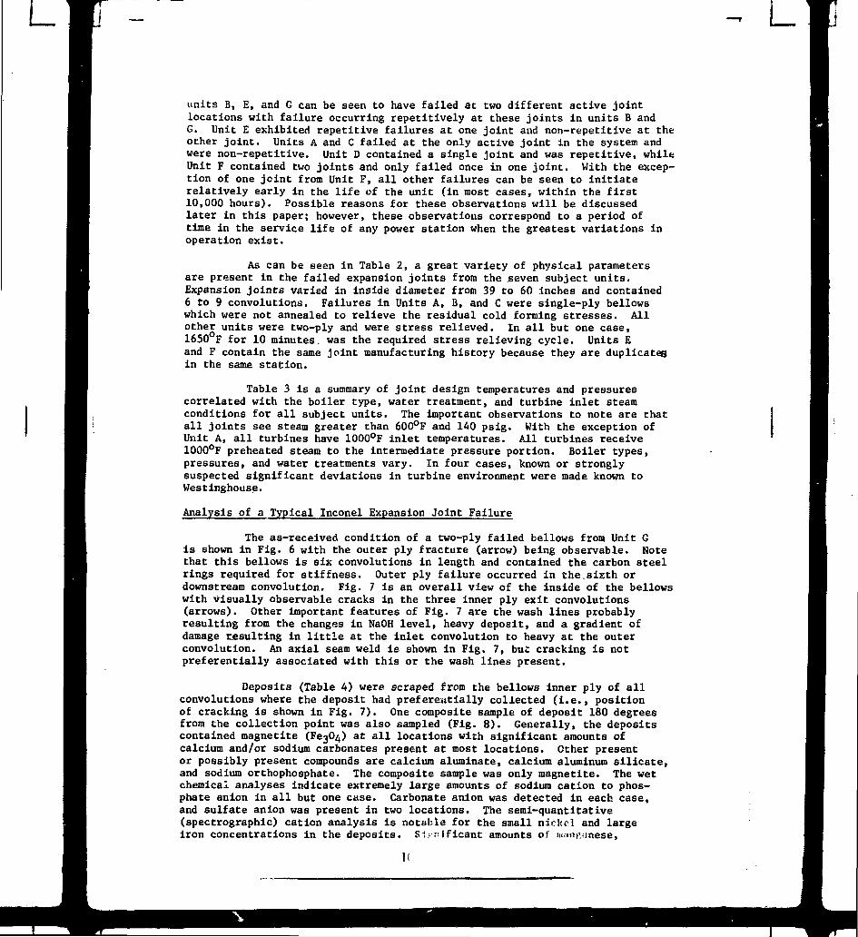
units Β, Ε, and G can be seen to have failed at two different active jointlocations with failure occurring repetitively at these joints in units Β andG. Unit Ε exhibited repetitive failures at one joint and non-repetitive at theother joint. Units A and C failed at the only active joint in the system andwere non-repetitive. Unit D contained a single joint and was repetitive, whileUnit F contained two joints and only failed once in one joint. With the excep-tion of one joint from Unit F, all other failures can be seen to initiaterelatively early in the life of the unit (in most cases, within the first10,000 hours). Possible reasons for these observations will be discussedlater in this paper; however, these observations correspond to a period oftime in the service life of any power station when the greatest variations inoperation exist.
As can be seen in Table 2, a great variety of physical parametersare present in the failed expansion joints from the seven subject units.Expansion joints varied in inside diameter from 39 to 60 inches and contained6 to 9 convolutions. Failures in Units A, B, and C were single-ply bellowswhich were not annealed to relieve the residual cold forming stresses. Allother units were two-ply and were stress relieved. In all but one case,1650°F for 10 minutes, was the required stress relieving cycle. Units Eand F contain the same joint manufacturing history because they are duplicatesin the same station.
Table 3 is a summary of joint design temperatures and pressurescorrelated with the boiler type, water treatment, and turbine inlet steamconditions for all subject units. The important observations to note are thatall joints see steam greater than 600°F and 140 psig. With the exception ofUnit A, all turbines have 1000°F inlet temperatures. All turbines receive1000°F preheated steam to the intermediate pressure portion. Boiler types,pressures, and water treatments vary. In four cases, known or stronglysuspected significant deviations in turbine environment were made known toWestinghouse.
Analysis of a Typical Inconel Expansion Joint Failure
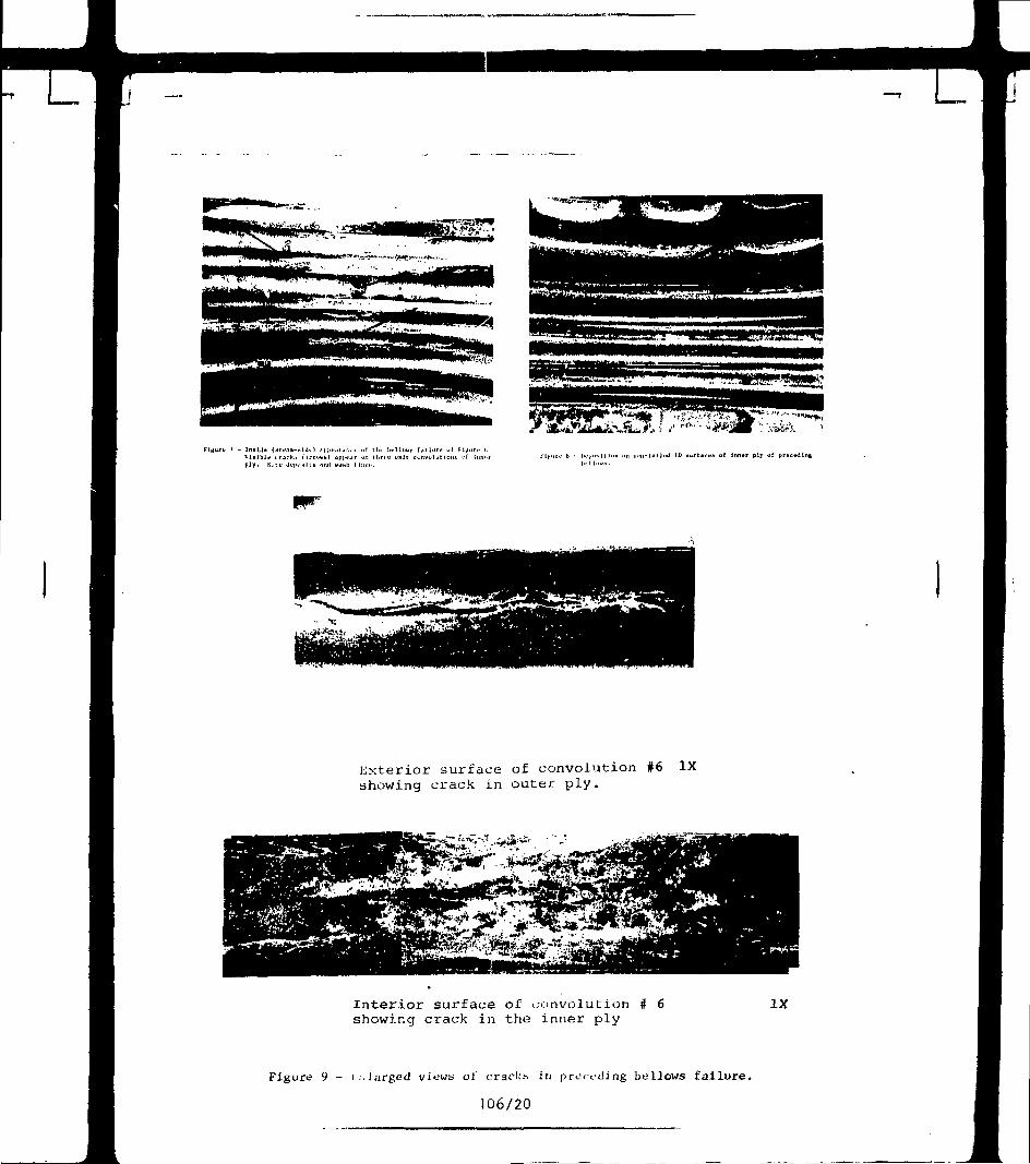
The as-received condition of a two-ply failed bellows from Unit Gis shown in Fig. 6 with the outer ply fracture (arrow) being observable. Motethat this bellows is six convolutions in length and contained the carbon steelrings required for stiffness. Outer ply failure occurred in the.sixth ordownstream convolution. Fig. 7 is an overall view of the inside of the bellowswith visually observable cracks in the three inner ply exit convolutions(arrows). Other important features of Fig. 7 are the wash lines probablyresulting from the changes in NaOH level, heavy deposit, and a gradient ofdamage resulting in little at the inlet convolution to heavy at the outerconvolution. An axial seam weld is shown in Fig. 7, bui: cracking is notpreferentially associated with this or the wash lines present.
Deposits (Table A) were scraped from the bellows inner ply of allconvolutions where the deposit had preferentially collected (i.e., positionof cracking is shown in Fig. 7). One composite sample of deposit 180 degreesfrom the collection point was also sampled (Fig. 8). Generally, the depositscontained magnetite (Έβ^Ο^) at all locations with significant amounts ofcalcium and/or sodium carbonates present at most locations. Other presentor possibly present compounds are calcium aluminate, calcium aluminum silicate,and sodium orthophosphate. The composite sample was only magnetite. The wetchemical analyses indicate extremely large amounts of sodium cation to phos-phate anion in all but one case. Carbonate anion was detected in each case,and sulfate anion was present in two locations. The semi-quantitative(spectrographic) cation analysis is notable for the small nickel and largeiron concentrations in the deposits. Significant amounts of HKin
1C
silicon, titanium, aluminum, and calcium were noted,only in the composite sample.
Copper was significant
The significance of these observations associated with the deposittype and location is two-fold. First, the fact that the heavy deposit build-up is located only over a small circumferential arc and is the same arc fromconvolution to convolution indicates that the corrodant dropped out of thesteam as a liquid to find the geometrically lowest point of the bellows. Thewash lines are an indication that the machine vibration and/or steam aero-dynamics kept the corrodant puddles in motion. Due to the construction of thejoint, the upstream convolutions are sealed from the steam path; hence, thedownstream convolutions receive the bulk of the corrodant and lesser amountsof corrodant are progressively deposited in the upstream convolutions.Fig. 8 is a view of,the non-corrcdant bearing deposition on the convolutions.Note that it does not preferentially colJsct and is innocuous.
The second reason for deposit analysis is isolation and/or estimationof the corrodant. For example, a major presence of carbonate anion and sodiumcation can indicate significant NaOH which has converted to sodium carbonateby combining with atmospheric carbon dioxide. Conversely, aluminum cationgenerally represents the abrasive media (alumina) used to clean the turbineinternals. Phosphate may be a residual chemical from the water treatment,and sulfate may be from H2SO4 ion exchange regeneration or from incompletedemineralization.
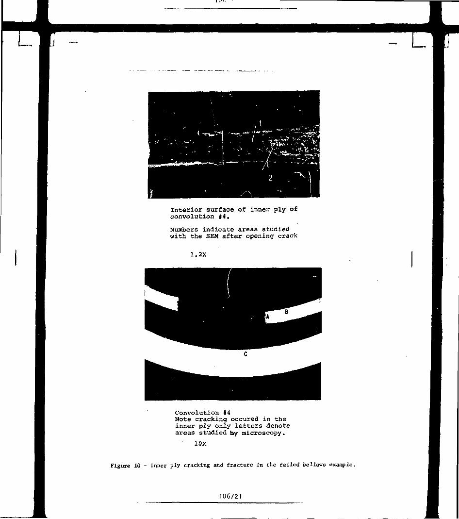
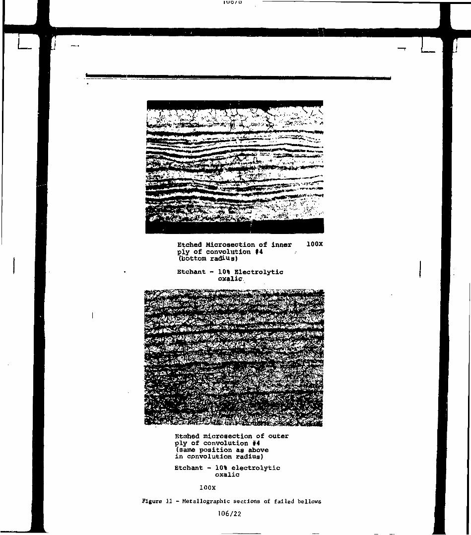
A closer view of the outer ply exterior as well as the inner plyinterior surface of convolution 6 is shown in Fig. 9 after scraping a depositsample. Both cracks are visually non-linear, but the inner ply cracking isdefinitely branched. No gross pitting is observed. Visual observation of theinner ply surface at convolution 4 shows a finer, non-linear crack with aslight visually observable amount of branching. A micro-section through thiscrack does not reveal cracking in the outer ply but the inner ply was completelyseparated (Fig. 10). More detailed metallography of the etched inner and outerplys of convolution 4 is presented in Fig. 11. The plane of section isparallel to the rolling direction of the sheet prior to bellows fabricationand shows micro-segregation (banding) associated with both plys. Fig. 12 isa higher magnification micrograph showing severe carbide agglomeration in thebands as well as carbide agglomeration in annealing twins, the grain boundaries,and the grain matrix. The bulk chemistries indicate the bellows meet Inconel600 requirements and do not indicate compositional variations with a singlesheet; see Table 5. In other failures, banding may or may not be typical,and the failure mode does not appear to be related to this microstructure.An SEM view of the intergranular fracture is shown in Fig. 13.
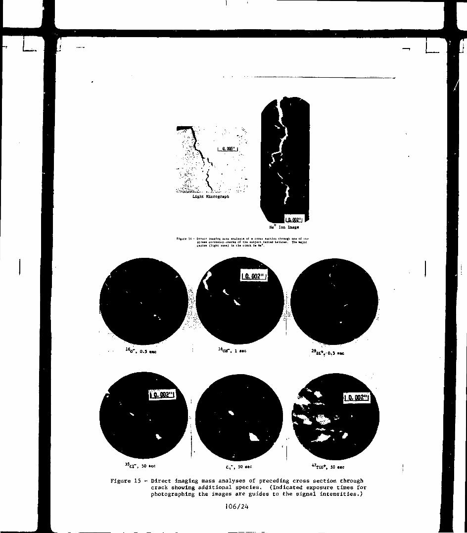
To prove conclusively the presence of the hydroxide and sodium ionsin the branched, intergranular cracks, an unetched micro-specimen was inspectedusing the direct imaging mass analyzer. By this technique, one is able tosort ions by charge and atomic weight on a micro-scale with the resultingexposures being'shown in Figs. 14 and 15. Extremely large amounts of sodiumcation, hydroxide anion, and silicon cation are present. Lesser amounts(longer exposures) of Cl~, C2~, and TiO
+ ions are present. The carbon ispresent as grain boundary carbides while the TiO is a heterogeneouslydispersed element in Inconel. In short, no doubt remains that the failuremechanism is steam born caustic stress corrosion cracking; however, thecorrodant chemistry and its relationship to service experience will bediscussed in the next section.
FAILURE MECHANISMS BASED ON STRESS CORROSION OBSERVATIONSIN INCONEL, INCLUDING NEW OBSERVATIONS
A number of new tests on the stress corrosion behavior of Inconel600 were performed as part of this investigation. These are reported in detail,together with pertinent aspects of previously published literature.
Stress Corrosion Cracking of Inconel 600 in High-Purity Water
This is an extensively investigated subject to which reference tothe original literature is required for details.i1""^) M o s t testing has beendone at 630-662°F, temperatures which include the bellows application. Theselaboratory tests must therefore be included in evaluating both the successfulperformance of most, of the bellows expansion joints and the few failures whichhave been observed. Tests have nearly always been confined to highly stressedInconel, which is pertinent to the bellows application, using mill-annealedor solution-treated material, frequently pickled. Apart from the initialtests involving essentially complete fracture or plastically deformed samplesin 3 or 4 month exposures at 662°F,O the results of over a decade of testinghave been characterized by a lack of statistical reproducibility of the numberof attacked specimens and increasingly long exposure times to produce veryshallow intergranular cracks which are often detectable only through exten-sive metallographic examination. Controversies over test methodology,including sample surface conditions and test water purities, have confusedthe interpretation of the results.
We have recently examined this phenomenon in some detail and haveobservations which are typical in this area.^1^ Highly stressed, U-bendsamples in a variety of metallurgical conditions in both polished and pickledsurface conditions, were observed after 16,000 hours exposure to continuouslydeionized, high-purity water of low dissolved oxygen concentrations ( 10 ppb)at 630°F. Mill-annealed, unpickled or pickled Inconel U-bends show no cracking.Laboratory heat treatments representative of industrial practice, such asannealing at 1800°F or 1650°F showed no attack, if not pickled, and only oneof 8 pickled samples in this group (one 1800°F annealed sample) showed slightattack (isolated grain boundary penetration). Solution annealed (2010°F),large grained Inconel U-bends resisted attack if non-pickled, except for asingle grain boundary penetration one grain deep on one out of 11 samples.Pickled, solution annealed material showed an increased tendency for shallowintergranular cracking, seemingly in agreement with literature observations.
These results confirm the literature trend for long "incubation"periods (>10,000 hours) to produce shallow, sporadic, intergranular cracks.They also showed, however, that Inconel treated to industrially importantmicrostructures (as these joints contain), even when severely plasticallydeformed and highly stressed, resists attack under an extended exposure tohigh purity water. The duration of this extended exposure was considerablylonger than thé life of many of the failed bellows described above.
Stability of Inconel Toward Corrosion at the Application Temperatures
Samples of mill-annealed Inconel, 0.03% C, were examined by scan-ning electron microscopy for carbide amounts and distribution before andafter the 16,000 hour exposure at 63O°F.- Fig. 16, from Reference (10), showsthe results. No significant differences were observed. Boiling corrosiontests in ASTM-A262, ferric-sulfate-inhibited, sulfuric acid showed that themill-anncolt Λ, 16,000-hour-exposed materi.-Ί corroded at a l.-i-r rate (25%less) thai ι·;· posed material of the sar lioat. (By conti : , mill annealed
material of this same heat when also treatea for 10 hours at 1200°F, to a"sensitized" structure, completely dissolved in this same test.) The ASTM-A262 results pertain strictly to the single heat of this tes\"., and a 25%reduction in corrosion rate is not necessarily significant. However, boththe SEM's and the ASTM-A262 results clearly do not give any indications ofchanges in the long-term stability of Inconel due to prolonged exposure at630°F.
Stress Corrosion Experiments in Fused Caustics and Low TemperatureAqueous Caustics
Deposits found at 07: near failures contained varying amounts ofsodium carbonate, bicarbonate, sulfate, phosphate, and in some cases, smallamounts of sodium hydroxide (caustic). The large amounts of alkaline carbon-ates probably originated from sodium hydroxide which, when exposed to air,united with carbon dioxide and moisture, and subsequently converted into thecarbonate and bicarbonate. Chloride concentrations in most deposits weregenerally below 0.10%.
Because of the presence of caustic compounds in these analyses, apreliminary qualitative "crack-no crack" program was undertaken to establishparameters that might lead to caustic stress corrosion cracking of Znconel600. These tests were carried out using "U" bend and Erichsen cup specimensin an air atmosphere at 700°F with fused caustic, and caustic containingadditions of sulfate, chromate, chloride, or carbonate. No cracking occurredafter a two week test period. The results obtained from these tests aresummarized in Table 6. Subsequently, tests with specimens under an appliedaxial load and in intimate contact with known aqueous corrodants at 212°Fwere made. The solutions were composed of 2U% Na2SO4~20X Na2CO3-O.l% PbCrO^with and without 2% Na3PO^ additions. No cracking was noted in the 170 to650 hour test periods. These test results are tabulated in Table 7.
Caustic Stress Corrosion Behavior in Steam
The above tests, while severe, lacked the environment of pressurized,supeiheated steam as occurs in a bellows. A test system was devised whereina novel, corrodant-containing, "cupped" tensile specimen could be exposed toa non-oxidizing, superheated steam atmosphere under an applied axial stress.Photographs of an unassembled and assembled specimen are exhibited in Fig. 17.The cup served as a receptable for the corrodant and surrounded the gaugelength of the tensile specimen for approximately one-half of its length.This allowed steam to circulate around the specimen. Thus, the specimen wassubjected to multiple exposure effects including the effects of bulk deposit,vapor or capillary action arising from the bulk deposit, as well as interfaceeffects. Additionally, one could compare the effects of a corrodent on anon-stressed member (cup) to a stressed area (gauge length) under the sameconditions of test. In securing the cup to the specimen with a nut, the balland socket design was such that no leakage of corrodant occurred and notorsional stresses were imposed upon the gauge length.
A boiler was made from a 3 liter reaction flask and heating mantle.Argon gas, after passing through a porous diffusing stone in the boiler water(high-purity, deionized water), carried the steam to the furnace retort andprovided the necessary non-oxidizing atmosphere. Containment of this atmos-phere was by maans of an enclosed Pyrex tube located in the heating zone of asplit furnace. Two electronic controllers provided the necessary instrumenta-tion for maintaining control of the water level and temperature, therebyreducing the need for constant surveillance .nd attendance.
106/6
L
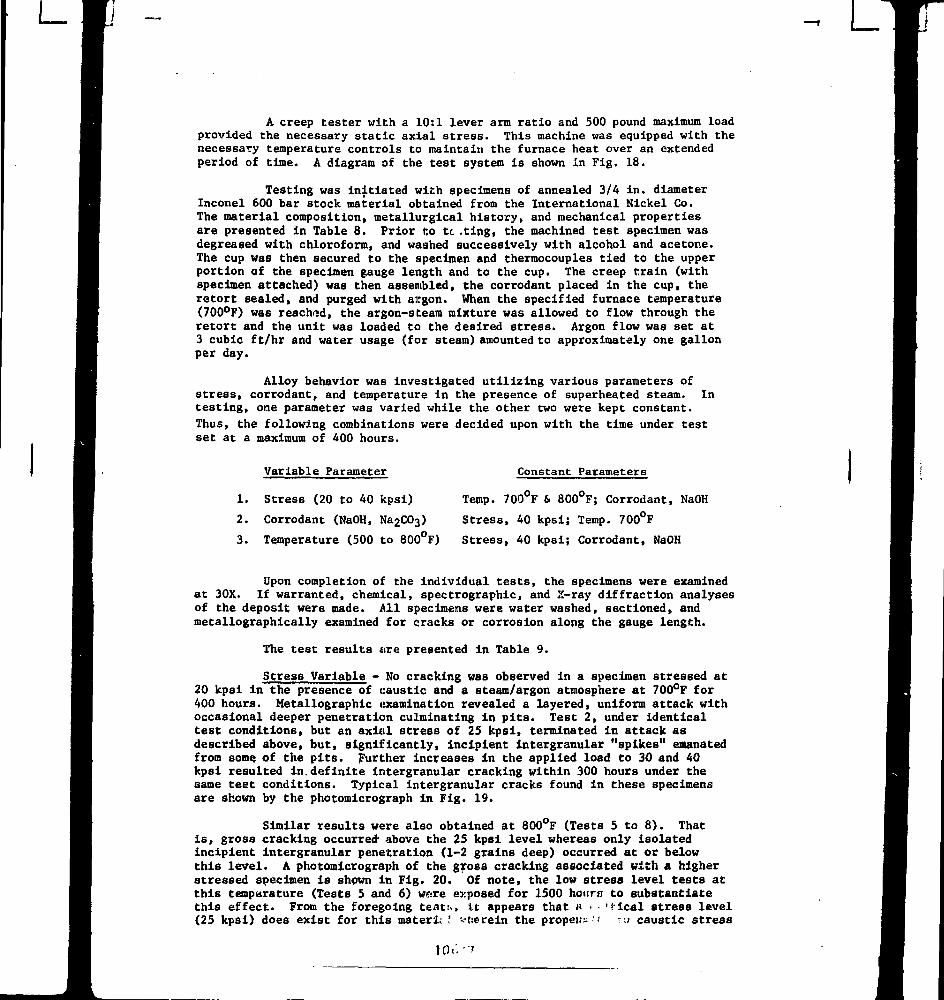
A creep tester with a 10:1 lever arm ratio and 500 pound maximum loadprovided the necessary static axial stress. This machine was equipped with thenecessary temperature controls to maintain the furnace heat over an extendedperiod of time. A diagram of the test system is shown in Fig. 18.
Testing was initiated with specimens of annealed 3/4 in. diameterInconel 600 bar stock material obtained from the International Nickel Co.The material composition, metallurgical history, and mechanical propertiesare presented in Table 8. Prior t:o tc. .ting, the machined test specimen wasdegreaeed with chloroform, and washed successively with alcohol and acetone.The cup was then secured to the specimen and thermocouples tied to the upperportion of the specimen gauge length and to the cup. The creep train (withspecimen attached) was then assembled, the corrodent placed in the cup, theretort sealed, and purged with argon. When the specified furnace temperature(700°F) was reached, the argon-steam mixture was allowed to flow through theretort and the unit was loaded to the desired stress. Argon flow was set at3 cubic ft/hr and water usage (for steam) amounted to approximately one gallonper day.
Alloy behavior was investigated utilizing various parameters ofstress, corrodant, and temperature in the presence of superheated steam. Intesting, one parameter was varied while the other two were kept constant.Thus, the following combinations were decided upon with the time under testset at a maximum of 400 hours.
Variable Parameter
1. Stress (20 to 40 kpsi)
2. Corrodant (NaOH,
3. Temperature (500 to 800°F)
Constant Parameters
Temp. 700°F & 800°F; Corrodant, NaOH
Stress, 40 kpsi; Temp. 700°F
Stress, 40 kpsi; Corrodant, NaOH
Upon completion of the individual tests, the specimens were examinedat 30X. If warranted, chemical, spectrographs, and X-ray diffraction analysesof the deposit were made. All specimens were water washed, sectioned, andmetallographically examined for cracks or corrosion along the gauge length.
The test results are presented in Table 9.
Stress Variable - No cracking was observed in a specimen stressed at20 kpsi in the presence of caustic and a steam/argon atmosphere at 700°F for400 hours. Hetallographic examination revealed a layered, uniform attack withoccasional deeper penetration culminating in pits. Test 2, under identicaltest conditions, but an axial stress of 25 kpsi, terminated in attack asdescribed above, but, significantly, incipient intergranular "spikes" emanatedfrom some of the pits. Further increases In the applied load to 30 and 40kpei resulted in.definite intergranular cracking within 300 hours under thesame teet conditions. Typical intergranular cracks found in these specimensare shown by the photomicrograph in Fig. 19.
Similar results were also obtained at 800°F (Tests 5 to 8). Thatis, gross cracking occurred- above the 25 kpsi level whereas only isolatedincipient intergranular penetration (1-2 grains deep) occurred at or belowthis level. A photomicrograph of the gross cracking associated with a higherstressed specimen is shown in Fig. 20. Of note, the low stress level tests atthis temperature (Tests 5 and 6) were exposed for 1500 hours to substantiatethis effect. From the foregoing teat:., it appears that « • - 'Kcal stress level(25 kpsi) does exist for this materie' '«herein the propel);·' m caustic stress
L
corrosion cracking is minimal at 700 and 800°F.
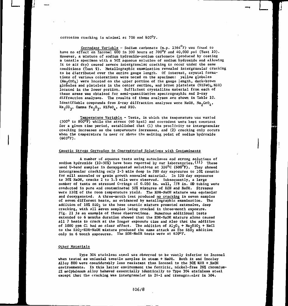
Corrodant Variable - Sodium carbonate (m.p. 1564°F) was found tohave no effect on Inconel 600 in 300 hours at 700°F and 40,000 psi (Test 10).However, a mixture of sodium hydroxide-sodium carbonate (produced by coatinga tensile specimen with a 50% aqueous solution of sodium hydroxide and allowingit to air dry) caused severe intergranular cracking to occur under the sameconditions (Test 9). Metallographic examination revealed intergranular crackingto be distributed over the entire gauge length. Of interest, crystal forma-tions of various colorations were noted on the specimen: yellow globules(Na2CrO^) were located on the upper portion of the gauge length, dark-brownglobules and platelets in the center section, and brown platelets (NiFeO^, NiO)located in the lower portion. Sufficient crystalline material from each ofthese areas was obtained for semi-quantitative spectrographs and X-raydiffraction analyses. The results of these analyses are shown in Table 10.Identifiable compounds from X-ray diffraction analyses were NaOH, Na_CrO,,
Na^CO,, Gamma Fe,O,, NiFeO4, and NiO.
Temperature Variable - Tests, in which the temperature was varied(500° to 800°F) while the stress (40 kpsi) and corrodant were kept constantfor a given time period, established that (1) the proclivity to intergranularcracking increases as the temperature increases, and (2) cracking only occurswhen the temperature is near or above the melting point of sodium hydroxide(603°F).
Caustic Stress Corrosion in Concentrated Solutions with Contaminants
A number of aqueous tests using autoclaves and strong solutions ofsodium hydroxide (10-50%) have been reported by our laboratories.Ο Π Theseused U-bend samples in deoxygenated solutions at 316°C (600°F). They showedintergranular cracking only 2-3 mils deep in 200 day exposures to 10% causticfor mill annealed or grain growth annealed material. In 120 day exposuresto 502 NaOH, cracks 2 to 5.5 mils were observed. Subsequently, a largenumber of tests on stressed C-rings of 0.050 in. wall, 7/8 in. OD tubing wereconducted in pure and contaminated 50% mixtures of KOH and NaOH. Stresseswere 110% of the room temperature yield. The KOH-NaOH mixture was equimolarand deoxygenated. A three-month test produced no cracking in seven samplesof seven different heats, as evidenced by metallographic examination. Theaddition of 10% SiO
2 to the base caustic mixture promoted extensive, deep
cracking, with all seven samples being cracked in three-month exposure.Fig. 21 is an example of these observations» Numerous additional cestsextended to 6 months duration showed that the KOH-NaOH mixture alone causedall 7 heats to crack at the longer exposure time and also that the additionof 1000 ppm CI had no clear effect. The addition of AI2O3 + Na2SiO3 + NaClto the SiO2"KOH-NaOH mixture produced the same attack as the S102 additiononly in 6 month exposures. The KOH-NaOH tests were at 620°F.
Other Materials
Type 304 stainless steel was observed to be vastly inferior to Inconelwhen tested as uniaxial tensile samples in steam + NaOH. Both it and IncoloyAlloy 800 were considerably less resistant than Inconel to the 50% KOH +.NaOHenvironments. In this latter environment the ferritic, nickel-free 26% chromium-1% molybdenum alloy behaved essentially identically to Type 304 stainless steelexcept that the cracking was intergranular in 26-1 and transgranular in 304.
106/8
- L LTi
SUMMARY
(1) Service experience of up to 100,000 hours has been obtained withInconel 600 expansion joints in Westinghouse fossil turbogenerators. Sevenunits have exhibited generally repetitive failures out of the total populationof 101. The few failures have been due to an intergranular stress-corrosioncracking process. This experience demonstrates both that Inconel is highlyreliable for this service but that the alloy is not indestructible undercertain conditions for stress corrosion cracking.
(2) The majority of the failures occurred within the first 10,000hours of operation, some within 1000 hours, but some long-term incidentsoccurred. Three long-term incidents involved failures between 40,000 and50,000 hours (Units B, E, and F). Two of these were in Units E and F, whichare in the same station and use a water treatment common to both. The failureinvestigations established that known, caustic-producing excursions occurredsporadically in the common water treatment for these two units. Theseexcursions reasonably explained the several short-term failures in Unit E;hence short duration excursions of the same type are reasonable explanationsof the two failures, one in each unit, which had 40,000 hours or more servicebefore the excursions. The third long-term failure, in Unit B, occurred ona bellows which was field repaired after a short-time failure.
(3) Analyses of failed bellows revealed caustic compounds whichwere present in the bellows environment of superheated steam at 600-720°F.
(A) Laboratory stress-corrosion tests on Inconel 600 in 630°F highpurity water show the alloy in the metallurgical condition of the bellows tobe completely resistant to any stress-corrosion attack over exposure timeshich are too long to apply to the majority of the service failures. On the1\.50°ΐ annealed structure, even pickling in HNO3-HF did not lead to inter-granular attack in laboratory pure water at 630°F, although pickling of othermetallurgical structures, especially the large-grained solution annealedcondition, led to sporadic attack.
(5) Laboratory autoclave testing of Inconel at 600°F in aqueous10% NaOH will not produce failure in the same time as is consistent withservice experience. Much higher caustic concentrations (502) were requiredin aqueous solution to produce extensive cracking, but the presence of SIC^in such caustic causes reduced failure time which is consistent with serviceexperience.
(6) Laboratory axial 700-800°F stress corrosion tests in moltenNaOH and steam showf.d much shorter times to failure than the two previoustests and is probably a much bettor simulation of the service environment.
CONCLUSIONS
Inconel 600 is a highly satisfactory bellows material for turbinepiping expansion joints in uncontaminated superheated steftm service at 600-720°F. Service life of nearly 100,000 hours has been obtained with no tendencyfor stress corrosion cracking by long-term exposure (long incubation periods)to uncontaminated steam. Failures which have occurred are rare, relativelyearly in life, and explicable entirely In terms of caustic stress corrosioncracking. The caustic originates from reasonable and cften establishedexcursions in the boiler water chemistry; these excursions are relativelyrare. Laboratory tests confirm the t·.. ceptibility of Incm,· 1 to causticstress cori'i-lon in either highly c< trated aqueous sol···.-, ims with typical
L
contaminants or in superheated steam. These tests show that Inconel issuperior to Type 304 stainless steel in these environments.
ACKNOWLEDGMENTS
A. R. Pebler and G. G. Sweeney contributed the DIMA results. Wethank J. Kelley, F. X. Baldino, and E. P. Morgan for contributions to thecorrosion work and acknowledge the participation of D. D. Whyte and N. A.Graham. Comments, suggestions, and encouragement were given by R. E. Clark,B. B. Seth, R. G. Aspden, and W. T. Lindsay, Jr.
REFERENCES
1. Coriou, H., R. Grail, M. LeGall, and S. Vettier, "Corrosion Fissurantesous Contrainte de 1'Inconel dans l'Eau a Haute Temperature",3iLColloque de Métallurgie Corrosion (Sèche et Aquese), Centred'Études Nucléaires de Saclay, June 29-30 and July 1, 1959 (NorthHolland Publishing Co., Amsterdam, 1960), pp. 161-169.
2. Copson, H. R. and S. W. Dean, "Effect of Contaminants on Resistanceto Stress Corrosion Cracking of Ni-Cr Alloy 600 in Pressurized Water",Corrosion i» 3-10 (1965).
3. Coriou, H., L. Grail, C. Mahieu, and M. Pelas, "Sensitivity to StressCorrosion and Intergranular Attack of High-Nickel Austenitic Alloys",Corrosion J22, 280-290 (1966).
4. Coriou, H., L. Grail, P. Olivier, and H. Willermoz, "Influence ofCarbon and Nickel Content on Stress Corrosion Cracking of AusteniticStainless Alloys, in Pure or Chlorinated Water at 35O°C", InternationalConference on Fundamental Aspects of Stress Corrosion Cracking, TheOhio State University, Columbus, Ohio, Sept. 11-15, 1967.
5. Rentier, R. M. and I. H. Welinsky, "Effect of HNO3-HF Pickling onStress Corrosion Cracking of Ni-Cr-Fe Alloy 600 in High Purity Waterat 660°F", U. S. Atomic Energy Comm. Rept. WAPD-TM-944, October 1970.
6. Foster, G. G. and J. W. Taylor, "Stress Assisted Corrosion of Inconel600 Heat Exchanger Tubing in High Temperature Water", British NuclearEnergy Society Conference on Corrosion, Paper No. 8, p. 87-102,London, July 1971.
7. HUbner, W., B. Johansson, and M. de Pourbaix, "Studies of the Tendencyof Intergranular Corrosion Cracking of Austenitic Fe-Cr-Ni Alloys inHigh Purity Water at 300°C", Report AE-437, Aktiebolaget Atomenergi,Studsvik, Nyköping, Sweden, October 1971.
8. Flint, G. N. and B. A. Weldon, "Some Investigations into the StressCorrosion Behaviour of Fe-Ni-Cr Alloys in High Temperature Water",Paper P-PR-56, Congres "Chimie de l'eau et corrosion aqueuse dansles générateurs de vapeur", Ermenonville, March 13-17, 1972.
9. Blanchet, J., Η. Coriou, L. Grail, C. Mahieu, C. Otter, and G. Turluer,"Influence de Divers Paramètres sur la Fissuration Intergranulairedes Alliages Inconel 600 et X75O dans l'Eau Pure a Haute Temperature",Conference on Stress Corrosion Cracking and Hydrogen Embrittlement ofIron Base Alloys, Paper C-13, Fintiny, June 1973.
L
10. Pement, F. W. and Ν. A. Graham, "Stress Corrosion Cracking in High-
Purity Water", in Corrosion Problems in Energy Conversion and
Generation, Electrochemical Society, Princeton, N.J. (1974), pp. 423-
441.
11. Aspden, R. G. and Ï.L.W. Wilson, "Caustic Stress Corrosion Crackingof Iron-Nickel-Chromium Alloys", Paper No. G-22, Conference onStress Corrosion Cracking and Hydrogen Embrittlement of Iron BaseAlloys, Firminy, France (June 1973).
TABLE 1
A Service History of Failed Inconel 60Ü Expansion Joints inWestinghouse Fossil Turbogenerators
UnitIdentification
A
Β
C
D
Ε
F
G
Joint
Identification
1
1
1
1
1
2
2
1
1
1
1
1
1
2
1
(Contains two joints)
1
Diagnosed
Cause of
Failure
Caustic
S.C.C.
CausticS.C.C.
Caustic
S.C.C.
CausticS.C.C.
Caustic
S.C.C.
CausticS.C.C.
CausticS.C.C.
CausticS.C.C.
CausticS.C.C.
CausticS.C.C.
CausticS.C.C.
Caustic
S.C.C.
CausticS.C.C.
CausticS.C.C.
CausticS.C.C.
CausticS.C.C.
10 il
CumulativeService (Hrs)
99900
72900
72900
72900
72900
72900
72900
70300
59800
59800
5830Θ
58300
58300
58300
53200
27500
For Each Incident
Life to
Failure (Hrs)
21700
3900
200
2500
49900*
3400
700
6600
7900
4600
6900
3700
43300
10600
44000
8100
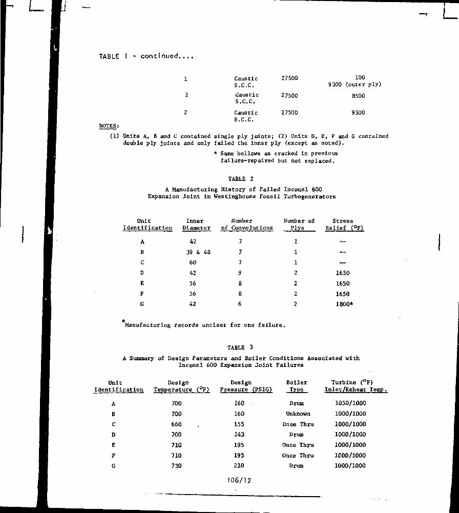
TABLE 1 - continued
1
2
2
NOTES:
CausticS.C.C.
CausticS.C.C.
CausticS.C.C.
27500
27500
27500
100
9300 (outer ply)
8500
9300
(1) Units Α, Β and C contained single ply j o i n t s ; (2) Units D, E, F and G containeddouble ply j o i n t s and only failed the inner ply (except as noted).
* Same bellows as cracked in previousfailure-repaired but not replaced.
TABLE 2
A Manufacturing History of Failed Inconel 600
Expansion Joint in Westinghouse Fossil Turbogenerators
Unit
Identification
A
Β
C
D
Ε
F
G
InnerDiameter
42
39 & 48
60
42
56
56
42
Numberof Convolutions
7
7
7
9
8
8
6
Number of
Plys
1
1
1
2
2
2
2
Stress
Relief (°F)
—
—
—
1650
1650
1650
1800*
Manufacturing records unclear for one failure.
TABLE 3
A Summary of Design Parameters and Boiler Conditions Associated with
Inconel 600 Expansion Joint Failures
UnitIdentification
A
Β
C
D
Ε
F
G
Design
Temperature (°F)
700
700
660
700
710
710
730
DesignPressure (PSIG)
160
160
155
143
195
195
210
106/12
Boiler
Type
Drum
Unknown
Once Thru
Drum
Once Thru
Once Thru
Drum
Turbine (°F)
Inlet/Reheat Temp.
1050/1000
1000/1000
1000/1000
1000/1000
1000/1000
1000/1000
1000/1000
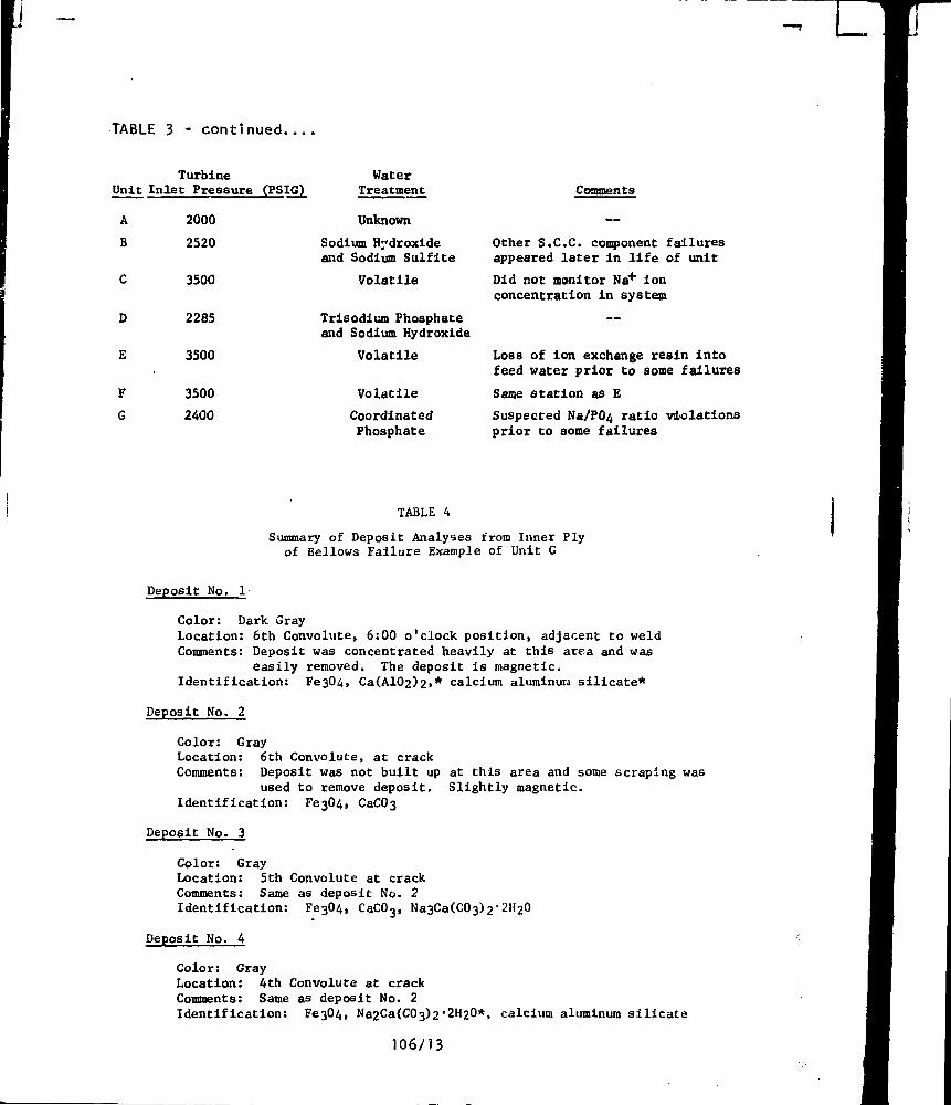
TABLE 3 - continued
-< L.
Unit
A
Β
C
D
Ε
F
G
TurbineInlet Pressure (PSIG)
2000
2520
3500
2285
3500
3500
2400
WaterTreatment
Unknown
Sodium Hydroxideand Sodium Sulfite
Volatile
Trisodium Phosphateand Sodium Hydroxide
Volatile
Volatile
CoordinatedPhosphate
Comments
Other S.C.C. component failuresappeared later in life of unit
Did not monitor Na+ ion
concentration in system
Loss of ion exchange reain intofeed water prior to some failures
Same station as E
Suspected Na/ΡΟή ratio violations
prior to some failures
TABLE 4
Summary of Deposit Analyses from Inner Plyof Bellows Failure Example of Unit G
Deposit No. 1
Color: Dark GrayLocation: 6th Convolute, 6:00 o'clock position, adjacent to weld
Comments: Deposit was concentrated heavily at this area and waseasily removed. The deposit is magnetic.
Identification: Fe304, Ca(A102>2»* calcium aluminun silicate*
Deposit No. 2
Color: GrayLocation: 6th Convolute, at crackComments: Deposit was not built up at this area and some scraping was
used to remove deposit. Slightly magnetic.Identification: Fe304, CaC03
Deposit No. 3
Color: GrayLocation: 5th Convolute at crackComments: Same as deposit No. 2Identification:
Deposit No. 4
CaC03
Color: GrayLocation: 4th Convolute at crackComments: Same as deposit No. 2Identification: Fe304, Na2Ca(C03)2'2H20*, calcium aluminum silicate
106/13
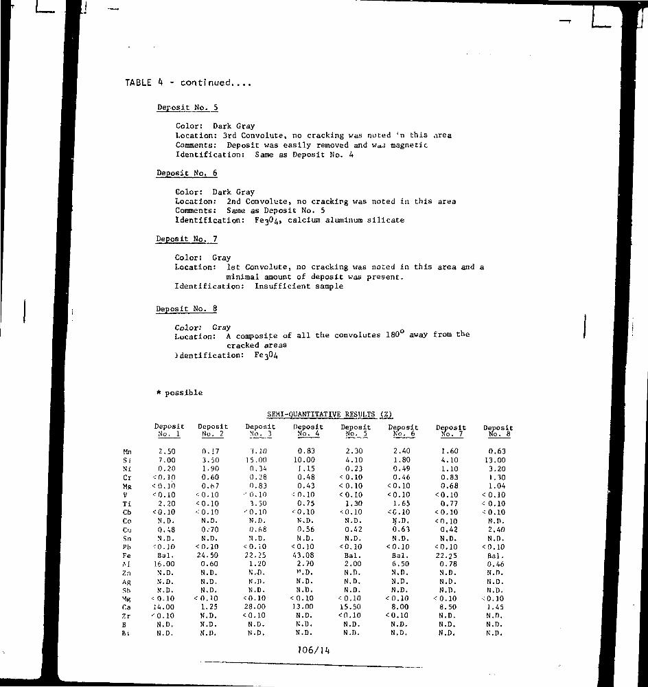
TABLE - continued....
Deposit No. 5
Color: Dark Gray
Location: 3rd Convolute, no cracking was noted !n this area
Comments: Deposit was easily removed and waj magnetic
Identification: Same as Deposit Mo. A
Deposit No. 6
Color: Dark Gray
Location: 2nd Convolute, no cracking was noted in this area
Comments: Same as Deposit No. 5
Identification: VejQii» calcium aluminum silicate
Deposit No. 7
Color: Gray
Location: 1st Convolute, no cracking was noted in this area and a
minimal amount of deposit was present.
Identification: Insufficient sample
Deposit No. 8
Color: Gray
Location: A composite of all the convolutes 180 away from the
cracked areas
Identification: Fe304
possible
SEMI-QUANTITATIVE RESULTS (%)
ΜηSiNiCΓ
MfcVT iCbCo
CuSnPbFeΛ1In
AgSb1gCaZrΒBi
DepositNo. 1
270
<0< 0
<o2
<0Ν
0Ν
<0
.50
.00
.20
.10
.10
.10
.20
.10
. D .
.48
. D .
.10Bal.
16Ν
ΝΝ
< 014
- 0ΝΝ
.00
. η .. D .. D ..10.00.10. D .. D .
DepositNo. 2
03100
< 0<0< 0
Ν
0Ν
< 024
0ΝΝΝ
<01ΝΝΝ
.17
.50
.90
.60
.67
.10
.10
.10
.D.
.•70
.D.
.10
.50
.60
. D .
. D .
. D .
.10
.25
. D .
. D .
.D.
DepositNo. 3
3.1015.000.340.280.83
·- 0.103.50
·- ο. ίοN.D.0.68N.D.
< 0 . ί 022.25
1.20Ν.Z>.N.D.N.D.
<0.1028.00
<0.10N.D.N.D.
DepositNo. 4
0.8310.00
1.150.480.43
-' 0.100.75
<0.10N.D.0.56N.D.
<0.1043.08
2.70>>T.D.
N . D .
N . D .
< 0.1013.00
N.D.N.D.N.D.
106/14
DepositNo. 5
2.304.100.23
<0.10< 0.10<0.10
1.30<0.10
N.D.0.42N.D.
<0.10Bal.2.00N.D.N.D.N.D.
< 0.1015.50
<0.10N.D.N.D.
DepositNo. 6
2100
< 0< 0
1
<cΝ0
Ν< 0,
.40
.80
.49
.46
.10
.10
. 6 5
.10
. 0 .
.63
.D.
.10Bal.6.Ν.Ν.Ν.
< 0.8.
< 0.Ν.Ν.
.50,D.D.
,D.100010D.D.
DepositNo, 7
1
4100
< 00
< 0< 0
0Ν
< 022,
0,N.N,N.
< 0.8.N.N.N.
.60
.10
.10
. 8 3
.68
.10
.77
.10
.10
.42
. D .
.10
.25
.78
.D.
.D.D,
,1050D.D.D.
DepositNo. 8
0.6313.003.201.301.04
<0.10< 0.10<0.10
N.D.2.40N.D.
<0.10Bal.0.46N.D.N.D.N.D.
•0.101.45N.D.N.D.N.D.
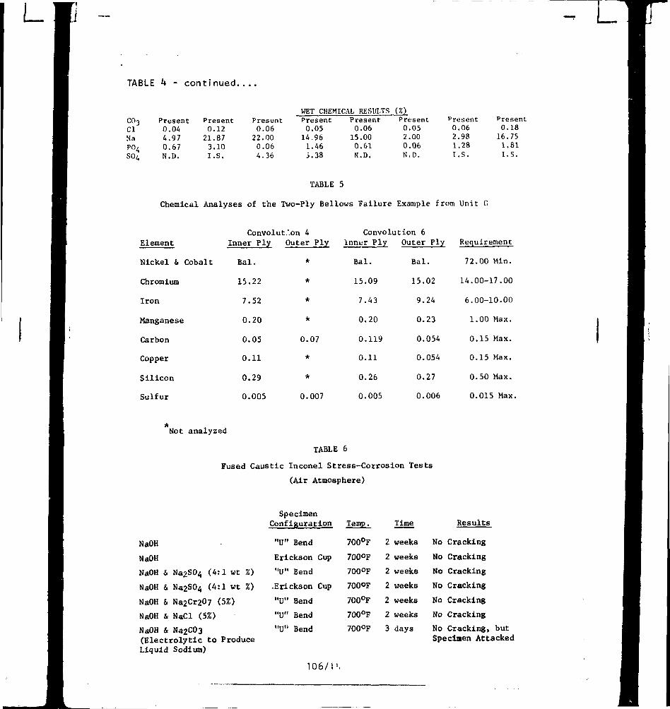
TABLE k - continued
WET CHEMICAL RESULTS (%)co3ClNaPO/SOA
Present0.044.970.67N.D.
Present0.1221.873.10I.S.
Present0.06
22.000.064.36
Present0.0514.961.46i.38
Present0.0615.000.61N.D.
Present0.052.000.06N.D.
Present0.062.981.28I.S.
Present0.1816.751.81I.S.
TABLE 5
Chemical Analyses of the Two-Ply Bellows Failure Example from Unit 0
ElementConvolut.'.on 4 Convolution 6
Inner Ply Outer Ply Inner Ply Outer Ply Requirement
Nickel & Cobalt
Chromium
Iron
Manganese
Carbon
Copper
Silicon
Sulfur
Bal.
15.22
7.52
0.20
0.05
0.11
0.29
0.005
*
*
*
*
0.07
*
*
0.007
Bal.
15.09
7.43
0.20
0.119
0.11
0.26
0.005
Bal.
15.02
9.24
0.23
0.054
0.054
0.27
0.006
72.00 Min.
14.00-17.00
6.00-10.00
1.00 Max.
0.15 Max.
0.15 Max.
0.50 Max.
0.015 Max
Not analyzed
TABLE 6
Fused Caustic Inconel Stress-Corrosion Tests
(Air Atmosphere)
NaOH
NaOH
NaOH
NaOH
NaOH
NaOH
NaOHfEle<
&
&
&
&
&:ti
Na2S04 (4
Na2S04 (4
Na2Cr2O7
NaCl (5%)Na2C03rolvtic to
:1 wt %)
:1 wt %)
(5%)
Produce
SpecimenConfiguration
"U" Bend
Erickson Cup
"U" Bend
.Erickson Cup
"U" Bend
"U" Bend
"U" Bend
Temp.
700°F
700°F
700°F
700°F
700°F
700°F
700°F
2
2
2
2
2
2
3
Time
weeks
weeks
weeks
weeks
weeks
weeks
days
No
No
No
No
No
No
Results
Cracking
Cracking
Cracking
Cracking
Cracking
Cracking
No Cracking, butSpecimen Attacked
Liquid Sodium)
106/1'.
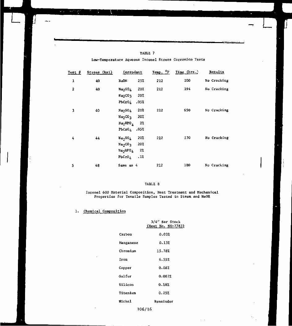
TABLE 7
Low-Temperature Aqueous Inconel Stress Corrosion Tests
Temp. °F Time (hrs.) Results
212 100 No Cracking
212 194 No Cracking
Test //
1
2
3
4
5
Stress (ksi)
40
40
40
44
48
Corrodant
NaOH
Na2S0
4
Na2C03
Na2S0
4
Na2C0
3
Na2HP0,
PbCrO4
Na2S04
Na2CO
3
Ν32ΗΡ0
4
PbCrO4
Same as
25%
20%
20%
.05%
20%
20%
2%
.05%
20%
20%
2%
.1%
4
212
212
650
170
No Cracking
No Cracking
212 180 No Cracking
TABLE 8
Inconel 600 Material Composition, Heat Treatment and Mechanical
Properties for Tensile Samples Tested in Steam and NaOH
1. Chemical Composition
3/4" Bar Stock
(Heat No. NX-7783)
Carbon
Manganese
Chromium
Iron
Copper
Sulfur
Silicon
Titanium
Nickel
0.03%
0.13%
15.78%
6.55%
0.08%
0.007%
0.18%
0.25%
Remainder
106/U.
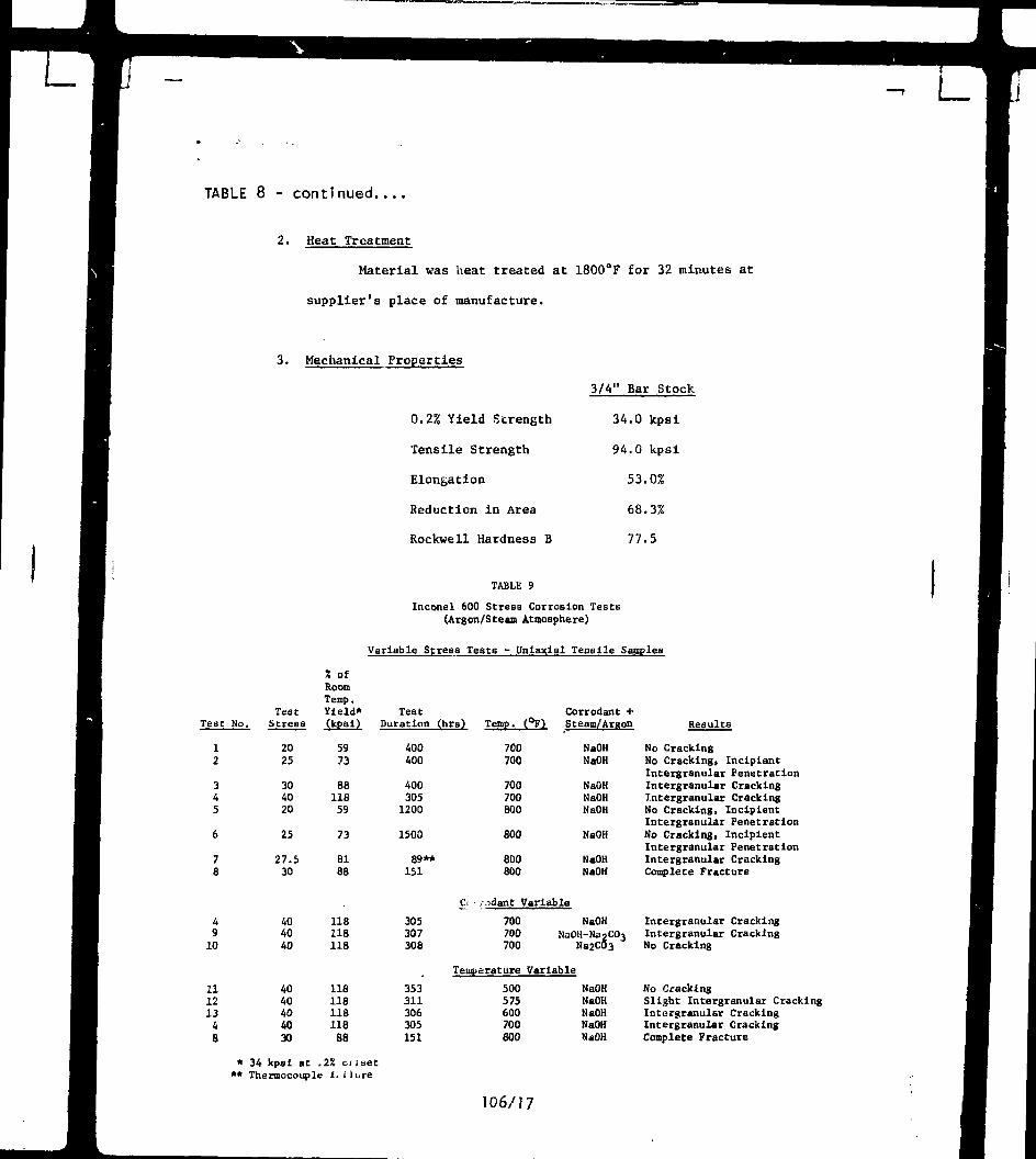
TABLE 8 - continued....
2. Heat Treatment
Material was heat treated at 1800°F for 32 minutes at
supplier's place of manufacture.
3. Mechanical Properties
0.2% Yield Strength
Tensile Strength
Elongation
Reduction in Area
Rockwell Hardness Β
3/4" Bar Stock
34.0 kpsi
94.0 kpsi
53.0%
68.3%
77.5
TABLE 9
Inconel 600 Strese Corrosion Tests(Argon/Steam Atmosphere)
Variable Stress Teats - Uniaxial Tensile Samples
Test No.
12
34
5
6
78
49
10
111213
48
TestStrese
2025
3040
20
25
27.530
4040
40
4040404030
X ofHoorn
Temp.Yield*(kpsi)
5973
8811859
73
81
88
118118118
118
118118
11888
TestDuration
400400
4003051200
1500
89**
151
305307308
353311306305
151
(hrs)
C.
Temp.
700700
700700800
800
800800
i ;idant '
700700700
Temperature
500575600700
800
Corrodant +(°F) Stearn/ArRon
NaOH
NaOH
NaOHNaOHNaOH
NaOH
NaOHNaOH
Variable
NaOH
NaOH-Na2CO
3
Na2CÖ3
Variable
NaOHNaOHNaOHNaOHNaOH
Results
No CrackingNo Cracking, IncipientIntergranular PenetrationIntergranular CrackingIntergranular CrackingNo Cracking, IncipientIntergranular PenetrationNo Cracking, IncipientIntergranular PenetrationIntergranular CrackingComplete Fracture
Intergranular CrackingIntergranular CrackingNo Cracking
No CrackingSlight Intergranular CrackingInturgranular CrackingIntergranular CrackingComplete Fracture
* 34 kpsi at .2% criset** Thermocouple f< Πι,re
106/17
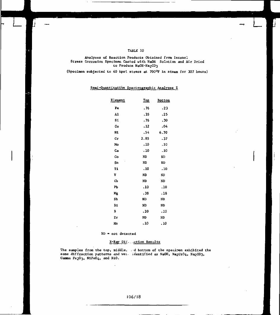
TABLE 10
Analyses of Reaction Products Obtained from InconelStress Corrosion Specimen Coated with NaOH Solution and Air Dried
to Produce Na0H-Na2C03
(Specimen subjected to 40 kpsi stress at 700°F in steam for 307 hours)
Semi-Quantitative Spectrographs Analyses %
Element
Fe
Al
Si
Cu
Ni
Cr
Mo
Ca
Co
Sn
Ti
V
Cb
Pb
Mg
Sb
Bi
Β
Zr
Mn
Top
.76
.35
.76
.12
.54
2.85
.10
.10
ND
ND
.10
ND
ND
.10
.38
ND
ND
.10
ND
.10
Bottom
.23
.25
.30
.04
6.70
.37
.10
.10
ND
ND
.10
ND
ND
.10
.18
ND
ND
.10
ND
.10
ND - not detected
X-Ray Di i . . action Results
The samples from the top, middle, : d bottom of the specimen exhibited thesame diffraction patterns and wei. identified as NaOH, Na2CrC>4, Na2C03,Gamma Fe2U3, NiFeO^, and NiO.
106/18
CROSSOVER ORCROSSUNDER PIPE
STEAMINLET
ACTIVEBELLOWS
(ALL INSTANCES OFFAILURES ARE INACTIVE BELLOWS)
wvn
INACTIVEBELLOWS(NEVER FAILS)
STEAM TOLOW PRESSURETURB11IE
2 - HvprvHcntatlve largi-dlaavtet Inconel 600 bellow» type exyanJoint foe IP-to*LP ateaai turblntd piping ètt 6QO~72Q^F· (ThLu
NOTE: THIS UNIT IS SURROUNDED BY A TIE ROD ASSKiRLYTO CONTROL AXIAL MOVEMENT
CIMUUTIVEIIUH8ER OFVSiTS
D UNFAILED
• FAILED
Τ η 9 0Τ Ι Τ ιI 7S
TO NOV.
Ftfture Ϊ - Cua.ul*tlv« cotml» by y«*r of Ueatlnghouaa turbogenerator» with
NUMbbHOF UNITSUlTHSUCCtSSFULSERVICE
i I 1 ι
NOTE. SERVICE LIFE IS ASSUMED901 OF IN-StRVICE TIKE
ι Ι ι Ι ι I t I I I ι I I
FE IN 1 0 3 "OURS
Figure <· - Service liJtitury üf aucceaeCul Inconel 600 txpaimlon joint t c t v k «In WeeUnghou»· turbogtn*retor· (a · of Hovuibar, 1974».
FAILEDIO1NTSERVICE
1) DOUBLE BARS DENOTE DATA FOR TWOJOINTS IN SAME UNIT
2) BAH HARKING DENOTES EXPOSURE TIMEIF.FOBE REPLACEMENT
2) SERVICE LIFE ASSUMED TO BE 902 OFIN-SERVICE LIFE
4) OPEN BARS UITU ARROW INDICATEFUNCTIONING REPLACEMENTUITHOUT FAILURES
UNIT IDENTIFICATION
PlKureloint bellows. Arrou denote· a i ln creek. Note pretence oi Light-o l d d I b t th l i tlbl h t h IO
106/19
Exterior surface of convolution #6 IXshowing crack in outer ply.
Interior surface of convolution i 6showing crack in the inner ply
IX
Figure 9 - i.-larged views of crach* in prociding bellows fai lure.
106/20
11/1,
Interior surface of inner ply ofconvolution #4.
Numbers indicate areas studiedwith the SEM after opening crack
1.2X
Convolution #4Note cracking occured in theinner ply only letters denoteareas studied by microscopy.
10X
Figure 10 - Inner ply cracking and fracture in the failed bellows example.
106/21
I
ιυο/ο
Etched Microsection of innerply of convolution #4(bottom radiug)
Etchant - 10% Electrolyticoxalic.
ÏOOX
Etahed microsection of outerply of convolution #4(same position as abovein cpnvolution radius)
Etchant - 10% electrolyticoxalic
100X
Figure 11 - Metallographic sections of failed bellows
106/22
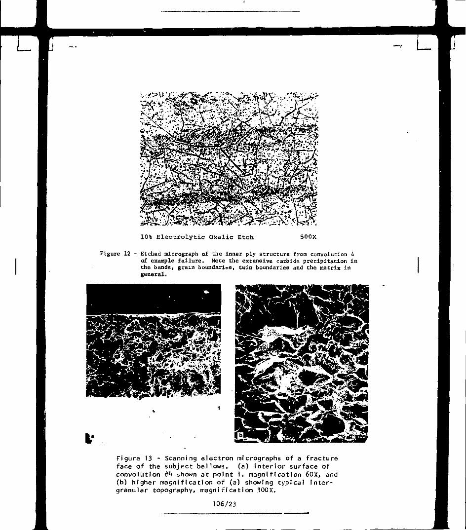
10% Electrolytic Oxalic Etch 500X
Figure 12 - Etched micrograph of the inner ply structure from convolution 4of example failure. Note the extensive carbide precipitation inthe bands, grain boundaries, twin boundaries and the matrix ingeneral.
Figure 13 - Scanning electron micrographs of a fractureface of the subject bellows. (a) interior surface ofconvolution #4 shown at point 1, magnification 60X, and(b) higher magnification of (a) showing typical inter-granular topography, magnification 300X.
106/23
L
Light Klcrognph
| t ,O.QO2"l I
Na Ion Image
c«tton (light tone) In the crack la KB*.
" θ " , 0.5 «ac 8f*,· O.S
3 5 C1", 50 eec
Figure 15 - Direct imaging mass analyses of preceding cross section through
crack showing additional species. (Indicated exposure times for
photographing the images are guides to the signal intensities.)
106/24
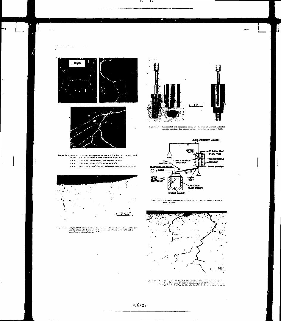
Figure 16 - Scanning electron alctograptiB of the 0.03% C heat of Inconel ueedin che high-purity utter "tre·· corrosion experiment.
A " Hill annealed, «a-recelved, not axpoaed In testΒ - Hill anne«led, after 16,000 hour· At 630°F
C - Kill annealed + ÏÜOO F/IO he, reference carbide precipitate·
Figure 1? - Un««ieabltd ind êasaabled views üf the cupped incDncJ uniaxialttnall» sptclaan foe · Ι Γ « · Β corrosion Last· In a t * u * HaOH.
UVCRMH O K I » kUCHJC)
-»TO STEAM THjVη«χ TUK
THE)W0COUn.E
FUMUCE
TEFLON «TOrK*
M U T I 0 NFLAW H O U W
HEATim liANTLt
•ati;d Jt J i . i k|>t>l In SaOtl i- eti-jra/dts.-n at SUf^F. Stvt-rt
106/25
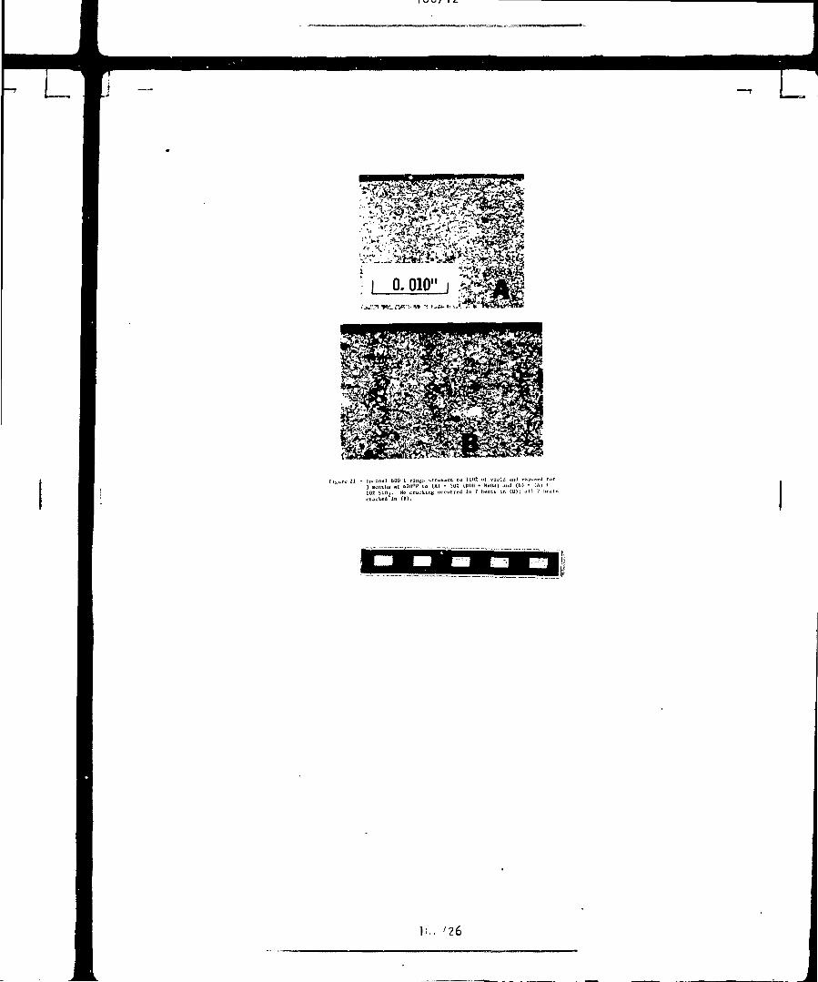
Kl,.ir« 21 - lnt-οηβΐ bOO C rlnn> !>truhfcc4 tn l lift ui vU-li! JiiJ tx|»-a«J tor3 noiului «t ö20°F to (A) - 5ut UOtl -t NuOll) and (b) · (A) i
l < . ' 2 6
j