Embed Size (px)
Citation preview

NOLTA, IEICE
Paper
Remote congestion control usingmodel-free butterfly-shaped perfect delaycompensator for active queuemanagement supporting TCP flows
Ryosuke Hotchi 1a) and Ryogo Kubo 1
1 Department of Electronics and Electrical Engineering, Keio University
3–14–1, Hiyoshi, Kohoku-ku, Yokohama-shi, Kanagawa 223–8522, Japan
Received July 9, 2018; Revised November 10, 2018; Published April 1, 2019
Abstract: This paper proposes a remote congestion controller with the butterfly-shapedperfect delay compensator (PDC) for time-delay compensation in active queue management(AQM) supporting transmission control protocol (TCP) flows. The butterfly-shaped PDC doesnot need any time-delay model of TCP/AQM network. Simulations show that the proposedcontroller with the butterfly-shaped PDC effectively stabilizes the TCP/AQM network even ifthe system includes time-varying delays.
Key Words: active queue management, TCP, time delay, control theory, QoS
1. IntroductionThe Internet is essential in the modern world, and many modern electronic devices use the Internetto communicate with people and devices around the world. Currently, the most commonly usedcommunication protocol is the transmission control protocol (TCP). In communication via loss-basedTCPs, the receiver host detects packet loss as a sign of network congestion and notifies the sender hostof the presence of congestion. Upon receiving this notification, the sender host scales down the sendingwindow size, resulting in reduced communication speed in order to control congestion. This procedureis applied to each and every sender host. Due to this mechanism, a large quantity of packets wouldbe dropped if serious network congestion occurs, which leads to the situation that many TCP flowssharing the same network reduce their window size, thus sharing the network with low throughput.This phenomenon is called global synchronization, and this greatly reduces communication efficiency.Since the number of network-connected devices is continuing to increase, congestion of network flowshas been a serious problem.
A control system called active queue management (AQM) is utilized in order to avoid seriousnetwork congestion that leads to global synchronization in TCP flows. The AQM discards packetsin the buffer of routers before congestion occurs. Many AQM controllers have been proposed. Floydet al. [1] proposed the random early detection (RED) to randomly discard packets with a drop
157
Nonlinear Theory and Its Applications, IEICE, vol. 10, no. 2, pp. 157–172 c©IEICE 2019 DOI: 10.1587/nolta.10.157

probability determined according to the average queue length. Hollot et al. [2] designed the linearTCP/AQM control system on the basis of control theory.
As an application of RED based on control theory, a system to control the queue length usinga proportional-integral-derivative (PID) controller was proposed in [3]. There are many PID con-troller variations, such as proportional-integral (PI) controller [4] and proportional-derivative (PD)controller [5]. These controllers are widely used in practice since their implementation is relativelysimple. Some studies on AQM controllers have focused on using artificial intelligence, such as neuralnetworks [6] and fuzzy logic [7, 8]. However, implementation of these algorithms requires the presenceof an expert, thus they are relatively difficult to utilize [9]. A robust AQM controller using a distur-bance observer (DOB) was proposed in [10, 11] as an extended research topic focusing on the use ofa PD controller.
Routers which utilize an AQM controller are generally connected to one another, and congestioncontrol in one router may also affect congestion control in the other. More efficient congestion controlcould be expected if information flow between routers is collected in one place and controlled coop-eratively. Chibana et al. [12] proposed a remote congestion controller to enable cooperative AQMof multiple routers and flexible AQM taking traffic conditions in the entire network into account.However, each router must be remotely controlled via the network simultaneously in order to realizesuch a system. Such a control system, i.e., a system that forms a control loop via the network, iscalled a networked control system (NCS). Network-induced delay is one of the major factors greatlyaffecting the performance and stability of the NCS [13]. If a feedback loop is formed via the Internet,its network-induced delay varies randomly depending on the number of hardware units and end-usersconnected to the Internet. This random network delay is unpredictable, and remote control systemseasily become unstable due to random network delay [14]. Many studies have attempted to addressthe effect of network-induced delay in the NCSs [15, 16].
To compensate the network-induced delay in the TCP/AQM network, the Smith predictor (SP)and adaptive SP (ASP) have been proposed. The existing works aim at compensating the round-tripdelay between a server and a client. Li et al. [17] proposed an AQM scheme using a PI controller withthe SP. The ASP can compensate the effect of fluctuating delay as long as it can be measured [18],while the SP compensates only constant delay. Ohsaki et al. [19] has proposed an AQM scheme usingthe RED with the ASP. However, the existing works have not discussed the time-varying networkdelay between the remote congestion controller and router, as shown in [12]. In addition, the SPand ASP need the time-delay model or time-delay measurement, which leads to system instability orimplementation complexity.
This paper proposes a remote TCP/AQM congestion control system using a model-free time-delaycompensator. In this research, we focus on the AQM based on control theory due to its simpleimplementation, and use a PID controller for the AQM congestion controller. A butterfly-shapedperfect delay compensator (PDC) [20] is adopted as a time-delay compensator. The butterfly-shapedPDC was originally proposed for time-delay compensation in networked motion control systems andcan sweep out time-delay elements from a feedback loop without any time-delay model. In order toapply the butterfly-shaped PDC to the TCP/AQM network, we define a controller model on a plantside and consider the model mismatch between the controller model and an original controller on aremote controller side. The effectiveness of the proposed controller is validated from simulations usingtime-varying network delays.
This paper is organized as follows. The following section describes a TCP/AQM network model.Section 3 presents a PID-based controller as a conventional AQM controller. Section 4 proposes thebutterfly-shaped PDC for use in a TCP/AQM network. Section 5 show the total control system anddiscusses the model mismatch in the butterfly-shaped PDC. Simulation results are shown in Section6. Finally, our conclusion is presented in Section 7.
2. TCP/AQM network model
A linear TCP/AQM network model proposed by Hollot et al. [2] is utilized in this paper. The
158

linear TCP/AQM network model was designed by linearizing a nonlinear TCP/AQM network modelproposed by Misra et al. [21]. The derivation of the linear TCP/AQM model is shown in this section.
2.1 Nonlinear TCP/AQM network modelThe nonlinear TCP/AQM network model is shown in Eqs. (1) and (2)
W (t) =1
R(t)− W (t)W (t − R(t))
2R(t − R(t))p(t − R(t)), (1)
q(t) = −C(t) +N(t)R(t)
W (t). (2)
The variables in Eqs. (1) and (2) are defined as follows:
W (t) .= TCP window size,
q(t) .= queue length,
R(t) .= round-trip time (RTT)(
� q(t)C(t)
+ Tp
),
C(t) .= bottleneck link capacity,
Tp.= propagation delay,
N(t) .= the number of TCP sessions,
p(t) .= packet drop probability while p(t) ∈ [0, 1].
2.2 Linear TCP/AQM network modelIn order to linearize Eqs. (1) and (2), it was assumed that the TCP session number N(t) and linkcapacity C(t) are constant, i.e., N(t) ≡ N and C(t) ≡ C. In addition, the operating point whereW = 0 and q = 0 is defined as (W0, p0, q0, R0). From these assumptions, the following equations arederived:
W 20 p0 = 2, (3)
W0 =CR0
N, (4)
R0 =q0
C+ Tp. (5)
To proceed with linearization, the dependence of the time delay argument t−R(t) on queue lengthq(t) is ignored and assumed to be fixed to t − R0. On the other hand, the dependence of RTT R(t)on queue length q(t) in the dynamic parameters is retained. As a result, the simplified dynamics areobtained as follows:
W (t) =1
q(t)C + Tp
− W (t)2
W (t − R0)q(t−R0)
C + Tp
p(t − R0), (6)
q(t) = −C +N
R(t)W (t). (7)
Next, the right-hand sides of Eqs. (6) and (7) are defined as Eqs. (8) and (9)
f (W (t), WR(t), q(t), qR(t), pR(t)) =1
q(t)C + Tp
− W (t)WR(t)
2(
qR(t)C + Tp
)pR(t), (8)
g (W (t), q(t)) = −C +N
q(t)C + Tp
W (t), (9)
where WR(t) .= W (t − R0), qR(t) .= q(t − R0), and pR(t) .= p(t − R0).The partial derivatives of f and g at this operating point (W0, p0, q0, R0) can be derived by recalling
the operating point relationships shown in Eqs. (3) and (4). From those partial derivatives, Eqs. (6)and (7) can be linearized as follows:
159

Fig. 1. Linearized TCP/AQM network model.
Fig. 2. Simplified linear TCP/AQM network model.
δW (t) = − N
R20C
(δW (t) + δW (t − R0)) − 1R2
0C(δq(t) − δq(t − R0)) − R0C
2
2N2δp(t − R0), (10)
δq(t) =N
R0δW (t) − 1
R0δq(t), (11)
where δW = W − W0, δq = q − q0, and δp = p − p0. A block diagram of the linearized dynamics isshown in Fig. 1.
Hollot et al. continued to simplify these dynamics by dividing the dynamics into a nominal modeland modeling error. A simplified block diagram is shown in Fig. 2. The modeling error Δ(s) is definedas Eq. (12)
Δ(s) .=2N2s
R20C
3(1 − e−sR0). (12)
Finally, from the fact that the modeling error Δ(s) has extremely small gain, by excluding Δ(s)from Fig. 2, the TCP/AQM network model for the controller design can be derived as shown inFig. 3. The transfer function C(s) denotes the AQM controller for the TCP/AQM network. TheAQM controller uses the queue length information in order to calculate the packet drop probability.The transfer function P (s) is a combination of the nominal window dynamics, queue dynamics, theblock element in between these two ( N
R0), and the minus sign before the window dynamics, as shown
in Fig. 2. The transfer function P (s) can be written as Eq. (13)
160

Fig. 3. TCP/AQM control system.
Fig. 4. TCP/AQM control system with the inertia model.
P (s) = −C2
2N(s + 2N
R2C
) (s + 1
R
) . (13)
3. AQM using PID controller
The TCP/AQM control system using a conventional PID controller is presented in this section.
3.1 Nominal TCP/AQM network modelIn order to simplify the design of the AQM controller, we utilize a nominal TCP/AQM networkmodel [10]. The nominal TCP/AQM network model Pn(s) is defined as Eq. (14)
Pn(s) = − C2
2Nn
1s2
, (14)
where Nn denotes the nominal number of TCP sessions. In addition, the inertia model in TCP/AQMnetwork dynamics Mn is defined as Eq. (15)
Mn = −2Nn
C2. (15)
From Eqs. (14) and (15), the following relationship between Pn(s) and Mn can be derived:
Pn(s) =1
Mns2. (16)
The linear TCP/AQM network model shown in Fig. 3 can be converted to Fig. 4 by using thisinertia model. In Fig. 4, ddp denotes the modeling error of the TCP/AQM network in the dimensionof packet drop probability. The output of the controller is redefined as δpref in the TCP/AQM controlsystem with the inertia model.
3.2 Controller designThe controller C(s) includes the PID controller and inertia model. The PID controller is implementedin order to converge the queue length output q to the target queue length qcmd. In other words, q0
defined in Section 2 is redefined as q0 = qcmd. The acceleration reference value of the queue lengthδqref can be derived as Eq. (17)
161

Fig. 5. Block diagram of a general NCS.
δqref = −(Kp + Ki1s
+ Kds)δq, (17)
where Kp, Ki, and Kd denote the proportional gain, integral gain, and derivative gain, respectively.The output of the PID controller δqref can be converted to δpref as Eq. (18)
δpref = Mnqref . (18)
4. Time-delay compensation using butterfly-shaped PDC
A butterfly-shaped PDC is utilized to compensate time delays in the TCP/AQM network. Thebutterfly-shaped PDC is a model-free delay compensator, and we have implemented it as a networkdelay compensator in a proposed remote AQM control system. In this section, the general character-istics of a control system including network delay are explained, and the operating mechanism of thebutterfly-shaped PDC is presented.
4.1 NCSThe NCS is a control system that has a feedback loop going through the network. The implementationcost of the control system would be greatly reduced if a commercial network is integrated in order toconstruct the NCS. The proposed remote AQM control system is an NCS. Network-induced delay isunavoidable since the NCS sends the control signal through the network. In addition, when consideringthe usage of a commercial network, network delay would not be constant and may fluctuate randomly.This unpredictable network delay is known to greatly affect the performance of the NCS.
Figure 5 shows the block diagram of the general NCS, which is only constructed from the controllerGc(s), the plant Gp(s), forward network delay t1, and feedback network delay t2. R(s) and Y (s) denotethe input and output signals, respectively. If the network has no delay, i.e., t1 = t2 = 0, the transferfunction for the entire block diagram is denoted as Eq. (19)
GwoNET (s) =Y (s)R(s)
=Gc(s)Gp(s)
1 + Gc(s)Gp(s). (19)
The transfer function GwoNET is an ideal transfer function for an NCS.The NCS transfer function that includes network delay, i.e., t1 �= 0 and t2 �= 0, is defined as Eq. (20)
GwNET (s) =Y (s)R(s)
=Gc(s)Gp(s)e−t1s
1 + Gc(s)Gp(s)e−(t1+t2)s. (20)
The transfer function of GwNET shown in Eq. (20) is clearly more complicated compared to that ofGwoNET shown in Eq. (19). In addition, GwNET includes a time-delay element in the denominator. Itis known that if the denominator of the transfer function includes time-delay elements, the design ofa robust controller would become difficult, and the robustness of the entire control system degrades.Due to this fact, many recent studies have focused on the time-delay compensation method.
4.2 Butterfly-shaped PDCThe butterfly-shaped PDC is a model-free time-delay compensator. The term model-free means thatthis compensator does not require any information regarding the time delays. Figure 6 is the block
162

Fig. 6. Control system with the butterfly-shaped PDC.
Fig. 7. Controller implementation of the butterfly-shaped PDC.
diagram of the butterfly-shaped PDC originally proposed by Lai et al. [20]. Figure 7 shows the blockdiagram equivalent to Fig. 6 with the controller Gc(s) placed on the remote controller side. As shownin Fig. 7, in the PDC-based networked control systems, the controller Gc(s) has to be implemented onboth the remote controller and plant sides. The system shown in Fig. 7 was proposed for networkedmotion control. The controllers on the remote controller and plant sides are defined as an originalcontroller and a controller model, respectively.
In the motion control systems, the nominal plant model is generally time-invariant as long asthe plant system is not changed dynamically in operation. On the other hand, the nominal plantmodel of the TCP/AQM network used in controller design should be frequently changed becausethe plant system, i.e., the amount of network traffic through routers, may fluctuate in operation.However, the controller model on the plant side cannot be updated so frequently in operation becausethe controller model is implemented to the router’s firmware, whereas the software-based originalcontroller is implemented to a remote server.
Figure 8 shows the proposed butterfly-shaped PDC scheme. The controller model Gc(s) on theplant side shown in Fig. 7 is replaced by Gm(s). In our proposed PDC-based system shown in Fig. 8,the original controller on the remote controller side Gc(s) and the controller model on the plant sideGm(s) are defined as different transfer functions to discuss their model mismatch, which would nothave occurred in motion control, as assumed in [20].
In this section, we confirm that the block diagram shown in Fig. 8 compensates network delay.First, the input and output sides of the plant butterfly element, each denotes as Up(s) and Yr(s),respectively, can be rewritten as follows:
Up(s) = Ur(s) − Gm(s)Yp(s), (21)
Yr(s) = Yp(s) + Gm−1(s)Up(s). (22)
Since the transfer function from Up(s) to Yp(s) can be written as Eq. (23), the transfer function fromUr(s) to Yr(s) can be derived as Eq. (24):
Yp(s)Up(s)
= Gp(s), (23)
163

Fig. 8. Proposed butterfly-shaped PDC scheme considering controller modelmismatch.
Yr(s)Ur(s)
=Yp(s) + Gm
−1(s)Up(s)Up(s) + Gm(s)Yp(s)
=Gp(s) + Gm
−1(s)1 + Gm(s)Gp(s)
. (24)
The forward and feedback signals right after the network, each denotes as Ur(s) and Yl(s), can bewritten as shown in Eqs. (25) and (26), respectively.
Ur(s) = Ul(s)Gc(s)e−t1s (25)
Yl(s) = Yr(s)e−t2s (26)
From Eqs. (24)–(26), the transfer function from Ul(s) to Yl(s) can be derived as Eq. (27)
Yl(s)Ul(s)
=Yr(s)e−t2sGc(s)e−t1s
Ur(s)
=(Gp(s) + Gm
−1(s))Gc(s)e−(t1+t2)s
1 + Gm(s)Gp(s). (27)
The forward and feedback output signals at the left hand side butterfly element, each denotes as Ul(s)and Yc(s), can be written as Eqs. (28) and (29), respectively.
Ul(s) = Uc(s) + Yc(s) (28)
Yc(s) = Yl(s) + Uc(s) (29)
By combining these equations, Eqs. (30) and (31) can be obtained.
2Uc(s) = Ul(s) − Yl(s) (30)
2Yc(s) = Yl(s) + Ul(s) (31)
From these equations and Eq. (27), the transfer function from Uc(s) to Yc(s) can be derived as Eq. (32)
Yc(s)Uc(s)
=Ul(s) + Yl(s)Ul(s) − Yl(s)
=(1 + Gm(s)Gp(s)) +
(Gp(s) + Gm
−1(s))Gc(s)e−(t1+t2)s
(1 + Gm(s)Gp(s)) −(Gp(s) + Gm
−1(s))Gc(s)e−(t1+t2)s
. (32)
The forward input signal at the left hand side butterfly element Uc(s) can be expressed as Eq. (33)
Uc(s) = R(s) − Yc(s). (33)
By combining Eqs. (32) and (33), the transfer function from the input of the control system R(s) toYc(s) can be derived as Eq. (34)
164

Yc(s)R(s)
=Ul(s) + Yl(s)
2Uc(s)
=(1 + Gm(s)Gp(s)) +
(Gp(s) + Gm
−1(s))Gc(s)e−(t1+t2)s
2 (1 + Gm(s)Gp(s)). (34)
Then, by utilizing the relationship between Yc(s) and Yp(s) shown in Eq. (35) and the relationshipbetween Up(s) and Yp(s) shown in Eq. (36), Yp(s) can be expressed as Eq. (37).
Yc(s) = Uc(s) + (Up(s)Gm(s) + Yp(s)) e−t2s (35)
Up(s) = Gp−1(s)Yp(s) (36)
Yp(s) =(Yc(s) − Uc(s))(
Gp−1(s)Gm(s) − 1
)e−t2s
(37)
Using Eq. (37), the transfer function from R(s) to Yp(s) can be derived as Eq. (38)
Yp(s)R(s)
=Gc(s)Gm
−1(s) − Gc(s)Gp(s)1 + Gm(s)Gp(s)
· 1Gp
−1(s)Gm−1(s) − 1
· e−t1s
=Gm(s)Gp(s)
1 + Gm(s)Gp(s)· 1Gm(s)Gp(s)
· Gc(s)Gm−1(s) − Gc(s)Gp(s)
Gp−1(s)Gm
−1(s) − 1· e−t1s
=Gm(s)Gp(s)
1 + Gm(s)Gp(s)· Gc(s)Gm
−1(s) − Gc(s)Gp(s)Gm(s)Gm
−1(s) − Gm(s)Gp(s)· e−t1s
=Gm(s)Gp(s)
1 + Gm(s)Gp(s)· Gc(s)Gm(s)
· e−t1s. (38)
It is clear that Yp(s) = Y (s), thus the transfer function for the total networked control system usingPDC GPDC(s) can be expressed as Eq. (39)
GPDC(s) =Y (s)R(s)
=Gm(s)Gp(s)
1 + Gm(s)Gp(s)· Gc(s)Gm(s)
· e−t1s. (39)
The final transfer function shown in Eq. (39) consists of an ideal transfer function using Gm(s), modelmismatch between Gm(s) and Gc(s), and pure forward delay t1.
The controller model Gm(s) is generally designed identical to the original controller Gc(s). Byassuming that Gm(s) = Gc(s), Eq. (39) can be rewritten as Eq. (40)
GPDCmatch(s) =Gc(s)Gp(s)
1 + Gc(s)Gp(s)· e−t1s. (40)
As Eq. (40) shows, the control system using a butterfly-shaped PDC successfully compensates theeffect of the network delay.
5. Total control system and model mismatchAs mentioned in Section 4, the proposed control system includes an original controller and controllermodel, and their mismatch may occur. This section presents the block diagram of the proposedremote AQM control system with a butterfly-shaped PDC, and discuss the model mismatch.
5.1 Proposed remote AQM control system using butterfly-shaped PDCFigure 9 shows the proposed remote AQM control system using a butterfly-shaped PDC. The specificequations describing the transfer function of the original controller Gc(s) and the controller modelGm(s) are as shown in Eqs. (41) and (42), respectively.
Gc(s) = Mnc
(Kp + Ki
1s
+ Kds
)(41)
Gm(s) = Mnm
(Kp + Ki
1s
+ Kds
)(42)
In Eqs. (41) and (42), Mncand Mnm
denote the inertia models used for designing the original controllerand the controller model, respectively.
165

Fig. 9. Proposed remote AQM control system using butterfly-shaped PDC.
5.2 Model mismatchAs shown in Eq. (40), if the original controller and controller model are identical, the transfer functionof the total control system can be constructed only from the ideal transfer function and pure forwarddelay. However, it is possible that the original controller and the controller plant may differ in reality.We suppose that the controller model is implemented in the bottleneck router’s firmware in actualimplementation of this system. Thus, the implemented controller model may be updated periodically,but not in real time.
As shown in Eq. (15), the inertia model Mn is defined by the bottleneck link capacity C and thenominal number of TCP sessions Nn. In addition, both the original controller and controller modelinclude their own individual inertia models. Therefore, the equations defining Mnc
and Mnmcan be
rewritten as Eqs. (43) and (44), respectively.
Mnc= −2Nnc
C2(43)
Mnm= −2Nnm
C2(44)
In Eqs. (43) and (44), Nncand Nnm
denote the nominal number of TCP sessions used to designoriginal controller and controller model, respectively.
The original controller and controller model both utilize the same PID controller gain parameters,and it is not likely that the bottleneck link capacity changes over time. Therefore, the mismatchbetween the original controller and controller model may occur when the values of Nnc
and Nnmare
not equal. As shown in Eq. (39), the model mismatch ratio directly affects the transfer function ofthe whole system proportionally. Therefore, the design of the original controller must be adjusted tolower the proportional effect due to model mismatch while still maintaining the overall performanceof the TCP/AQM congestion control system.
6. SimulationThis section shows simulation results that confirm the validity of the proposed butterfly-shaped PDCand the effect of model mismatch.
6.1 Simulation setupSimulations were performed using the network simulator ns-2 in order to validate the proposed con-gestion controller. The dumbbell shaped network topology shown in Fig. 10 was utilized in thesimulations. The value of the number of TCP sessions N varies depending on the simulation purpose,which was set to 100 if not specified. The parameters used in the simulations are shown in Table I.The parameters used to design the PID controller are shown in Table II. Control parameters wereset by reference to [22]. The values of nominal number of TCP sessions used to design the originalcontroller Nnc
and the controller model Nnmvary depending on the simulation purpose, which were
set to N if not specified.
166

Fig. 10. Simulation topology.
Table I. Simulation parameters.
Sender side link capacity 10 MbpsReceiver side link capacity 10 MbpsBottleneck link capacity C 10 Mbps
Packet size 1000 bytesSimulation duration time 200 s
Packet drop probability operating point p0 0Router buffer size 200 packets
Target queue length qcmd 100 packetsControl period 0.001 s
Table II. Control parameters.
Kp Proportional gain 900Ki Integral gain 700Kd Derivative gain 55gdif Cut-off frequency of pseudo-differential 50 rad/s
Fig. 11. Simulation results (t1 = t2 = 50 ms).
6.2 Compensation of identical forward and feedback time delaysSimulation results using the matching controller model with forward network delay t1 equal to feedbacknetwork delay t2 are shown in this subsection. Figure 11 shows the simulation results when t1 = t2 =50 ms. The figure shows the results of the system without the butterfly-shaped PDC, referred aswoPDC, and with the butterfly-shaped PDC, referred as wPDC. From the simulation results, wecan see that the oscillation in the woPDC is larger than that in the wPDC. This indicates that thenetwork delay directly affects the stability of the system, and the PDC effectively compensates thisnetwork delay.
Figure 12 shows the standard deviation (SD) of the queue length for various forward and feedback
167

Fig. 12. Comparison of SD values (t1 = t2).
Fig. 13. Simulation results (t1 �= t2).
delays. The SD values were calculated using all simulation results after 5 s out of the total simulationduration of 200 s, in order to avoid the effect of overshoot occurring at the start of the simulations.A larger SD value generates a larger queue length oscillation. We can see from Fig. 12 that the SDis larger when network delay is larger without the PDC. However, this effect can be compensatedand the SD values can be kept at a relatively lower value by implementing PDC to the system, evenwith a large network delay. The effectiveness of the PDC in compensating the identical forward andfeedback network delays can be verified from these simulation results.
6.3 Compensation of different forward and feedback time delaysThis subsection shows the simulation results using the matching controller model when t1 and t2 aredifferent. Figure 13(a) shows the simulation results when t1 = 20 ms and t2 = 60 ms. Figure 13(b)shows the simulation results when t1 = 60 ms and t2 = 20 ms. Figure 14 shows the SD value forvarious t2 values when t1 = 20 ms and t1 = 60 ms. From these simulation results, we can see that theproposed control system utilizing the PDC can compensate network delays, even if the forward andfeedback delays are not identical. The relationship between forward and feedback delays also did notaffect the PDC efficiency.
6.4 Compensation of fluctuating time delaysThis subsection shows the simulation results using the matching controller model while t1 and t2 aresimultaneously fluctuating. Figure 15 shows two types of delay fluctuations used in the simulation.Figure 16 shows the simulation results while t1 and t2 are fluctuating, as shown in Fig. 15. Fromthese simulation results, we can see that the PDC successfully compensates for network delays, evenif the network delays fluctuate.
168
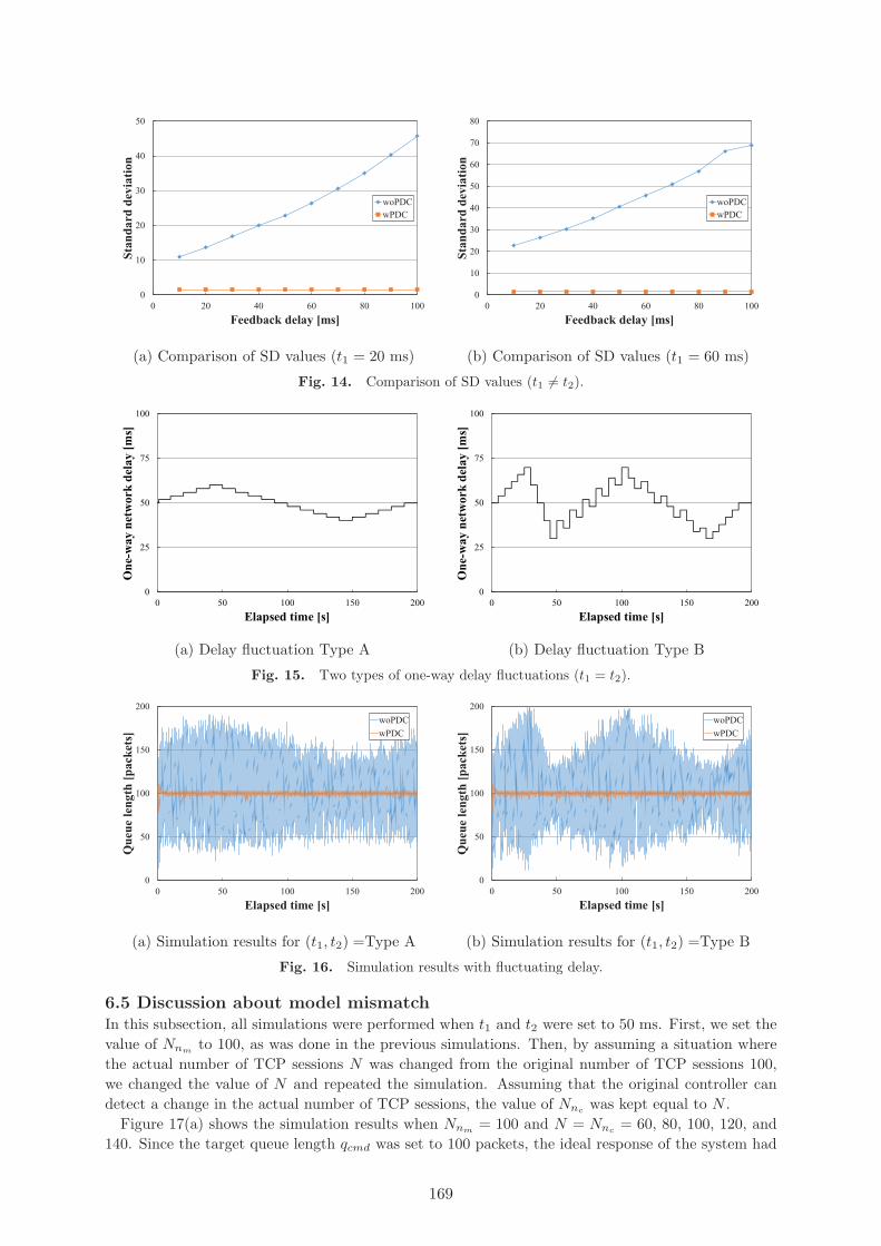
Fig. 14. Comparison of SD values (t1 �= t2).
Fig. 15. Two types of one-way delay fluctuations (t1 = t2).
Fig. 16. Simulation results with fluctuating delay.
6.5 Discussion about model mismatchIn this subsection, all simulations were performed when t1 and t2 were set to 50 ms. First, we set thevalue of Nnm
to 100, as was done in the previous simulations. Then, by assuming a situation wherethe actual number of TCP sessions N was changed from the original number of TCP sessions 100,we changed the value of N and repeated the simulation. Assuming that the original controller candetect a change in the actual number of TCP sessions, the value of Nnc
was kept equal to N .Figure 17(a) shows the simulation results when Nnm
= 100 and N = Nnc= 60, 80, 100, 120, and
140. Since the target queue length qcmd was set to 100 packets, the ideal response of the system had
169

Fig. 17. Simulation results with mismatch (Nnm= 100).
Fig. 18. Simulation results with mismatch (Nnm= 80, 120).
its average queue length close to 100 packets. However, as Fig. 17(a) shows, the average queue lengthdiffered from the ideal response when mismatch error between Nnm
and Nnc= N occured. The
stability of the system, i.e., the queue length oscillation, remained nearly constant, even if mismatchoccurred. Thus, the effect of model mismatch can be discussed by focusing on the average queuelength.
Figure 17(b) shows the results of average queue lengths when Nnm= 100, and N and Nnc
were setto 60, 80, 100, 120, or 140. The average queue lengths were calculated using all simulation resultsafter 5 s out of the total simulation duration of 200 s in order to avoid overshoot occurring at thebeginning of the simulations. As Fig. 17(b) shows, the average queue length would be nearly equalto 100 packets when Nnc
= 100, which was equal to Nnm. Therefore, it can be assumed that when
Nnc= Nnm
, the system will return the ideal average queue length.The same simulations with Nnm
= 80 and 120 were performed in order to confirm this assump-tion. Figures 18(a) and 18(b) show the results of average queue lengths when Nnm
= 80 and 120,respectively. In Fig. 18(a), the average queue length is nearly equal to 100 packets when Nnc
= 80,which is equal to Nnm
. In Fig. 18(b), the average queue length is nearly equal to 100 packets whenNnc
= 120, which is equal to Nnm. The value of N in both figures does not clearly affect the average
queue length. These simulation results confirm that Nnc= Nnm
is suitable, regardless of the value ofN .
7. ConclusionThis paper proposed a remote congestion controller with the butterfly-shaped PDC for time-delaycompensation in the TCP/AQM network. The simulation results showed that the proposed controllerwith the butterfly-shaped PDC effectively stabilized the TCP/AQM network even if the system in-
170

cluded time-varying delays. The proposed congestion control system with PDC may have a modelmismatch between the actual system and the controller model, and the ratio of controller model andoriginal controller proportionally affects the output of the system. It was verified that by matchingthe parameters of the original controller to that of the controller model, the effect of model mismatchcan be excluded even if the parameters do not match that of the actual system. Our future worksinclude considering the situation that multiple routers are controlled simultaneously with differentcontroller models.
Acknowledgments
This work was supported in part by JSPS KAKENHI Grant Numbers 18K11275 and 18H03236.
References[1] S. Floyd and V. Jacobson, “Random early detection gateways for congestion avoidance,”
IEEE/ACM Transactions on Networking, vol. 1, no. 4, pp. 397–413, August 1993.[2] C.V. Hollot, V. Misra, D. Towsley, and W. Gong, “Analysis and design of controllers for
AQM routers supporting TCP flows,” IEEE Transactions on Automatic Control, vol. 47, no. 6,pp. 945–959, June 2002.
[3] A. Haider, H. Sirisena, and K. Pawlikowwski, “PID based congestion control algorithms forAQM routers supporting TCP/IP flows,” IEICE Transactions on Communications, vol. E87-B,no. 3, pp. 548–555, March 2004.
[4] M.Y. Waskasi, M.J. Yazdanpanah, and N. Yazdani, “A new active queue management algorithmbased on neural networks PI,” Proceedings of the 16th IFAC Triennial World Congress, vol. 38,no. 1, pp. 1–6, July 2005.
[5] J. Sun, G. Chen, K. Ko, S. Chan, and M. Zukerman, “PD-controller: A new active queue man-agement scheme,” Proceedings of the IEEE Global Telecommunications Conference (GLOBE-COM ’03), pp. 3103–3107, December 2003.
[6] H.C. Cho, M.S. Fadali, and H. Lee, “Neural network control for TCP network congestion,”Proceedings of the 2005 American Control Conference (ACC ’05), vol. 5, pp. 3480–3485, June2005.
[7] M.H.Y. Moghaddam, “A fuzzy active queue management mechanism for Internet congestioncontrol,” Proceedings of the Third International Workshop on Advanced Computational Intelli-gence (IWACI ’10), pp. 203–208, August 2010.
[8] Y.H. Aoul, A. Nafaa, D. Negru, and A. Mehaoua, “FAFC: fast adaptive fuzzy AQM con-troller for TCP/IP networks,” Proceedings of the IEEE Global Telecommunications Conference(GLOBECOM ’04), vol. 3, pp. 1319–1323, November 2004.
[9] N.E. Fezazi, S.B. Alaoui, F.E. Haoussi, E.H. Tissir, and T. Alvarez, “A dynamic anti-windupAQM for congestion control in Internet,” Proceedings of the 2016 IEEE/ACS 13th InternationalConference of Computer Systems and Applications (AICCSA ’16), pp. 1–6, November 2016.
[10] R. Kubo, J. Kani, and Y. Fujimoto, “Advanced Internet congestion control using a disturbanceobserver,” Proceedings of the IEEE Global Communications Conference (GLOBECOM ’08),pp. 1–5, December 2008.
[11] H. Chibana, M. Tadokoro, D. Murayama, K. Suzuki, and R. Kubo, “Robustness evaluation ofdisturbance observer-based active queue management supporting TCP flows,” IEICE Commu-nications Express, vol. 3, no. 10, pp. 311–316, October 2014.
[12] H. Chibana, M. Yoshino, M. Tadokoro, D. Murayama, K. Suzuki, and R. Kubo, “Disturbance-observer-based active queue management with time delay using software-defined networkingcontroller,” Proceedings of the 41st Annual Conference of the IEEE Industrial Electronics Society(IECON ’15), pp. 1049–1054, November 2015.
[13] F.L. Lian, J.R. Moyne, and D.M. Tilbury, “Performance evaluation of control networks: Eth-ernet ControlNet and DeviceNet,” IEEE Control Systems Magazine, vol. 21, no. 1, pp. 66–83,February 2001.
171
[14] J. Baillieul and P.J. Antsaklis, “Control and communication challenges in networked real-timesystems,” Proceedings of the IEEE, vol. 95, no. 1, pp. 9–28, Janury 2007.
[15] W. Zhang, M.S. Branicky, and S.M. Phillips, “Stability of networked control systems,” IEEEControl Systems Magazine, vol. 21, no. 1, pp. 84–99, February 2001.
[16] E. Joelianto, “Networked control systems: Time delays and robust control design issues,” Pro-ceedings of the 2nd International Conference on Instrumentation Control and Automation (ICA’11), pp. 16–25, November 2011.
[17] Y. Li, K. Ko, and G. Chen, “A Smith predictor-based PI-controller for active queue manage-ment,” IEICE Transactions on Communications, vol. E88-B, no. 11, pp. 4293–4300, November2005.
[18] A. Bahill, “A simple adaptive Smith-predictor for controlling time-delay systems: A tutorial,”IEEE Control Systems Magazine, vol. 3, no. 2, pp. 16–22, May 1983.
[19] H. Ohsaki, H. Yamamoto, and M. Imase, “SPRED: Active queue management mechanism forwide-area networks,” Proceedings of the 2007 International Symposium on Applications and theInternet (SAINT ’07), January 2007.
[20] C.L. Lai and P.L. Hsu, “The butterfly-shaped feedback loop in networked control systems forthe unknown delay compensation,” IEEE Transactions on Industrial Informatics, vol. 10, no. 3,pp. 1746–1754, August 2014.
[21] V. Misra, W. Gong, and D. Towsley, “A fluid-based analysis of a network of AQM routers sup-porting TCP flows with an application to RED,” ACM SIGCOMM Computer CommunicationReview, vol. 30, no. 4, pp. 151–160, October 2000.
[22] R. Kubo, J. Kani, and Y. Fujimoto, “Congestion control in TCP/AQM networks using a dis-turbance observer,” IEEJ Transactions on Industry Applications, vol. 129, no. 6, pp. 541–547,June 2009. (in Japanese)
172