Embed Size (px)
Citation preview

Paper Tape Motion Timer.....10/24/07 1Don Rathjen....Exploratorium Teacher Institute....3601 Lyon St., San Francisco, CA [email protected]© 2007 Exploratorium, www.exploratorium.edu
Paper Tape Motion TimerTiming is Everything!
Figure 1
A strip of adding machine paper tape is passed underneath the tip of a marking pen that is being repeatedlybumped by a wooden dowel mounted off-center on the spinning shaft of an electric motor operating at constantspeed. Every time the pen is bumped, it makes a mark on the paper tape. Since the motor speed is constant,the time interval between marks is constant. If the paper is dragged rapidly, the marks on the paper are farapart; if the paper is dragged slowly, the marks are close together. The resulting record of marks on the tapecan be used to tell the story of the motion, create graphical representations of the motion, and obtain informationabout displacement, velocity and acceleration for things like toy cars, falling objects, etc.
Materials• wood base, 3/4 in x 5 1/2 in x 9 in (in Home Depot terms, a piece of "1x6" pine shelving that is 9 inches long)• 4 wooden craft sticks (popsicle stick size) • hot glue gun and hot glue sticks• 2 wooden craft sticks (tongue depressor size) • paper adding machine tape, 2 1/4 in wide• motor, dc, (e.g., Radio Shack 273-223, 1.5-3 v, or Kelvin 850647 1.5-6 v – Kelvin is cheaper, but Radio Shack
is more accessible)• 2 alligator clip leads -- e.g., Kelvin 330114, 10/pack, or Radio Shack 278-1157, 8/pack – or can improvise
by using ordinary hookup wire (approximately #20 or #22), twisting ends to make connections, anddevising some way to conveniently connect and disconnect the motor
• spring clip broom holder (available from Home Depot and other home improvement and hardware stores)• machine screw, 6-32 x 1/2 in • stop nut w/ nylon insert, 6-32• screwdriver, Phillips • 2 washers, ordinary zinc-plated steel, 1/4 in• electric drill • drill bits -- 3/16 in, 9/64 in, #50 wire gauge (1.78 mm)• 3 bottle caps from 2-liter plastic soda bottle, or other bottles with same kind of cap -- the caps should be the
harder, rigid plastic kind, not the softer, more flexible kind typically found on 500 mL water bottles• 1 bottle cap from 500 mL water bottle, or other bottles with same kind of cap -- the cap should be the softer,
more flexible plastic kind, not the harder, rigid kind typically found on 2-liter plastic soda bottles• 2 binder clips, large (2 in, 51 mm) • 2 rubber bands, narrow, approx 3 1/2 in, e.g., size 19• 2 binder clips, medium (1 1/4 in, 33 mm) • 1.5 volt D battery• push pin

Paper Tape Motion Timer.....10/24/07 2Don Rathjen....Exploratorium Teacher Institute....3601 Lyon St., San Francisco, CA [email protected]© 2007 Exploratorium, www.exploratorium.edu
• wood dowel, 1/2 in, 1 in long • hammer• wood dowel, 3/16 in, 5 1/2 in long • 4 finishing nails, 1 1/2 in• marking pen (e.g. Sharpie Fine Point) with pointed or bullet (not chisel-point) tip, and body size that can be
held by a medium binder clip• 2 faucet washers, size 1/4L flat, or similar -- the washer must have a center hole that will fit snugly on a 3/16 in
dowel (see Figures 3b and 3c) -- many common faucet washers will do this
Assembly Photos, Notes and Comments
Figure 3
Figure 3a Figure 3b Figure 3c
Figure 4a Figure 4b 1 in
probably best to hammernails for battery holderbefore putting other items onthe board -- see Figures 1, 5and 6 for location
glue bottom of cap to tonguedepressor -- edge of cap (notvisible) should be 1 in from end oftongue depressor
assemble components as shownin Figures 3a,b,c, -- gluebottoms of end caps to board4 in from end of board -- seeFigure 6 for labeled location
stop nut withnylon insert
#50 wire gauge(1.78 mm) holedrilled off-center
adjust washers so unit isheld in middle of axle,but is completely free toturn on axle
Paper Tape Motion Timer.....10/24/07 3Don Rathjen....Exploratorium Teacher Institute....3601 Lyon St., San Francisco, CA [email protected]© 2007 Exploratorium, www.exploratorium.edu
Figure 5 Figure 6
Figure 7a Figure 7b
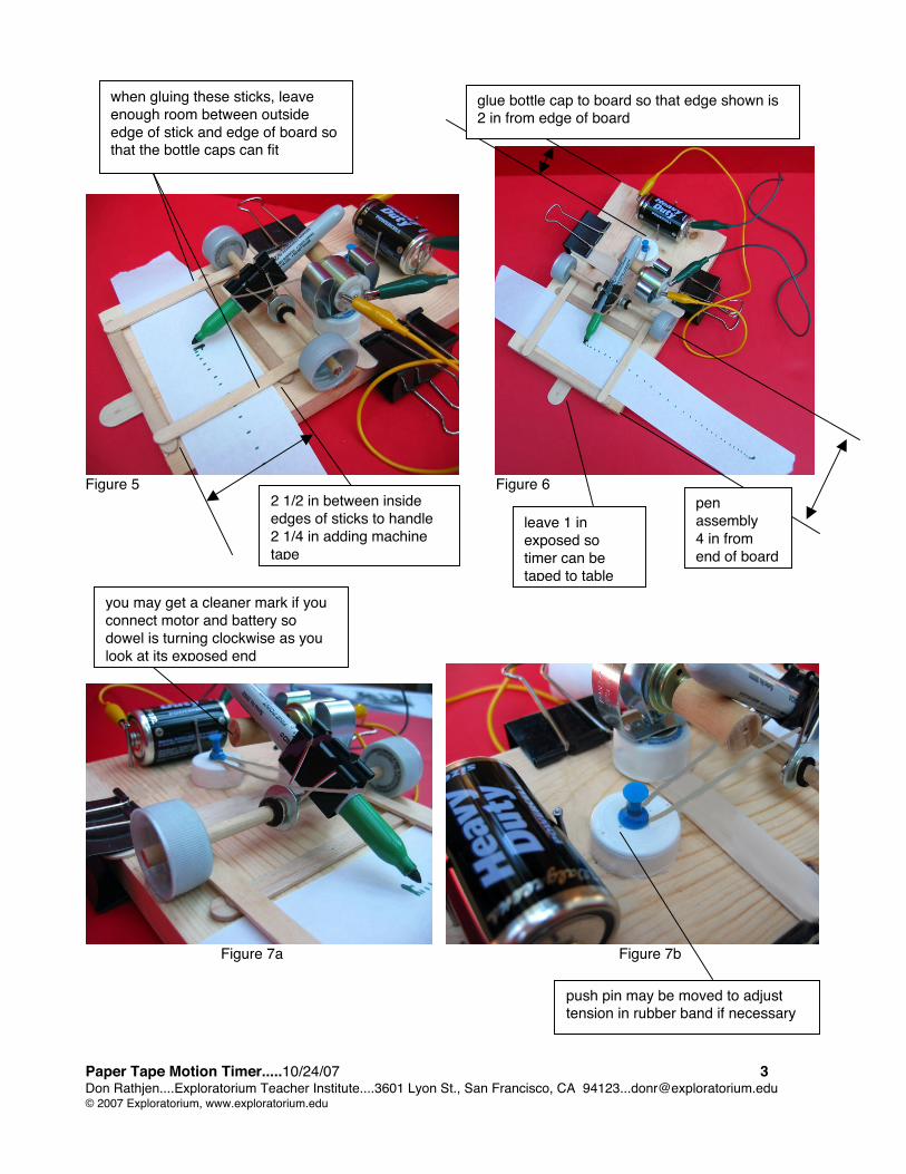
2 1/2 in between insideedges of sticks to handle2 1/4 in adding machinetape
penassembly4 in fromend of board
when gluing these sticks, leaveenough room between outsideedge of stick and edge of board sothat the bottle caps can fit
push pin may be moved to adjusttension in rubber band if necessary
you may get a cleaner mark if youconnect motor and battery sodowel is turning clockwise as youlook at its exposed end
glue bottle cap to board so that edge shown is2 in from edge of board
leave 1 inexposed sotimer can betaped to table

Paper Tape Motion Timer.....10/24/07 4Don Rathjen....Exploratorium Teacher Institute....3601 Lyon St., San Francisco, CA [email protected]© 2007 Exploratorium, www.exploratorium.edu
To Do and Notice1. Place a piece of adding machine tape about 3 ft long in the timer. Thread the paper through the craft stickpaper guides.2. Turn on the timer and slowly pull the paper a few inches. Inspect the paper to make sure that the pen ismaking distinct marks on the tape (see an example of a tape in Figures1, 5 and 6). If it doesn’t, adjust theposition of the tongue depressor that has the motor mount on it, and/or adjust the position of the dowel that hitsthe pen by turning the whole broom holder motor mount assembly.3. Continue to run test tapes and make adjustments until the marks are satisfactory.4. You can now use the timer to make a record of motion which will allow you to do such things as determiningthe displacement, velocity, and acceleration of a toy car and finding the acceleration of a freely falling object(i.e., the value of “g”). Just use masking tape to attach the paper tape to the object whose motion you wish torecord, and let the object pull the tape through the timer.
Motion Graphs for a Spring-Driven Toy CarAttach a paper tape to a spring-driven toy car with masking tape, and make a record of the motion as
the car accelerates and then coasts to a stop. A reduced copy of an actual tape is shown in Figure 8 (theoriginal tape has only the the dots -- the vertical lines and numbers are added as discussed in the followingparagraph).
Mark the start of the tape. Use an arbitrary time interval -- e.g., 3 "ticks" (a "tick" will be a single intervalor space between successive marks on the tape) -- and mark the tape at these 3-tick intervals. Each 3-spacesection represents a velocity -- a distance which you can measure in cm, and a time of 3 "ticks." Forconvenience, we'll call each 3-tick interval a "tock." Each tock represents an equal amount of time. It's a goodidea to number each tock, as shown.
Figure 8
Cut the tape at each dividing mark, andplace each section vertically, with one end alonga horizontal base line. Place each successivestrip to the right of the one preceding it. SeeFigure 9.
What you have made is agraph of velocity (vertical axis; units of cm/"tock")vs. time (horizontal axis; units of "tocks"). As thecar accelerates, each successive section of tapegets taller, and as it slows down, each successivesection gets shorter. At constant speed, thesections are the same height.
Figure 9
The sections that follow will show how to construct displacement and acceleration graphs, usinginformation from the velocity graph.
Paper Tape Motion Timer.....10/24/07 5Don Rathjen....Exploratorium Teacher Institute....3601 Lyon St., San Francisco, CA [email protected]© 2007 Exploratorium, www.exploratorium.edu
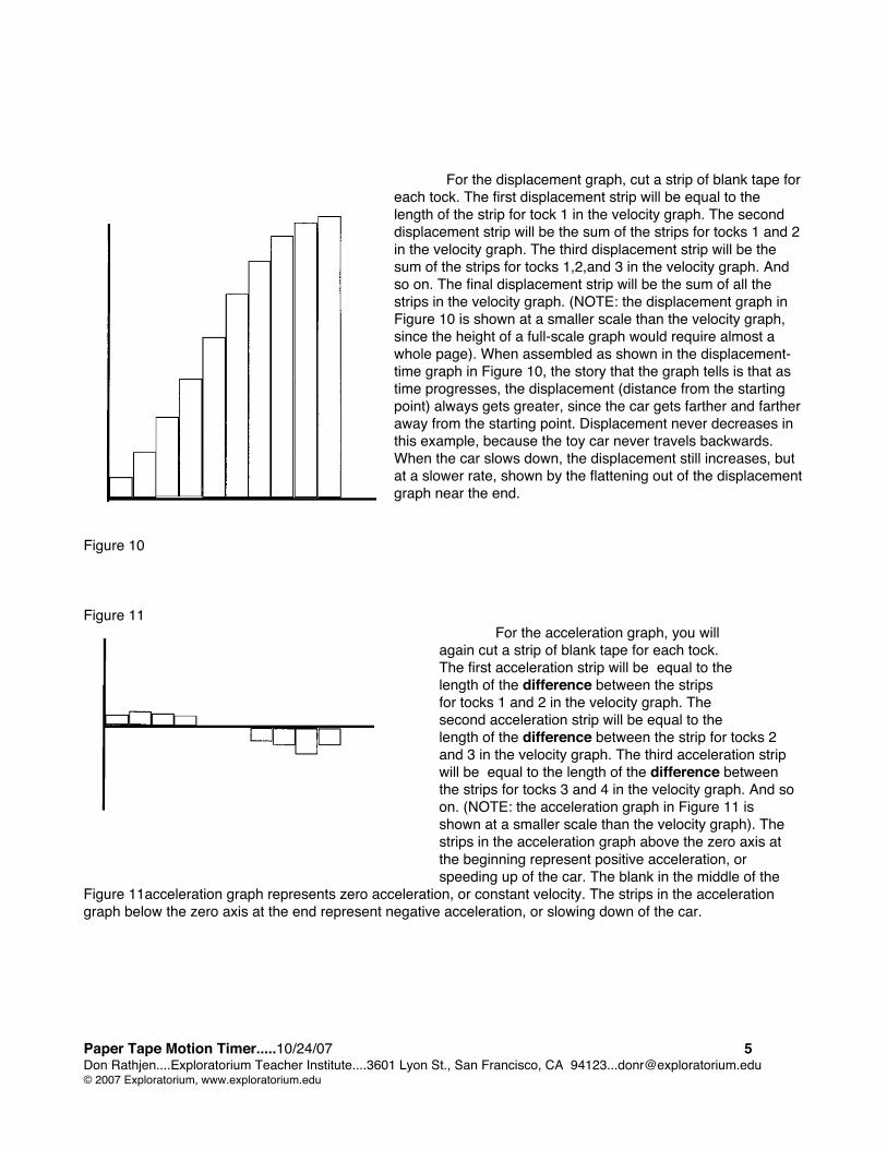
For the displacement graph, cut a strip of blank tape foreach tock. The first displacement strip will be equal to thelength of the strip for tock 1 in the velocity graph. The seconddisplacement strip will be the sum of the strips for tocks 1 and 2in the velocity graph. The third displacement strip will be thesum of the strips for tocks 1,2,and 3 in the velocity graph. Andso on. The final displacement strip will be the sum of all thestrips in the velocity graph. (NOTE: the displacement graph inFigure 10 is shown at a smaller scale than the velocity graph,since the height of a full-scale graph would require almost awhole page). When assembled as shown in the displacement-time graph in Figure 10, the story that the graph tells is that astime progresses, the displacement (distance from the startingpoint) always gets greater, since the car gets farther and fartheraway from the starting point. Displacement never decreases inthis example, because the toy car never travels backwards.When the car slows down, the displacement still increases, butat a slower rate, shown by the flattening out of the displacementgraph near the end.
Figure 10
Figure 11 For the acceleration graph, you willagain cut a strip of blank tape for each tock.The first acceleration strip will be equal to thelength of the difference between the stripsfor tocks 1 and 2 in the velocity graph. Thesecond acceleration strip will be equal to thelength of the difference between the strip for tocks 2and 3 in the velocity graph. The third acceleration stripwill be equal to the length of the difference betweenthe strips for tocks 3 and 4 in the velocity graph. And soon. (NOTE: the acceleration graph in Figure 11 isshown at a smaller scale than the velocity graph). Thestrips in the acceleration graph above the zero axis atthe beginning represent positive acceleration, orspeeding up of the car. The blank in the middle of the
Figure 11acceleration graph represents zero acceleration, or constant velocity. The strips in the accelerationgraph below the zero axis at the end represent negative acceleration, or slowing down of the car.

Paper Tape Motion Timer.....10/24/07 6Don Rathjen....Exploratorium Teacher Institute....3601 Lyon St., San Francisco, CA [email protected]© 2007 Exploratorium, www.exploratorium.edu
Timer CalibrationTurn the timer on, letting it run for a few seconds without pulling the tape so that a mark will be made at
the beginning. Then pull the tape slowly through the timer for 5 seconds (as exactly as you can do this).Starting at the beginning of the tape, draw a line through the first mark, and another line after each ten
intervals. Count the number of 10-interval regions and multiply by 10, and then add on any remaining individualintervals. This will give the total number of intervals. (It’s easier to keep track of things this way than by countingall the intervals individually, since there will likely be a large number.)
To find the frequency of the timer -- that is, the number of intervals per second -- divide the totalnumber of intervals by the number of seconds you pulled the tape.
To find the period of the timer – that is, the time for one interval, or seconds per interval -- divide 5seconds by the total number of intervals.NOTE: Remember that the time between marks is always the same, since the motor runs at constant speed.If the marks are farther apart, the larger distance just means that the tape was being pulled faster; if the marksare closer together, the smaller distance means that the tape was being pulled slower. The distance betweenmarks may vary, but the time is constant.
Finding the Value of "g"Use masking tape to attach a paper tape to a reasonably heavy object, such as a C or D battery (a very
light object will be more subject to error due to friction of the tape passing through the timer). The drop shouldbe at least the height of a normal table, and may be higher if you can conveniently find a longer drop. Make thepaper tape the length of the entire drop. If feasible, you might consider tilting the timer on its side to minimizefriction of the tape passing through the guides..
Start the timer and let the object drop, generating a record of motion on the tape.If the distance of the drop is short (i.e., table height), use a single tick as your time unit. If the drop is
considerably longer, giving many marks on the tape, use a larger time unit, such as 3 ticks = 1 tock. Measurethe distance in cm for each time unit (tick or tock). As in the earlier procedure for making a velocity-time graph,the distance you measure for each tock represents a velocity, in cm/tick, or cm/tock.
Make a velocity-time graph using your data.Find the slope of the velocity-time graph in cm/tick/tick (cm/tick2) or cm/tock/tock (cm/tock2). This slope
represents the acceleration of the falling object.Use your calibration results to perform a unit analysis conversion of the slope value from cm/tick2 or
cm/tock2 to m/s2. An example of such a conversion is shown below (the values used for frequency and slope arerepresentative of actual data obtained with tape timers).
Calibration of timer (frequency) = 24 ticks/s
Slope of graph = 1.3 cm/tick2
1.2 cm x 1 m x 26 ticks x 26 tick = 8.1 m tick2 100 cm 1 s 1 s s2
While there is a notable error between the experimental value of 8.1 m/ s2, and the accepted value of9.8 m/s2, the timer nevertheless illustrates the process quite elegantly, considering its simplicity, obviouspotential sources of error and low cost. On occasion, values have been obtained that are quite close to theactual value.
CreditThis timer draws its inspiration from the PSSC Physics ticker tape timers of the 50's and 60's.

Paper Tape Motion Timer.....10/24/07 7Don Rathjen....Exploratorium Teacher Institute....3601 Lyon St., San Francisco, CA [email protected]© 2007 Exploratorium, www.exploratorium.edu
SOME TIPS, NOTES, COMMENTS AND HELPFUL HINTSFOR THE PAPER TAPE TIMER
• Take the cap off the Sharpie before turning the timer on!
• Put the cap back on the Sharpie when finished, or if you are going to be more than a fewminutes between runs! If you leave the Sharpie uncapped for a prolonged period it will dryout!
• The timer seems to operate better and make cleaner marks if you connect the motor andbattery so the dowel is turning clockwise as you look at its exposed end.
• There are four ways to adjust the position of the motor-dowel assembly so that the Sharpievibrates in the proper way. Use any or all as necessary:
1) adjust the position of the tongue depressor (or stack of tongue depressors if yourtimer has more than one) that has the motor mount on it by loosening the pressure on the twolarge binder clips and moving the tongue depressor
2) slide the pen forward or backward a little in the binder clip (the pen is held firmly;carefully twist and slide the pen to move it)
3) adjust the position of the dowel that hits the pen by rotating the broom holder-motorassembly
4) occasionally, small differences in the brands of the grip-clip broom holders used formotor mounts may require the use of a few additional tongue-depressor craft sticks as shimsunder the one to which the motor mount is glued -- this will raise the height of the motorassembly so the dowel will hit the pen -- the additional sticks don't need to be glued, but justinserted under the one with the motor mount
• The function of the tongue depressor that is glued to the bottom of the base and protrudesout about an inch is to allow the timer to be taped down. The bottom handles of the two largebinder clips can also be used for this purpose. If you don't tape the timer down, it may movearound or wobble while it's working, and results may suffer.
• Occasionally the dowel may work itself off the motor shaft after considerable usage. If so,just replace it (push it on the motor shaft as far as possible without hitting the motor casing).There is likely an alternate hole drilled in the opposite end, so if necessary, reverse the endsof the dowel and use the new hole.
• A 1/16 in. hole is slightly too small and a 5/64 hole slightly too big for the hole in the dowel.It's very hard to get the motor shaft in the smaller hole, and the larger hole may allow someslipping of the shaft in the hole after a time. A #50 Wire Gauge drill (1.78 mm) works very well-- it's between the two common sizes just noted. It's not a common size, but you can probablyfind it if you make an effort to look for it.