Embed Size (px)
Citation preview
650 IEEE JOURNAL OF QUANTUM ELECTRONICS, VOL. QE-14, NO. 9, SEPTEMBER 1978
Papers
Phase Conjugate Optics and Real-Time Holography
AMNON YARIV, FELLOW, IEEE
(Invited Paper)
Abstract-Nonlinear optical mixing can be used to perform a variety of new optical functions, as well as real-time holography. The theory and some of the first experiments are described.
I. INTRODUCTION
P HASE conjugate optics (PCO) is the name which seems to attach itself to a new and exciting area in coherent optics.
This area involves the use of nonlinear optical techniques for real-time processing of electromagnetic fields. The name, phase conjugate optics, is due to the fact that all the applica- tions demonstrated or proposed to date involve phase reversal of an incoming electromagnetic wave.
The field is still young enough so that a brief recounting of the main developments is possible. The first milestone was the demonstration by Zeldovich, Nosach, and collaborators [ l ] , [2] of the cancellation of propagation distortion by stimulated Brillouin scattering. The author, independently, proposed [3], [4] and analyzed the use of three-wave mixing in crystals for overcoming image “loss” by modal phase dis- persion in multimode fibers and for real-time holography. Hellwarth suggested [5] four-wave mixing as an attractive process for phase conjugation, and showed that it overcomes some serious phase matching problems inherent in three-wave processes. Yariv and Pepper [6] showed that the four-wave process for phase conjugation was also capable of amplifying an incoming wave, as well as rendering its complex conjugate version and, in the limit of sufficient pumping, of mirrorless oscillation.
The first observations of phase conjugation by four-wave mixing were reported by Jensen and Hellwarth [7] and by Bloom and Bjorklund [SI, both parties using CSz as the non- linear medium, Parametric amplification and oscillation in four-wave mixing was reported by Bloom, Liao, and Economou [9] and by Pepper, Fekete, and Yariv [ l o ] . Phase conjugation by three-wave mixing in crystals was demonstrated by Avizonis et al. [ 111 . Wang and Guiliano [ 121 demonstrated the ability
Manuscript received May 3, 1978. This work was supported by the Army Research Office, Durham, NC.
The author is with the Departments of Applied Physics and Electrical Engineering, California Institute of Technology, Pasadena, CA 91125.
of the stimulated Brillouin process to restore high spatial fre- quencies. Optical phase conjugation and image restoration by stimulated Raman scattering was demonstrated by Zeldovich and collaborators [13] .
11. PHASE CONJUGATION AS “TLME REVERSAL” Before embarking on a detailed discussion of the means for
obtaining complex conjugates of electromagnetic fields, it may be useful to describe the properties of such fields. We will do so in two different instances: (A) propagation through a dis- torting medium; and (B) image transmission in a fiber.
A. Propagation through a Distorting Medium Consider as an example the problem of an optical beam
El (?, t ) = Re [I)(?) exp i ( a t - kz)]
= Re [A (;) eiwt] (1)
propagating through a linear lossless distorting medium es- sentially in the z direction (from left to right). The depen- dence of $ on ? reflects spatial modulation by information, the effects of distortion, and diffraction. If in some region of space near zo we somehow generate a field Ez(?, t ) which, locally, is described by
E2 (Y), t ) = Re [ $*(?) exp i ( a t + kz)]
= Re [A2 (;) eiw ‘1 (2)
then
A2(r‘)=Af(?)forallz<zo.
The field E2(?, t ) will be called in this paper the complex conjugate of E1 (?, t). We note that to get Ez from E1 we take the complex conjugate of the spatial part only, leaving the factor exp ( ia t ) intact. (This is equivalent to leaving the spatial part alone but reversing the sign o f t . That is, the field E2 is related to E1 by “time reversal.”)
To appreciate the practical consequences of conjugation, consider a field El propagating from left to right through a distorting medium, This causes the wave to “lose” whatever
0018-9197/78/0900-0650$00.75 01978 IEEE
YARIV: PHASE CONJUGATE OPTICS AND REAL-TIME HOLOGRAPHY 6 5 1
information it may carry as spatial modulation or to acquire some undesirable spatial properties. If the complex conjugate field Ez is generated, it will traverse the distorting medium in the reverse direction and reemerge with the original unspoiled properties of the beam E l .
The above statements can be verified by considering the propagation of an optical beam
El (?, t ) = Re [I)(?) exp i(wt - kz)] (3)
propagating from left to right through an “atmosphere” whose dielectric constant, assumed stationary over the time needed for a round trip, is E(?). (The medium is assumed lossless, so ~ ( r ) is real.)
The (scalar) wave equation is taken as
V 2 E t w2pe(?) E = 0,
which, using (3) becomes a I ) az
V2 J/ t [02pe (? ) - k 2 ] $ - 2ik - = 0.
The complex conjugate of the last equation
Vz I)* t [ w 2 p e ( ? ) - k2] I)* t 2ik-= 0 a \L* az (4)
can be viewed formally as the wave equation describing the propagation of
Ez (?, t ) = Re [ J/*(?) exp i ( o t + kz)]
which is a wave propagating in the ( - z ) direction, i.e., op- positely to E1 (?, t) and having at each point a complex ampli- tude equal to the complex conjugate of El. This one-to-one correspondence between the two waves is the reason for the unraveling of the degradation effects (equivalent to time re- versal) in the propagation of the conjugate beam.
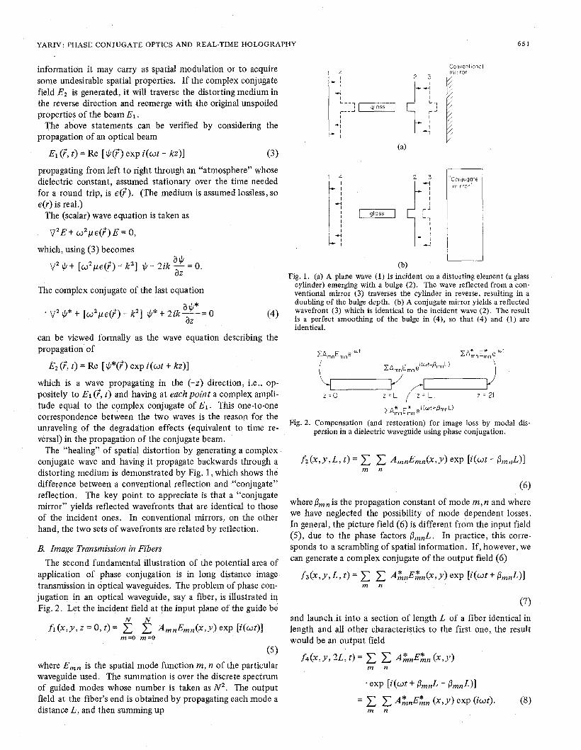
The “healing” of spatial distortion by generating a complex conjugate wave and having it propagate backwards through a distorting medium is demonstrated by Fig. 1, which shows the difference between a conventional reflection and “conjugate” reflection. The key point to appreciate is that a “conjugate mirror” yields reflected wavefronts that are identical to those of the incident ones. In conventional mirrors, on the other hand, the two sets of wavefronts are related by reflection.
B. Image Transmission in Fibers The second fundamental illustration of the potential area of
application of phase conjugation is in long distance image transmission in optical waveguides. The problem of phase con- jugation in an optical waveguide, say a fiber, is illustrated in Fig. 2. Let the incident field at the input plane of the guide be
N N f l ( x , ~ , z = O , t ) = AmnEmn(x,Y)exp [ i ( ~ t ) l
m=O m=O
(5 1 where Emn is the spatial mode function m, n of the particular waveguide used. The summation is over the discrete spectrum of guided modes whose number is taken as N2. The output field at the fiber’s end is obtained by propagating each mode a distance L, and then summing up
4 I
c ,
Conventlonal rn l r ror
t--i
1 ‘‘Conpg?,:e
mirror
I (b)
Fig. 1. (a) A plane wave (1) is incident on a distorting element (a glass cylinder) emerging with a bulge (2). The wave reflected from a con- ventional mirror (3) traverses the cylinder in reverse, resulting in a doubling of the bulge depth. (b) A conjugate mirror yields a reflected wavefront (3) which is identical to the incident wave (2). The result is a perfect smoothing of the bulge in (4), so that (4) and (1) are identical.
CAmnEmne’Wt CA:nEGne’Wt
2 = o 2 = 2L
ZA* E* ei(wt+&,nL) mn mn
Fig. 2. Compensation (and restoration) for image loss by modal dis- persion in a dielectric waveguide using phase conjugation.
where Pmn is the propagation constant of mode m, n and where we have neglected the possibility of mode dependent losses. In general, the picture field (6) is different from the input field ( 9 , due to the phase factors PrnnL. In practice, this corre- sponds to a scrambling of spatial information. If, however, we can generate a complex conjugate of the output field (6)
(7) and launch it into a section of length L of a fiber identical in length and all other characteristics to the first one, the result would be an output field
f 4 ( x , ~ , 2L, z) = AZnEZn (x,Y) m n
~ X P [i(ot+ PmnL - PmnLIl
652 IEEE JOURNAL OF QUANTUM ELECTRONICS, VOL. QE-14, NO. 9, SEPTEMBER 1 9 7 8
Except for the complex conjugation, the field at z = 2L,f4 is the same as the input field fl and the spatial information carried by the wave has thus been recovered.
Next we will discuss the basic approaches proposed to date for phase conjugation.
111. WAVE CONJUGATION BY THREE-WAVE MIXING Three-wave mixing of optical waves takes place in crystals
lacking inversion symmetry [ 141 . If two fields
E , = + A l exp i ( o t - k W z ) t C.C.
and (9)
E2 = *Az exp i(2wt - k2wz) t C.C.
are incident on such a crystal, then a polarization will be set in the crystal in the form of
P t Z ] = 3dA2 exp i (2o t - k2 ” z )
. [El exp i ( o t - k w z ) ] * t C.C.
= 3dA2A7 exp i [ut - ( k Z w - k W ) z ] t C.C. (10)
If k Z w = 2kW, the polarization P(NL) will radiate a wave
E 3 a dA2AT exp i(wt - kWz) (1 1)
which, upon conventional reflection from a plane mirror, becomes
(E3)refl a dA2A? exp i (wt t kWz) (12)
and is thus the complex conjugate of the original field E l . The use of three-wave mixing plus conventional reflection
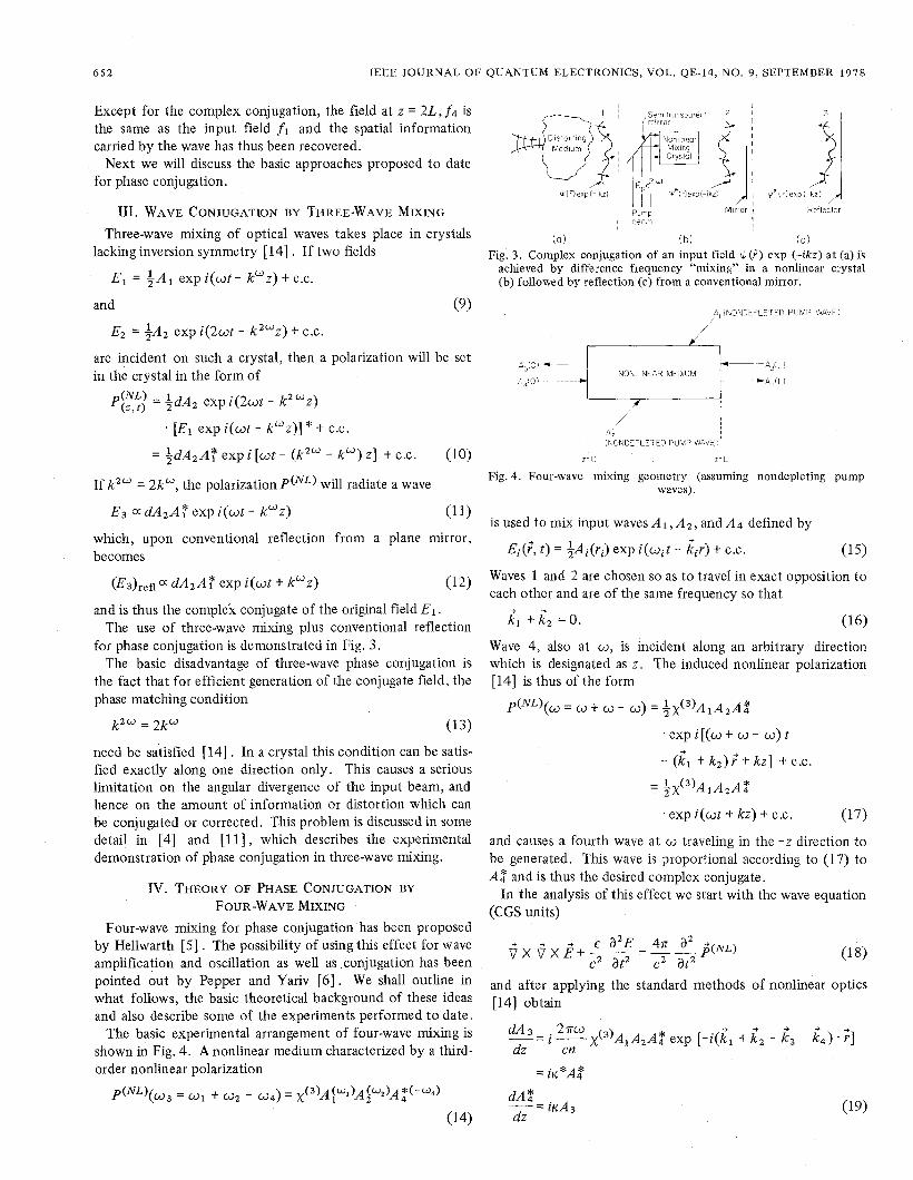
for phase conjugation is demonstrated in Fig. 3 , The basic disadvantage of three-wave phase conjugation is
the fact that for efficient generation of the conjugate field, the phase matching condition
k2w = 2kW (13)
need be satisfied [14] . In a crystal this condition can be satis- fied exactly along one direction only. This causes a serious limitation on the angular divergence of the input beam, and hence on the amount of information or distortion which can be conjugated or corrected. This problem is discussed in some detail in [4] and [ l l ] , which describes the experimental demonstration of phase conjugation in three-wave mixing.
Iv. THEORY OF PHASE CONJUGATION BY
FOUR-WAVE MIXING Four-wave mixing for phase conjugation has been proposed
by Hellwarth [ 5 ] . The possibility of using this effect for wave amplification and oscillation as well as conjugation has been pointed out by Pepper and Yariv [ 6 ] . We shall outline in what follows, the basic theoretical background of these ideas and also describe some of the experiments performed to date.
The basic experimental arrangement of four-wave mixing is shown in Fig. 4. A nonlinear medium characterized by a third- order nonlinear polarization
P ( N L ) ( u 3 = m1 t m2 - w 4 ) = x ( ~ ) A ~ ~ * ) A ~ ~ * ) A ~ ( - ~ ~ )
(14)
~ Pump Mirror 1 Refleclsr , 3 e o 7 1
(a! !
( b i i c ) Fig. 3. Complex conjugation of an input field $(?) exp (-ikz) at (a) is
achieved by difference frequency “mixing” in a nonlinear crystal (b) followed by reflection (c) from a conventional mirror.
L I
Fig. 4. Four-wave mixing geometry (assuming nondepleting pump waves).
is used to mix input waves A I , A2, and A4 defined by
E~(?, t ) = & A ~ ( ~ J exp i ( w j t - rtjr) t c.c. (15)
Waves 1 and 2 are chosen so as to travel in exact opposition to each other and are of the same frequency so that
rt, ti, = o . (16)
Wave 4, also at m, is incident along an arbitrary direction which is designated as z . The induced nonlinear polarization [14] is thus of the form
p(NL)(w = w t 0 - 0) = 1 2x ( 3 ) ~ 1 ~ 2 ~ $
. e x p i [ ( u t w - w ) t
- (SI t k2) r‘t kz] t c.c.
= $ x ( ~ ) A ~ A ~ A $
. exp i(wt t kz) t C.C. (17)
and causes a fourth wave at c3 traveling in the - z direction to be generated. This wave is proportional according to (17) to A: and is thus the desired complex conjugate.
In the analysis of t h s effect we start with the wave equation (CGS units)
and after applying the standard methods of nonlinear optics [14] obtain
YARIV: PHASE CONJUGATE OPTICS AND REAL-TIME HOLOGRAPHY 653
where we used the fa$ that t i2 = 0, i 3 t i 4 = 0, took the z direction as that of k4, and used the adiabatic approximation
The complex coupling constant K is given by
If we specify the complex amplitudes A3(L) and A4(0) of the two weak waves at their respective input planes (z = L , z = 0), the solution of (19) is
(21)
In the case of phase conjugation, we have a single input A4(0) at z = 0 and A3(L) = 0. In this case, the reflected wave at the input (z = 0) is
while at the output (z = L ) ,
Equation (22) is our main result. It shows that at z = 0 the reflected field A3(0) is proportional to the complex conjugate of the incident field A4(0) multiplied by a factor -i((K*/l K I ) *
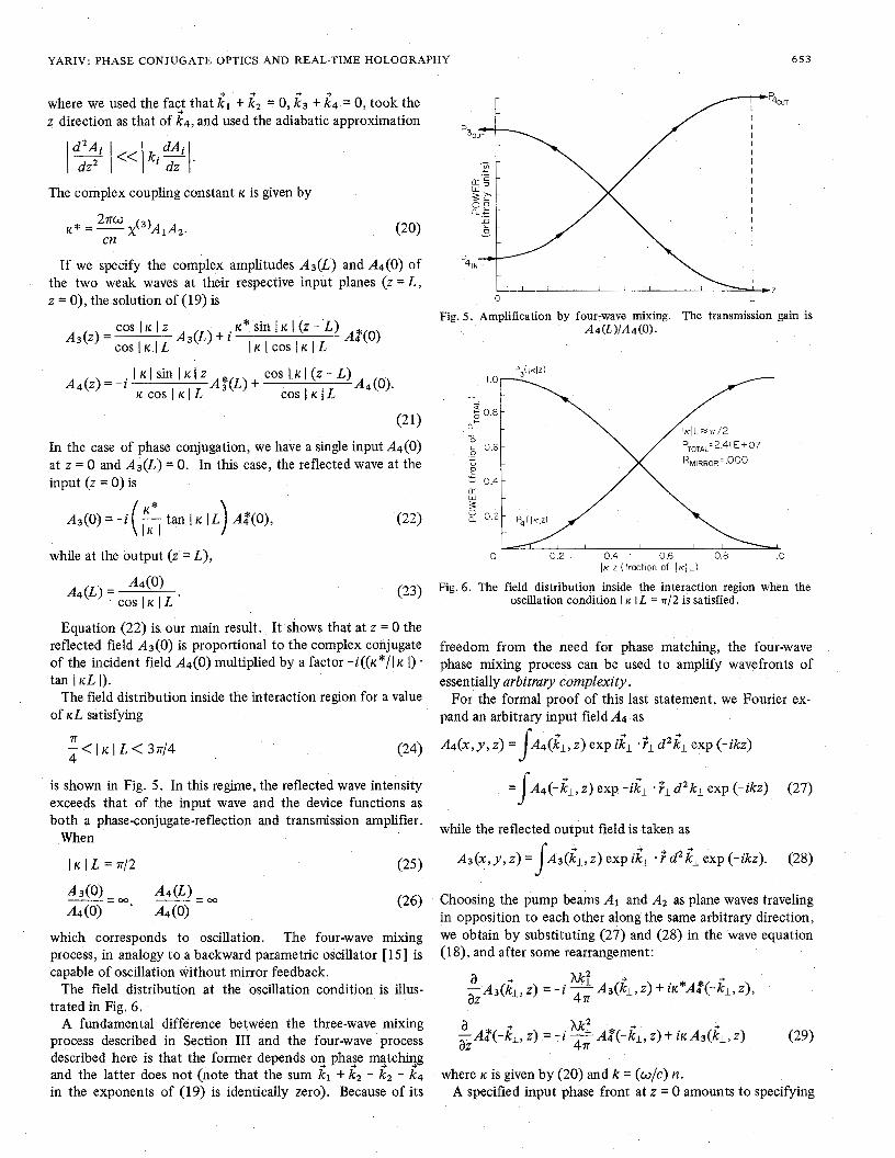
tan I KL I ) . The field distribution inside the interaction region for a value
of KL satisfying
- < I K I L < 3 7 / 4 71
4 (24)
is shown in Fig. 5. In this regime, the reflected wave intensity exceeds that of the input wave and the device functions as both a phase-conjugate-reflection and transmission amplifier.
When
IKIL=-I /2 (25)
which corresponds to oscillation. The four-wave mixing process, in analogy to a backward parametric oscillator [ 151 is capable of oscillation without mirror feedback.
The field distribution at the oscillation condition is illus- trated in Fig. 6.
A fundamental difference between the three-wave mixing process described in Section I11 and the four-wave process described here is that the former depends 02 phase ma+tchi2g and the latter does not (note that the sum kl t k2 - k2 - k4 in the exponents of (19) is identically zero). Because of its
0 L
Fig. 5. Amplification by four-wave mixing. The transmission gain is -h(L)/A4(0).
a L
5 0.6-
0 - L
u -
0.4 - LT w - z :: 0.2 -
/-
0 0.2 0.4 0.6 0.8 I .0 I K I Z (fraction of I K / L )
Fig. 6 . The field distribution inside the interaction region when the oscillation condition I K IL = n/2 is satisfied.
freedom from the need for phase matching, the four-wave phase mixing process can be used to amplify wavefronts of essentially arbitrary complexity.
For the formal proof of this last statement, we Fourier ex- pand an arbitrary input field A4 as
~ ~ ( x , y , z) = A4(k1, z) exp dl d 2 i ~ exp (-ikz) I + =J A4(-iL,z) exp -iil .Fld2kl exp.(-ikz) (27)
while the reflected output field is taken as
A3(x ,y ,z )= &( i l ,Z)expi i l . id2 i lexp(- ikz) . (28) J Choosing the pump beams AI and A2 as plane waves traveling in opposition to each other along the same arbitrary direction, we obtain by substituting (27) and (28) in the wave equation (18), and after some rearrangement:
where K is given by (20) and k = (w/c) n. A specified input phase front at z = 0 amounts to specifying
654 IEEE JOURNAL OF QUANTUM ELECTRONICS, VOL. QE-14, NO. 9, SEPTEMBER 1978
A2(-iL, 0). SincePo mixing takes place at z > L , we take the reflected field A3(kL,L) to be zero at the output z = L . With these boundary conditions, the solution to (29) is
At the input to the nonlinear medium, z = 0, we thus have
which shows that the individual plane wave components of the arbitrary waivefronts behave as in the plane wave case ex- cept that each kl component of the output beam A 3 couples directly to the -kl component of the input wave A4. It is now a straightforward, though formal, procedure to show, using the uniqueness property of linear parabolic differential equa- tions, that the relation (31) in conjunction with (19) and (28) signifies
+
(324
so that an arbitrarily complex incident wavefront A4 gives rise at z < 0 to a reflected and amplified field A3, which is everywhere the complex conjugate of A4.
We have shown above that oscillation results when I K I L = 7r/2. This condition is most likely to be satisfied when the waves A3 and A4 are parallel to the input waves A1 and A,, since this is the direction of maximum beam overlap. This, however, is often the direction of least interest, since the “output” waves A3 and A4 will be degenerate in their directions, as well as their frequencies, with the “pump” waves A1 and A 2 .
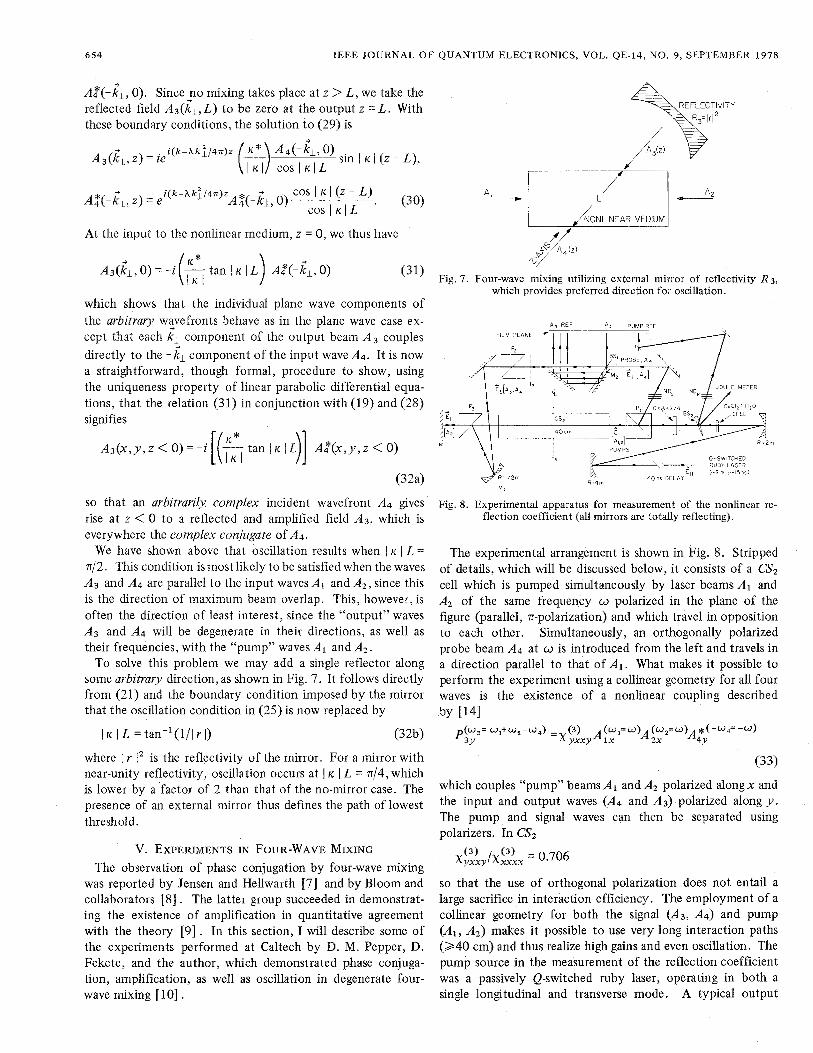
To solve this problem we may add a single reflector along some arbitrary direction, as shown in Fig. 7. It follows directly from (21) and the boundary condition imposed by the mirror that the oscillation condition in (25) is now replaced by
I K I L = tan-’(l/I r I ) (32b)
where j r 1, is the reflectivity of the mirror. For a mirror with near-unity reflectivity, oscillation occurs at I K I L = 4 4 , which is lower by a factor of 2 than that of the no-mirror case. The presence of an external mirror thus defines the path of lowest threshold.
v. EXPERIMENTS IN FOUR-WAVE MIXING The observation of phase conjugation by four-wave mixing
was reported by Jensen and Hellwarth [7] and by Bloom and collaborators [SI . The latter group succeeded in demonstrat- ing the existence of amplification in quantitative agreement with the theory [9] . In this section, I will describe some of the experiments performed at Caltech by D. M. Pepper, D. Fekete, and the author, which demonstrated phase conjuga- tion, amplification, as well as oscillation in degenerate four- wave mixing [ 101 .
Fig. 7. Four-wave mixing utilizing external mirror of reflectivity R3, which provides preferred direction for oscillation.
MFTEfi
““3
Fig. 8. Experimental apparatus for measurement of the nonlinear re- flection coefficient (all mirrors are totally reflecting).
The experimental arrangement is shown in Fig. 8. Stripped of details, which will be discussed below, it consists of a CS2 cell which is pumped simultaneously by laser beams A1 and A2 of the same frequency o polarized in the plane of the figure (parallel, n-polarization) and which travel in opposition to each other. Simultaneously, an orthogonally polarized probe beam A4 at o is introduced from the left and travels in a direction parallel to that of A x . What makes it possible to perform the experiment using a collinear geometry for all four waves is the existence of a nonlinear coupling described by t141
p(w3=wI+Wz-w4) 3Y = (3) A(w’=w) (w*=w) *(-w,=-w) Xyxx , 1x A 2x A4Y
(33)
which couples “pump” beams A1 and A2 polarized along x and the input and output waves (A4 and A3) polarized along y . The pump and signal waves can then be separated using polarizers. In CS2
x ~ ~ y / x ~ ~ x = 0.706
so that the use of orthogonal polarization does not entail a large sacrifice in interaction efficiency. The employment of a collinear geometry for both the signal (A3, A4) and pump (Ax, A,) makes it possible to use very long interaction paths (240 cm) and thus realize high gains and even oscillation. The pump source in the measurement of the reflection coefficient was a passively Q-switched ruby laser, operating in both a single longitudinal and transverse mode. A typical output
YARIV: PHASE CONJUGATE OPTICS AND REAL-TIME HOLOGRAF
pulse energy was 7 to 13 mJ with a duration of 15 ns. The typical intensity spot size was determined to be 2.2 mm in diameter. The output beam was reflected by a 2 : 1 spherical mirror collimator and folded to yield an optical path delay of 40 ns before entering the interaction region. Thus, return sig- nals were prevented from reaching the laser throughout the duration of the pulse. A 1 cm thick cell containing varying concentrations of CuClz in HzO was used to attenuate the laser beam for various input energies. The beam passed next through a calcite Glan laser prism (PI), and then into the CSz medium, which was contained in a 40 cm long, 2 cm diameter glass cell. Mirror Ml retroreflected the pump beam, giving rise to a counterpropagating component Az. The cell was tilted off axis to prevent Fresnel reflections from interfering with mea- sured fields. Prism PI served a dual function: it passed the pump beam ( A I ) .rr-polarized into the interaction medium, and in addition coupled an “s” polarized probe A4 pulse of order
that of the pump energy (energy determined by the orientation of wave plate $). This probe was then beam-split and passed through a calibrated beam splitter-mirror system (BS1, M z ) providing a sequence of reflected beams, each being reduced in intensity by a factor of two which were incident upon the film plane. For comparison, a Fresnel reflected (via BSz) pump beam was also recorded. Both of these beams were attenuated through neutral density stacks (NDs and NDR) prior to impinging on the film plane. The laser energy was monitored by a calibrated Fresnel reflection (off BS2) using a pyroelectric detector and a digital readout.
The forward-going probe beam A4, now propagated through prism Pz , oriented to pass this s polarized field, thus serving to eliminate any scattered or Fresnel reflected n-polarized fields from creating systematics, was then coupled back into the CSz cell through a spherical mirror M3 and another Glan laser prism P3 (oriented similar to that of PI) between the cell and Ml. Thus, prisms P1 and P3 constrained the probe beam to interact only in the CSz cell. The purpose ofM3 was to focus and confine the probe to propagate within the pump beam volume.
The phase conjugate nature of the reflected wave, i.e., A3(0) aA4*(0), was established through the use of the mirror M3 (see Fig. 8). This mirror focuses the collimated input probe beam A4 on the midplane f3. A phase conjugate reflection AB, being a “time-reversed’’ replica of the input wave Aq, should emerge from the CSz cell with virtual emanation from the focal spot at f 3 and thus be collimated. That this was the case was established using the beam spot photographs (taken by re- flectingA3 off BS1) in the film plane.
The presence of mirror M3 insures that only reflected phase conjugated radiation is collimated in the film plane. The presence of unwanted s-polarized radiation due to residual birefringence in the optical components, imperfect extinction in the polarizers, and to ellipse rotation in CSz, gave rise to a divergent output and did not affect the measurement of the reflection coefficient materially.
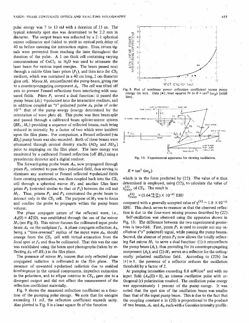
Fig. 9 shows the measured reflection coefficient as a func- tion of the pumping pulse energy. We note that for energies exceeding 11 mJ, the reflection coefficient exceeds unity. Also plotted in Fig. 9 is a least square fit of the function
’HY 655
W K
i
INPUT ENERGY (mJ!
Fig. 9. Plot of nonlinear power reflection coefficient versus pump energy (in mJ). Data [ e ] ; least squares fit to R = tanZ (arep) [solid line].
FILM P L A V E - 3
TO SCOPE, FABRY-PEROT -
R - 4 m
Fig. 10. Experimental apparatus for viewing oscillation.
R = tanZ (&ep)
which is in the form predicted by (22). The value of CY thus determined is employed, using (22), to calculate the value of
XYXXY (3) of CSz. The result is
XYXXY (3) = (1.64:;:::) X ESU compared with a generally accepted value of x(3) - 1.8 X 10-l’ MU. This check serves to reassure us that the observed reflec- tion is due to the four-wave mixing process described by (22).
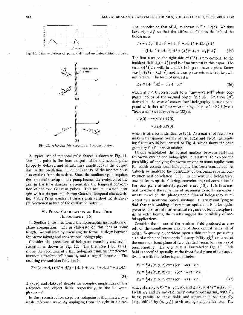
Self-oscillation was observed using the apparatus shown in Fig. 10. The difference between the two experimental geome- tries is two-fold; First, prism PI is used to couple out any os- cillation (“s” polarized) signal, while passing the pump beams. Second, the absence of prism P3 now allows the totally reflect- ing flat mirror Ml to serve a dual function: (1) it retroreflects the pump beam ( A I ) , thus providing for its counterpropagating component (A2); and (2) M I serves as a reflector for the orthog- onally polarized oscillation field. According to (32b) for I r I 1, the presence of a reflector reduces the oscillation threshold by a factor of 2 .
At pumping intensities exceeding 8.8 mW/cmz and with no input field (A4(0) = 0), an intense oscillation pulse with or- thogonal (s) polarization resulted. The oscillation pulse energy was approximately 1 percent of the pump energy. It was noted that the spot size of the oscillation beam was smaller than that of the input pump beam. This is due to the fact that the coupling constant K. in (20) is proportional to the product of two beams, AI and& , each with a Gaussian intensity profile.
656 IEEE JOURNAL OF QUANTUM ELECTRONICS, VOL. QE-14, NO. 9, SEPTEMBER 1978
20 ns/dlv
Fig. 11. Time evolution of pump (left) and oscillator (right) outputs.
f
(b) Fig. 12. A holographic exposure and reconstruction.
A typical set of temporal pulse shapes is shown in Fig. 11. The first pulse is the laser output, while the second pulse (properly delayed and of arbitrary amplitude) is the output due to the oscillation. The nonlinearity of the interaction is also evident from these data. Since the nonlinear gain requires the temporal overlap of the pump beams, the evolution of the gain in the time domain is essentially the temporal convolu- tion of the two Gaussian pulses. This results in a nonlinear gain with a sharper and shorter Gaussian temporal characteris- tic. Fabry-Perot spectra of these signals verified the degener- ate frequency nature of the oscillation output.
m. PHASE CONJUGATION AS REAL-TIME HOLOGRAPHY [ 161
In Section I, we mentioned the holographic implications of phase conjugation. Let us elaborate on this idea at some length. We will start by discussing the formal analogy between four-wave mixing and conventional holography.
Consider the procedure of hologram recording and recon- struction as shown in Fig. 12. The first step [Fig. 12(a)] shows the recording of a thin hologram using an interference between a “reference” beam A1 and a “signal” beam&. The resulting transmission function is
T a (A4 + A1) (A: t A?) = IA4 l 2 t I A ~ l 2 t A4AT t
(34)
Al(x,y) and A4(x,y) denote the complex amplitudes of the reference and object fields, respectively, in the hologram plane z = 0.
In the reconstruction step, the hologram is illuminated by a single reference wave A2 impinging from the right in a direc-
tion opposite to that of A1 as shown in Fig. 12(b). We thus have A2 = A ? so that the diffracted field to the left of the hologram is
A3 =TA2a(IA4I2 IA1 I 2 +A4A::+AZAl)Af
= (/A4 1’ + IAl I2)A: -I- A4 t l2 A;. (35)
The first term on the right side of (35) is proportional to the incident field Az(=A: ) and is of no interest in this paper. The term (A:l2A4 Fill, in a thick hologram, have a phase factor exp [-i(2k1 - k4) .?I and is thus phase mismatched, i.e., will not radiate. The term of interest is
A3 a IAl I2A8 = lAlA2 [ A ; (36)
which at z < 0 corresponds to a “time-reversed’’ phase con- jugate replica of the original object field A4. Relation (36) derived in the case of conventional holography is to be com- pared with that of four-wave mixing. For 1 KL I << 1 (weak “hologram”) we may rewrite (22) as
A3(0) = -I’(K*L) &(0)
aA1A2AZ(O)
which is of a form identical to (36). As a matter of fact, if we make a transparent overlay of Fig. 12(a) and 12(b), the result- ing figure would be identical to Fig. 4, which shows the basic geometry for four-wave mixing.
Having established the formal analogy between real-time four-wave mixing and holography, it is natural to explore the possibility of applying four-wave mixing to some applications for which conventional holography has been considered. At Caltech we analyzed the possibility of performing spatial con- volution and correlation [ 171 . In conventional holography, one performs spatial filtering, convolution, and correlation in the focal plane of suitably placed lenses [ 181 . It is thus nat- ural to extend the same line of reasoning to nonlinear experi- ments in which the photographic film of holography is re- placed by a nonlinear optical medium. It is very gratifying to find that this wedding of nonlinear optics and Fourier optics preserves the formal mathematical elegance of both disciplines. As an extra bonus, the results suggest the possibility of use- ful applications.
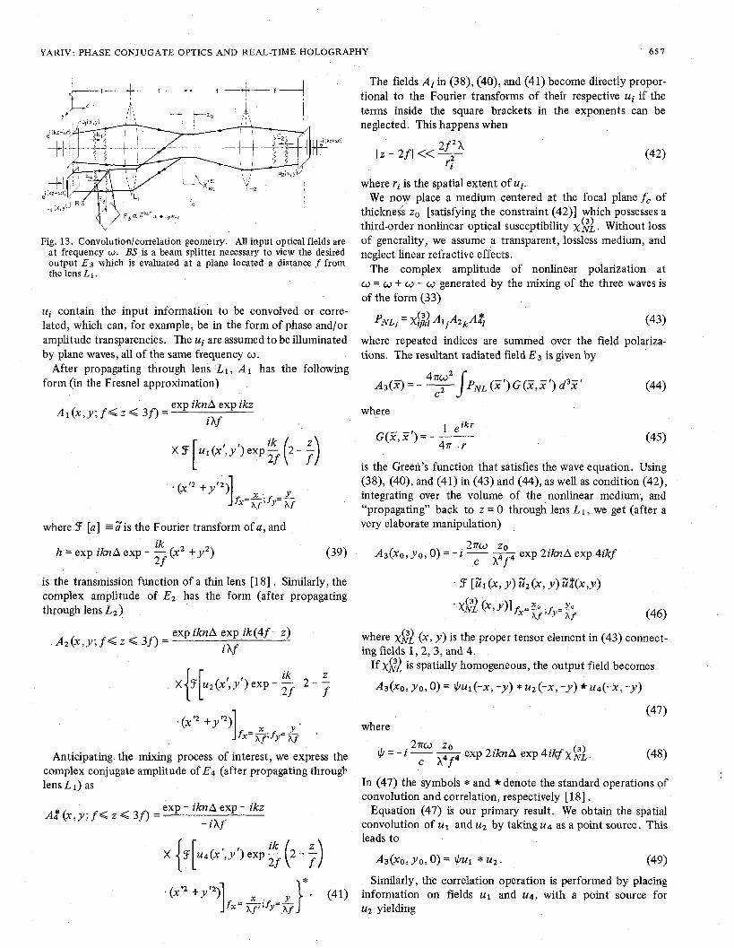
Consider the nature of the resultant field produced as a re- sult of the simultaneous mixing of three optical fields, all of radian frequency w , incident upon a thm medium possessing a third-order nonlinear optical susceptibility ~$2 centered at the common focal plane of two identical lenses (or mirrors) of focal length f . The geometry is illustrated in Fig. 13. Each field is specified spatially at the front focal plane of its respec- tive lens with the following amplitudes:
El = $ A l ( x , y , z ) exp i(kz - at) t c.c.
E2 = $A2(x,y,z) exp -i(kz -t ut) t C.C.
E4 = &A4(x,y, 2 ) exp i(kz - wt) + C.C. (37)
whereA1,4(X,y,0)=u1,4(x,y), andA2(x,y,4f)-u2(x, u). Fields E1 and E2 are essentially counterpropagating, with E4 being parallel to these fields and separated either spatially [e.g., shifted by (x,,ys)] or via orthogonal polarizations. The
YARIV: PHASE CONJUGATE OPTICS AND REAL-TIME HOLOGRAPHY 651
Fig. 13. Convolution/correlation geometry. All input optical fields are a t frequency w . BS is a beam splitter necessary to view the desired output E 3 which is evaluated at a plane located a distance f from the lens L 1 .
ui contain the input information to be convolved or corre- lated, which can, for example, be in the form of phase and/or amplitude transparencies. The ui are assumed to be illuminated by plane waves, all of the same frequency o.
After propagating through lens L1, A 1 has the following form (in the Fresnel approximation)
A 1 ( x , y ; f < z < 3 0 = exp iknA exp ikz
ihf
f =“.f -L x Af’ Y - Af
where 3 [a] ;is the Fourier transform of a, and
h = exp iknA exp - - (x2 + y’) ik 2 f
(39)
is the transmission function of a thin lens [18] . Similarly, the complex amplitude of Ez has the form (after propagating through lens L 2 )
A2(x,y; f < z G 3 f ) = exp ikn A exp ik (4 f - z)
i hf
Anticipating the mixing process of interest, we express the complex conjugate amplitude of E4 (after propagating througk lens L 1) as
A P ( x , y ; f G z < 3f) = exp - iknA exp - ikz
- ihf
The fields Ai in (38)’ (40)’ and (41) become directly propor- tional to the Fourier transforms of their respective ui if the terms inside the square brackets in the exponents can be neglected. This happens when
l z - 2 f l < < - 2 f 2 h r;
where rj is the spatial extent of ui. We now place a medium centered at the focal plane f , of
thickness zo [satisfying the constraint (42)] which possesses a third-order nonlinear optical susceptibility x$L. Without loss of generality, we assume a transparent, lossless medium, and neglect linear refractive effects.
The complex amplitude of nonlinear polarization at o = CJ t w - w generated by the mixing of the three waves is of the form (33)
pNLi = X & ~ 1 ~ ~ 2 ~ 4 (43)
where repeated indices are summed over the field polariza- tions. The resultant radiated field E3 is given by
A 3 ( 3 = - F J ~ N L ( X r ) G (X, X ’) d 3 X r 4nw2
(44)
where 1 e i k r
G(2,X‘) = - -- 4n r (45)
is the Green’s function that satisfies the wave equation. Using (38), (40), and (41) in (43) and (44), as well as condition (42), integrating over the volume of the nonlinear medium, and “propagating” back to z = 0 through lens L 1, we get (after a very elaborate manipulation)
2nw zo A f
A 3 ( ~ 0 , yo, 0) = - i c exp 2iknA exp 4ikf
. 3 [us1 (x, y ) us2 ( x , Y ) 3 ( X , Y )
where ~ $ 1 ( x , y ) is the proper tensor element in (43) connect- ing fields 1 , 2 , 3 , and 4.
If ~ $ 1 is spatially homogeneous, the output field becomes
A3(XO,YO,O)=$ul(-X,-Y) *~2(-x,-Y)*u4(-x,-Y)
(47) where
$=-i-- 2nw 20 exp 2iknA exp 4ikf x$;. c i f (48)
In (47) the symbols * and * denote the standard operations of convolution and correlation, respectively [ 181 .
Equation (47) is our primary result. We obtain the spatial convolution of u1 and u2 by taking u4 as a point source. This leads to
A3(XO, YO, 0) = $ul * u2. (49)
Similarly, the correlation operation is performed by placing information on fields u1 and u4, with a point source for u2 yielding
6 5 8 IEEE JOURNAL OF QUANTUM ELECTRONICS, VOL. QE-14, NO. 9, SEPTEMBER 1978
’43(xo,yo, 0 ) = $u1 *u4, (50)
where the ui in (49) and (50) are the inverted images of the input fields.
The correlation of u2 and u4 is similarly obtained by using a point source for u1. For Gaussian beams (which will be dis- cussed below), the finite spot size in the focal plane (f,) of the “point source” input will ultimately limit the spatial frequency bandwidth of the above operations.
We can now appreciate the advantage of using a degenerate four-wave mixing approach to real-time operations. The third field (which corresponds to the point source input mentioned above) provides an optical carrier frequency upon which the convolution or correlation information is placed. No fre- quency scaling factors are present, the entire system requires only a single frequency source, and within the Fresnel ap- proximation the phase matching condition is satisfied. Finally, the “degenerate” operations of autoconvolution and auto- correlation can be performed with a single optical frequency.
The approximations used in the above discussion place upper limits on both the resolution (or spatial frequency bandwidth), and the efficiency (or nonlinear gain) of the interaction. The Fresnel approximation is related to fmaX , the greatest spatial frequency present, by
This same approximation also places an upper limit on the in- put field spot size, whch is given by
d < ( Hence the maximum number of resolution elements possible is derivable through (5 1) and (52), yielding
Using values of 10 cm and 0.5 for f and X, respectively, leads to a value of lo3 cm-’ for fmax, which corresponds to a grid of 1000 X 1000 resolution elements. Therefore, since the phase matching condition is satisfied for all the field momen- tum components in the Fresnel approximation, this technique can be useful for complex spatial information processing.
VII. PHASE CONJUGATION BY STIMULATED BRILLOUIN SCATTERING
The first demonstration of distortion correction by nonlinear optical techniques was reported by Zeldovich et al. [ l ] and Nosach et al. [ 2 ] . The reported experiment used a ruby laser beam, which was distorted by passing through a roughened plate of glass, as a pump for stimulated Brillouin scattering in pressurized methane gas. The backward propagating stimu- lated beam passed in reverse through the distorting plate and emerged from it with an undistorted wavefront similar to that of the pumping beam before impinging on the distorting plate. The experimental setup is shown in Fig. 14.
A similar experiment was performed by Wang and Giuliano [12] who verified the distortion compensation by accurate measurements of the beam divergence before and after the
Spot size of output beam v o f d i s to r ted
Spof size
beam
‘Reflected (st imulated)
af ter reverse beam
dls tor t ing p la te t raversal of
Fig. 14. Experimental setup used by Zeldovich et al. [ I ] for correction of phase distortion by stimulated Brillouin scattering.
RETROREFLECTOR VARIABLE CS2 WAVEGUIDE ATTENUATOR
)\-+-25mJ
1 OSCILLATOR A ! ! AMPLIFIFR n ~.
i?,,/j \\ “70%BACKSCATTER UNABERRATED e BEAM FOR
\
A& ABERRATION PLATE 1. 17 n$ec PULSE
POSITION 1 POSITION 2
FILM PLANE
(a)
0.6
1 I 1
1.0 2.0 3.0 4.0 5.0 6.0 7.0 FAR FIELD BEAM RADIUS, mrn
(OR DIVERGENCE IN mradl
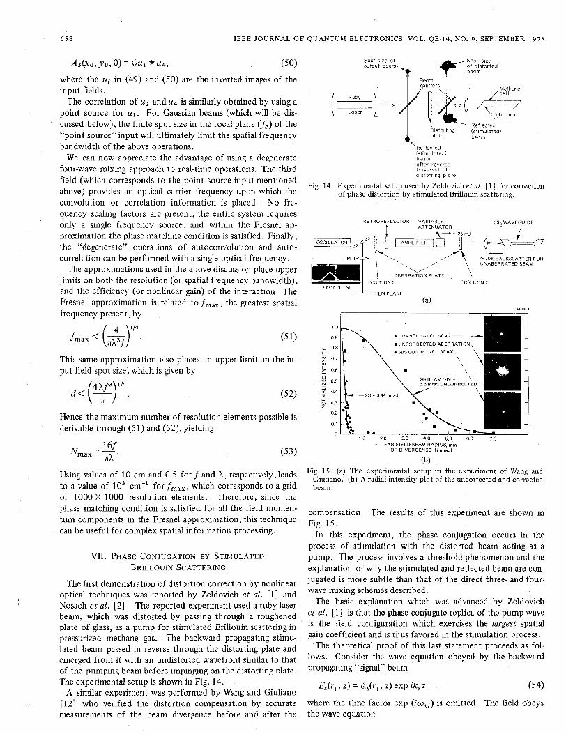
(b) Fig. 15. (a) The experimental setup in the experiment of Wang and
Giuliano. (b) A radial intensity plot of the uncorrected and corrected beam.
compensation. The results of this experiment are shown in Fig. 15.
In t h s experiment, the phase conjugation occurs in the process of stimulation with the distorted beam acting as a pump. The process involves a threshold phenomenon and the explanation of why the stimulated and reflected beam are con- jugated is more subtle than that of the direct three- and four- wave mixing schemes described.
The basic explanation which was advanced by Zeldovich et al. [l] is that the phase conjugate replica of the pump wave is the field configuration which exercises the largest spatial gain coefficient and is thus favored in the stimulation process.
The theoretical proof of this last statement proceeds as fol- lows. Consider the wave equation obeyed by the backward propagating “signal” beam
Es(rI, z ) = &,(rI, z) exp iksz (5 4)
where the time factor exp (iw,,) is omitted. The field obeys the wave equation
YARIV: PHASE CONJUGATE OPTICS AND REAL-TIME HOLOGRAPHY 6 5 9
a2 The sum of the second and third terms is zero in virtue of (61). V2E,(r1, z ) + 4 P € E, = P 2 PNL ("I We next multiply (65) by Jdrf;(r,,z) which, using (62),
where PNL accounts for the acoustooptic interaction with the laser pump wave. dCi 1
I a2 bs/azz I << I k, (ab,/az), I k,' b, I 7 and defining 0: = (a'/ ax') t (a2/ay2) , leads to with
leads to
Using (54) in ( 5 5 ) , recognizing that k,' = w:pe7 assuming -+ 5 gik(Z) ck(z ) = 0 dz k = O
38 , i 1 az 2k, 2 - + - 0: b, -I -g(rl, 2 ) 8, = 0
where g(rl, z) is the local gain exercised by the signal wave due to stimulated Brillouin interaction with the pump wave
bL(rl ,z) exp -ikLz.
Under conditions of very short phonon lifetimes, the gain g can be shown to be proportional to the pump intensity
where A is given by n'p2eon8
CY pu2 A' A =
and where X is the laser wavelength, p = photoelastic coeffi- cient, n is the index of refraction, CY the sound (intensity) ab- sorption coefficient (at the frequency v , , , , ~ = ( ~ ~ v / c ) v ) , p the material mass density, and u the velocity of sound in the medium.
If we neglect the depletion of the laser intensity and the losses at the laser frequency, then the laser field
EL (rl z ) = bL (rl, z ) exp - ikLz (59)
obeys
abL i az 2kL
0: b L = 0.
We note that since k, - kL _N kL , we will assume in the following k, kL = k .
Consider a system of functionsfk(rl, z ) such that
and
Jf?(rl, z ) f k ( r l , z , drl = 6 ik . (62)
Choose the function fz such that it coincides within a constant B with the laser field
bL(r1, z ) = Bfz(r1, z>. (63)
The remaining members of the set fk are generated starting from the orthogonality relation (62). The sought field bs(rl, z ) is expanded in the form of
gik(z)=AB2 d~~IfO(~lrZ)12f~(~l,Z)fk(~~,Z). I (67)
If the intensity I fo(ri, z ) l 2 of the laser field fluctuates strongly as a function of rl, then it follows from (67) that in general the partial overlap of maxima and minima of I f0(rl, z ) l 2 and f?(rL, z)fk(rl , z ) as well as the complex nature of these func- tions will cause gjk to be a small number except for go,, since
go, =AB' dr, I fo(rl, Z ) l 4 s (68) and no cancellation occurs. It follows that under these condi- tions the coefficient Co grows (with distance) more rapidly than the other Ci so that after a sufficient distance, the field 8, is given according to (64)
m
&drl > z ) = ck(z) fk ( r l 7 z> co ('1 fo (rl 3 z , k=O
i.e., the Stokes field generated by stimulated Brillouin (back) scattering is the complex conjugate of the incident laser field and is thus in the proper form to correct in its backward travel for the phase distortions undergone by the laser field.
We note that if fo(r1, z ) is not a strongly fluctuating function of rl then goo and gji will be of the same order of magnitude and the preferential growth of CO, which leads to phase conju- gation, will not take place. The introduction of additional phase aberration in front of the Brillouin cell may thus im- prove the phase conjugation.
In the above derivation, no initial boundary for Ci(z) was specified, since no input exists. It is assumed that the input fields are due to zero point vibrations of the electromagnetic field at the Stokes' frequency.
Before concluding it may be useful to review some of the main directions and possibilities which are already evident in this new field.
The work of Zeldovich et al. [ l ] points the way toward using phase conjugation techniques including stimulated Brillouin and Raman scattering in real time for the correction of distortion in the atmosphere and in passive and active optical components. These may be especially important in high power lasers where the optical integrity of wavefronts is a problem of serious concern. Phase conjugators incorporated into high power laser oscillators can yield the full available power in the form of a diffraction limited beam. In the case of satellite communication through the atmosphere, we can envisage a weak probing beam transmitted from a satellite to earth through the atmosphere. The beam is conjugated, amplified to the requisite power level, and retransmitted through the atmosphere, reaching the satellite as a diffraction limited spot size.
A second class of applications [ 161 , [ 171 involves the use of
660 IEEE JOURNAL O F QUANTUM ELECTRONICS, VOL. QE-14, NO. 9, SEPTEMBER 1978
phase conjugation for real-time holographic applications. These include image transmission through fibers, as well as convolution and correlation as discussed above. In these cases, it will be important to perform these experiments on a CW basis with moderate power levels. One approach in this direc- tion was demonstrated by Bloom, Liao, and Economou [9] who demonstrated four-wave phase conjugation using the resonantly enhanced Kerr nonlinearity of atomic sodium vapor [19]. Another approach is to use multimode optical waveguides, solid or filled with some suitable fluid, as the medium for wave conjugation. An analysis of this possibility [20] shows that all the main features of the bulk interaction are preserved in the case of fibers. The number of resolution elements in the pictorial field cannot exceed the number of guided modes in the fiber. Due to the large intensities which result in small diameter (10-100 pm) fibers and the confine- ment of the radiation over large lengths, CW phase conjugation with power levels of -1 W are estimated.
The amplification property of the transmitted or reflected wave can be used in image amplification. By using simul- taneously a number of pump waves of different wavelengths, we should be able to achieve amplification of color images.
To summarize: Phase conjugation by nonlinear techniques has been shown formally to be analogous to holography. This, in combination with the added features of real-time operation, amplification, and oscillation, promises the potential of many new and interesting applications involving the processing and restoration of optical wave fronts.
ACKNOWLEDGMENT I would like to express my appreciation to my colleagues
and students who participated with me in developing these ideas: V. Wang, R. L. Abrams, and V. Evtuhov at the Hughes Research Laboratories, Malibu, and P. Yeh, D. Fekete, J. AuYeung, and D. M. Pepper at the California Institute of Technology.
REFERENCES
[ l ] B. Y. Zeldovich, V. I . Popovichev, V. V. Ragulskii, and F. S. Faisullov, “Connection between the wave fronts of the reflected
and exciting light in stimulated Mandel’shtam-Brillouin scatter- ing,”Sov. Phys.-JETP,vol. 15,p. 109,1972. 0. Y. Nosach, V. I . Popovichev, V. V. Ragulskii, and F. S. Faisullov, Sov. Phys.-JETP,vol. 16, p. 435, 1972. A. Yariv, “Three-dimensional pictorial transmission in optical fibers,”Appl. Phys. Lett., vol. 28, p. 88, 1976. A. Yariv, “On transmission and recovery of three-dimensional image information in optical waveguides,” J. Opt. SOC. Amer., vol. 66, p. 301,1976. R. W. Hellwarth, “Generation of time reversal wavefronts by non- linear refraction,” J. Opt. SOC. Amer., vol. 67, p. 1, 1977. A. Yariv and D. M. Pepper, “Amplified reflection, phase conjuga- tion, and oscillation in degenerate four-wave mixing,” Opt, Leit., vol. 1, p. 16,1977. S. L. iensen and R. W. Hellwarth, “Observation of the time- reversed replica of a monochromatic optical wave,” Appl. Phys. Lett., vol. 32, p. 166, 1978. D. M. Bloom and G. E. Bjorklund, “Conjugate wave front gener- ation and image reconstruction by four-wave mixing,” Appl. Phys. Lett., vol. 31, p. 592, 1977. D. M. Bloom, P. F. Liao, and N. P. Economu, “Observation of amplified reflection by degenerate four-wave mixing in atomic sodium vapor,” Opt. Lett., vol. 2, p. 158, 1978. D. M. Pepper, D. Fekete, and A. Yariv, Appl. Phys. Lett., to be published. P. V. Avizonis, F. A. Hopf, W. D. Bamberger, S . F. Jacobs, A. Tomita, and K. H. Womack, “Optical phase conjugation in a lithium-niobate crystal,” Appl. Phys. Lett., vol. 31, p. 435, 1977. V. Wang and C. R. Giuliano, “Correction of phase aberrations via stimulated Brillouin scattering,” presented at the 1977 IEEE OSA Conf. Laser Engineering and Applications, Washington, DC, June 1977, Paper 17.6; also, Opt. Lett.,vol. 2, p. 4,1978. B. Ya Zeldovich and V. V. Shkunov, “Wavefront reproduction in stimulated Raman scattering,”Sov. J. Quantum Electron. (English transl.), vol. 7, p. 610, 1977. See, for example, R. W. Minck, R. W. Terhune, and C . C. Wang, “Nonlinear optics,” Appl. Opt., vol. 5, p. 1595, 1966; or A. Yariv, Quantum Elecrronics,~2nd ed. New York: Wiley, 1975. S. E. Harris, “Proposed backward wave oscillation in the infra- red,” Appl. Phys. Lett., vol. 9, p. 114,1966. A. Yariv, “Four-wave mixing as real time holography,” Opt. Commun., to be published. D. M. Pepper, J. AuYeung, D. Fekete, and A. Yariv, “Spatial convolution and correlation of optical fields via degenerate four- wave mixing,” Opt. Lett., to be published. J. W. Goodman, Introduction to Fourier Optics. New. York: McGraw-Hill, 1968. R. L. Abrams and R. C. Lind, “Degenerate four-wave mixing in absorbing media,” Opt. Lett., vol. 2, p. 94, 1978. A.Yariv, J. AuYeung, D. Fekete, and D. M. Pepper, “Image phase compensation by four-wave mixing in optical fibers,” Appl. Phys. Lett., vol. 32, p. 635, 1978.


![Frequency conversion by nonlinear optics: narrow bandwidth sources and applications · 2020. 3. 10. · EM- elds can be generated. Text-books by Zernike et al. [2], Shen [3] and Yariv](https://img.pdfslide.net/doc/110x75/60e62dacb34d2074ac580295/frequency-conversion-by-nonlinear-optics-narrow-bandwidth-sources-and-applications.jpg)