Embed Size (px)
Citation preview
Pilots Manual
Cyclone 294

2
WARNING!!! Use of the powered paraglider is at your own risk.
WARNING!!!
YOU MUST READ THIS MANUAL AND AGREE TO THE CONDITIONS OF USE
BEFORE USING YOUR PARAJET CYCLONE 294
Bear in mind that you will use the Parajet Cyclone and paraglider at your
own risk. The Cyclone 294 is an extremely powerful Paramotor and should
be used only under direct tuition of a qualified instructor or by a pilot that
has received and passed a Paramotor course equivalent to the BHPA
Paramotor course. Due to the inherent risk in flying the Cyclone or any
motorized paraglider, no guarantee of any kind can be made against
aidents, bodily injury and/or death. Be sure, therefore, to make all required
checks on the power unit and paraglider before every flight. Never try to fly
if you find any part of your Cyclone damaged or suspect a malfunction.
NB. This manual is NOT a substitute for flight training. Proper training is essential.
The Cyclone 294 is powerful enough to stall your wing exercise extreme caution when
flying with this unit.
This engine has been designed to work with Mobil One Racing 2T Fully Synthetic 2
stroke racing oil. 2 stroke oil can vary hugely in its composition and the wrong oil will
damage the engine and can result in engine malfunction. Failure to use Parajet’s
recommended 2 Stroke oil will result in the engine warranty being void.
3
WARNING!!! Use of the powered paraglider is at your own risk.
INTRODUCTION
Congratulations on the purchase of your Parajet Cyclone 294 for motorized
paragliding. We guarantee you have made an excellent choice and wish you
many enjoyable flights and just as many safe landings with your Cyclone
294.
Our power units have been designed and produced in our UK factory to
exacting standards. Each Cyclone 294 is carefully inspected before leaving
the factory. This manual and Parajet power unit carry a placard that clearly
indicates a limit to flight hours. Therefore, use your Cyclone 294 within the
limits indicated.
Should the purchaser modify the Cyclone 294 so as to change its original
specifications, the manufacturer’s warranty becomes invalid.
Please read and be sure that you thoroughly understand this manual before
flying the Cyclone 294. If there is any terminology or anything else in this
manual which you do not understand, please contact your dealer for
clarification.

4
WARNING!!! Use of the powered paraglider is at your own risk.
Table of Contents
WARNING!!! ................................................................................................ 2
PRE-FLIGHT CHECKS ..................................................................................... 5
FLIGHT SAFETY PRECAUTIONS ...................................................................... 6
SOME GOLDEN RULES !!! ............................................................................. 7
PRE-ASSEMBLY CHECK ................................................................................. 8
List of Components ......................................................................................................... 8
FITTING THE RADIATOR ............................................................................... 9
Filling the radiator. .................................................................................... 14
FITTING THE PROPELLER BLADES ............................................................... 16
ASSEMBLING THE 3-PIECE PROPELLER GUARD ........................................... 17
Charging the Cyclone LiPo battery: ............................................................ 18
REDUCTION BELT ADJUSTMENT ................................................................. 19
FITTING THE WEIGHT-SHIFT HARNESS ....................................................... 20
ADJUSTING THE WEIGHT SHIFT HARNESS ........................................................ 21
MIXING FUEL AND OIL ............................................................................... 22
Caution! ..................................................................................................................... 23
PRIOR TO STARTING THE ENGINE .............................................................. 24
Warning!!! - Stay Clear of this Area !!! ..................................................................... 24
STARTING THE ENGINE AND ENGINE TEMPERATURE ................................. 25
STOPPING THE ENGINE ........................................................................................... 28
RE-STARTING THE ENGINE .................................................................................... 28
ENGINE TEMPERATURE.......................................................................................... 28
CARBURETOR ADJUSTMENT ...................................................................... 29
ENGINE RUNNING IN PROCEDURE ............................................................. 30
MAINTENANCE SCHEDULE ......................................................................... 32
EVERY 5 HOURS ........................................................................................................ 32
EVERY 10 HOURS ...................................................................................................... 32
EVERY 50 HOURS ...................................................................................................... 32
TROUBLE SHOOTING .................................................................................. 33
STORAGE FOR A LONG PERIOD AND USE THEREAFTER .............................. 34
5
WARNING!!! Use of the powered paraglider is at your own risk.
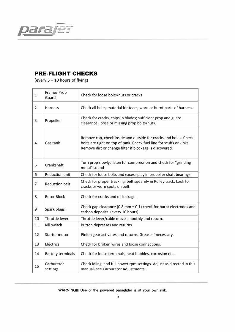
PRE-FLIGHT CHECKS (every 5 – 10 hours of flying)
1 Frame/ Prop
Guard Check for loose bolts/nuts or cracks
2 Harness Check all belts, material for tears, worn or burnt parts of harness.
3 Propeller Check for cracks, chips in blades; sufficient prop and guard
clearance; loose or missing prop bolts/nuts.
4 Gas tank
Remove cap, check inside and outside for cracks and holes. Check
bolts are tight on top of tank. Check fuel line for scuffs or kinks.
Remove dirt or change filter if blockage is discovered.
5 Crankshaft Turn prop slowly, listen for compression and check for “grinding
metal” sound
6 Reduction unit Check for loose bolts and excess play in propeller shaft bearings.
7 Reduction belt Check for proper tracking, belt squarely in Pulley track. Look for
cracks or worn spots on belt.
8 Rotor Block Check for cracks and oil leakage.
9 Spark plugs Check gap clearance (0.8 mm ± 0.1) check for burnt electrodes and
carbon deposits. (every 10 hours)
10 Throttle lever Throttle lever/cable move smoothly and return.
11 Kill switch Button depresses and returns.
12 Starter motor Pinion gear activates and returns. Grease if necessary.
13 Electrics Check for broken wires and loose connections.
14 Battery terminals Check for loose terminals, heat bubbles, corrosion etc.
15 Carburetor
settings
Check idling, and full power rpm settings. Adjust as directed in this
manual- see Carburetor Adjustments.

6
WARNING!!! Use of the powered paraglider is at your own risk.
FLIGHT SAFETY PRECAUTIONS
• The Parajet Cyclone 294 engine has been run-in prior to shipment. This means that
your Cyclone 294 is ready to fly. It is important however that excessive throttle is
NOT used for at least the first 10 hours of flying. For example, do NOT depress the
throttle fully for more than 30 seconds at a time. A well run in engine will
outperform an engine that has been run at full power for long periods right from the
start. You can potentially damage a new engine with excessive throttle.
• The Cyclone 294 Paramotor unit is to be used only after having received adequate
and proper training from a qualified motor paragliding instructor.
• Max weight capacities for paramotor pilots flying a Parajet Cyclone 294 range
paramotor:
Parajet Cyclone 294 Model Max Pilot Weight
Macro 250Kg
• The Cyclone 294 should only be used with canopies designed for motor paragliding.
• Always conduct a check of all components before every flight.
• Always wear a helmet, flight shoes and gloves when flying the Cyclone 294.
• Always stay clear of moving parts such as propellers, pulleys and belt.
• Always stay clear of hot engine parts and muffler.
• Do not fly low level over water, woodland, or potentially hazardous landing areas. Do not fly into controlled airspace or over built up areas, it essential always to consider a safe landing area should you experience an engine failure or loss of power.
• Before starting the engine check the area is clear and shout “CLEAR PROP”
• Always ensure that the power unit is switched off when not in use. The main power
switch is to be found on the left side of the machine just behind the harness.
7
WARNING!!! Use of the powered paraglider is at your own risk.
SOME GOLDEN RULES !!! 1. Never place your engine downwind of your wing.
2. Have you enough fuel to get there? Better too much than too little!
3. Check for any loose articles that could trail or fall into the propeller while flying and
fasten them securely.
4. If you spot a problem, not matter how small, deal with it NOW!
5. Always put on and fasten your helmet before clipping into the harness.
6. Always carry out full pre-flight checks before launching.
7. Don’t fly into danger – over water, tree, power lines etc where an engine failure will
leave you in trouble.
8. Try not to fly in the turbulence of your own wake or that of others, especially at low
altitude.
9. Except for collision avoidance, making a sharp turn against the torque effect during
steep climbs can be dangerous: you may rapidly stall and enter a spin.
10. Avoid downwind low flying: it drastically reduces your options.
11. Be sensitive to mechanical problems early. A noticeable change in engine tone or a
new vibration may spell trouble. Land and check it out!
12. Remember, not everyone enjoys your engine noise. Care must be taken when flying
near livestock.
13. Never take-off towards areas of potential rotor, towards trees or buildings on the
lee side of a hill.
14. Never touch any part of the propeller guard when the engine is running.
15. Always be aware of the weather, never fly if large cumulus clouds are brewing and
never fly in the rain.
17. Never fly below the lee side of a hill, rotor is dangerous!!

8
WARNING!!! Use of the powered paraglider is at your own risk.
PRE-ASSEMBLY CHECK Be sure to identify all components after unpacking your Cyclone 294 unit. If any parts
are found defective do not assemble. Contact your dealer or the manufacturer
immediately.
Parajet International Ltd: Main enquiry Line + 44 1747 861368
List of Components 1. Main Chassis 8. 3 Piece Propeller Guard
2. Drive Pulley 9. Radiator
3. Propeller Retaining Disc 10. Air Box and Carburettor
4. Main Rotor Housing 10. Carbon Fibre Propeller Blade
5. Main On/Off Switch 12. Muffler and Exhaust Pipe
6. Harness 13. Fuel Filler Cap
7. Rubber Skid Pads 14. Fuel Tank
10
11
6
5
13
12
8
2
7
4
3
1
9
14

9
WARNING!!! Use of the powered paraglider is at your own risk.
FITTING THE RADIATOR
Your Parajet Cyclone 294 paramotor and radiator will arrive unassembled. This is the critical coolant system for the engine and must be installed correctly. Any leakage will lead to engine damage.
Start this process before fitting the cage and propellers.
Parts:
Step 1
Mixing engine coolant.
A good quality anti freeze/summer coolant should be used and mixed to the manufacturers recommendations.
In a separate container Mix up 2 litres of coolant/water solution ready for filling up the machine. You will not require all two litres.
This should be decanted in to a convenient pouring device ready for filling up the machine.
Jubilee Clip
Radiator Hose
Radiator Filler Cap
Radiator

10
WARNING!!! Use of the powered paraglider is at your own risk.
Step 2
With the Parajet Rotron Macro 294 paramotor stood upright orientate the radiator so the radiator mountings line up with their corresponding mounts on the frame. The radiator will only fit on in one direction.
Facing the propeller side of the engine (not the harness side), the filler neck of the radiator will be on the left of the radiator.
Pass the tubular legs of the radiator through the plastic mountings in the frame and firmly push on top of the radiator to locate it in its mounts.
Picture 1

11
WARNING!!! Use of the powered paraglider is at your own risk.
Picture 2. The fitting the radiator in the correct orientation.
Step 3
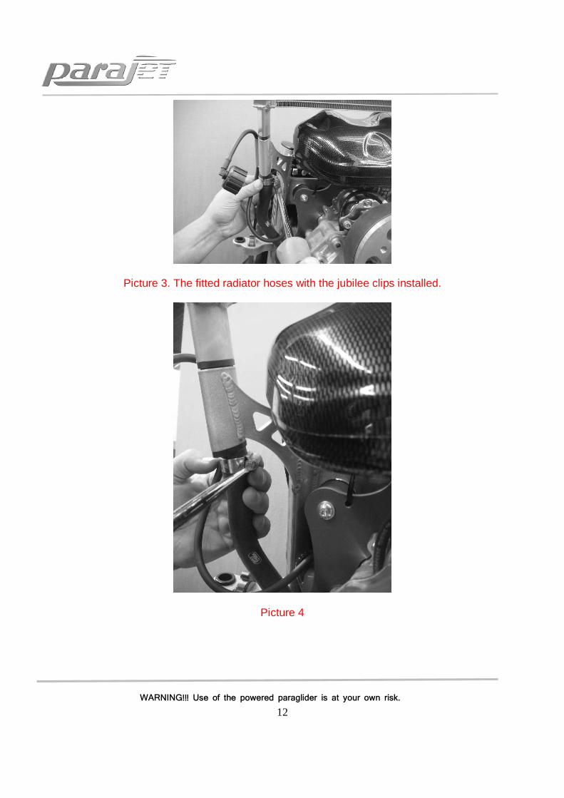
both radiator hose inlet and outlet are fitted to the engine. They will however need to be fitted to the radiator.
First feed the jubilee clips over the radiator hose. Then slip the radiator inlet and outlet hoses over the radiator tubes which protrude through the plastic chassis mounts. Make sure they are firmly stopped against the plastic frame mounts.
The jubilee clip should be positioned 1cm from the end of the coolant hose on both the inlet and outlet hose side.
Using a large flat head screw driver tighten the jubilee clip to ensure there can be no leakage of coolent.
12
WARNING!!! Use of the powered paraglider is at your own risk.
Picture 3. The fitted radiator hoses with the jubilee clips installed.
Picture 4

13
WARNING!!! Use of the powered paraglider is at your own risk.
Step 4
Fit the radiator cap on to the radiator
Picture 5.

14
WARNING!!! Use of the powered paraglider is at your own risk.
Filling the radiator.
Warning Engine should not be flown without the radiator being filled. Failure to do so will result in engine malfunction which will void the warranty. This may also lead to injury or death.
Warning never open the radiator cap when the engine is hot this may cause injury
Warning engine coolant can be corrosive and must be washed of if spilt on the paramotor.
Filling the paramotor with coolant can be done with the cage and propeller installed.
The paramotor can be rolled on to its side so the filler neck is the highest point of the system, this is best done with two people, one to support the paramotor and one to fill it up.
Caution: To avoid damage to paint this should be done on a soft surface, cardboard or a rubber mat.
Remove the radiator cap. Roll the paramotor on to its side as shown bellow.
Picture 8. Showing the paramotor being filled.
The radiator should be slowly filled to the brim with coolant.
Once full refit the radiator cap before rolling the paramotor back on to its base.
You should run the engine for one minute and the leave it to cool down

15
WARNING!!! Use of the powered paraglider is at your own risk.
Check the paramotor rigorously for any sign of leakage from the installed parts
Then do the coolant filling procedure again to check the radiator is full to the brim and if required refill. This running helps bleeds any air out of the system.
Once refilled refit the radiator cap and roll the paramotor on to its base.
Your coolant system is now fitted, full and ready for use.

16
WARNING!!! Use of the powered paraglider is at your own risk.
FITTING THE PROPELLER BLADES
Fit the 3 propeller blades to the driven pulley in the order outlined below
1. Insert 2 of the 6 (M8 x 60mm) bolts into the prop disc and locate a single blade in
position. Ensure that each bolt has both a split spring washer then normal spreader
washer located on its shank before locating in the prop disc.
2. Locate a single blade in position on these two bolts and lightly screw the bolts into
position on the driven pulley.
3. Follow the same procedure for each blade but do not tighten the bolts until all three
blades are in position.
4. Finally tighten each bolt with equal torque hand tight only (be careful not to over
tighten and crush the carbon fibre propeller hubs)
Note – When installing the propeller, the propeller blade bolts should not be over-
tightened or the base of the propellers could be damaged, distorted and weakened.
When installing the propeller blades make sure to match the balancing dots on each blade with the corresponding dots on the adjacent blade. The dots can be located on at the bas of each blade.
Prop Disc
M8 x 60
Screws Driven
Pulley
Propeller Blade

17
WARNING!!! Use of the powered paraglider is at your own risk.
ASSEMBLING THE 3-PIECE PROPELLER GUARD
Fit the three pieces together as shown in the illustration below. The two lower sections should
be clicked into position first. The top section can then be clicked into position, to do this lightly
press the curved central support onto its aerofoil connector and simultaneously locate the two
circular side connectors. DO NOT PRESS FIRMLY INTO POSITION UNTIL THE OUTER RING
CONNECTORS ARE LOCATED. Next locate the left and right hand outer ring connectors. Lightly
press them into position but do not depress the button clips. Now that all the connection points
are in position, the central upright should be firmly pressed into position and the button clip
depressed to lock this position. The outer ring connectors can now be locked in also. This
process require a little technique, but once developed can be snapped together and
disassembled in under a minute. This is the fastest and most durable design of propeller guard.
Note - The propeller guard is designed to prevent canopy lines and other foreign objects from
being drawn into the propeller and are not intended to protect the pilot. Therefore,
always use extreme caution and never touch any part of the propeller guard while flying or
running the engine on the ground.
Left: Internal guard
vertical support slots
through chassis holder
before lower connectors
are locked in position
Right: Upper cage
support is located before
being snapped firmly into
position.

18
WARNING!!! Use of the powered paraglider is at your own risk.
Charging the Cyclone LiPo battery: Important! Caution! Always disconnect the battery connector when not using the
Cyclone for more than 4 days. If you do not you will risk damaging the battery.
WARNING: Do not try to start your engine if the battery is showing signs of running
low. The starter motor will start to spin slower, due to the nature of LiPo batteries
they drain very quickly once the voltage drops below a certain level. If you continue to
try starting the engine once the battery voltage has dropped you will risk damaging
the battery or starter motor seriously.
Your Parajet Cyclone is supplied with a 14.8volt high power Lithium Polymer battery. This type
of battery has the highest energy density of any type of battery available today. It also has many
other advantages such as
1. It can be fully charged in under one hour
2. It has an extremely high discharge rate, delivering fully energy to the start motor
instantly which results in the easiest start procedure
3. The battery is extremely light weight and compact and can deliver over 80 starts on a
single charge
Charge procedure
1. Switch on Battery Charger by:
a. Plugging in the mains 240volt or 110volt power lead (lead supplied in box)
2. Using the ‘Batt Type’ button press until ‘LiPo’ is displayed on the screen
3. Press the ‘ENTER Start/Stop’ button to set the charging amps and number of cells. Use
the Inc + button to set the figures as follows:
4. 4.0A 4CL (The charger must first read these figures to charge correctly)
5. Plug the battery you wish to charge into the charger by first connecting the small white
multi pin plug into the 4S socket on the small adaptor board supplied. Then connect the
larger blue battery terminal plug to the charger
6. Once both battery connectors are connected press and hold the ENTER Start/Stop
button for 3 seconds and the charge and balance procedure will begin.
IMPORTANT: Stop using the battery once the cranking speed has clearly reduced and
re-charge the battery.
IMPORTANT: You should charge the battery using the procedure
described above every time you charge as this will keep the battery in the
best possible condition. This is known as balance charging your battery
and it maintains each individual cell within the battery pack from
becoming damaged due to voltage imbalance.

19
WARNING!!! Use of the powered paraglider is at your own risk.
REDUCTION BELT ADJUSTMENT
The transmission belt is well adjusted at the time of shipment, but it could become slack
during initial operations. When necessary adjust it so as to keep it always in an optimum
state of tension. Referring to the picture below adjust reduction belt tension as outlined
in these steps. A high pitch revving noise from the engine is a sign that the belt has
become loose. Be sure to tighten the belt as soon as possible or you could damage it.
1. Remove the propeller from the driven pulley.
2. Loosen the prop shaft retaining nut and then screw (A) NB. They will be very tight!!
3. Insert the 5mm hex key into the hole in the side of the prop shaft. (B)
4. To tension the belt, firmly rotate the shaft clockwise. This in turn will enable the
eentric prop shaft to increase the belt tension. It will be very stiff to move.
5. Once the belt has reached the required tension simply re-tighten the prop shaft
retaining screw and nylock nut. (see diagram below for belt tension setting)
A
B
Left: Prop Shaft
retaining screw also
has a nylock security
nut on the opposite
end. Loosen this 4
turns before undoing
main screw (A)
Right: Use 5 mm hex
key provided and slot
into drilled hole in
propeller shaft. Then
rotate propeller shaft
hard clockwise to
tighten or counter
clockwise to loosen.
Left: Shows correct belt
tension. You should be
able to push 2 - 3mm
movement with your
thumb.
2 – 3 mm

20
WARNING!!! Use of the powered paraglider is at your own risk.
FITTING THE WEIGHT-SHIFT HARNESS The weight-shift design enables pilots to control flight direction purely by shifting centre
of gravity in the harness. To do this simply lean in the desired direction and swing one
leg over the other to aentuate the turn. This creates a very efficient smooth turn which
requires no brake input.
Fitting the weight-shift harness:
1. Start by locking the harnesses upper
retaining bar onto the chassis as shown
below. NB. Ensure Button Clip locates
properly and pops into hole as arrowed..
2. At the base of the harness on the
reverse side there are 2 steel rings
pressed into the webbing tabs. These
line up with 2 corresponding M6
threaded inserts located in each chassis
upright approximately 10cm from the
base.
3. Using the two M6 x 12mm socket screws
and large flange washers tighten the harness
webbing into position against the chassis
uprights.
4. At the front of the harness are 2 webbing
loops. Using the stainless steel shackles
attached to the swing arms attach the
webbing loops to the first hole in the swing
arm.
5. Attach carabiner connection points to the
corresponding weight setting on the swing
arms. (See next page)

21
WARNING!!! Use of the powered paraglider is at your own risk.
ADJUSTING THE WEIGHT SHIFT HARNESS To adjust this type of harness to the optimum weight setting, position the hang-point
mallion and off-set pin as shown below. The weight ranges are given in the diagram.
IMPORTANT – If the harness is not set up correctly it will result in poor handling and
uncomfortable flying. It is vital therefore that the steps described below are followed
aurately.
CAUTION!!! If the pilot is too heavy for the chosen harness setting this will cause the
Cyclone 294 to ride up on the pilots back. This makes for an uncomfortable flying
position and also causes the top of the propeller guard to press near to the paraglider
brake handles which is potentially very dangerous. If you suspect this it is important that
you land as soon as possible and re-set the hang points moving them one or two
settings forward.
NOTE – Due to the dynamic nature of this harness it may take some flying time to
become austomed to the flying style. It may also take a few flights to decide which
hang-point position is most comfortable and effective for you. You will notice that on
full power the flying position is more upright and that when you reduce throttle the
position is more laid back. The engine off position is designed to be similar to the free
flying position which is more comfortable and improves weight shift for thermalling.
(65kg – 75kg)
(55kg – 65kg) (100 – 110kg) (75kg – 90kg)
NB. The Cyclone 294 weight shift harness is designed to offset the torque reaction of
the propeller. This enables the pilot to fly straight even on full power. The system uses
the pilot’s weight to counter the torque by off-setting both karabiners to the right as
the pilot sits in the harness. See arrows above.
Important: Always ensure that both rubber off-set covers are fully tightened in position
pointing to the left as you look at the harness before you get in to fly (as above) If you
are sitting in the harness they should both point to the right. This is essential!!

22
WARNING!!! Use of the powered paraglider is at your own risk.
MIXING FUEL AND OIL
This engine has been designed to work with Mobil One Racing 2T Fully Synthetic 2
stroke racing oil. 2 stroke oil can vary hugely in its composition and the wrong oil will
damage the engine and can result in engine malfunction. Failure to use Mobil one will
result in the engine warranty being void.
Use only unleaded regular petrol (95 - 98 octane) and Mobil one oil for air-cooled
engines. Mobil 2 Stroke synthetic racing oil available on our online shop.
Other oils can be substituted but any oil used should be for air-cooling chemical
synthesis and medium rotation. Check with your manufacturer or our service centres or
any authorised Parajet dealer for the best type of oil available in your area.
1. Mix petrol and oil at a ratio of 30:1 (660ml Oil for 20 litres of unleaded petrol)
2. Shake and mix fuel and oil well.
3. Always use freshly mixed petrol and oil not more than 4 weeks old
4. Use standard unleaded fuel (95 – 98 octane is standard)
5. Only use recommended oil.
FILLING THE FUEL TANK
1. Remove the tank cap. (rotate counter clockwise)
2. Pour the fuel mixture into the fuel tank.
3. Fill tank to 20mm below level of filler (11.5 litres) For maximum flight range fill to
the top (3- 4mm beneath cap level total of 12.5 litres)
4. Tighten fuel cap securely. (be sure not to cross thread the cap as it will not seal
correctly)
5. For flight less than one hour it will only be necessary to half fill the tank.
Note
• Do not fill above this level.
• Be careful of fuel spillage and wipe dry should any spill.
• Be sure the fuel is clean. Although there is a fuel filter in the fuel tank Dirt, dust
and other foreign objects can clog the filter and cause the engine to run poorly
or stop.

23
WARNING!!! Use of the powered paraglider is at your own risk.
Caution!
• Never leave the engine running when refueling.
• Observe the ‘No Fire’ rules; keep all inflammable objects well away from fuel.

24
WARNING!!! Use of the powered paraglider is at your own risk.
PRIOR TO STARTING THE ENGINE
1. Check carefully the surrounding area before taking out your unit.
2. Be sure to choose a flat bit of ground which is well ventilated. Do not start the
engine indoors or other poorly ventilated areas.
3. Be sure nothing is within 3 meters of your unit.
4. Conduct a complete pre-flight check of your unit, especially looking for oil and gas
leaks. Check the unit carefully for loose nuts or bolts, bent or damaged frame or any
other type of damage.
5. Check level of fuel mixture. Be sure it is freshly mixed (less than 4 weeks old).
6. Check immediate area near the propeller for lines, ropes, clothing and anything that
could be caught in the moving propeller or drive pulleys.
7. Pilots with long hair should be especially careful to cover their head.
Warning!!! - Stay Clear of this Area !!!
• Warn persons nearby before starting the engine- Make it a habit to shout ‘Clear
Prop’ in a loud and clear voice.
• The turning propeller can cause considerable damage and injury.
• Do not start engine indoors or other poorly ventilated areas.
• Be sure area is free from anything that could be entangled in propeller.
• Use only freshly mixed 30:1 regular petrol and oil recommended by Parajet. The
most common reason for engine damage is improper oil or petrol
• Only fill tank with the engine off and only after it has cooled down.
• Follow all “No Fire” rules.
Warning!!
Keep clear of moving propeller
Keep objects away from propeller
Danger Area. Always ensure
this area is clear of people
25
WARNING!!! Use of the powered paraglider is at your own risk.
STARTING THE ENGINE AND ENGINE TEMPERATURE
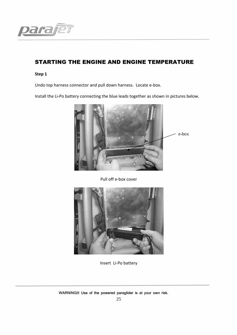
Step 1
Undo top harness connector and pull down harness. Locate e-box.
Install the Li-Po battery connecting the blue leads together as shown in pictures below.
Pull off e-box cover
Insert Li-Po battery
e-box

26
WARNING!!! Use of the powered paraglider is at your own risk.
Connect blue connectors
Step 2
Turn on the Cyclone 294 at the Power On/Off switch. Location shown in the picture
above.
Power On/Off Switch

27
WARNING!!! Use of the powered paraglider is at your own risk.
Step 3
On the 294 there is a fuel pump situated below the air box as shown in the picture below.
This should be pumped until firm. The fuel can be viewed rising up the fuel line and filling the fuel pump bulb. One complete pump of the fuel bulb when it is full of fuel will allow an easy start of the engine.
(Be sure not to pump too much fuel in to the engine as this may cause flooding)
If the paramotor does not start easily use the auxiliary lead provided and attaches it to any 12V high amp leisure or car battery.
The engine should be turned over with a slight amount of throttle applied until it starts
Be sure to brace the machine properly on starting as it produces large amounts of thrust.
Warm the engine for at least 2 minutes before flight and allow idle speed to settle.
Warning: When the engine is cold it will not be possible to aelerate the engine. Wait until engine is warmed up to apply throttle.

28
WARNING!!! Use of the powered paraglider is at your own risk.
Start Button (Green)
STOPPING THE ENGINE 1. Stop (kill) the engine only after releasing the throttle grip and allowing the engine to
return to idle speed.
2. Hold down the Stop button until the engine dies completely.
3. Turn off the Main switch. This cuts power to the starter motor and has been designed
as a safety measure. Make it a steadfast rule to turn off the Main Power to avoid
inadvertent starts and aidents.
RE-STARTING THE ENGINE
In flight, the pilot can restart the engine when flight conditions are suitable. Be sure the
throttle is in idle position when re-starting the engine.
ENGINE TEMPERATURE As this engine is water cooled damage to the radiator or the engine overheating will cause the engine to overheat. The Temperature Lamp located above the cruise control knob flashes when the engine overheats. If the Temperature Lamp flashes land immediately. N.B. The temperature lamp may turn on after landing and the engine has stopped running due to heat soak. This will not cause damage to the Rotron 294 Power unit.
Engine Kill Button (RED)
Cruise Control Knob
CW: To Lock
W: To Unlock
Temperature Lamp
Throttle

29
WARNING!!! Use of the powered paraglider is at your own risk.
CARBURETOR ADJUSTMENT
Warning!! The Cyclone 294 is extremely powerful, users should not try to test thrust
unless the unit is placed into a dealer approved thrust rig.
Warning!! Rotary engines are set up to very precise tolerances. Only authorized and
qualified service partners should attempt to adjust the carburetor.
Warning!! Adjustment of the idle screw should not be done with the engine running.
Adjusting the idle screw with the engine running can result in loss of limbs, fingers or
death.
The carburettor has three adjustments
Idle adjustment
Slow running mixture
Fast running mixture
Turning the fast and slow running mixture screws clockwise will lean the fuel mixture. Turning them anti clockwise will make the fuel mixture richer.
If the factory fuel settings are lost contact your main dealer as serious engine damage can be caused by the wrong fuel mixture.
Lean running will cause a failure of the materials used in this engine and should be avoided at all times.

30
WARNING!!! Use of the powered paraglider is at your own risk.
ENGINE RUNNING IN PROCEDURE
The Cyclone 294 engine undergoes a thorough inspection before shipment during which
each engine is run for 1 hour as a preliminary running-in process. For the best engine
performance it is necessary to follow our running in procedure during your first 10 hours
of flying. This is a simple process and most importantly it means that you can fly your
Cyclone 294 right away with no lengthy ground running process.
For the best results it requires that you never remain on full power for more than 30
seconds at a time during flight.
Directions:
After take-off you may remain on full power during climb out for up to 1 minute (max)
It is then important to back-off the power and sit at cruise rpm and fly level for 1 – 2
minutes approx before using full power again.
If you wish to climb high do so in stages climbing on full power for 30 second intervals
then allowing the engine to settle at cruising flight rpm or slow climb for a minute or so.
After the first 10 hours of flying you are free to climb using the throttle for longer
periods….
However….
The key to a long lasting, high performance engine is to treat it with some respect. Do
not dwell on full throttle for long periods as the engine becomes hot and this reduces
the life span of the bearings and mechanical components. As with any engine, using it
well within its designed limits ensures that you will receive the longest life from it.
Resulting in less maintenance costs and servicing time.

31
WARNING!!! Use of the powered paraglider is at your own risk.
PARAJET CYCLONE 294 SPECIFICATIONS
Propeller and Cage Guard
Dimensions (Macro) 1350mm diameter (123cm propeller diameter/ 48.5 inch)
Material Aluminium Duralumin 6082 T6
Engine Specifications
Model Rotron 294
Displacement 294
Type Water Cooled Rotary Engine
Max rpm 7600 rpm
Fuel 30:1 gasoline/ Mobil One Racing 2T Fully Synthetic 2 stroke
racing oil
Capacity (Macro) 14 litres
Starter Electric mains recharge
Propeller 3-blade full carbon fibre Scimitar Design
Guard 3-piece snap-on, quick assembly system.
Reduction 2.5 : 1
Dry weight 36kg Macro
Thrust (Macro) 92 kg
Flight time (Macro) 3.5 hrs With a 65KG Pilot and Revolution 32
Standard equipment Electric starter

32
WARNING!!! Use of the powered paraglider is at your own risk.
MAINTENANCE SCHEDULE
EVERY 5 HOURS
1 Spark plugs Check colour (white or black) burnt electrode. Connector cap
locks with pressure, makes locking sound
EVERY 10 HOURS
1 Air cleaner Remove and wipe clean. If excessively dirty with carbon and oil
then clean with kerosene
2 Air Funnel Wipe with smooth cloth.
3 Muffler
Check for cracks and loose band or bolts. Run finger inside exhaust
pipe –an oily film should be found. No oily film suggests that
oil/gas mixture is too lean so the carburettor needs adjusting.
EVERY 50 HOURS
1 Compression
check
Compression in the cylinder must be no less than 1 pound under
normal reading.
2 Rotor Housing
wall Check for burns near exhaust port and sides of wall.
EVERY 100 HOURS
1 Parajet Service Parajet service by a Parajet UK or authorized Parajet service
centre.
33
WARNING!!! Use of the powered paraglider is at your own risk.
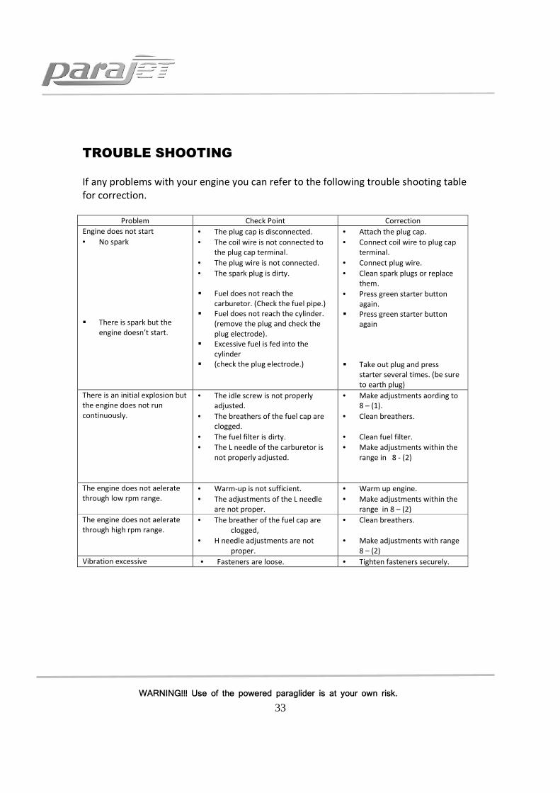
TROUBLE SHOOTING
If any problems with your engine you can refer to the following trouble shooting table
for correction.
Problem Check Point Correction
Engine does not start
• No spark
� There is spark but the
engine doesn’t start.
• The plug cap is disconnected.
• The coil wire is not connected to
the plug cap terminal.
• The plug wire is not connected.
• The spark plug is dirty.
� Fuel does not reach the
carburetor. (Check the fuel pipe.)
� Fuel does not reach the cylinder.
(remove the plug and check the
plug electrode).
� Excessive fuel is fed into the
cylinder
� (check the plug electrode.)
• Attach the plug cap.
• Connect coil wire to plug cap
terminal.
• Connect plug wire.
• Clean spark plugs or replace
them.
• Press green starter button
again.
� Press green starter button
again
� Take out plug and press
starter several times. (be sure
to earth plug)
There is an initial explosion but
the engine does not run
continuously.
• The idle screw is not properly
adjusted.
• The breathers of the fuel cap are
clogged.
• The fuel filter is dirty.
• The L needle of the carburetor is
not properly adjusted.
• Make adjustments aording to
8 – (1).
• Clean breathers.
• Clean fuel filter.
• Make adjustments within the
range in 8 - (2)
The engine does not aelerate
through low rpm range.
• Warm-up is not sufficient.
• The adjustments of the L needle
are not proper.
• Warm up engine.
• Make adjustments within the
range in 8 – (2)
The engine does not aelerate
through high rpm range.
• The breather of the fuel cap are
clogged,
• H needle adjustments are not
proper.
• Clean breathers.
• Make adjustments with range
8 – (2)
Vibration excessive • Fasteners are loose. • Tighten fasteners securely.

34
WARNING!!! Use of the powered paraglider is at your own risk.
STORAGE FOR A LONG PERIOD AND USE THEREAFTER
Always follow instructions below after your engine has been stored over a long period.
When your engine has not been used for more than 4 weeks
1. Ideally remove fuel from the fuel tank and replace with fresh fuel for best
performance and starting reliability. Older fuel looses a % of volatiles through
evaporation even inside the fuel tank (which is marginally porous) and starting the
engine becomes more difficult. The exhaust becomes oilier and you may also notice
a drop in engine power. Using old fuel will not harm your engine up to about 2
months at which point the properties in the two stroke oil will deteriorate and you
will risk damaging the engine through poor lubrication.
2. You may find that the starter battery charge is low, it is important to keep this
topped up regularly with the charger supplied. If the battery is low then start
charging at least 12 hours before you intend to fly to avoid disappointment as the
engine requires a well charged battery to start reliably. The charger can be left
connected and charging for up to 4 days with no adverse affect on battery or
charger.
When the engine is not used for more than 3 months
1. In order to prevent the piston rings and bearings from rusting, remove the ignition
plug and apply a small amount of special purpose oil through the plug hole. After
pulling the starter handle several times lightly for lubrication, install the ignition plug
back into the engine.
2. After cleaning and drying the various portions of the engine, wrap the engine in a
vinyl bag.
3. Store the engine in a dry and well ventilated location away from direct exposure to
sunlight.
4. Parajet supplies Briggs and Stratton ‘Fuel Fit’ it is recommended that you use this
additive in your fuel to help clean out the system after a long period of no use. It
helps to remove residue in the carburetor and fuel system.


![[A PILOTS PERSPECTIVE OF THE 1989 PILOTS DISPUTE ]apaterson/aviation/1989_pilot_dispute.pdf · flight.org Alex Paterson | . [A PILOTS PERSPECTIVE OF THE 1989 PILOTS DISPUTE ] ALEX](https://img.pdfslide.net/doc/110x75/5ad4c90f7f8b9aff228c436f/a-pilots-perspective-of-the-1989-pilots-dispute-apatersonaviation1989pilotdisputepdfflightorg.jpg)


![Radiator PPT[1]](https://img.pdfslide.net/doc/110x75/55210ec7497959842f8b5217/radiator-ppt1.jpg)